Embed Size (px)
Citation preview

http://www.webcivil.com/CTBfea.aspx
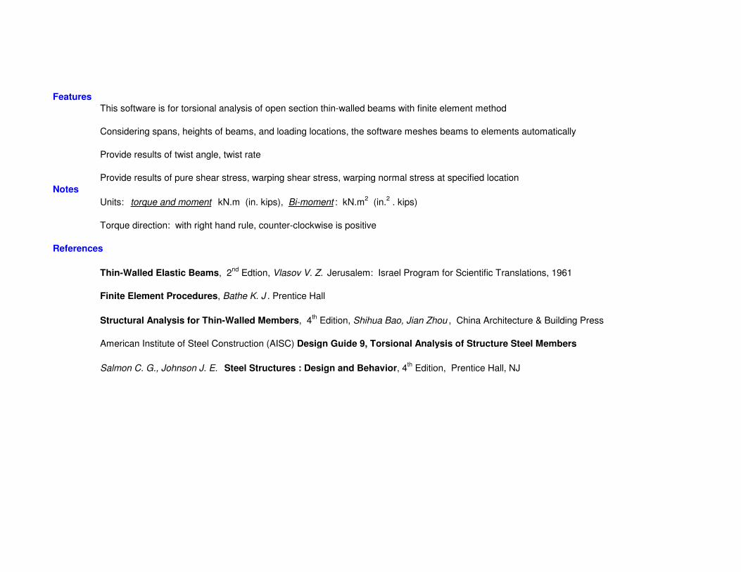
Features
This software is for torsional analysis of open section thin-walled beams with finite element method
Considering spans, heights of beams, and loading locations, the software meshes beams to elements automatically
Provide results of twist angle, twist rate
Provide results of pure shear stress, warping shear stress, warping normal stress at specified location
Notes
Units: torque and moment kN.m (in. kips), Bi-moment : kN.m2 (in.
2 . kips)
Torque direction: with right hand rule, counter-clockwise is positive
References
Thin-Walled Elastic Beams, 2nd
Edtion, Vlasov V. Z. Jerusalem: Israel Program for Scientific Translations, 1961
Finite Element Procedures, Bathe K. J . Prentice Hall
Structural Analysis for Thin-Walled Members, 4th Edition, Shihua Bao, Jian Zhou , China Architecture & Building Press
American Institute of Steel Construction (AISC) Design Guide 9, Torsional Analysis of Structure Steel Members
Salmon C. G., Johnson J. E. Steel Structures : Design and Behavior, 4th Edition, Prentice Hall, NJ

Instruction
1. General
E0 - Modulus of elasticity
u - Poisson ratio
X - Location from left support
After clicking button Apply, change X, then, click the screen, you can get the updated results
There are three shapes available (W, C, Z)
For left or right supports, "free", "pin", and "fix" can be selected
For torsional pin support: no rotation,torsion fixed, warping free
For torsional fix support: no rotation,torsion fixed, warping fixed
All inputs can be transferred to other unit automatically
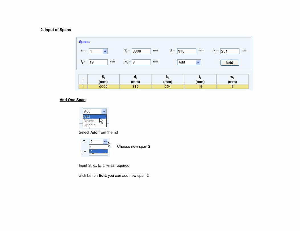
2. Input of Spans
Add One Span
Select Add from the list
Choose new span 2
Input Si, di, bi, ti, wi as required
click button Edit, you can add new span 2

Delete One Span
Select Delete from the list
Select Span 2
Click button Edit, you can delete span 2,
You couldn't delete span 1, but you can update input for span 1
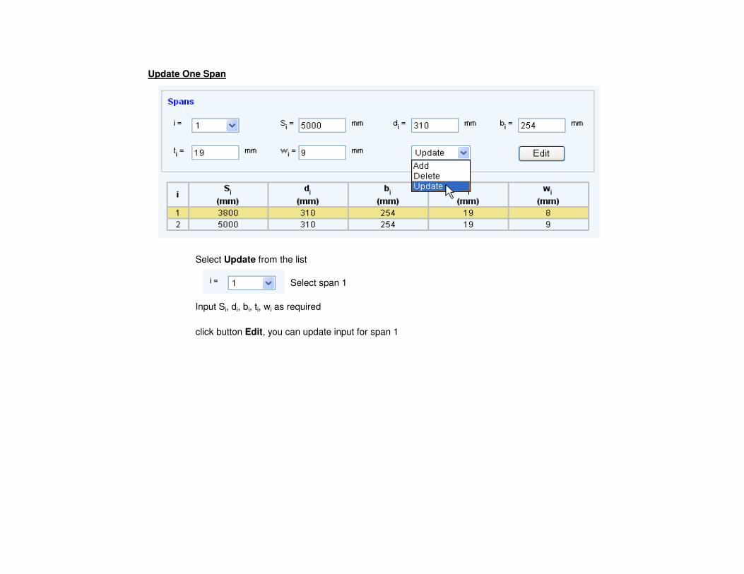
Update One Span
Select Update from the list
Select span 1
Input Si, di, bi, ti, wi as required
click button Edit, you can update input for span 1

3. Input of Loading
Add One Load
Select Add from the list
Choose loading number as 3
set loading on span 2
Select loading as Uniform
Input Tq, xb, xd as required
Click button Edit, you can add one load

Delete One Load
Select Delete from the list
choose loading number of 2
click button Edit, you can delete loading number of 2
You couldn't delete loading number of 1, but you can update input for loading number of 1

Update One Load
Select Update from the list
Choose loading number of 1
You can change information for # of span, Loading Type, Tq, xb, xd as required
Click button Edit, you can update input for the selected load

4. Review Results
Click botton Apply
Result for Twist Angle (θθθθ)
Select Twist Angle from the list
you can get envelope for rotation as following
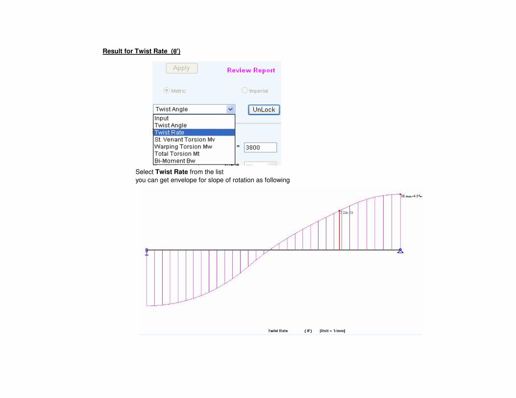
Result for Twist Rate (θθθθ')
Select Twist Rate from the list
you can get envelope for slope of rotation as following

Result for St. Venant Torsion Mv
Select St. Venant Torsion Mv from the list
you can get envelope for St. Venant torsion and diagram for pure shear stress at location X
Click Reivew Report, you can see the detail report for maximum pure shear stress at X
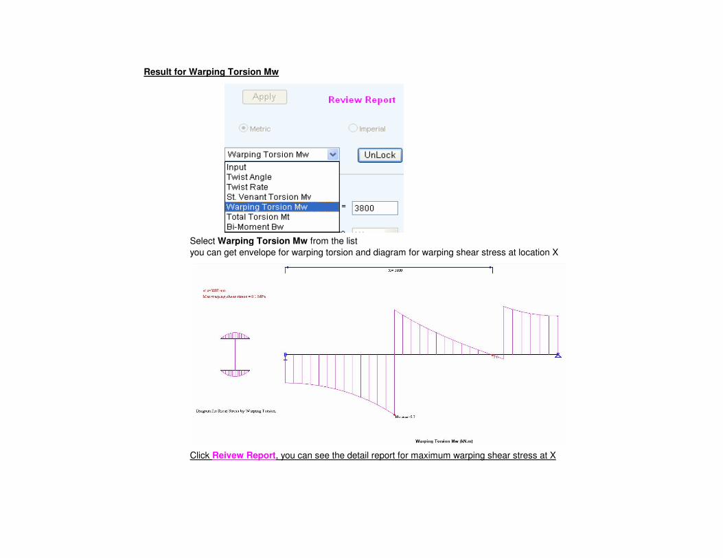
Result for Warping Torsion Mw
Select Warping Torsion Mw from the list
you can get envelope for warping torsion and diagram for warping shear stress at location X
Click Reivew Report, you can see the detail report for maximum warping shear stress at X

Result for Total Torsion Mt
Select Total Torsion Mt from the list
you can get envelope for total torsion
This torsion will apply for beam end connection design

Result for Bi-Moment Bw
Select Bi-Moment Bw from the list
you can get envelope for bi-moment and diagram for warping normal stress at location X
Click Reivew Report, you can see the detail report for maximum warping normal stress at X
click button UnLock, results are discarded, go back to input page

Theory for Torsional Analysis of Open Section Thin-Walled Members
Element Torsional Stiffness Matrix
Mti 2 iω γ /L2
2 iω (α + β)/L -2 iω γ /L2
2 iω (α + β)/L θi
Bωi 2 iω (α + β)/L 2 iω α -2 iω (α + β)/L 2 iω β θ'i
.=
Mtj -2 iω γ /L2
-2 iω (α + β)/L 2 iω γ /L2
-2 iω (α + β)/L θj
Bωj 2 iω (α + β)/L 2 iω β -2 iω (α + β)/L 2 iω α θ'j
Mti, Mtj = Total torsion at points i and j Mt = Mv + Mω
Mv = St. Venant (pure) torsion
Mω = Warping torsion
Bωi, Bωj = Bi-moment at points i and j
θi, θj = Twist angle at points i and j
θ'i, θ
'j = Twist rate (or first derivative of twist angle) at points i and j
iω = E0 . Jω / L
α = κ. ( κ - thκ) / {2 thκ . [κ - 2 th(κ/2)] }
β = κ (shκ - κ) / {2 shκ . [κ - 2 th(κ/2)] }
α + β = κ2 .th(κ/2) / {2 [κ - 2 th(κ/2)] }
γ = κ3 / { 2 [κ - 2 th(κ/2)] }
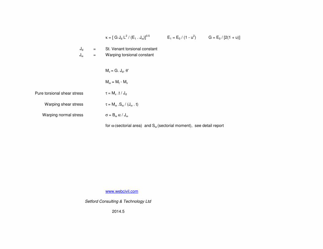
κ = [ G Jd L2 / (E1 . Jω)]
0.5E1 = E0 / (1 - u
2) G = E0 / [2(1 + u)]
Jd = St. Venant torsional constant
Jω = Warping torsional constant
Mv = G. Jd. θ'
Mω = Mt - Mv
Pure torsional shear stress τ = Mv .t / Jd
Warping shear stress τ = Mω .Sω / (Jω . t)
Warping normal stress σ = Bω ω / Jω
for ω (sectorial area) and Sω (sectorial moment), see detail report
www.webcivil.com
Setford Consulting & Technology Ltd
2014.5


![[AISC] Detailing for Steel Construction (Bookos.org)](https://img.pdfslide.us/doc/110x75/55cf91a0550346f57b8f0f85/aisc-detailing-for-steel-construction-bookosorg.jpg)