Embed Size (px)
Citation preview

MMaaddee ttoo WWoorrkk.. BBuuiilltt ttoo LLaasstt.. SSMM
P.O. Box 2000 State Road 15 NorthMilford, IN. 46542-2000 U.S.A.
219-658-4101 Fax 877-730-8825www.ctbinc.com
Made in the U.S.A.
A s s e m b l y I n s t r u c t i o n s
16000044
Page 2
WARNING: Improper installation, adjustment, alteration, service or maintenance can cause property damage, injury ordeath. Read the installation, operating and maintenance instructions thoroughly before installing or servicing this equipment.
L'installation déplacée, l'ajustement, le changement, le service ou l'entretien peuvent causer les dommages de propriété, lablessure ou la mort. Lire l'installation, fonctionnant et les instructions d'entretien à fond avant d'installer ou entretenir cetéquipement.
La instalación impropia, ajuste, modificación, servicio o mantenimiento puede causar dañado propiedad, herida o muerte.Lea la instalación, trabajar y mantenimiento instrucciones completamente antes de instalar o poner en funcionamientoequipo.
DANGERTake necessary precautions when working with sheet metal, edges may be SHARP!
Faites attention quand travaillant avec feuillet, les bords peuvent être AIGUISÉ !
¡Tome las precauciones necesarias al trabajar con metal laminado, las orillas pueden ser AGUDAS!
Read assembly guide completely before beginning setup. For most efficient assembly, two peopleshould work together on nests.
Lire assemblée guide avant que commencer. Deux gens devoir travailler ensemble sur les nids.
Lea la asamblea guía completamente antes de empezar montaje. Para la más asambleas eficientes,dos personas deben trabajar juntos en nidos.
ASSEMBLY INSTRUCTIONS FOR 8’ SIDE BELT NEST (16 & 20 Hole)
This guide will address the assembly of and parts identification for the revised side belt nest of commonpartition design. This guide will also include attachment of and parts identification for the passageways.
Installation of the collection table, variable speed control and egg belt as well as system operation willbe covered in a separate document.

Page 316000042
NNOOTTEESS
Page 4

Page 5
AN
est W
inch
Brk
t. 16
5000
002
BSt
ar K
ep N
ut 1
0-24
1800
0021
16C
Top:
9.6
” Hol
e S
BN
1650
0010
2D
Nes
t Lid
: SB
N16
5000
162
EH
H S
crew
10-
24X
2-1/
416
-900
788
FP
erch
: 95”
Dril
led
16-3
4533
2G
Egg
Tra
y C
over
1650
0017
2H
Egg
Tra
y A
ssm
: 9.6
” Hol
e16
5000
212
IC
ente
r Tra
y B
race
16-3
4053
6J
Per
ch/R
od S
uppo
rt B
rkt.
1650
0006
16K
Riv
et: P
op 3
/16”
16-3
3139
170
LSt
ringe
r:9
.6” H
ole
1650
0012
2M
Bot
tom
Sup
port
Wire
1600
0017
4N
SS
Hin
ge C
lam
p 3/
8”16
-890
412
OB
ack:
9.6
” Hol
e - S
hena
ndoa
h 16
5000
311
Bac
k: 9
.6” H
ole
- Cho
re-T
ime
1650
0033
1P
Uni
vers
al P
artit
ion
1650
0003
22Q
HH
Scr
ew 1
0-24
X1/
216
-900
778
RFl
ippe
r16
-301
901
SFl
ippe
r Mou
nt16
-347
901
TC
otte
r Pin
JD
3795
3
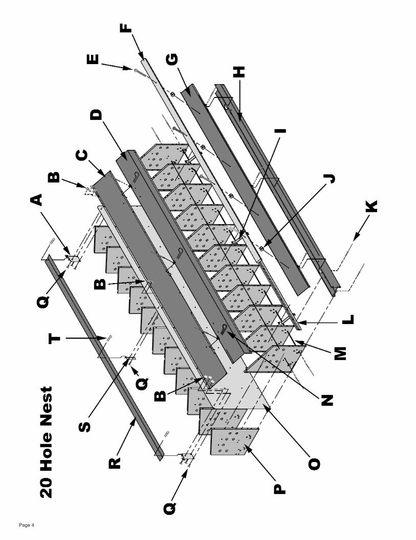
20 -H
OLE
NE
ST
Des
igna
tion
Par
t Des
crip
tion
Par
t Num
ber
Num
ber O
f Pie
ces
Per
8’N
est B
ody
Page 6

Page 7
AB
ack:
12”
Hol
e - S
hena
ndoa
h16
5000
301
Bac
k: 1
2” H
ole
- Cho
re-T
ime
1650
0032
1B
Top:
12”
Hol
e16
5000
092
CN
est L
id: S
BN
1650
0016
2D
Strin
ger:
12” H
ole
1650
0011
2E
HH
Scr
ew 1
0-24
X2-
1/4
16-9
0078
8F
Per
ch: 9
5” -
Dril
led
16-3
4533
2G
Egg
Tra
y C
over
1650
0017
2H
Egg
Tra
y A
ssem
bly
1650
0022
2I
Brk
t: P
erch
/ R
od S
pprt.
1650
0006
16J
Riv
et: P
op 3
/16”
16-3
3139
150
KC
ente
r Tra
y B
race
16-3
4053
6L
Bot
tom
Sup
port
Wire
1600
0017
4M
Hin
ge C
lam
p S
S 3
/8"
16-8
904
12N
Nut
10-
24 S
tar K
ep18
0000
2116
OU
nive
rsal
Par
titio
ns16
5000
0318
PN
est W
inch
Bra
cket
1650
0000
2Q
HH
Scr
ew 1
0-24
X1/
216
-900
778
RFl
ippe
r16
-301
901
SU
nive
rsal
Flip
per M
ount
16-3
4790
1T
Cot
ter P
inJD
3795
3
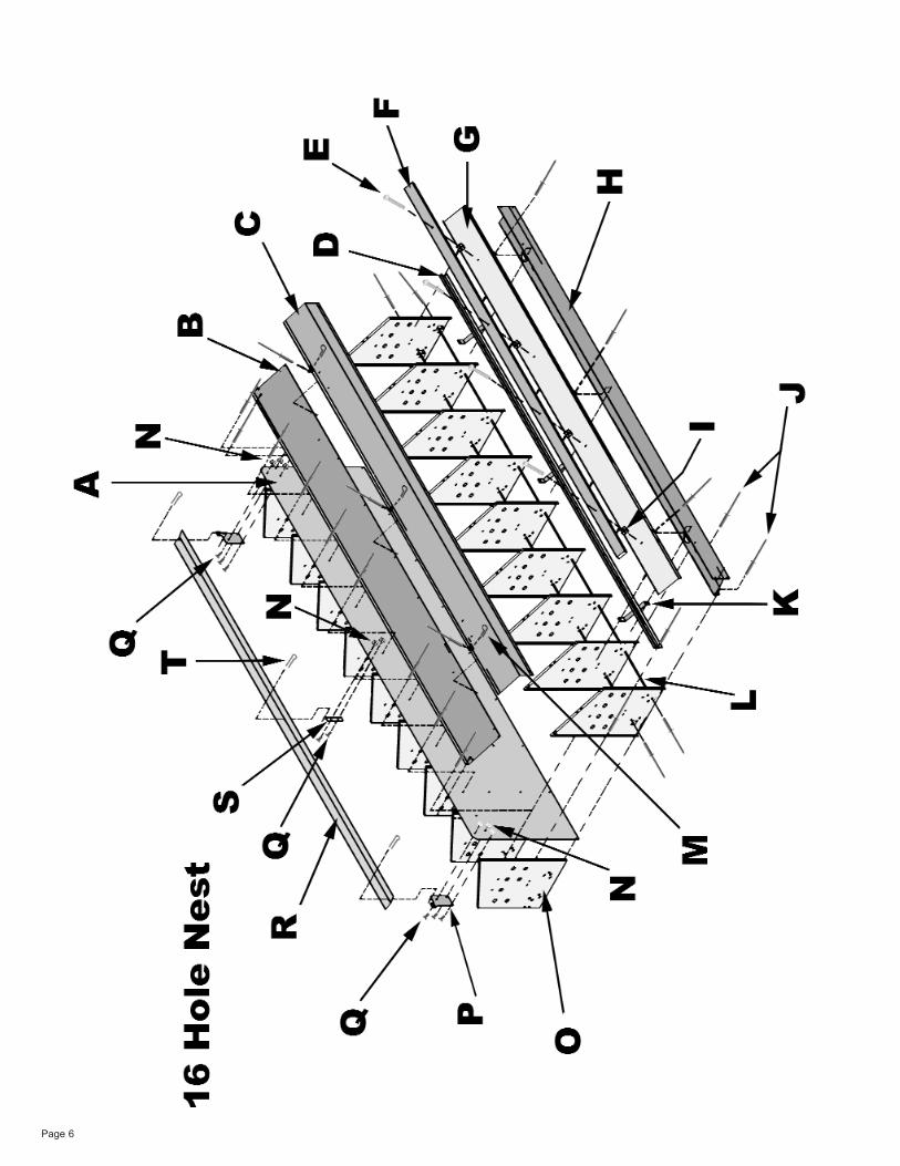
16 -H
OLE
NE
ST
Des
igna
tion
Par
t Des
crip
tion
Par
t Num
ber
Num
ber O
f Pie
ces
Per
8’N
est B
ody
Page 8
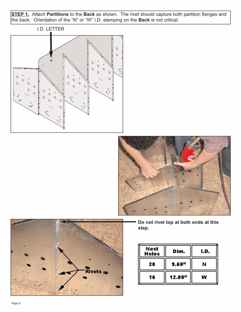
STEP 1. Attach Partitions to the Back as shown. The rivet should capture both partition flanges andthe back. Orientation of the “N” or “W” I.D. stamping on the Back is not critical.
I.D. LETTER
Do not rivet top at both ends at thisstep.
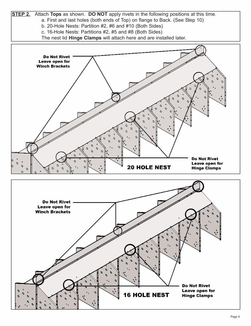
STEP 2. Attach Tops as shown. DO NOT apply rivets in the following positions at this time.a. First and last holes (both ends of Top) on flange to Back. (See Step 10)b. 20-Hole Nests: Partition #2, #6 and #10 (Both Sides)c. 16-Hole Nests: Partitions #2, #5 and #8 (Both Sides)The nest lid Hinge Clamps will attach here and are installed later.
Page 9
Page 10
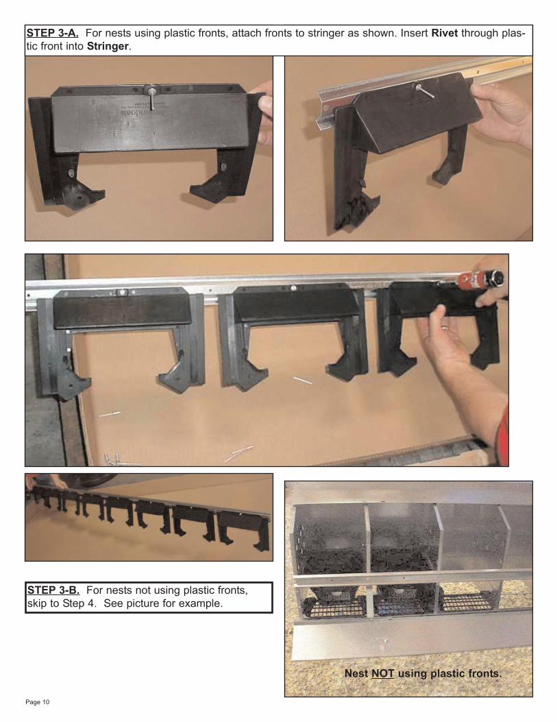
STEP 3-A. For nests using plastic fronts, attach fronts to stringer as shown. Insert Rivet through plas-tic front into Stringer.
STEP 3-B. For nests not using plastic fronts,skip to Step 4. See picture for example.
Nest NOT using plastic fronts.
Page 11
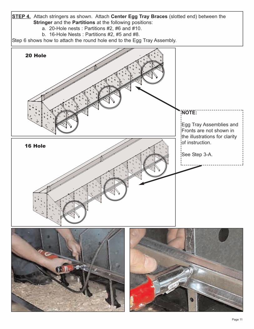
STEP 4. Attach stringers as shown. Attach Center Egg Tray Braces (slotted end) between the Stringer and the Partitions at the following positions:
a. 20-Hole nests : Partitions #2, #6 and #10.b. 16-Hole Nests : Partitions #2, #5 and #8.
Step 6 shows how to attach the round hole end to the Egg Tray Assembly.
20 Hole
16 Hole
NOTE:
Egg Tray Assemblies and Fronts are not shown inthe illustrations for clarityof instruction.
See Step 3-A.
Page 12
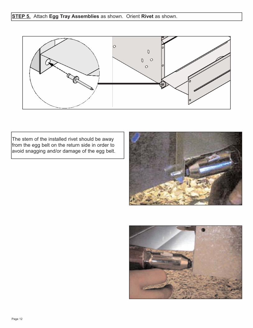
STEP 5. Attach Egg Tray Assemblies as shown. Orient Rivet as shown.
The stem of the installed rivet should be awayfrom the egg belt on the return side in order toavoid snagging and/or damage of the egg belt.
Page 13
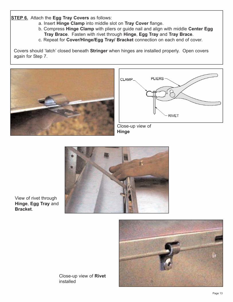
STEP 6. Attach the Egg Tray Covers as follows:a. Insert Hinge Clamp into middle slot on Tray Cover flange.b. Compress Hinge Clamp with pliers or guide nail and align with middle Center Egg
Tray Brace. Fasten with rivet through Hinge, Egg Tray and Tray Brace. c. Repeat for Cover/Hinge/Egg Tray/ Bracket connection on each end of cover.
Covers should ‘latch’ closed beneath Stringer when hinges are installed properly. Open covers again for Step 7.
View of rivet throughHinge, Egg Tray andBracket.
Close-up view ofHinge
Close-up view of Rivetinstalled
Page 14
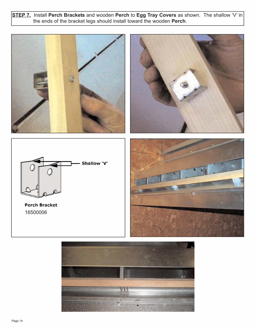
STEP 7. Install Perch Brackets and wooden Perch to Egg Tray Covers as shown. The shallow ‘V’ inthe ends of the bracket legs should install toward the wooden Perch.
16500006
Page 15
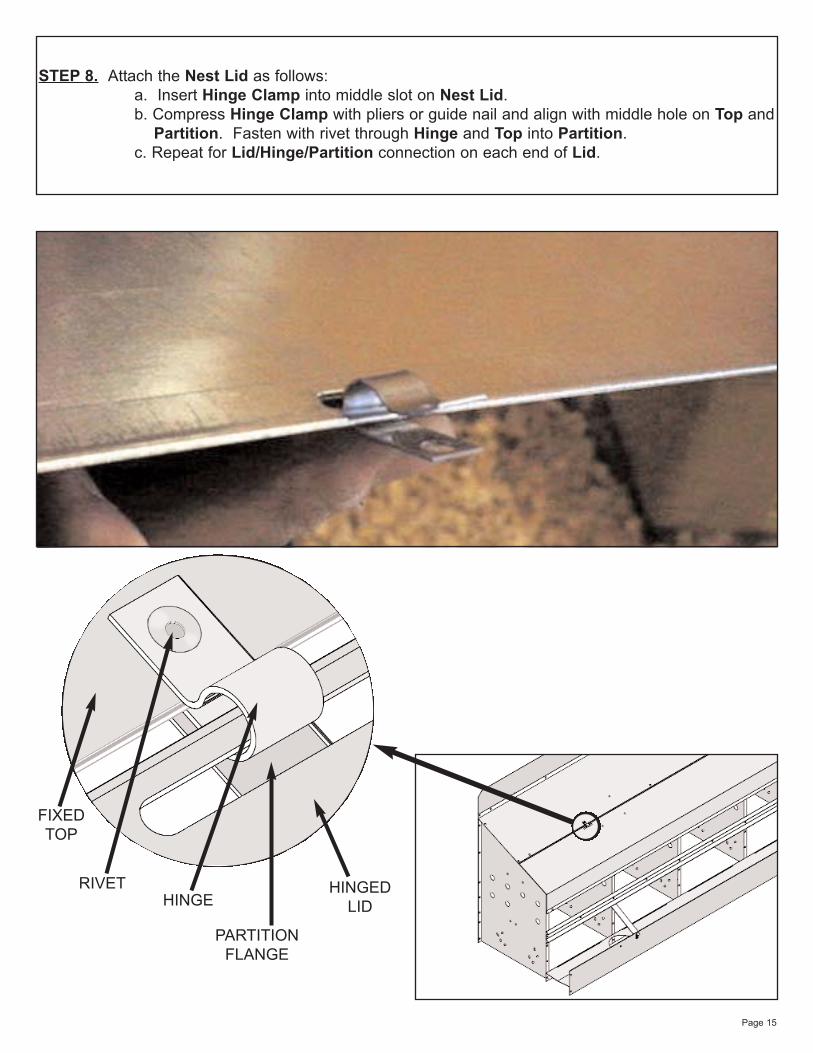
STEP 8. Attach the Nest Lid as follows: a. Insert Hinge Clamp into middle slot on Nest Lid.b. Compress Hinge Clamp with pliers or guide nail and align with middle hole on Top and
Partition. Fasten with rivet through Hinge and Top into Partition.c. Repeat for Lid/Hinge/Partition connection on each end of Lid.
FIXEDTOP
RIVETHINGE
PARTITIONFLANGE
HINGEDLID
Page 16
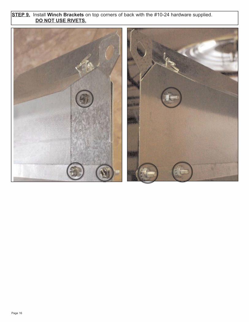
STEP 9. Install Winch Brackets on top corners of back with the #10-24 hardware supplied. DO NOT USE RIVETS.
Page 17
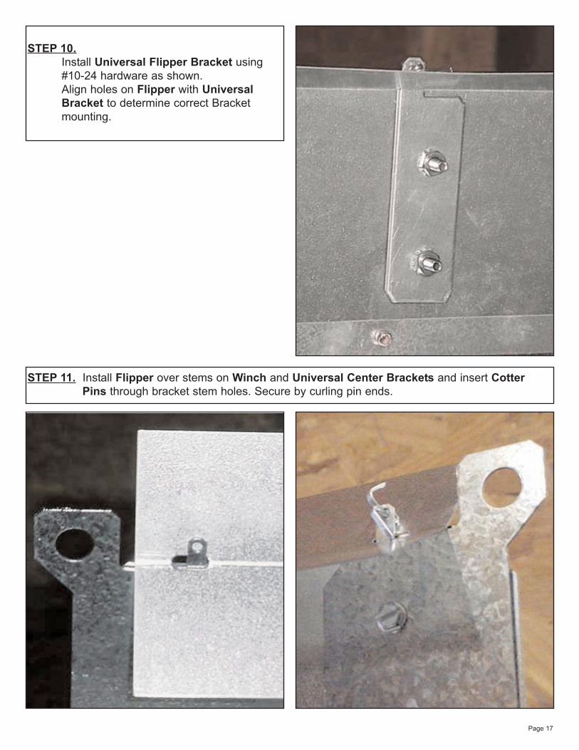
STEP 11. Install Flipper over stems on Winch and Universal Center Brackets and insert Cotter Pins through bracket stem holes. Secure by curling pin ends.
STEP 10.Install Universal Flipper Bracket using #10-24 hardware as shown. Align holes on Flipper with Universal Bracket to determine correct Bracket mounting.
Page 18
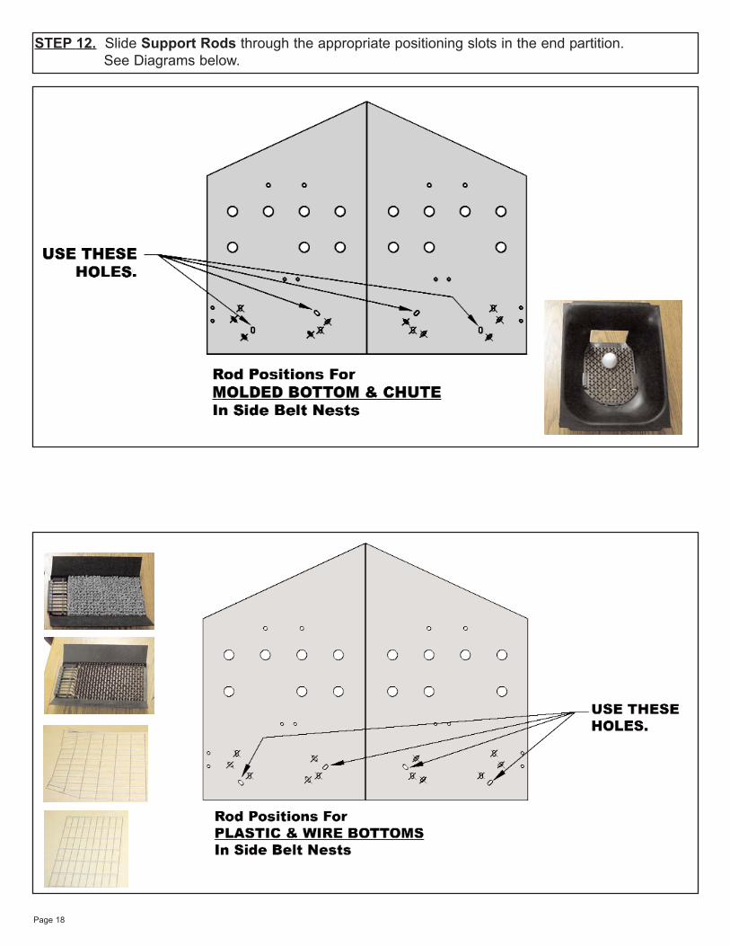
STEP 12. Slide Support Rods through the appropriate positioning slots in the end partition. See Diagrams below.
Page 19
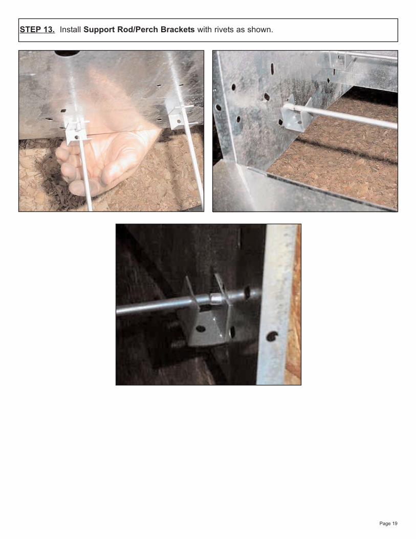
STEP 13. Install Support Rod/Perch Brackets with rivets as shown.
Page 20
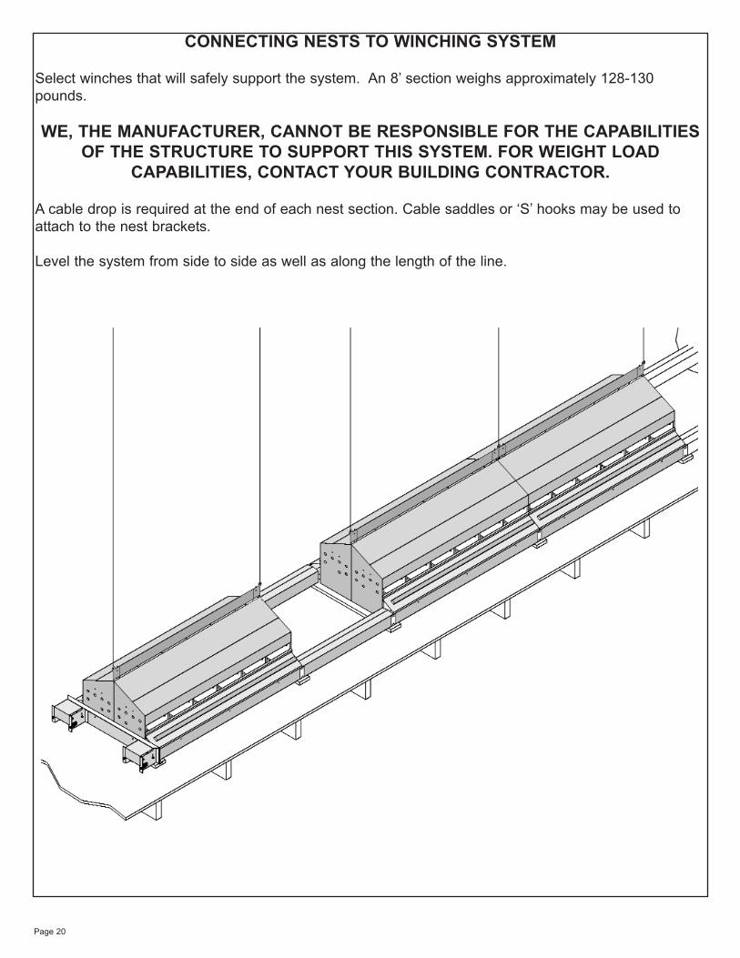
CONNECTING NESTS TO WINCHING SYSTEM
Select winches that will safely support the system. An 8’ section weighs approximately 128-130pounds.
WE, THE MANUFACTURER, CANNOT BE RESPONSIBLE FOR THE CAPABILITIESOF THE STRUCTURE TO SUPPORT THIS SYSTEM. FOR WEIGHT LOAD
CAPABILITIES, CONTACT YOUR BUILDING CONTRACTOR.
A cable drop is required at the end of each nest section. Cable saddles or ‘S’ hooks may be used toattach to the nest brackets.
Level the system from side to side as well as along the length of the line.
Page 21
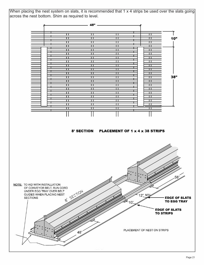
When placing the nest system on slats, it is recommended that 1 x 4 strips be used over the slats goingacross the nest bottom. Shim as required to level.
Page 22
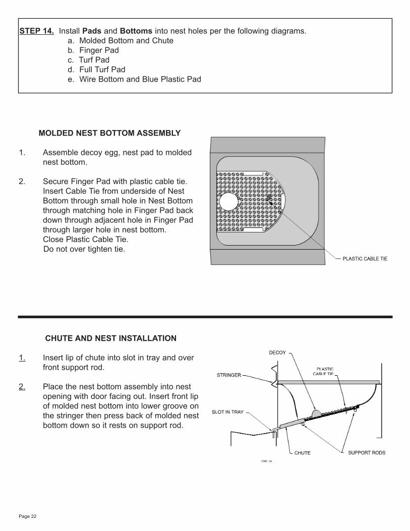
MOLDED NEST BOTTOM ASSEMBLY
1. Assemble decoy egg, nest pad to molded nest bottom.
2. Secure Finger Pad with plastic cable tie. Insert Cable Tie from underside of Nest Bottom through small hole in Nest Bottom through matching hole in Finger Pad back down through adjacent hole in Finger Pad through larger hole in nest bottom. Close Plastic Cable Tie. Do not over tighten tie.
CHUTE AND NEST INSTALLATION
1. Insert lip of chute into slot in tray and over front support rod.
2. Place the nest bottom assembly into nest opening with door facing out. Insert front lipof molded nest bottom into lower groove onthe stringer then press back of molded nestbottom down so it rests on support rod.
STEP 14. Install Pads and Bottoms into nest holes per the following diagrams.a. Molded Bottom and Chuteb. Finger Padc. Turf Padd. Full Turf Pade. Wire Bottom and Blue Plastic Pad
Page 23
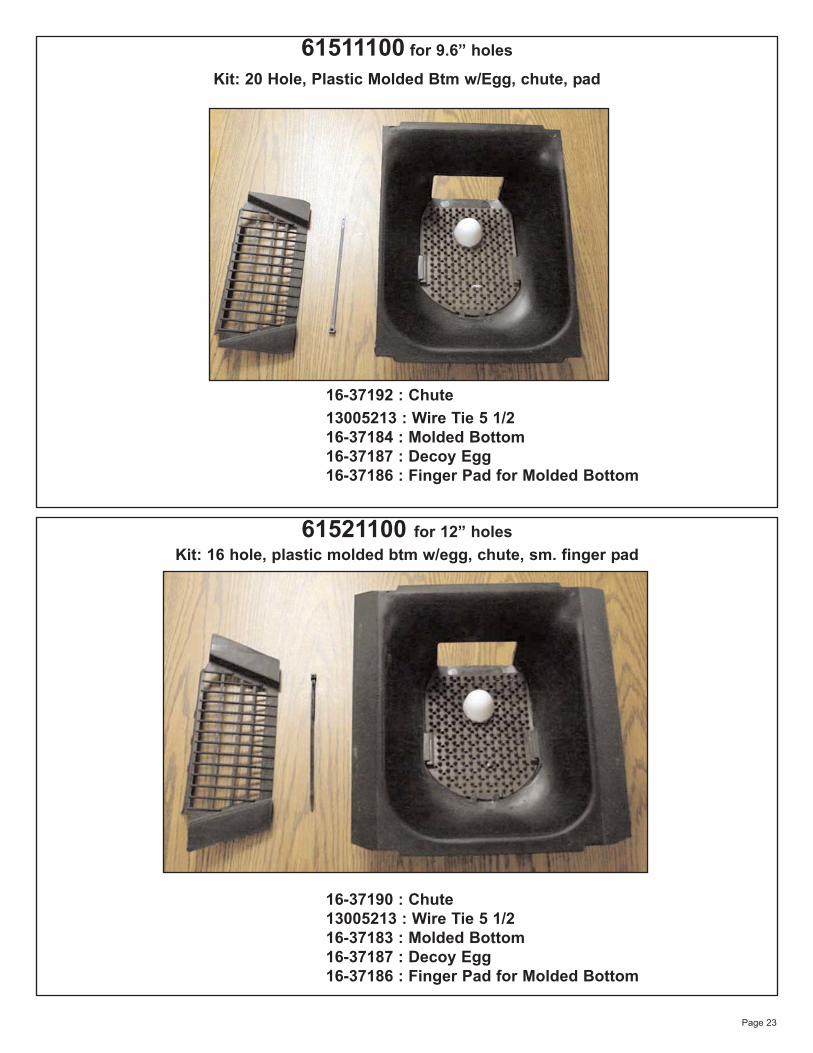
61511100 for 9.6” holes
Kit: 20 Hole, Plastic Molded Btm w/Egg, chute, pad
16-37192 : Chute13005213 : Wire Tie 5 1/216-37184 : Molded Bottom16-37187 : Decoy Egg16-37186 : Finger Pad for Molded Bottom
61521100 for 12” holesKit: 16 hole, plastic molded btm w/egg, chute, sm. finger pad
16-37190 : Chute13005213 : Wire Tie 5 1/216-37183 : Molded Bottom16-37187 : Decoy Egg16-37186 : Finger Pad for Molded Bottom
Page 24
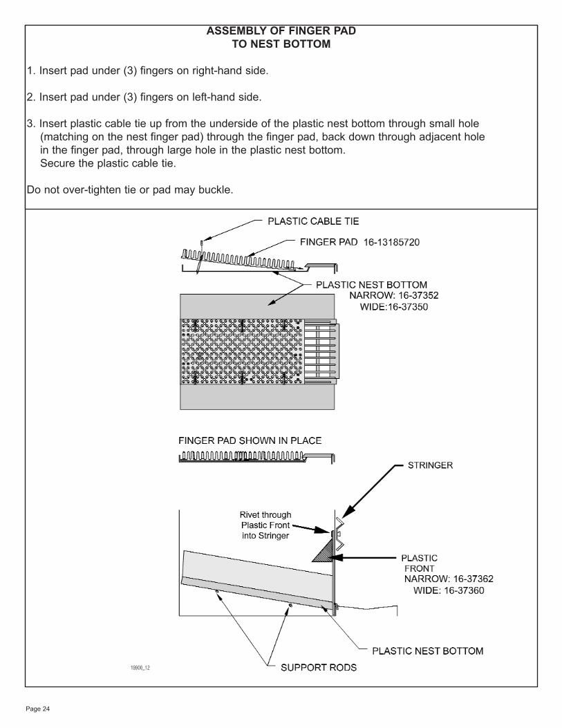
ASSEMBLY OF FINGER PAD TO NEST BOTTOM
1. Insert pad under (3) fingers on right-hand side.
2. Insert pad under (3) fingers on left-hand side.
3. Insert plastic cable tie up from the underside of the plastic nest bottom through small hole(matching on the nest finger pad) through the finger pad, back down through adjacent holein the finger pad, through large hole in the plastic nest bottom. Secure the plastic cable tie.
Do not over-tighten tie or pad may buckle.
Page 25
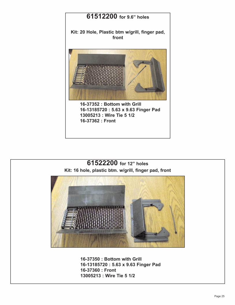
61512200 for 9.6” holes
Kit: 20 Hole, Plastic btm w/grill, finger pad,front
16-37352 : Bottom with Grill16-13185720 : 5.63 x 9.63 Finger Pad13005213 : Wire Tie 5 1/216-37362 : Front
61522200 for 12” holesKit: 16 hole, plastic btm. w/grill, finger pad, front
16-37350 : Bottom with Grill16-13185720 : 5.63 x 9.63 Finger Pad16-37360 : Front13005213 : Wire Tie 5 1/2
Page 26
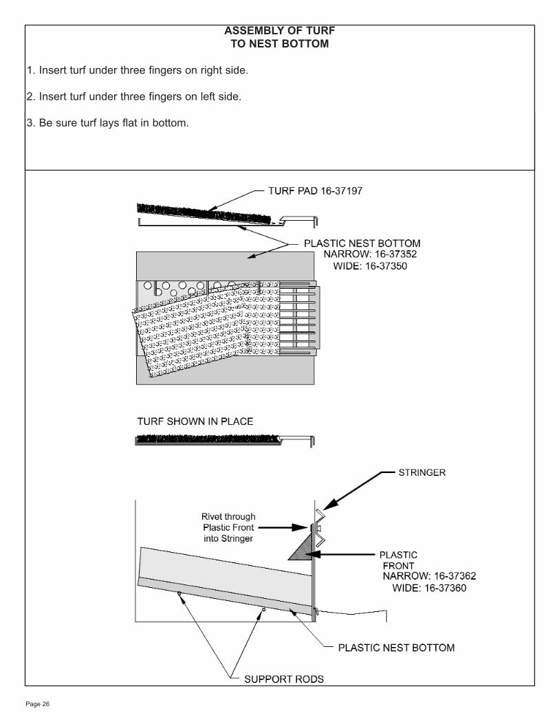
ASSEMBLY OF TURF TO NEST BOTTOM
1. Insert turf under three fingers on right side.
2. Insert turf under three fingers on left side.
3. Be sure turf lays flat in bottom.
Page 27
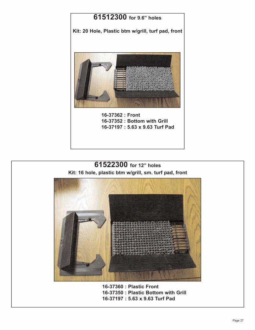
61522300 for 12” holesKit: 16 hole, plastic btm w/grill, sm. turf pad, front
16-37360 : Plastic Front16-37350 : Plastic Bottom with Grill16-37197 : 5.63 x 9.63 Turf Pad
61512300 for 9.6” holes
Kit: 20 Hole, Plastic btm w/grill, turf pad, front
16-37362 : Front16-37352 : Bottom with Grill16-37197 : 5.63 x 9.63 Turf Pad
Page 28
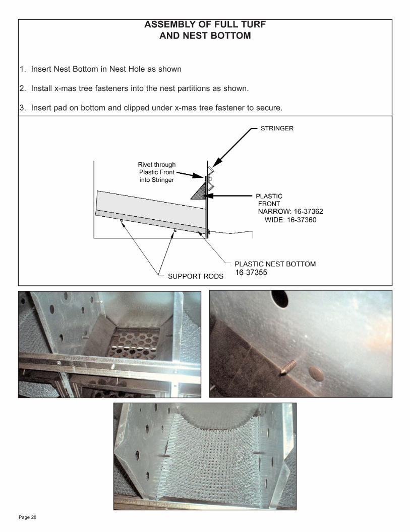
ASSEMBLY OF FULL TURF AND NEST BOTTOM
1. Insert Nest Bottom in Nest Hole as shown
2. Install x-mas tree fasteners into the nest partitions as shown.
3. Insert pad on bottom and clipped under x-mas tree fastener to secure.
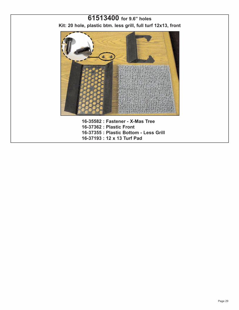
Page 29
61513400 for 9.6” holesKit: 20 hole, plastic btm. less grill, full turf 12x13, front
16-35582 : Fastener - X-Mas Tree16-37362 : Plastic Front16-37355 : Plastic Bottom - Less Grill16-37193 : 12 x 13 Turf Pad
Page 30
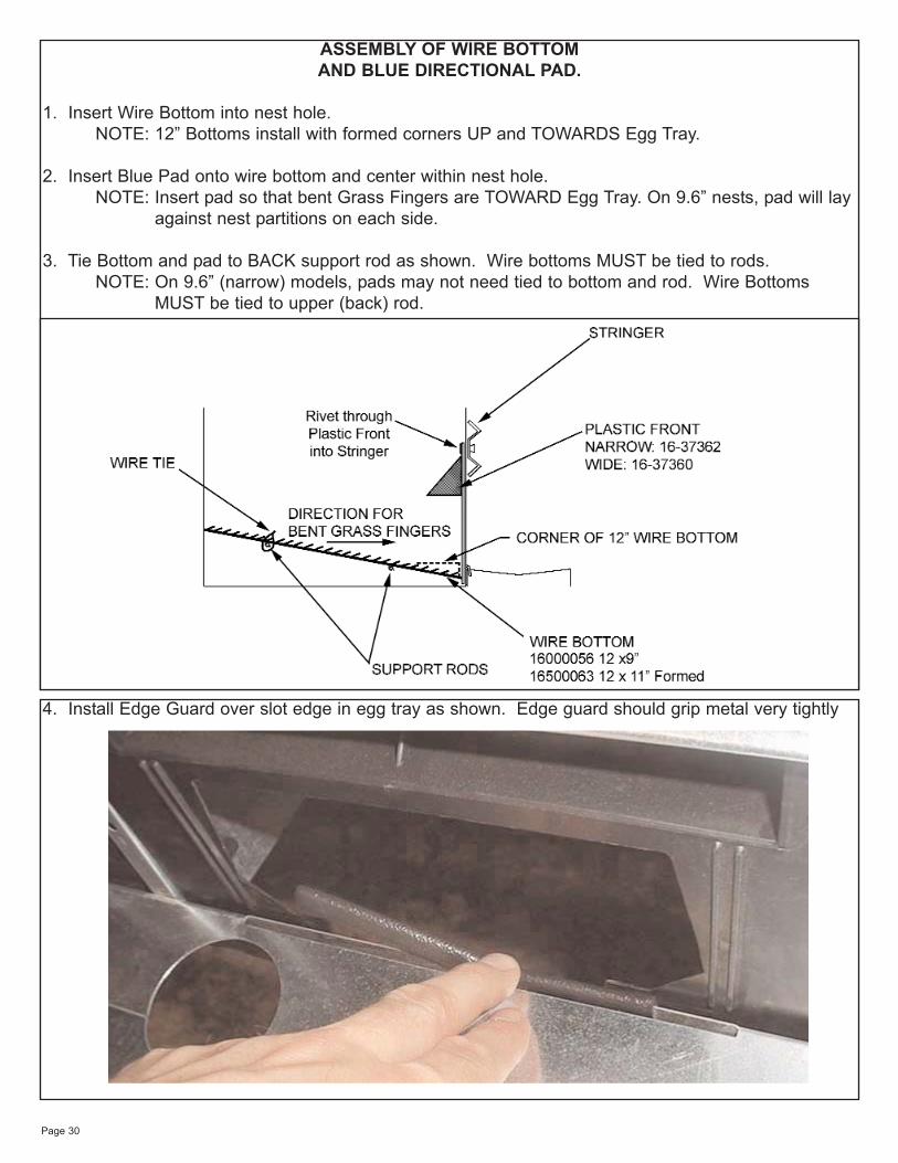
ASSEMBLY OF WIRE BOTTOMAND BLUE DIRECTIONAL PAD.
1. Insert Wire Bottom into nest hole.NOTE: 12” Bottoms install with formed corners UP and TOWARDS Egg Tray.
2. Insert Blue Pad onto wire bottom and center within nest hole.NOTE: Insert pad so that bent Grass Fingers are TOWARD Egg Tray. On 9.6” nests, pad will lay
against nest partitions on each side.
3. Tie Bottom and pad to BACK support rod as shown. Wire bottoms MUST be tied to rods.NOTE: On 9.6” (narrow) models, pads may not need tied to bottom and rod. Wire Bottoms
MUST be tied to upper (back) rod.
4. Install Edge Guard over slot edge in egg tray as shown. Edge guard should grip metal very tightly
Page 31
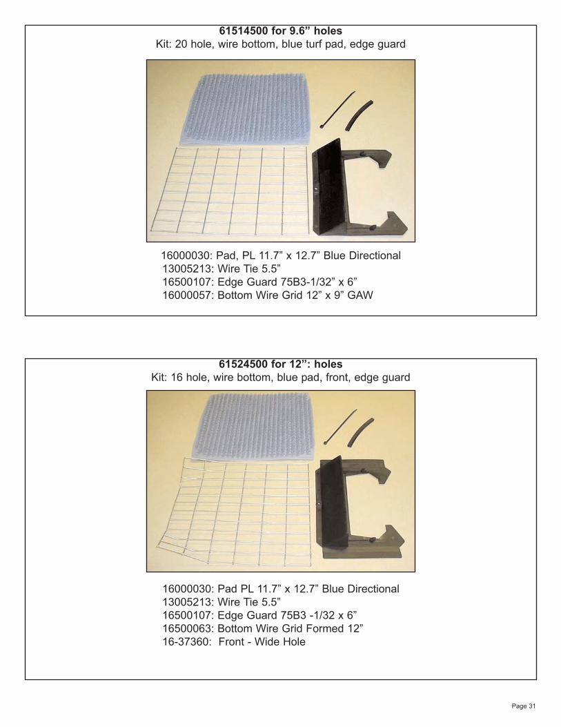
61524500 for 12”: holesKit: 16 hole, wire bottom, blue pad, front, edge guard
16000030: Pad PL 11.7” x 12.7” Blue Directional13005213: Wire Tie 5.5”16500107: Edge Guard 75B3 -1/32 x 6”16500063: Bottom Wire Grid Formed 12”16-37360: Front - Wide Hole
61514500 for 9.6” holesKit: 20 hole, wire bottom, blue turf pad, edge guard
16000030: Pad, PL 11.7” x 12.7” Blue Directional13005213: Wire Tie 5.5”16500107: Edge Guard 75B3-1/32” x 6”16000057: Bottom Wire Grid 12” x 9” GAW
Page 32
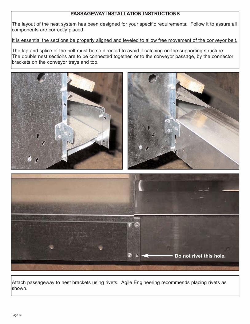
PASSAGEWAY INSTALLATION INSTRUCTIONS
The layout of the nest system has been designed for your specific requirements. Follow it to assure allcomponents are correctly placed.
It is essential the sections be properly aligned and leveled to allow free movement of the conveyor belt.
The lap and splice of the belt must be so directed to avoid it catching on the supporting structure. The double nest sections are to be connected together, or to the conveyor passage, by the connectorbrackets on the conveyor trays and top.
Attach passageway to nest brackets using rivets. Agile Engineering recommends placing rivets asshown.
Do not rivet this hole.
Page 33
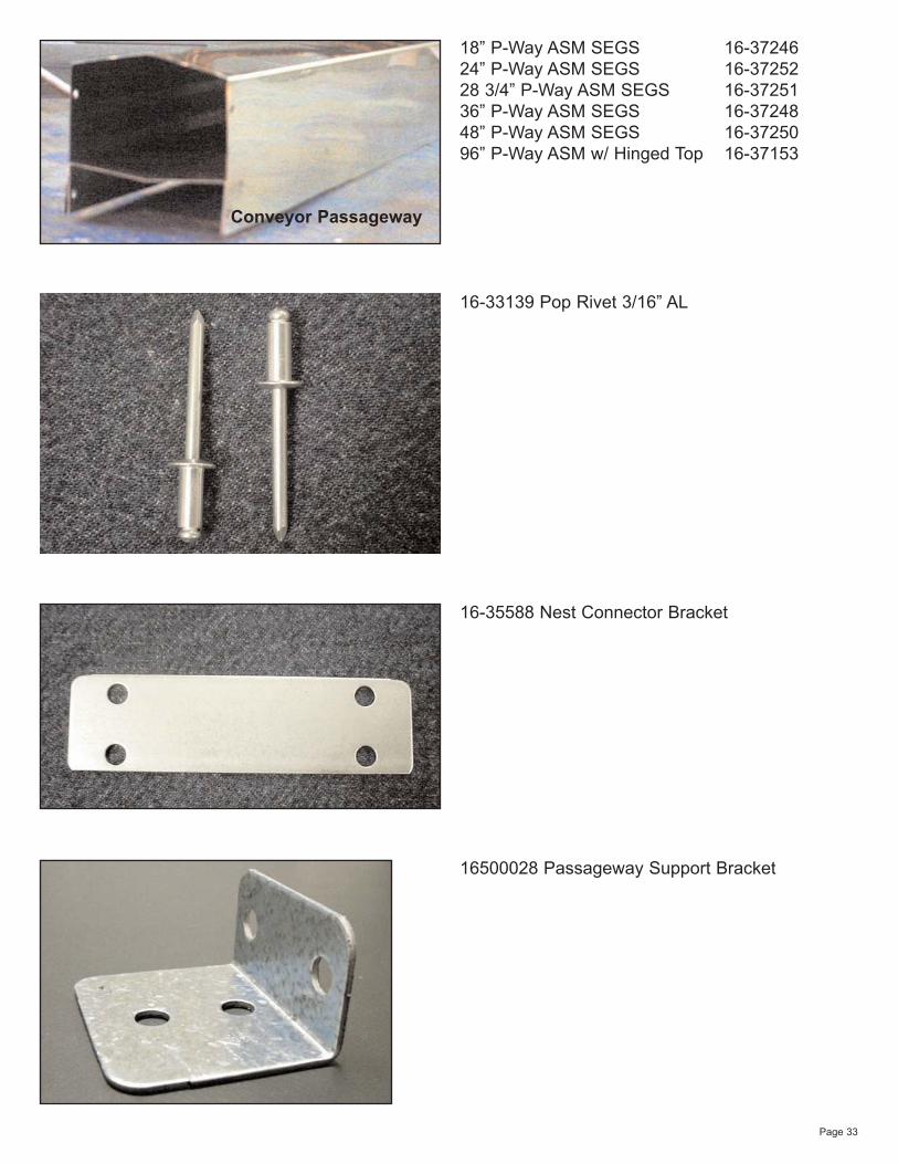
Conveyor Passageway
18” P-Way ASM SEGS 16-3724624” P-Way ASM SEGS 16-3725228 3/4” P-Way ASM SEGS 16-3725136” P-Way ASM SEGS 16-3724848” P-Way ASM SEGS 16-3725096” P-Way ASM w/ Hinged Top 16-37153
16-35588 Nest Connector Bracket
16500028 Passageway Support Bracket
16-33139 Pop Rivet 3/16” AL
Page 34
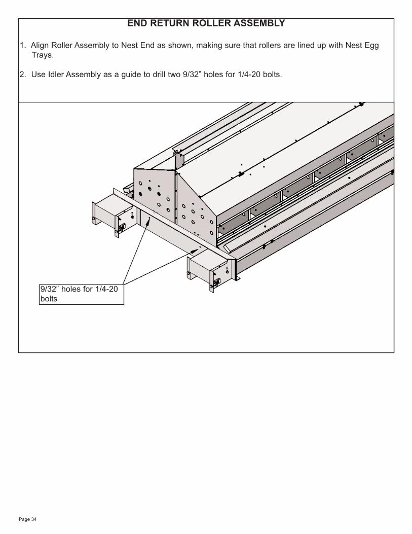
END RETURN ROLLER ASSEMBLY
1. Align Roller Assembly to Nest End as shown, making sure that rollers are lined up with Nest Egg Trays.
2. Use Idler Assembly as a guide to drill two 9/32” holes for 1/4-20 bolts.
9/32” holes for 1/4-20bolts
Page 35

Page 36
LIMITED WARRANTY:
CHORE-TIME INDUSTRIES, INC. WARRANTS THAT ITS PRODUCTS SHALL BE FREE FROM DEFECTSIN MATERIAL AND IN WORKMANSHIP FOR A PERIOD OF ONE (1) YEAR, WHEN PROPERLY USED FORTHEIR ORDINARY AND INTENDED PURPOSES AND WHEN PROPERLY MAINTAINED AND REPAIRED.
It is expressly agreed and understood that the Buyer's sole and exclusive remedy for any breach of thisLimited Warranty shall consist of the repair or replacement of any defective part or product when returned tothe Seller or to the Seller's authorized representative. It is further expressly agreed and understood that thissole and exclusive remedy shall be in lieu of and shall preclude any other liability of the Seller to the Buyer forany consequential or incidental damages sustained by the Buyer as a result of any defect in the productsincluding any loss of profits, loss of business opportunity, inconvenience, increased costs of operation, loss ofgoodwill, property damage or any other economic or business loss. The forgoing provisions of this LimitedWarranty constitute the final and complete expression of the agreement between the Buyer and Seller con-cerning express warranties of the product. Any other statements, representations, or promises made by sales-men, dealers, brokers, distributors or others which purport to expand or extend the coverage or term of thisLimited Warranty in any particular whatsoever, are unauthorized and shall not be binding on the Seller andshall not operate as warranties of the product. It is further understood that no salesman, dealer, distributor,broker or other person is authorized to change, modify, alter, amend, delete, or supplement the printed termsof this Limited Warranty in any manner or in any particular. No handwritten or typewritten interlineation, modifi-cation, amendment, addendum, deletion, supplement change or alteration of the printed terms of this LimitedWarranty shall be effective or shall be binding upon the Seller. All prior discussions, negotiations, statements,promises, agreements, understanding and representations concerning the character and quality of the prod-ucts are merged with and superseded by the terms of this Limited Warranty. The printed term of the LimitedWarranty contain the final and exclusive statement of the Buyer's and Seller's intentions, understanding andagreement concerning the subject matter hereof.
DISCLAIMER AND EXCLUSION OF WARRANTIES - The foregoing LIMITED WARRANTY is given in lieu ofand in substitution for any and all other warranties of any kind or description whatsoever, specifically includingthe implied warranty of the character or condition of the products. The SELLER disclaims and excludes anyimplied warranty or merchantability or fitness for a particular purpose in connection with the products subjectto this transaction. The SELLER further disclaims any express warranties concerning the products other thanthe foregoing "LIMITED WARRANTY". There are no warranties of any nature whatsoever which extendbeyond the express "LIMITED WARRANTY" set forth in the preceding paragraph.
Any exceptions to this warranty must be authorized in writing by an officer of the company. Chore-TimeIndustries reserves the right to change models and specifications at any time without notice or obligation toimprove previous models.