Embed Size (px)
Citation preview

B - 1
CT SIMULACT SIMULATTORS, CT PRODUCTS & LASERSORS, CT PRODUCTS & LASERS
Radiation Products Design, Inc. l Albertville, MN 55301 l (800) 497-2071 l Fax: (763) 497-2295 l www.rpdinc.com
B
CT / PET TABLE INSERT For Radiation Therapy Treatment Planning
Optional Magnification and Density RodsThe bottom of the CT/PET Table Insert has two 1/8" (3.31 mm)diameter aluminum rods, spaced 30 cm apart that run the length of theinsert and are used for magnification measurements.
A 1" (2.54 cm) diameter polystyrene rod and a 1" (2.54 cm) diameteracrylic rod are placed on either side of the center support. Both theserods run 72" (183 cm) along the bottom of the insert. These rodsprovide a reference for density checks.
SpecificationsTable Density: Polycarbonate - 1.2 g/cm3
Rod Density: Acrylic - 1.185 g/cm3 and Polystyrene - 1.05 g/cm3
Size: 84" L x 3/8" T (213.4 x 0.97 cm)Weight: 55 lb (25 kg)
The ideal CT Image for radiation therapy treatment planning shouldhave the patient on a flat table, magnification indicators, and densitymarkers.
The RPDinc CT/PET Table Insert is made of 3/8" (0.97 cm) clearpolycarbonate. The insert measures 84" (213.5 cm) long and thewidth is custom made to fit the CT or PET Table. A center support runsthe length of the insert to prevent any sag.
The CT/PET Table Insert is made with foam rubber edges and will siton top of the edges of the curved CT bed.
Item # Table Manufacturer Magnification and Density Rods683-310683-320683-330
GESiemensPhilips
IncludedIncludedIncluded
683-410683-420683-430
GESiemensPhilips
Not IncludedNot IncludedNot Included
GE LIGHTSPEED PHANTOM HOLDER FOR FLAT TABLE TOP 50 CM WIDE
The GE LightSpeed Phantom Holder attaches to a 50 cm wide flattop CT table. The GE LightSpeed Phantom Holder is an easy on,easy off unit for a flat top CT table. The bottom of the frontmounting plate references the holder to the front edge of the CTtable and the top is where the GE LightSpeed Phantom hooks onto the holder. A small thumb screw allows for leveling of thephantom. The two lock bars are spring loaded upward to be outof the way while securing to the CT table. The large adjustmentrange allows for different thicknesses of CT table tops. Thephantom holder has a built-in handle for easy carrying.
SpecificationsMaterial: Black Anodized AluminumOverall Size: 20.8" W x 4.5" L x 6.5" H (52.8 x 11.4 x 16.5 cm)Mounting Plate Size: 8.45" W x 4.67" H x 0.335" T(21.5 x 11.8 x 0.8 cm)
Item Description018-250 GE LightSpeed Phantom Holder f/FlatTable Top 50cm W

B - 2
CT SIMULACT SIMULATTORS, CT PRODUCTS & LASERSORS, CT PRODUCTS & LASERS
Radiation Products Design, Inc. l Albertville, MN 55301 l (800) 497-2071 l Fax: (763) 497-2295 l www.rpdinc.com
B
CT/MR SLESSINGER BOARD V2.0 FOR HDR BRACHYTHERAPY• CT and/or MR Compatible• Easy to Clean
The Slessinger Board is a padded sliding board that is CT and MRcompatible. It is designed to facilitate HDR brachytherapy,specifically for pelvic treatments. The patient can be transferredonto the board from the operating room couch and remain on theboard in recovery, during imaging for planning and until the HDRtreatment is given. The intent is to minimize patient movement toensure that the imaging for planning is not compromised by patientleg movement prior to treatment and thus delivering the treatmentplan faithfully. The legs are slightly elevated, affording readyaccess to the perineum and preventing applicators from restingagainst anything. Leg elevation is maintained with the use of two(2) tightening knobs at the end of the elevation panels. Transferson and off CT/MR/simulator couches are relatively easy due to thesmooth plastic bottom surface and side handles. The board is alsovery useful when a patient is transferred via ambulance from thesurgical facility to the treatment facility.
The CT/MR Slessinger Board V2.0 for HDR Brachytherapy hasthe additional benefit of having a hinged flexi-split to allow raisingthe head when on a stretcher. This version also includes heelcushions for additional patient comfort.
Image guided HDR brachytherapy is gaining in prominence.Prostate and gynecological applications are reliant on patientstability and comfort between the acquisition of imaging forplanning and treatment. Although the Slessinger Board wasdevised to facilitate precise prostate HDR brachytherapy itsapplication for image guided GYN HDR is also very significant withincreasing reliance on DVH analyses. The concept of limitingrotation of a multichannel APBI balloon is yet another possibleapplication, by avoiding the patient walking between imaging andtreatment prior to each treatment fraction. The rationale anddescription of the Slessinger Board has also been described in theBrachytherapy Journal article by Slessinger, entitled "Practicalconsiderations for prostate HDR brachytherapy", published earlyin 2010.
The Slessinger Board can be easily cleaned with non-causticgermicidal cloths or sprays. Patients may not be carried on theSlessinger Board, but rather are transferred directly from onesupport to another.
MR Safe
SpecificationsBase Dimensions: 21" W x 72" L x 0.75" T (53.3 x 183 x 1.9 cm)Base Material: Corrugated polypropylenePad Dimensions: 20.5" W x 69" L x 1.5" T (52.3 x 175 x 3.8 cm)Pad Material: Vinyl coated closed cell foamAssembled Board Weight: 26 lb (11.8 kg)Weight Limit: 350 lb (159 kg)
Item Description946-004 CT/MR Slessinger Board V2.0 for HDR Brachytherapy
B - 3
CT SIMULACT SIMULATTORS, CT PRODUCTS & LASERSORS, CT PRODUCTS & LASERS
Radiation Products Design, Inc. l Albertville, MN 55301 l (800) 497-2071 l Fax: (763) 497-2295 l www.rpdinc.com
B
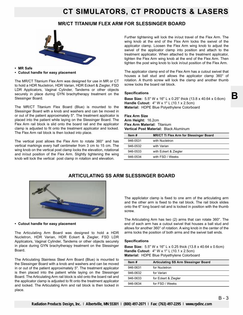
MR/CT TITANIUM FLEX ARM FOR SLESSINGER BOARD
• MR Safe• Cutout handle for easy placement
The MR/CT Titanium Flex Arm was designed for use in MR or CTto hold a HDR Nucletron, HDR Varian, HDR Eckert & Ziegler, FSDLDR Applicators, Vaginal Cylinder, Tandems or other objectssecurely in place during GYN brachytherapy treatment on theSlessinger Board.
The MR/CT Titanium Flex Board (Blue) is mounted to theSlessinger Board with a knob and washers and can be moved inor out of the patient approximately 5". The treatment applicator isplaced into the patient while laying on the Slessinger Board. TheFlex Arm rail block is slid onto the board rail and the applicatorclamp is adjusted to fit onto the treatment applicator and locked.The Flex Arm rail block is then locked into place.
The vertical post allows the Flex Arm to rotate 360° and hasvertical markings every half centimeter from 3 cm to 15 cm. Thewing knob on the vertical post clamp locks the elevation, rotationaland in/out position of the Flex Arm. Slightly tightening the wingknob will lock the vertical post clamp in rotation and elevation.
Further tightening will lock the in/out travel of the Flex Arm. Thewing knob at the end of the Flex Arm locks the swivel of theapplicator clamp. Loosen the Flex Arm wing knob to adjust theswivel of the applicator clamp into position and attach to thetreatment applicator. When attached to the treatment applicator,tighten the Flex Arm wing knob at the end of the Flex Arm. Thentighten the post wing knob to lock in/out position of the Flex Arm.
The applicator clamp end of the Flex Arm has a cutout swivel thathouses a ball stud and allows the applicator clamp 360° ofrotation. A thumb screw will lock the clamp and another thumbscrew locks the board rail block.
SpecificationsBase Size: 5.5" W x 16" L x 0.25" thick (13.8 x 40.64 x 0.6cm)Handle Cutout: 4" W x 1" L (10.1 x 2.5cm)Material: HDPE Blue Polyethylene Colorboard
Flex Arm SizeArm Height: 16.2cmFlex Arm Material: TitaniumVertical Post Material: Black Aluminum
ARTICULATING SS ARM SLESSINGER BOARD
The appliclator clamp is fixed to one arm of the articulating armand the other arm is fixed to the rail block. The rail block slidesonto the 6" long board rail and is locked in position with the thumbscrew.
The Articulating Arm has two (2) arms that can rotate 360°. Theend of each arm has a cutout swivel that houses a ball stud andallows for another 360° of rotation. A wing knob in the center of thearms locks the position of both arms and the swivel ball ends.
SpecificationsBase Size: 5.5" W x 16" L x 0.25 thick (13.8 x 40.64 x 0.6cm)Handle Cutout: 4" W x 1" L (10.1 x 2.5cm)Material: HDPE Blue Polyethylene Colorboard
Item #946-0531
946-0533
MR/CT Ti Flex Arm for Slessinger Boardwith Nucletron
with Eckert & Ziegler946-0532 with Varian
946-0534 with FSD / Weeks
Item #946-0631
946-0633
Articulating SS Arm Slessinger Boardfor Nucletron
for Eckert & Ziegler946-0632 for Varian
946-0634 for FSD / Weeks
• Cutout handle for easy placement
The Articulating Arm Board was designed to hold a HDRNucletron, HDR Varian, HDR Eckert & Ziegler, FSD LDRApplicators, Vaginal Cylinder, Tandems or other objects securelyin place during GYN brachytherapy treatment on the SlessingerBoard.
The Articulating Stainless Steel Arm Board (Blue) is mounted tothe Slessinger Board with a knob and washers and can be movedin or out of the patient approximately 5". The treatment applicatoris then placed into the patient while laying on the SlessingerBoard. The Articulating Arm rail block is slid onto the board rail andthe applicator clamp is adjusted to fit onto the treatment applicatorand locked. The Articulating Arm and rail block is then locked inplace.

B - 4
CT SIMULACT SIMULATTORS, CT PRODUCTS & LASERSORS, CT PRODUCTS & LASERS
Radiation Products Design, Inc. l Albertville, MN 55301 l (800) 497-2071 l Fax: (763) 497-2295 l www.rpdinc.com
B
VISIONMARK™ CT
The VisionMark™ CT markers offer the perfect combination oftack surfaces and easy-peel corners, keeping the markerscorrectly positioned with minimal discomfort to the patient onremoval. These NON-METALLIC markers reduce read time onCT scans with virtually no scatter. These sizes and ball densitiesare perfect for all CT skin marking applications. Available in 3 mm,4 mm, and 5 mm ball sizes. No lead means they are safer foryourself, your patient and the environment.
680-305680-310680-312680-314
2.0 mm Ball2.5 mm Ball3.0 mm Ball4.0 mm Ball
50Item Visionmark™ CT Quantity
505050
680-316 5.0 mm Ball 50
CT MarkWire and Dots
The CT Mark wire and dots are a new blue formation designedspecifically for CT. These markers are lead free, will not causeartifact (scatter) on CT scans and the labels are latex-free.
CT MARKER-INDICATOR RADIOPAQUE• Use in CT, RT Simulation, Treatment Planning, Diagnostic
Radiology, Angiofraphy, Mammography and Fluoroscopy• Use to identify masses, scar tissue, moles, birth marks or any point
of interest• Provides a clear and accurate reference point with no spray
artifacts• Flat marker - will not indent tissue• Disposable• Clear adhesive backing• Multiple sizes available• Lead Free• Crosses - 0.38" L (9.5 mm)• Dots - 0.125" diameter (3 mm)• Lines - cut to desired length• NOT for use in MRI
680-350680-352680-354
CT Mark Wire, 2.0 mmCT Mark, 2.3 mmCT Mark, 4.0 mm
300 cm
Item Description Quantity
11050
680-349 CT Mark Wire, 1.0 mm 330 cm
680-401 680-403 680-410
680-402680-404 680-411
680-405 680-412
680-406
680-408
Item # CT Marker-Indicator Radiopaque Quantity680-401 Crosses, 10 mm 130680-402 Crosses, 20 mm 130680-403 Dots, 1.5 mm 115680-404 Dots, 2.0 mm 115680-405 Dots, 2.5 mm 115
680-406 Dots, 3.0 mm 115680-408 Dots, 4.0 mm 115680-410 Line, 0.5 mm 69" (175 cm)680-411 Line, 1.0 mm 66" (167 cm)680-412 Line, 1.50 mm 62.5" (159 cm)
Item # CT Marker-Indicator Radiopaque Quantity

B - 5
CT SIMULACT SIMULATTORS, CT PRODUCTS & LASERSORS, CT PRODUCTS & LASERS
Radiation Products Design, Inc. l Albertville, MN 55301 l (800) 497-2071 l Fax: (763) 497-2295 l www.rpdinc.com
B
X-LINE™PRECISION RADIOTHERAPY TAPE FOR CT SIMULATION
A Solution to CT Simulation Image Distortionin Obese Patients
• More Accurate• Fast and Simple• Low-Cost• Optimal Dosage• Latex Free
X-Line™ allows accurate contouring within distorted regions of theCT image, improving radiotherapy outcomes.
Obese patients must be imaged with the extended field of view(eFOV), often resulting in distorted body contours. X-Line™provides a series of reliable dots within the distorted sections ofthe eFOV, allowing for easy identification of the true body contour.The radiopaque lines on X-Line™ show up as hyperdense in CTsimulation. Connect underneath the dots to get an accurate bodycontour - it’s that easy!
Body contour distortion from large patients in the eFOV• GE Discovery CT590 RT, Optima CT580 RT and LightSpeed RT
have a scan FOV (sFOV) of 50cm and a 65cm extended FOV(eFOV) option
• Siemens Somotom models have a 50cm sFOV and eFOV up to80cm
• Body regions within the eFOV is distorted and contains artifact,resulting in an inaccurate body contour
• Body contour inaccuracies can lead to incorrect SSD and dosage calculations
X-Line™ General Instructions• Apply X-Line™ to all body regions that might fall outside of the
scan field of view• Tear a strip length that fully encompasses the region of interest• Expect to use 3-5 strips per patient, depending on their sizeStep 1 - Peel• Peel away the protective backing• X-Line™ is kiss cut to make for easier removalStep 2 - Apply• Apply X-Line™ to the region of interest• Orient the radiopaque lines perpendicular to the direction of the
CT cross section• Space the X-line™ strips approximately 1 inch apart• Only apply each X-Line™ strip onceStep 3 - Scan• Then, perform the CT scan as usual• Remove and discard the X-Line™ strips after the scanStep 4 - Connect• Finally, connect just underneath the bright, hyperdense dots in
the resulting CT images• Connecting underneath the dots avoids including these
hyperdense regions in the radiation dose planning
SpecificationsSize: 2" wide (5.08 cm) with three equally spaced radiopaquelines 1" apart (2.54 cm)Quantity: Rolls are 50' long (15.24 m) with perforationsspaced every 2" (5.08 cm).
680-470680-475
X-Line Tape, Full AdhesiveX-Line Tape, Partial Adhesive
Item Description
Clear scanwithin sFOV
Distorted imagein 65cm eFOV
X-Line™connect-the-dots
body contour
Siemens HDFOV PRO Phantom

B - 6
CT SIMULACT SIMULATTORS, CT PRODUCTS & LASERSORS, CT PRODUCTS & LASERS
Radiation Products Design, Inc. l Albertville, MN 55301 l (800) 497-2071 l Fax: (763) 497-2295 l www.rpdinc.com
B
CT MARKERMaterial: Aluminum WireSize: 1" (2.54 cm) Square
Head
Foot
Cut CenterItem #680-125
DescriptionCT Marker
MULTIMODAL SPOT MARKERSWritten Verification of Radioactive Materials License is Required to Place an Order
10 μCi.37 MBq
25 μCi.925 MBq
50 μCi1.85 MBq
100 μCi3.7 MBq
MMS02MMS02MMS02MMS03MMS03
680-200680-210680-220680-230680-240
680-201680-211680-221680-231680-241
680-202680-212680-222680-232680-242
680-203680-213680-223680-233680-243
MMS03 680-250 680-251 680-252 680-253
Model
Co-57Ge-68Na-22Co-57Ge-68Na-22
Nuclide
The Multimodal Spot Markers are used for patient orientation andimage registration in camera studies. The Co-57 is used forCT-SPECT and Ge-68 and Na-22 for CT-PET fusion imaging.
SpecificationsModel MMS02Capsule: 1" dia. x 1/4" (2.54 x 0.64 cm) thick clear cast acrylicActive Dimensions: 1.5 x 1.5 mm cylinderCT Target: 1/4" (0.64 cm) OD bone-equivalent ring (surroundsactive element)Suggested Usage: Multimodal fiducial marker for imagecoregistration
Model MMS03Capsule: 1" dia. x 1/4" (2.54 x 0.64 cm) thick clear cast acrylic withetched “crosshairs” centered on active element for laser alignmentActive Dimensions: 1 mm diameter sphereCT Target: 2 mm OD bone-equivalent ring (surrounds activeelement)Suggested Usage: Multimodal fiducial marker for imagecoregistration
Item 462-030 Multi-Modality Markers for Nuc Med/PET• Visible on Nuclear Medicine, CT and MRI scans• Liquid-containing well suitable for injection of short-life
radionuclide using a conventional hypodermic needle• 15 mm outer diameter and 3.5 mm thick• 5 mm axial hole• Composed from hydrogel with medical grade adhesive
MULTI-MODALITY MARKERS
462-029 462-030
Item 462-029 Multi-Modality Markers for Radiology/RadiationTherapy• Appears as bright object on CT, MRI and Diagnostic Imaging
scans• Inner center hole affords passage of needle through central hole• 15 mm outer diameter and 3.5 mm thick• 5 mm axial hole with 2 mm central hole• Composed from hydrogel with medical grade adhesive
Item #462-029
DescriptionMulti-Modality Markers forRadiology/Radiation Therapy
Quantity50
462-030 Multi-Modality Markers for Nuc Med/PET 50

B - 7
CT SIMULACT SIMULATTORS, CT PRODUCTS & LASERSORS, CT PRODUCTS & LASERS
Radiation Products Design, Inc. l Albertville, MN 55301 l (800) 497-2071 l Fax: (763) 497-2295 l www.rpdinc.com
B
CT MARKING WIRE
682-080Item China Markers Length
682-090
682-100
Aluminum Wire0.080" (2.03 mm) Diameter
42'(12.8 m)165'(50.3 m)67'(20.4 m)
Aluminum Wire0.040" (1.02 mm) DiameterAluminum Wire0.064" (1.63 mm) Diameter
682-090 682-100
SHADOWFORM MARKERS• T-Bar handle which can be removed for insertion of barium• Disposable• Rectal markers are available in two lengths and are marked
at 1 cm intervals• No cross contamination• Outlines the soft tissue of the pelvic region• Latex-free• Markers are made from a soft, smooth, flexible plastic• Used for Simulation and CT Planning• Provides excellent localization of pelvic structures
460-501 460-502 460-503
18 cm Vaginal Marker 1038 cm Rectal Marker10 cm Rectal Marker
Item Shadowform Markers Quantity
1010
The NON-METALLIC CT Rectal Marker is a flexible tube packedwith teflon balls spaced at 1 cm intervals from center to center.
The Rectal Marker is used to accurately obtain both the rectumposition and magnification by counting the balls. This determinesthe rectum location relative to the radiation field.
An adjustable anus marker can be utilized during CT simulation.
The Rectal Marker can be used as a vaginal marker or an externalmarker.
SpecificationsSterilization: GasTubing: 5/16" (8 mm) Dia. x 30 cm FlexibleBalls: 3/16" (5 mm) Dia. Spaced Every cmAnus Locator: Adjustable DelrinLatex Cover: 2.0 cm Dia. x 30 cm L
CT RECTAL MARKERRectal - Vaginal - External
460-501 460-502 460-503
Item #460-010
DescriptionCT Rectal Marker with Anus Marker
460-006-12 Latex Cover for Rectal Marker, 12/pkg460-006-24 Latex Covers for Rectal Marker, 24/pkg

B - 8
CT SIMULACT SIMULATTORS, CT PRODUCTS & LASERSORS, CT PRODUCTS & LASERS
Radiation Products Design, Inc. l Albertville, MN 55301 l (800) 497-2071 l Fax: (763) 497-2295 l www.rpdinc.com
B
CT VAGINAL DEPTH SCALE
The NON-METALLIC CT Vaginal Depth Scale is 1.6 cm indiameter and 26 cm long and has teflon balls which are spaced1 cm apart and are 5 mm diameter. A delrin introitus marker isincluded with the 1.6 cm diameter vaginal scale (Item 707-145). Athumb screw holds the introitus marker in position.
The Vaginal Depth Scale Holder (Item 707-020) can be used in CTif the area to be scanned does not include the holder.
Item #707-145
460-006-12
DescriptionCT Vaginal Depth Scale with Introitus Marker
Latex Cover for Vaginal Depth Scale, 12/pkg707-020 Vaginal Depth Scale Holder
460-006-24 Latex Covers for Vaginal Depth Scale, 24/pkg
SpecificationsMaterial: AcrylicDensity: 1.1859 g/cm3
Material: TeflonDensity: 2.16 g/cm3
CT/MR VAGINAL DILATORS AND HOLDER WITH ADJUSTABLE HEIGHT AND ANGLE
The CT/MR Vaginal Dilators and Holder were designed to be usedwhen treating anal cancer in females with chemoradiation. Theuse of a dilator is used to delineate and displace the vulva andlower vagina away from the primary tumor with the intention ofdecreasing dose to these areas.
The verticle post scale on the holder allows for reproducing fromday to day the vertical position of the dilator. The dilator can alsobe angled up or down in the anterior - posterior position with ascale marked every 5° to 45° and a locking thumb screw. Theoptional dilators have a scale on the shaft that ranges from 1cm to7cm which is used for depth.
The base can be set into position in the vacuum cushion that isused for positioning the patient legs. This will give a reproduciblebase location on a daily basis.
The base can be set into position in the vacuum cushion that isused for positioning the patient legs. This will give areproducible base location on a daily basis.
SpecificationsItem 946-200Base Size: 3" x 5" x 0.5" Thick (7.6 x 12.7 x 1.27 cm)Vertical Post Scale: From 2.5 cm to 15 cm with black markingsevery 5 mm and whole numbers every centimeter starting at3.0 cmAngle Scale: Marked every 5° to 45°Material: ErtalyteClamp: Dual clamps with thumb screws allow for vertical andanterior-posterior angle adjustment of the dilatorCT/MRI SafeSterilization: Autoclave or gas
Items 946-220 to 946-235Material: NylonOverall Length: 10” (25.4 cm)Dilator Length: 6.5” (16.5 cm)CT/MRI Safe
Item #946-200
DescriptionVaginal Dilator Holder, CT/MR - Adj. Height & Angle
946-220 20mm Dia. Rounded Nylon Dilator with Scaled Shaft 946-225 25mm Dia. Rounded Nylon Dilator with Scaled Shaft 946-230 30mm Dia. Rounded Nylon Dilator with Scaled Shaft 946-235 35mm Dia. Rounded Nylon Dilator with Scaled Shaft
B - 9
CT SIMULACT SIMULATTORS, CT PRODUCTS & LASERSORS, CT PRODUCTS & LASERS
Radiation Products Design, Inc. l Albertville, MN 55301 l (800) 497-2071 l Fax: (763) 497-2295 l www.rpdinc.com
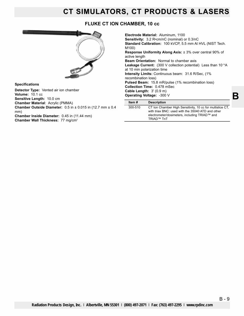
BSpecificationsDetector Type: Vented air ion chamberVolume: 10.1 ccSensitive Length: 10.0 cmChamber Material: Acrylic (PMMA)Chamber Outside Diameter: 0.5 in ± 0.015 in (12.7 mm ± 0.4mm)Chamber Inside Diameter: 0.45 in (11.44 mm)Chamber Wall Thickness: 77 mg/cm2
FLUKE CT ION CHAMBER, 10 cc
Item # Description300-510 CT Ion Chamber High Sensitivity, 10 cc for multislice CT,
with triax BNC: used with the 35040 ATD and otherelectrometer/dosimeters, including TRIAD™ andTRIAD™ TnT
Electrode Material: Aluminum, 1100Sensitivity: 3.2 R•cm/nC (nominal) or 0.3/nCStandard Calibration: 100 kVCP, 5.5 mm Al HVL (NIST Tech.M100)Response Uniformity Along Axis: ± 3% over central 90% ofactive lengthBeam Orientation: Normal to chamber axisLeakage Current: (300 V collection potential) Less than 10-14Aat 10 min polarization time Intensity Limits: Continuous beam: 31.6 R/Sec, (1%recombination loss)Pulsed Beam: 15.8 mR/pulse (1% recombination loss)Collection Time: 0.478 mSecCable Length: 3' (0.9 m)Operating Voltage: -300 V

B - 10Radiation Products Design, Inc. l Albertville, MN 55301 l (800) 497-2071 l Fax: (763) 497-2295 l www.rpdinc.com
B
CT SIMULACT SIMULATTORS, CT PRODUCTS & LASERSORS, CT PRODUCTS & LASERSEXRADIN A17 SLICE THERAPY CT CHAMBER
• Fiducial markers identify center and both ends of thecollecting volume providing easy setup in relation to thebeam
• Proven guard design yields stable, precise measurementsand minimizes settling time by creating uniform field lines
• Shell and guard are made of durable, long lasting Shonkaconductive plastic
• Use of homogeneous material throughout the chamberminimizes perturbation of the beam due to the presence ofthe chamber and optimizes measurements
• Axially symmetric design of the chamber provides anuniform, isotropic response
• Inherent waterproof construction eliminates need foradditional protective coverings
• The Model A17 Exradin Slice Therapy Chamber has aninherent 60Co buildup cap built into its wall thickness forair calibrations and measurements
• Ionization collection efficiency is 99.9% or better • Collecting volume is 1.91 cc
CT ion chambers combine robust design with uniform energyresponse for high energy MV applications.
For performing measurements necessary for calculatingCTDI (CT dose index)The Model A17 Exradin Slice Therapy Chamber is designed fortomotherapy applications. This chamber is useful for weekly QAchecks or patient dose verification with phantoms or water tanksetups. It has excellent response uniformity over the central 8 cmof the chamber length, with variation less than plus or minus 1.5%.
Fast, Precise MeasurementsIts waterproof construction makes it ideal for checking theconsistency of beams at various jaw widths. The chamber ventsthrough a flexible tube that surrounds the triaxial cable, ensuringthe collecting volume is in pressure equilibrium with thesurroundings. The design assures there are no stem or voltagesoakage effects, providing precise and reliable measurements.
Durable Construction, Built to LastThe Model A17 Exradin Slice Therapy Chamber is constructed ofrugged C552 Shonka air-equivalent plastic, providing excellentconductivity and years of reliable use.
SpecificationsCollecting Volume: 1.91 cm3
Collecting Volume Length: 8.0 cm Collector Diameter: 2.4 mm Body Tube Outside Diameter: 12.7 mm Wall Thickness: 3.3 mm Chamber Length: 17.0 cm Body Tube and Guard Material: Shonka air-equivalent plasticC552 Response Uniformity Over the Central 8.0cm of ChamberLength: ±1.5% Collector Material: Carbon fiber Electrical Power Requirements: Operates at ±300 VDC Nominal Collection Efficiency: 100% Maximum Polarizing Potential: 1000 V Nominal Inherent Leakage Currents: 10-15 ALow-Noise Triaxial Cable: 50 ohms, 29 pF/ft, 1.5 m long Signal Connector: Triaxial BNC plug (2-Lug, male pin); othersavailable upon request Waterproof: Yes Product Standards: CE0413, Designed to meet IEC 60601-1, IEC61674
Item Description300-540 CT Chamber, Exradin A17 Slice Therapy
Exradin A17 Schematic

B - 11
CT SIMULACT SIMULATTORS, CT PRODUCTS & LASERSORS, CT PRODUCTS & LASERS
Radiation Products Design, Inc. l Albertville, MN 55301 l (800) 497-2071 l Fax: (763) 497-2295 l www.rpdinc.com
B
Fast, Precise MeasurementsModel A101 is ideal for checking the consistency of beams atvarious jaw widths. The chamber is vented to the ambient,ensuring the collecting volume is in pressure equilibrium with thesurroundings. The design assures there are no stem or voltagesoakage effects, providing precise and reliable measurements.
Durable Construction, Built to LastThe Model A101 CT Chamber is constructed of rugged C552Shonka air-equivalent plastic, providing excellent conductivity andyears of reliable use.
SpecificationsCollecting Volume: 4.54 cm3
Collecting Volume Length: 10.0 cm Collector Diameter: 2.4 mm Body Tube Outside Diameter: 10.0 mm Wall Thickness: 1.0 mm Chamber Length: 164.3 mm Body Tube and Guard Material: Shonka air-equivalent plasticC552 Response Uniformity Over the Central 10 cm of ChamberLength: ±3% Energy Response: 80 kVp to 150 kVp ±4% Collector Material: Carbon fiber Electrical Power Requirements: Operates at ±300 VDC Nominal Collection Efficiency: 100% Maximum Polarizing Potential: 1000 V Nominal Inherent Leakage Currents: 10-15 ALow-Noise Triaxial Cable: 50 ohms, 29 pF/ft, 1.5 m long Included Adapter Sleeve: Wall thickness of 1.3 mm; constructedof PMMASignal Connector: Triaxial BNC plug (2-Lug, male pin); othersavailable upon request Waterproof: No Product Standards: CE0413, Designed to meet IEC 60601-1, IEC61674
EXRADIN A101 CT CHAMBER
• Fiducial markers identify center and both ends of thecollecting volume providing easy setup in relation to the beam
• Proven guard design yields stable, precise measurementsand minimizes settling time by creating uniform field lines
• Shell and guard are made of durable, long lasting Shonkaconductive plastic
• Use of homogeneous material throughout the chamberminimizes perturbation of the beam due to the presence ofthe chamber and optimizes measurements
• Axially symmetric design of the chamber provides anuniform, isotropic response
• Ionization collection efficiency is 99.9% or better• Collecting volume is 4.54 cc
Uncompromising QualityCT ion chambers combine robust design with uniform energyresponse for low energy kVCT applications.
For Performaing Measurements Necessary For CalculatingCTDI (CT Dose Index)The Exradin Model A101 CT Ion Chamber is designed to performthe measurements necessary for calculating the CTDI (computedtomography dose index) as described in the AAPM TG 74, QualityControl in Diagnostic Radiology. The chamber is 10 mm indiameter and comes with an acrylic sheath for use with phantomsthat have the typical 13.1 mm cavity. It has excellent responseuniformity over the central 10 cm of the chamber length, withvariation less than plus or minus 3%.
Exradin A101 Schematic
Item #300-550
DescriptionExradin A101 CT Chamber

B - 12
CT SIMULACT SIMULATTORS, CT PRODUCTS & LASERSORS, CT PRODUCTS & LASERS
Radiation Products Design, Inc. l Albertville, MN 55301 l (800) 497-2071 l Fax: (763) 497-2295 l www.rpdinc.com
B
Vented cylindrical pencil chamber for dose length productmeasurements in computed tomography
• Pencil type chamber for measurements free in air• Provides a sensitive measuring length of 30 cm• Shows a homogeneous response over the whole chamber
length
The CT chamber is a vented cylinder chamber designed for doselength product and dose length product rate measurements incomputed tomography according to the amendment to IEC60601-2-44.
Vented cylindrical pencil chamber for dose length productmeasurements in computed tomography
• Pencil type chamber for measurements within a CT head orbody phantom or free in air
• Provides a sensitive measuring length of 10 cm• Shows a homogeneous response over the whole chamber
length
The CT chamber is a vented cylinder chamber designed for doselength product and dose length product rate measurements incomputed tomography. The chamber allows the determination ofthe CTDI1001, CTDIW2 and CTDIVol3 according to IEC 61223-2-6and IEC 61223-3-5.
1CTDI100 = Computed Tomography Dose Index 1002CTDIW = Weighted CTDI1003CTDIVol = Volume CTDIW
PTW CT CHAMBERS
PTW 30009 CT CHAMBER
PTW 30017 CT CHAMBER
Item Description300-560 PTW 30009 CT Chamber, 3.14 cc
Item Description300-565 PTW 30017 CT Chamber, 9.3 cc
Specifications Item 300-560 Item 300-565PTW ModelType of ProductApplicationMeasuring Quantity
30009 30017Vented pencil type chamberDosimetry in computed tomographyAir kerma length product, exposure length product
Nominal SensitiveVolume
3.14 cm3 9.3 cm3
Reference RadiationQuality
120 kV, HVL 8.4 mm Al (RQT9)
DesignReference PointDirection of Incidence
Not waterproof, vented,pencil typeChamber centerRadial
Nominal Response 14 nC/(Gy.cm) 13 nC/(Gy.cm)
Chamber Voltage -100 V nominal± 500 V maximalhigh voltage to be connected only with activecurrent-limiting device (Imax< 0.5 mA)
Energy Response ≤ ±5% for 70 - 150 kV ≤ ±5% for 50 - 150 kVLeakage Current ≤ ±10 fACable Leakage ≤ 1pC/(Gy.cm)Materials and MeasuresWall Material 1 mm PMMA, graphite coated
Wall Area Density 119 mg/cm2
Dimension ofSensitive Volume
Radius 3.5 mmLength 100 mm
Radius 3.5 mmLength 300 mm
Wall Area Density 119 mg/cm2
Electrode Al tube, graphited outer diameter 3 mm
Ion Collection Time 274 μsMax. Dose Rate for≥≥95.0% saturation
12.4 Gy/s
Ion Collection Efficiency at Nominal Voltage
Max. Dose Per Pulsefor ≥≥95.0% saturation
2.26 mGy
Useful Ranges
Chamber VoltageRadiation QualityTemperature
± 100 - 400 V50 - 150 kV electrons10° to 40° C, 50° to 104° F
Humidity 10 to 80%, max 20 g/m3
Air Pressure 700 - 1060 hPa

B - 13
CT SIMULACT SIMULATTORS, CT PRODUCTS & LASERSORS, CT PRODUCTS & LASERS
Radiation Products Design, Inc. l Albertville, MN 55301 l (800) 497-2071 l Fax: (763) 497-2295 l www.rpdinc.com
B
• Usable on all CT scanners• Head and abdominal configurations included• Made from acrylic with a density of 1.19 gm/cc• Includes 10 PMMA plugs• 1.31 cm inside hole dia. sized for standard CT Dose probes• Rugged foam lined carrying case included
The CT Dose Phantom consists of two 15 cm thick Solid PMMAdisks measuring 16 cm (head) and 32 cm (body) in diameter.
The disks have five through-holes with an inside diameter of 1.31cm to accommodate standard CT dose probes and five acrylicrods to plug the holes not in use. One hole is at center and fourare around the perimeter, 90° apart and 1 cm from hole center tothe outside edge of the phantom.
The head and body phantoms along with the ten acrylic rod plugsare packaged in an extremely rugged foam lined carrying case.
CT DOSE PHANTOMAcrylic
Item Description682-005 CT Dose Phantom, Acrylic
B - 14
CT SIMULACT SIMULATTORS, CT PRODUCTS & LASERSORS, CT PRODUCTS & LASERS
Radiation Products Design, Inc. l Albertville, MN 55301 l (800) 497-2071 l Fax: (763) 497-2295 l www.rpdinc.com
B
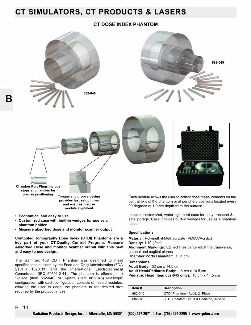
• Economical and easy to use• Customized case with built-in wedges for use as a
phantom holder• Measure absorbed dose and monitor scanner output
Computed Tomography Dose Index (CTDI) Phantoms are akey part of your CT Quality Control Program. MeasureAbsorbed Dose and monitor scanner output with this newand easy to use design.
The Gammex 468 CDTI Phantom was designed to meetspecifications outlined by the Food and Drug Administration (FDA21CFR 1020.33) and the International ElectrotechnicalCommission (IEC 60601-2-44). The phantom is offered as a2-piece (Item 682-040) or 3-piece (Item 862-045) telescopicconfiguration with each configuration consists of nested modules,allowing the user to adapt the phantom to the desired sizerequired by the protocol in use.
CT DOSE INDEX PHANTOM
Each module allows the user to collect dose measurements on thecentral axis of the phantom or at periphery positions located every90 degrees at 1.0-cm depth from the surface.
Includes customized, water-tight hard case for easy transport &safe storage. Case includes built-in wedges for use as a phantomholder.
SpecificationsMaterial: Polymethyl-Methacrylate (PMMA/Acrylic)Density: 1.19 g/cm2
Alignment Markings: Etched lines centered at the transverse,coronal and sagittal planesChamber Ports Diameter: 1.31 cmDimensionsAdult Body: 32 cm x 14.5 cmAdult Head/Pediatric Body: 16 cm x 14.5 cmPediatric Head (Item 682-045 only): 10 cm x 14.5 cm
682-040
682-045
Item #682-040
DescriptionCTDI Phantom - Adult, 2 -Piece
682-045 CTDI Phantom -Adult & Pediatric, 3-Piece
Chamber Port Plugs includestops and handles forprecise positioning Tongue and groove design
provides fast setup timesand ensures precise
module alignment

B - 15
CT SIMULACT SIMULATTORS, CT PRODUCTS & LASERSORS, CT PRODUCTS & LASERS
Radiation Products Design, Inc. l Albertville, MN 55301 l (800) 497-2071 l Fax: (763) 497-2295 l www.rpdinc.com
B
CT DOSE PHANTOM
• Abdominal and Adult Head configurations• PMMA disks and plugs with density of 1.10 g/cc• 1.31 cm diameter holes sized for standard CT Dose probes• Nesting PMMA disks minimize storage space• Compatible with all CT scanners
For all computed tomography systems, the Food and Drug Administrationrecommends measuring the CT Dose Index. Each section of the CIRS CTDose Phantom can provide separate dose information. The user can alsomeasure maximum, minimum and mid-range values of the nominaltomographic section thickness when performing dose profilemeasurements.
The CT Dose Phantom consists of a set of a nesting 15 cm thick solidPMMA disks measuring 16 cm (head) and 32 cm (body) in diameter. Theadult head disk is also suitable for pediatric body measurements. Handleson the body and head are provided for ease in handling andmaneuverability.
Through holes measuring 1.31 cm in diameter will accommodate standardCT probes. Acrylic rods are provided to plug the holes when not in use. Theacrylic rods are machined to receive 1 mm diameter TLD rods.
The CT Dose Phantom is manufactured to comply with the FDA’sperformance standard, 21 CFR 1020.33 that details the measurementrequirements.
An optional Support Bracket can be used to suspend the CT DosePhantom above the imaging couch and align it along the axis of X-ray tuberotation. This enables the phantom to be used to assess CT dose in helicalmode or any mode that requires the extended travel of the imaging couchor a wide beam. This set-up might be used to address the dosimetryapproach described in TG111. An additional application of the supportbracket is to provide a body to simulate continous scatter radiation from thepatient during helical CT for dose safety measurements inside and outsidethe exam room.
Replacement acrylic rods are available in 14, 15 or 16 cm long.
Item 682-007 CT Dose Phantom Includes(1) Abdominal Cylinder(1) Adult Head Cylinder(9) Acrylic Rods
SpecificationsOverall Dimensions: 12.5" x 12.5" x 5.5" (31.8 x 31.8 x 15 cm)Weight: 29 lb (13 kg)Materials: PMMA
(1) Foam Lined Carry Case(1) User Guide(1) 48 Month Warranty
Item #682-007
DescriptionCT Dose Phantom
682-009 CT Dose Phantom Support Bracket, Optional682-007-14 Acrylic Rod CT Probe, 1.31cm Dia. x 14cm Long682-007-15 Acrylic Rod CT Probe, 1.31cm Dia. x 15cm Long 682-007-16 Acrylic Rod CT Probe, 1.31cm Dia. x 16cm Long
682-007-14, 682-007-15 and 682-007-16
HEAD/BODY CT PHANTOM
• Head Module of a uniform disc of Solid Water® Material • Ring of Bone mimicking material that mounts around the head
module is included• Body scanning module, body annulus is mounted on the head
module.• The head has 5 tapered cavities which accept tapered inserts and
the body annulus ring has 4 cavities, providing a total of 9 test positions.
The Head/Body CT Phantom provides a set of tools for evaluating CTimage quality. The main modules are constructed of Solid Water®. Thispermits testing without the difficulties of filling phantoms with water. The setof standard inserts is sufficient for many users. The Head/Body CTPhantom comes complete with a custom carrying case.
SpecificationsPhantom Construction: Solid Water® MaterialInserts Included:(9) Uniform Solid Water® inserts for measurement of Noise,
CT Number, and Uniformity(1) Edge/Contrast Scale Response(1) Spatial Resolution (1.50 to 0.4 mm at 100% contrast)(1) Low Contrast Detectability (0.6%)(1) Alignment Artifact (Aluminum Pin)(4) Alignment, Slice Thickness, Phantom Position(2) Slice Thickness and Sensitivity Profile 2:1 Slope (26.6° Slope)(2) Beam Hardening Artifact (Simulated Bone)(6) LinearityCase Size: 24" x 16" x 8" (70 x 41 x 22 cm)Weight: 35.7 lb (16.2 kg)
Item #682-461
DescriptionHead/Body CT Phantom

B - 16
CT SIMULACT SIMULATTORS, CT PRODUCTS & LASERSORS, CT PRODUCTS & LASERS
Radiation Products Design, Inc. l Albertville, MN 55301 l (800) 497-2071 l Fax: (763) 497-2295 l www.rpdinc.com
B
CT ELECTRON DENSITY PHANTOMCreate CT-to-density tables with ease for TPS commissioning
• Cover a wide range of electron density values• Help ensure accurate calculations of dose distributions
The American Association of Physicists in Medicine1 (AAPM) andInternational Atomic Energy Agency2 (IAEA) report that TreatmentPlanning Systems (TPS) convert Hounsfield Units (HUs) to electrondensities for accurate calculations of dose distributions. This is commonlydone using electron density reference materials that enable the verificationprocedure.
The only Solid Waterfi Insert HolderThe CT Electron Density Phantom consists of a zero HU Solid Water® diskthe size of an average pelvis. Sixteen insert chambers in the disk aredesigned to be used with interchangeable Tissue Mimicking Materials(TMM), used for characterization. Our standard Electron Density Insert Setincludes 13 different materials with a wide range of electron density values.Use the electron density inserts to create CT-todensity tables needed forTPS commissioning. The Solid Water disk also contains eight, 1mmdiameter holes spaced at 50 mm intervals around the center of thephantom to test the geometric accuracy of the CT scanner. The same SolidWater disk can be used for calcium and iodine inserts to evaluate the DualEnergy characteristics of CT scanners.
SpecificationsDisk Material: Zero HU Solid Water®Size: 12.9" Dia x 2" H (33 x 5 cm)Geometric Accuracy Testing: 1mm diameter holes spaced at50 mm intervals
WeightDisk and Standard Inserts: 10 lb (4.6 kg)Phantom with case: 14.5 lb (6.6 kg)Warranty: One year
1 American Association of Physicists in Medicine Radiation Therapy Committee Task Group53: Quality Assurance for Clinical Radiotherapy Treatment Planning2 IAEA TECDOC-1583. Commissioning of Radiotherapy Treatment Planning Systems: Testing forTypical External Beam Treatment Techniques
Lung (LN-300)Lung (LN-450)Adipose (AP6)BreastZero HU Solid Water (x4)
Optional Titanium (Grade 2)
BrainLiver (LV1)Inner BoneBone (B200)Bone (CB2-30% Mineral)Bone (CB2-50% Mineral)Cortical Bone (SB3)
True Water
0.290.400.900.960.99
3.79
1.051.071.091.111.281.471.69
1.00
0.300.450.920.991.02
4.51
1.051.081.121.151.341.561.82
1.00
Tissue Mimicking Insert Electron DensityRelative to Water
Physical Densityg/cm3
Optional Stainless Steel (Type 316) 6.58 8.00
Optional Aluminum (1100-H14) 2.36 2.71
Item #682-467
DescriptionCT Electron Density Phantom
682-468 Titanium Insert, Optional
682-469 Stainless Steel Insert, Optional
682-470 Aluminum Insert, Optional

B - 17
CT SIMULACT SIMULATTORS, CT PRODUCTS & LASERSORS, CT PRODUCTS & LASERS
Radiation Products Design, Inc. l Albertville, MN 55301 l (800) 497-2071 l Fax: (763) 497-2295 l www.rpdinc.com
B
ELECTRON DENSITY PHANTOMCorrelate CT Number and Tissue Electron Density
The Electron Density Phantom consists of two nested disks madefrom Plastic Water®-LR. They can represent both head andabdomen configurations. Nine different tissue equivalent electrondensity plugs can be positioned at 17 different locations within thescan field. Included is a water vial plug that can be filled with anyfluid. Optional distance marker plugs enable quick assessment ofthe CT scanner’s distance measurement accuracy
SpecificationsOverall Dimensions
Electron Density Head Insert: 7" Dia x 1.97" D (180 x 50 mm)Electron Density Body without Head Insert:12" W x 10.7" H x 1.97" D (330 x 270 x 50 mm)
WeightsElectron Density Head Insert: approx 2 lb (0.950 kg)Electron Density Body without Head Insert: approx 4.7 lb(2.1 kg)
Materials: Water and Tissue Equivalent Epoxy Materials
Item #682-062
DescriptionElectron Density Phantom
• Evaluate CT scan data• Correct for inhomogeneities• Document relationship between CT number and tissue
electron density• Simulate indicated tissue within the diagnostice energy
range• Quick assessment of distance registration
Because CT scans are used to correct for tissue inhomogeneitiesin radiotherapy treatment planning, it is important to obtain aprecise relationship between CT number (in Housfield units) andelectron densities. The Electron Density Phantom enables precisecorrelation of CT data to electron density of various tissues. Thephantom is manufactured from CIRS Tissue Equivalent Materials.
Description *PhysicalDensity, (g/cc)
Electron Densityx 1023 Electrons/cc
RED(Relative to H2O)
Electron Density Head Insert
Qty
1 1.029 3.333 0.998
Lung (Inhale) Equivalent Electron Density Plug2 0.20 0.634 0.190
Lung (Exhale) Equivalent Electron Density Plug2 0.50 1.632 0.489
Breast (50% Gland / 50% Adipose) Equivalent Electron Density Plug2 0.99 3.261 0.976Solid Trabecular Bone (200 mg/cc HA) Equivalent Electron Density Plug2 1.16 3.730 1.117Liver Equivalent Electron Density Plug2 1.07 3.516 1.052Muscle Equivalent Electron Density Plug2 1.06 3.483 1.043Adipose Equivalent Electron Density Plug2 0.96 3.171 0.949Solid Dense Bone (800mg/cc HA) Equivalent Electron Density Plug2 1.53 4.862 1.456Solid Dense Bone (1250mg/cc HA) Equivalent Electron Density Plug1 1.82 5.663 1.695Water-fillable Electronic Density Plug (Real water data provided)1 1.00 3.340 1.000
Electron Density Body without Head Insert1 1.029 3.333 0.998
Set of 2 Feet for 682-0621Soft Carry Case1User Guide148 Month Warranty1
ELCTRON DENSITY PHANTOM ITEM 682-062 INCLUDES
B - 18
CT SIMULACT SIMULATTORS, CT PRODUCTS & LASERSORS, CT PRODUCTS & LASERS
Radiation Products Design, Inc. l Albertville, MN 55301 l (800) 497-2071 l Fax: (763) 497-2295 l www.rpdinc.com
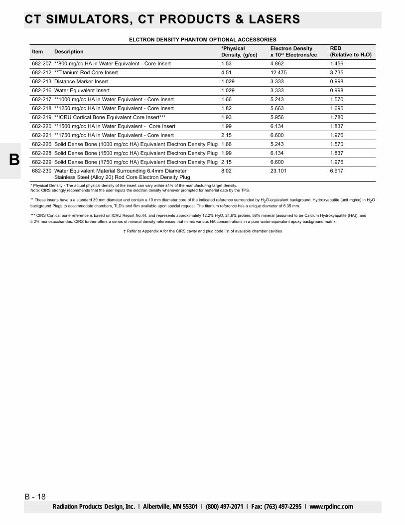
B* Physical Density - The actual physical density of the insert can vary within ±1% of the manufacturing target density.Note: CIRS strongly recommends that the user inputs the electron density whenever prompted for material data by the TPS.
** These inserts have a a standard 30 mm diameter and contain a 10 mm diameter core of the indicated reference surrounded by H2O-equivalent background. Hydroxyapatite (unit mg/cc) in H2Obackground Plugs to accommodate chambers, TLD’s and film available upon special request. The titanium reference has a unique diameter of 6.35 mm.
*** CIRS Cortical bone reference is based on ICRU Report No.44, and represents approximately 12.2% H2O, 24.6% protein, 58% mineral (assumed to be Calcium Hydroxyapatite (HA)), and5.2% monosaccharides. CIRS further offers a series of mineral density references that mimic various HA concentrations in a pure water-equivalent epoxy background matrix.
† Refer to Appendix A for the CIRS cavity and plug code list of available chamber cavities
Description *PhysicalDensity, (g/cc)
Electron Densityx 1023 Electrons/cc
RED(Relative to H2O)Item
**800 mg/cc HA in Water Equivalent - Core Insert682-207 1.53 4.862 1.456**Titanium Rod Core Insert682-212 4.51 12.475 3.735
ELCTRON DENSITY PHANTOM OPTIONAL ACCESSORIES
Distance Marker Insert682-213 1.029 3.333 0.998Water Equivalent Insert682-216 1.029 3.333 0.998**1000 mg/cc HA in Water Equivalent - Core Insert682-217 1.66 5.243 1.570**1250 mg/cc HA in Water Equivalent - Core Insert682-218 1.82 5.663 1.695**ICRU Cortical Bone Equivalent Core Insert***682-219 1.93 5.956 1.780**1500 mg/cc HA in Water Equivalent - Core Insert682-220 1.99 6.134 1.837**1750 mg/cc HA in Water Equivalent - Core Insert682-221 2.15 6.600 1.976Solid Dense Bone (1000 mg/cc HA) Equivalent Electron Density Plug682-226 1.66 5.243 1.570Solid Dense Bone (1500 mg/cc HA) Equivalent Electron Density Plug682-228 1.99 6.134 1.837Solid Dense Bone (1750 mg/cc HA) Equivalent Electron Density Plug682-229 2.15 1.9766.600Water Equivalent Material Surrounding 6.4mm DiameterStainless Steel (Alloy 20) Rod Core Electron Density Plug
682-230 8.02 6.91723.101
B - 19
CT SIMULACT SIMULATTORS, CT PRODUCTS & LASERSORS, CT PRODUCTS & LASERS
Radiation Products Design, Inc. l Albertville, MN 55301 l (800) 497-2071 l Fax: (763) 497-2295 l www.rpdinc.com
B
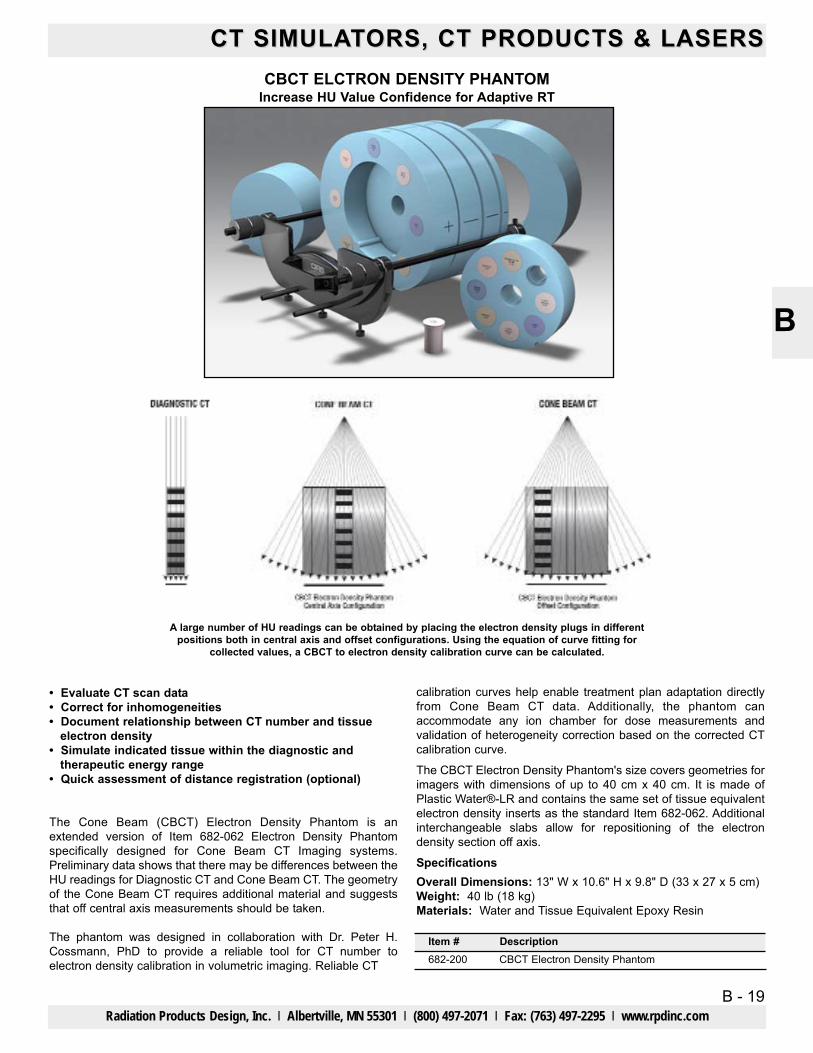
CBCT ELCTRON DENSITY PHANTOMIncrease HU Value Confidence for Adaptive RT
calibration curves help enable treatment plan adaptation directlyfrom Cone Beam CT data. Additionally, the phantom canaccommodate any ion chamber for dose measurements andvalidation of heterogeneity correction based on the corrected CTcalibration curve.
The CBCT Electron Density Phantom's size covers geometries forimagers with dimensions of up to 40 cm x 40 cm. It is made ofPlastic Water®-LR and contains the same set of tissue equivalentelectron density inserts as the standard Item 682-062. Additionalinterchangeable slabs allow for repositioning of the electrondensity section off axis.
SpecificationsOverall Dimensions: 13" W x 10.6" H x 9.8" D (33 x 27 x 5 cm)Weight: 40 lb (18 kg)Materials: Water and Tissue Equivalent Epoxy Resin
A large number of HU readings can be obtained by placing the electron density plugs in differentpositions both in central axis and offset configurations. Using the equation of curve fitting for
collected values, a CBCT to electron density calibration curve can be calculated.
• Evaluate CT scan data• Correct for inhomogeneities• Document relationship between CT number and tissue
electron density• Simulate indicated tissue within the diagnostic and
therapeutic energy range• Quick assessment of distance registration (optional)
The Cone Beam (CBCT) Electron Density Phantom is anextended version of Item 682-062 Electron Density Phantomspecifically designed for Cone Beam CT Imaging systems.Preliminary data shows that there may be differences between theHU readings for Diagnostic CT and Cone Beam CT. The geometryof the Cone Beam CT requires additional material and suggeststhat off central axis measurements should be taken.
The phantom was designed in collaboration with Dr. Peter H.Cossmann, PhD to provide a reliable tool for CT number toelectron density calibration in volumetric imaging. Reliable CT
Item #682-200
DescriptionCBCT Electron Density Phantom
B - 20
CT SIMULACT SIMULATTORS, CT PRODUCTS & LASERSORS, CT PRODUCTS & LASERS
Radiation Products Design, Inc. l Albertville, MN 55301 l (800) 497-2071 l Fax: (763) 497-2295 l www.rpdinc.com
B
Description PhysicalDensity (g/cc)
Electron DensityPer cc x 1023
RED(Relative to H2O)
Electron Density Head Insert
Qty
1 1.029 3.333 0.998
Lung (Inhale) Equivalent Electron Density Plug2 0.20 0.634 0.190Lung (Exhale) Equivalent Electron Density Plug2 0.50 1.632 0.489Breast (50% Gland / 50% Adipose) Equivalent Electron Density Plug2 0.99 3.261 0.976Solid Trabecular Bone (200 mg/cc HA) Equivalent Electron Density Plug2 1.16 3.730 1.117Liver Equivalent Electron Density Plug2 1.07 3.516 1.052Muscle Equivalent Electron Density Plug2 1.06 3.483 1.043Adipose Equivalent Electron Density Plug2 0.96 3.171 0.949Solid Dense Bone (800 mg/cc HA) Equivalent Electron Density Plug2 1.53 4.862 1.456
Water-fillable Electronic Density Plug (Real water data provided)1 1.00 3.34 1.00
1 1.029 3.333 0.99850 mm Thick Bolus Slab2
Electron Density Body without Head Insert1 1.029 3.333 0.998
111
100 mm L x 30 mm dia Background Equivalent Plug12.5 mm Thick Bolus Slab37.5 mm Thick Bolus SlabCBCT Electron Density Phantom -Annulus (100 mm Thick)
1.029 3.333 0.9981.029 3.333 0.9981.029 3.333 0.9981.029 3.333 0.998
1 CBCT Electron Density Phantom-Annulus Solid Insert (100 mm Thick) 1.029 3.333 0.9981 Holder/Support set for 682-200 & Model 062MQA1 Soft Carry Case for 682-2001 User Guide1 48 Month Warranty
Solid Dense Bone (1250 mg/cc HA) Equivalent Electron Density Plug1 1.82 5.663 1.695
1 1.029 3.333 0.998Set of 2 Feet for 682-0621 1.029 3.333 0.998Soft Carry Case for 680-062
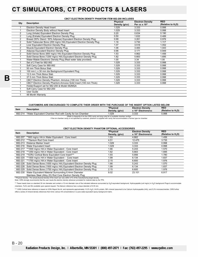
CBCT ELECTRON DENSITY PHANTOM ITEM 682-200 INCLUDES
Description *PhysicalDensity, (g/cc)
Electron Densityx 1023 Electrons/cc
RED(Relative to H2O)Item
†Water Equivalent Chamber Rod with Cavity for Ion Chamber682-214 1.029 3.333 0.998
CUSTOMERS ARE ENCOURAGED TO COMPLETE THEIR ORDER WITH THE PURCHASE OF THE INSERT OPTION LISTED BELOW
†Refer to Appendix A for the CIRS cavity and plug code list of available chamber cavities.If the ion chamber cavity is not specified by customer, phantom is supplied with cavity that accommodates a Farmer type ion chamber.
* Physical Density - The actual physical density of the insert can vary within ±1% of the manufacturing target density.Note: CIRS strongly recommends that the user inputs the electron density whenever prompted for material data by the TPS.
** These inserts have a a standard 30 mm diameter and contain a 10 mm diameter core of the indicated reference surrounded by H2O-equivalent background. Hydroxyapatite (unit mg/cc) in H2O background Plugs to accommodatechambers, TLD’s and film available upon special request. The titanium reference has a unique diameter of 6.35 mm.
*** CIRS Cortical bone reference is based on ICRU Report No.44, and represents approximately 12.2% H2O, 24.6% protein, 58% mineral (assumed to be Calcium Hydroxyapatite (HA)), and 5.2% monosaccharides. CIRS furtheroffers a series of mineral density references that mimic various HA concentrations in a pure water-equivalent epoxy background matrix.
Description *PhysicalDensity, (g/cc)
Electron Densityx 1023 Electrons/cc
RED(Relative to H2O)Item
**800 mg/cc HA in Water Equivalent - Core Insert682-207 1.53 4.862 1.456**Titanium Rod Core Insert682-212 4.51 12.475 3.735
CBCT ELECTRON DENSITY PHANTOM OPTIONAL ACCESSORIES
Distance Marker Insert682-213 1.029 3.333 0.998Water Equivalent Insert682-216 1.029 3.333 0.998**1000 mg/cc HA in Water Equivalent - Core Insert682-217 1.66 5.243 1.570**1250 mg/cc HA in Water Equivalent - Core Insert682-218 1.82 5.663 1.695**ICRU Cortical Bone Equivalent Core Insert***682-219 1.93 5.956 1.780**1500 mg/cc HA in Water Equivalent - Core Insert682-220 1.99 6.134 1.837**1750 mg/cc HA in Water Equivalent - Core Insert682-221 2.15 6.600 1.976Solid Dense Bone (1000 mg/cc HA) Equivalent Electron Density Plug682-226 1.66 5.243 1.570Solid Dense Bone (1500 mg/cc HA) Equivalent Electron Density Plug682-228 1.99 6.134 1.837Solid Dense Bone (1750 mg/cc HA) Equivalent Electron Density Plug682-229 2.15 1.9766.600Water Equivalent Material Surrounding 6.4mm DiameterStainless Steel (Alloy 20) Rod Core Electron Density Plug
682-230 8.02 6.91723.101

B - 21
CT SIMULACT SIMULATTORS, CT PRODUCTS & LASERSORS, CT PRODUCTS & LASERS
Radiation Products Design, Inc. l Albertville, MN 55301 l (800) 497-2071 l Fax: (763) 497-2295 l www.rpdinc.com
B
GILLIAN QA PHANTOMEvaluate Image Distortion and Alignment in SPECT/CT, PET/CT and MRI
Transverse SPECT of Phantom
Misalignment detail
CT Image SPECT Image Combined Imageshowing verticle
misalignment
Combined Imageshowing more
serious alignmentproblem
• Compatible with SPECT/CT, PET/CT and MRI• Check alignment and distortion across the entire imaging
field• Easy to fill and drain• Allows for independent assessment of equipment function• Simple geometry allows for quick visual interpretation
Hybrid scanning systems such as SPECT/CT and PET/CT are increasinglybeing used to improve tumor identification, treatment delivery and monitortreatment effectiveness. By combining images from two different imagingmodalities, hybrid scanning systems take advantage of the strengths ofindividual imaging modalities while minimizing their respectiveweaknesses. Proper alignment of the fused images is an ongoing concern.
The Gillian QA Phantom provides a simple and cost effective solution toverify image alignment and distortion. The phantom consists of a watertight acrylic cylinder that can be filled with a variety of fluids. Four non-parallel rods of varying diameter run the entire length of the cylinder.Images produced with the phantom can quickly and clearly show if there isany mismatch in the fused images.
Gillian QA Phantom Includes(1) Gillian QA Phantom(1) Fill Plug(1) Drain Adapter(1) Vent Port(1) Carry Handle with Strap(1) User Guide48 Month Warranty
SpecificationsOverall Dimensions: 10" x 10.75" x 16" (25.4 x 27.3 x 40.7 cm)Weight: 14 lb (6.4 kg)Materials: AcrylicRod Diameters: 0.5", 0.75", 0.87" and 1.26" (12.75, 19, 22 and 32 mm)
Item #682-850
DescriptionGillian QA Phantom

B - 22
CT SIMULACT SIMULATTORS, CT PRODUCTS & LASERSORS, CT PRODUCTS & LASERS
Radiation Products Design, Inc. l Albertville, MN 55301 l (800) 497-2071 l Fax: (763) 497-2295 l www.rpdinc.com
B
AAPM CT PERFORMANCE PHANTOMMeets guidelines in AAPM Report #1 “Performance Evaluation and Quality Assurance of CT Scanners”
Measurement Capability• Noise• Sensitivity / Detectability• Mechanical Alignment• Beam Hardening• Slice Thickness
(Shown with optional low contrast insert.)
• Size Independence• Radiation Dose• Spatial Uniformity• HU Linearity• Spatial Resolution & line spread
function
Item #682-014682-015682-021
DescriptionTLD InsertLow Contrast Insert - Spherical TargetsCarrying Case
The AAPM CT Performance Phantom offers the user a single test objectthat measures ten distinct CT performance parameters. The phantomdesign is based on the guidelines presented in Report #1 of the AmericanAssociation of Physicists in Medicine Task Force on CT ScannerPhantoms. The goals of report #1 were to “(1) define ‘performance’ of a CTscanner and (2) describe methods of performance testing throughutilization of particular phantoms.” A CT number linearity insert, high contrast resolution insert and slice widthinsert are housed in an 8.5" diameter (21.6 cm) PMMA water tank withquick disconnect valves for ease of filling and draining between use. Alsoincluded is a 0.25" (0.64 cm) bone equivalent ring that can be fit over theinserts to evaluate the effects of beam hardening. A contrast test object is adhered to the bottom of the tank that includes tworows of cavities from 1 to 0.125" diameter (2.54 to 0.32 cm). The cavitiescan be filled with various solutions for contrast evaluation. An aluminumalignment insert is incorporated in the lid of the tank and can beinterchanged with a polystyrene TLD insert for dose measurements. A user’s manual, holding cradle, filling tubes and other accessories areincluded. Optional items: Low Contrast Insert, Whole Body Resolutionand Noise Ring, TLD Insert, Low Contrast Insert - Spherical Targets orCarrying Case.
CT Number Linearity Insert7.5" OD x 2.5" L (19.05 x 6.35 cm) includes 1" diameter (2.54 cm)rods of polyethylene, PMMA (acrylic), polycarbonate, polystyrene,and nylon. Density values (g/cc): polyethylene - 0.95, polystyrene- 1.05, nylon - 1.1, acrylic - 1.19, polycarbonate - 1.20.
Resolution Insert7.5" OD x 2.5" L (19.05 x 6.35 cm) with acrylic equivalent testobject with 8 sets of air thru holes (five holes per set): Diameter ofholes is 1.75, 1.5, 1.25, 1.00, 0.75, 0.61, 0.50, and 0.40 mm.Distance between each hole equal to hole diameter. Each row is5 mm apart. Insert also contains a 0.009" (0.023 cm) stainlesssteel wire positioned longitudinally for calculation of line-spreadfunction.
Slice Thickness Insert7.5" OD x 3.5" L (19.05 x 8.89 cm) Contains three 0.02 x 1" (0.064x 2.54 cm) aluminum strips angled at 45°, positioned on centerand aligned vertically.
Alignment Pin0.25" diameter x 3" L (0.64 x 7.62 cm) aluminum pin with threadedattachment to housing cover plate.
Bone Ring7.65" ID x 0.2" wall thickness x 2.8" L (19.43 x 0.5 x 7.1 cm)cortical bone ring. Fits over linearity, resolution and slice thicknessinsert to harden the beam.
Item 682-010 IncludesContrast Test Object(This option is only available with purchase of the phantom body)8.5" OD x 2.5" L (21.6 x 6.35 cm) solid acrylic equivalent disk blockwith 12 fillable cavities 2.25" deep (5.72 cm). Two of each cavitywith diameters: 1, 0.75", 0.50", 0.375", 0.25", and 0.125" (2.54,1.9, 1.27, 0.95, 0.64, 0.32 cm), spaced twice their diameter apartfrom a center line. Cavities can be easily filled from the ouside withdextrose or sodium chloride solutions of various concentration.
ImageUnavailable
User Guide48 month warranty
Item 682-014 TLD Insert0.5" dia. x 3.5" L (1.3 x 8.9 cm) PMMA rod drilled 3" deep (7.6 cm)to accept TLD’s. Can be swapped with Alignment pin in housingcover without removing the cover.
Item 682-012 Low Contrast Insert8" OD x 1.18" L (20.3 x 3 cm) propietary epoxy with CT density6-10 HU above water. The test object contains a series of water-filled holes from 2.5 to 7.5 mm in diameter, in 0.5 mm steps. Foreach target size the center-to-center distance between holes istwice the hole diameter.
Item 682-013 Whole Body Resolution and Noise Ring12" OD x 8.5" ID x 2" L (30.5 x 21.6 x 5.1 cm) fits over phantomhousing and contains the same test object as the ResolutionInsert, at two locations 90° apart.
Item 682-015 Low Contrast Insert- Spherical Targets8" OD x 1.18" L (20.3 x 3 cm) Plastic Water® LR equivalentbackground. The test object contains spheres 5, 10 & 20 CTUabove background and 3 reference plugs for each material usedas spheres.
Optional Accessories
ImageUnavailable
ImageUnavailable
Item 682-021 Carrying Case for 682-010Custom carry case for easy storage and handling ofcomplete Model 610.
Item #682-010682-012682-013
DescriptionAAPM CT Performance PhantomLow Contrast InsertWhole Body Resolution & Noise Ring
SpecificationsOverall Dimensions: 8.5" OD x 15.5" L (21.6 x 39.4 cm)Empty Weight: 17.25 lb (7.9 kg)Materials: PMMA cast tubing 8.5" OD, 8" ID x 12.75" L (21.6 OD, 20.3 IDx 32.4 cm) with removable lid

B - 23
CT SIMULACT SIMULATTORS, CT PRODUCTS & LASERSORS, CT PRODUCTS & LASERS
Radiation Products Design, Inc. l Albertville, MN 55301 l (800) 497-2071 l Fax: (763) 497-2295 l www.rpdinc.com
B
NUALINE LASERS FOR CT AND LINAC ROOMS
• Individual laser line has micro Angular and Transverseadjustments.
• It is extremely easy for installation and routine calibration.Customers may be able to install the lasers withoutprofessional help.
• The laser’s compact size makes it fit any existing lasersystems.
• No tools required.
Item 710-993 GSG1 Green Sagittal LaserThe laser head could pivot in a range of 135° for flexible location(on the ceiling direct above the couch or on a vertical wall).
The laser line has two adjusting knobs. One for tilting laser lineand one for moving laser line transversely. The adjustment istool-less.
Item 710-994 GCR1 Green Crosshair LaserThe laser head could be adjusted over the mounting base for lasercenter alignment.
Each laser line has two adjusting knobs. One for tilting laser lineand one for moving laser line transversely. The adjustment istool-less.
Item 710-995 SG1 Red Sagittal/Backpointer LaserThe laser head could pivot in a range of 135° for flexible location(on the ceiling direct above the couch or on a vertical wall).
The laser head could be adjusted over the mounting base for lasercenter alignment.
The laser line has two adjusting knobs. One for tilting laser lineand one for moving laser line transversely. The adjustment istool-less. This feature brings easiness for both installation and
routing calibration.
This laser (without a line generator lens) could also be used as a back-pointer.
Item 710-997 CR2 Red Crosshair LaserModel CR2 is designed for small treatment rooms with diagonallayout. The laser head has a pivoting range of 135°. No additionalmounting bracket is needed.
Two internal screws for adjusting cross hair line (as a whole)horizontally and vertically. The line titling is done by rotate the laserhead over the mounting base.
Item 710-998 CR3 Red Crosshair LaserThe laser head could be adjusted over the mounting base for lasercenter alignment.
Each laser line has two adjusting knobs. One for tilting laser line and one for moving laser line transversely.
The adjustment is tool-less. This feature brings easiness for both installation and routing calibration.
SpecificationsElectrical power consumption Red laser: <0.2A / 7VDC. Green laser: <1A / 3VDC
FDA ComplianceNualine laser meets FDA requirement of class I medical device.Nualine laser devices are listed with FDA and the company isregistered with FDA. A warning label on the device meets FDAcode 1040.10.
710-998
710-993
710-994
710-997
710-995
Item # 710-993 710-994 710-995
Description Green Sagittal Green Crosshair Red Sagittal/Backpointer
710-997
Red Crosshair
710-998
Red Crosshair
532nm DPSS
Adjustable
532nm DPSS 635nm 635nm 635nmWave LengthLine WidthRangeFocus
< 1 mm < 1 mm < 1 mm < 1 mm < 1 mm
4 -15' (1.2 - 4.5 m) 4 -15' (1.2 - 4.5 m) 6 -12' (1.8 - 3.7 m) 6 -12' (1.8 - 3.7 m) 6 -12' (1.8 - 3.7 m)Adjustable Fixed Fixed Fixed
Model GSG1 GCR1 SG1 CR2 CR3
Size
Weight 15 oz (425 gm)
3" x 5.9" x 2"(7.6 x 15 x 5 cm)
28.3 oz (800 gm) 10.6 oz (300 gm) 12.9 oz (365 gm) 19.5 oz (550 gm)
4" x 5.9" x 1.8"(10.2 x 15 x 4.5 cm)
3.2" x 2.75" x 2.3"(8.1 x 7 x 5.8 cm)
3.5" x 3" x 2.3"(8.9 x 7.6 x 5.8 cm)
4.5" x 4" x 2"(11.4 x 10.2 x 5 cm)

B - 24
CT SIMULACT SIMULATTORS, CT PRODUCTS & LASERSORS, CT PRODUCTS & LASERS
Radiation Products Design, Inc. l Albertville, MN 55301 l (800) 497-2071 l Fax: (763) 497-2295 l www.rpdinc.com
B
LAP ASTOR LASERSLaser Systems for Patient Alignment
ASTOR lasers come standard with adjustable tilting bracketsallowing for rotation up to 45°. Due to its very small size LAP lasersare ideal for mounting in small and hard to reach places.
SpecificationsASTOR RedLine Width Up to 4 m Distance: <1mmLine Length at 3 m / 10 ft Distance: 13.1 ft (4 m)Laser Type: DiodeWavelength: 635 nmOutput Power: <1mWSupply Voltage: 100 - 240 VACInternal Voltage: 5 V DCPower Consumption: 1 WOperating Temperature: 0-40°CDimensions: 7.4" H x 3.4" W x 3.6" D (188 x 86 x 93 mm)Weight: 3.3 lb (1.5 kg)Adjustment Accuracy at Isocenter: ± 0.5 mm
ASTOR GreenLine Width Up to 4 m Distance: <1mmLine Length at 3 m / 10 ft Distance: 10 ft (3 m)Laser Type: Diode Pumped Solid StateWavelength: 532 nmOutput Power: <1mWSupply Voltage: 100 - 240 VACInternal Voltage: 5 V DCPower Consumption: 10 WOperating Temperature: 15-30°CDimensions: 8.7" H x 4.3" W x 4.0" D (221 x 110 x 101 mm)Weight: 5 lb (2.4 kg)Adjustment Accuracy at Isocenter: ± 0.5 mm
Integrated Tiltable Bracket
ASTOR room lasers are high precision tools for patient setupand improved treatment quality.
Precise, accurate and reproducible patient positioning isparamount to the success of radiation therapy treatments.Combined with on board imaging systems the patient positioninglasers provide an interface between the patient and the treatmentdelivery system. Room lasers are necessary tools for aligning thepatient, daily reference isocenter adjustments, and assuringoptimized isocenter accuracy for your linear accelerator.
LAP room lasers are equipped with extremely stable highlypolished and extra flattened plane glass windows. They have avery low and constant dispersion to assure a fine and sharplyedged laser line. The glass is anti-reflective to avoid interferencefrom the beam.
LAP UltraLine® is the result of the advanced mechanical systemsand the unique optoelectronics used to generate and align laserlines for medical applications.
Adjustments ASTOR red room lasers• Rotate vertical and horizontal line• Parallel line translation right/left and up/down• Plane tilt horizontal and vertical (without cover removement)• Focus vertical and horizontal line
ASTOR Green forms a cross by using one singular element: aprism, manufactured to split one beam into two perpendicularlines. This configuration allows LAP ASTOR GREEN room lasersto use one window only. As the beam forming takes place beforethe prism and its surface antireflection coating is selcted for thelaser’s wavelength, focussing of the crosshair has virtually noinfluence on rectangularity or brightness distribution – a realsuperprism. Due to the singular prism, focussing of both lines ofthe laser cross is handled by a single adjustment screw.
Adjustments ASTOR green roomlasers• Rotation clockwise and counterclockwise• Parallel line translation right/left and up/down• Plane tilt horizontal and vertical(without cover removement)• Focus crosshair
711-001711-002711-010
ASTOR Red - CrosshairASTOR Red - LineASTOR Green - Crosshair
711-012 ASTOR Green - Line
711-025711-026
Backpointer Laser - Red Backpointer Laser - Green
Item LAP Lasers
BACKPOINTER LASER
The solid state diode Backpointer laser comes in either red orgreen. The small housing of the red diode Backpointer has beenspecially designed to replace the fiber optic head of the oldergeneration.

B - 25
CT SIMULACT SIMULATTORS, CT PRODUCTS & LASERSORS, CT PRODUCTS & LASERS
Radiation Products Design, Inc. l Albertville, MN 55301 l (800) 497-2071 l Fax: (763) 497-2295 l www.rpdinc.com
B
711-015711-017711-020711-022
APOLLO Red - CrosshairAPOLLO Red - LineAPOLLO Green - CrosshairAPOLLO Green - Line
711-025711-026
Backpointer Laser - Red Backpointer Laser - Green
Item LAP Lasers
LAP APOLLO LASERSLaser Systems for Patient Alignment
APOLLO room lasers are high precision tools for patientsetup and improved treatment quality.
Precise, accurate and reproducible patient positioning isparamount to the success of radiation therapy treatments.Combined with on board imaging systems the patient positioninglasers provide an interface between the patient and the treatmentdelivery system. Room lasers are necessary tools for aligning thepatient, daily reference isocenter adjustments, and assuringoptimized isocenter accuracy for your linear accelerator. The LAPAPOLLO lasers deliver the highest precision, accuracy andreproducibility: with their long lines and 6 degrees of remotecontrolled freedom they are ideally suited for today’s advancedtreatments.
Key points of APOLLO room lasers• Longer laser lines for improved patient positioning • Clockwork precision motors and gears• Full 6 degrees of freedom adjustment via wireless IR RC• Compact design combined with the finest optoelectronics• Superior aluminium construction, extruded and CAM machined
LAP room lasers are equipped with extremely stable highlypolished and extra flattened plane glass windows. They have avery low and constant dispersion to assure a fine and sharplyedged laser line. The glass is anti-reflective to avoid interferencefrom the beam.
LAP APOLLO avoids the pitfalls of two separate lines forming across by using one singular element: a prism, manufactured tosplit one beam into two perpendicular lines. This configurationallows LAP APOLLO room lasers to use one window only, makingthem the most compact systems. As the beam forming takes placebefore the prism, and its surface antireflection coating is selectedfor the laser’s wavelength, focussing of the crosshair has virtuallyno influence on rectangularity or brightness distribution – a realsuperprism. Due to the singular prism, focussing of both lines ofthe laser cross is handled by a single adjustment drive.
During the installation of the treatment machine the APOLLOlasers are adjusted so that their respective laser lines preciselyintersect the isocenter. If over time further adjustments arerequired to achieve accuracy and performance related to the trueisocenter of the treatment machine, the APOLLO lasers offer anadvanced remote controlled system that provides fast and simpleadjustments from a convenient handheld remote control.
FULL FUNCTION REMOTE CONTROL• Line rotation clockwise and counterclockwise• Parallel line translation right/left and up/down• Plane tilt horizontally and vertically• Focus control
APOLLO lasers come standard with adjustable tilting bracketsallowing for rotation up to 45°. Due to its very small size LAP lasersare ideal for mounting in small and hard to reach places.
SpecificationsAPOLLO RedLine Width Up to 4 m Distance: <1mmLine Length at 3 m / 10 ft Distance: 12 ft (4 m)Laser Type: Laser DiodeWavelength: 635 nmOutput Power: <1mWSupply Voltage: 100 - 240 VACInternal Voltage: 5 V DCPower Consumption: 1 WOperating Temperature: 0-40°CDimensions: 8.7" H x 4.3" W x 4.1" D (221 x 110 x 104 mm)Weight: 5.7 lb (2.6 kg)
ASTOR GreenLine Width Up to 4 m Distance: <1mmLine Length at 3 m / 10 ft Distance: 10 ft (3 m)Laser Type: Diode Pumped Solid StateWavelength: 532 nmOutput Power: <1mWSupply Voltage: 100 - 240 VACInternal Voltage: 5 V DCPower Consumption: 10 WOperating Temperature: 15-30°CDimensions: 8.7" H x 4.3" W x 4.1" D (221 x 110 x 104 mm)Weight: 5.7 lb (2.6 kg)
The solid state diode Backpointer laser comes in either red orgreen. The small housing of the red diode Backpointer has beenspecially designed to replace the fiber optic head of the oldergeneration.
Integrated Tiltable Bracket
BACKPOINTER LASER

B - 26
CT SIMULACT SIMULATTORS, CT PRODUCTS & LASERSORS, CT PRODUCTS & LASERS
Radiation Products Design, Inc. l Albertville, MN 55301 l (800) 497-2071 l Fax: (763) 497-2295 l www.rpdinc.com
B
The best working environment for blue lasers is a dimmed room.This is the case in a CT or linac room.
Because of the shorter wavelength, blue laser light penetratesorganic materials and skin less than red or green laser light.Scattering and diffuse reflections such as interactions withoxygenated blood are reduced. The longer wavelength of red andgreen lasers, leads correspondingly, to an increase in thepenetration depth.
LINE QUALITY MAKING THE DIFFERENCEWhen using a treatment or imaging system the isocenter must beprecisely verified. The LAP APOLLOblue positioning lasers projectultra-fine laser lines denoting the isocenter of these systems sothat the patient can be quickly and accurately placed on thetreatment couch in a reproducible position. LAP APOLLObluelasers set the highest standard when it comes to line quality,stability, reliability and ease of use.
EASE OF ADJUSTMENTDuring the installation of the treatment machine the APOLLObluelasers are adjusted so that their respective laser lines preciselyintersect the isocenter. If over time further adjustments arerequired to achieve accuracy and performance related to the trueisocenter of the treatment machine, the APOLLOblue lasers offeran advanced remote controlled system that provides fast andsimple adjustments from a convenient handheld remote control.
SpecificationsLine width (up to 4 m distance): < 0.5 mm (FWHM)Line length (at 3 m distance): 3 mLaser type: DiodeWavelength: 450 nmOutput power: < 1 mWLaser class: 2Supply voltage: 100 - 240 VACInternal Voltage: 24 VDCPower consumption: 1 WOperating Temperatur: 15-30°CDimensions: 8.7" H x 4.3" W x 3.9" D (221 x 110 x 100 mm)Weight: 5.7 lb (2.6 kg)
Item Description711-027 LAP Laser APOLLOBLUE - Crosshair711-028 LAP Laser APOLLOBLUE - Line
LAP LASER APOLLOBLUEAdvanced Laser System for Patien Alignment
APOLLOBLUE ROOM LASERS – HIGH PRECISION TOOLSFOR PATIENT SETUP AND IMPROVED TREATMENT QUALITY
Precise, accurate and reproducible patient positioning isparamount to the success of radiation therapy treatments.Combined with on board imaging systems the patient positioninglasers provide an interface between the patient and the treatmentdelivery system. Room lasers are necessary tools for aligning thepatient, daily reference isocenter adjustments, and assuringoptimized isocenter accuracy for your linear accelerator. The LAPAPOLLOblue lasers deliver the highest precision, accuracy andreproducibility: with their long lines and 6 degrees of remotecontrolled freedom they are ideally suited for today’s advancedtreatments.
Key points blue vision laser:• Clearest lines• Finest lines• Human skin reflects blue light better
WHY BLUE LASERS?The human retina contains approximatively 120 millions rods andonly 6 millions cone receptors, which, when stimulated by light,send signals to the brain. These signals are subsequentlyinterpreted as vision. Rods and cones are not equally sensitive tovisible wavelengths of light. Unlike the cones, rods are moresensitive to blue light and are not sensitive to wavelengths greaterthan 640 nm, the red fraction of the visible spectrum. If the humaneye is exposed to less light than normal, the reception changesfrom photopic to scotopic sight. This increases the sensitivity ofthe human eye to blue light by a factor of 10 or more, whereassensitivity for green increases only by a factor of 2 or less and forred it is reduced to less of even more.

B - 27
CT SIMULACT SIMULATTORS, CT PRODUCTS & LASERSORS, CT PRODUCTS & LASERS
Radiation Products Design, Inc. l Albertville, MN 55301 l (800) 497-2071 l Fax: (763) 497-2295 l www.rpdinc.com
B
Preference for laser diode colors is important based on patientdemographics and what colors are best viewed by your personnel.The “micro” comes with a choice of either Red, Green or Bluecolors to allow you the maximum site flexibility. These lasers canalso be easily changed to one of the other colors by buying theother color diode and simply changing the diode and recalibrating. This allows for a color change at minimal cost without having topurchase all new lasers.
Its composite housing and esthetically pleasing design fit right inwith your treatment room’s comforting appearance. Thenon-metallic housing cover keeps the weight of the entire unitbelow 800 grams.
The many features of the “micro” laser provide a wide range ofbenefits including:• Compact design permitting the laser to blend in well with the
room and to remain out of the way• Utilize different diode colors to simplify marking recognition• Less complicated and faster installations• Simple design makes alignment and focus adjustments quick
and easy if they need to be performed• Composite, non-metallic housing cover reduces the laser’s
weight• The economical feature of the “micro” laser makes outfitting a
room with new lasers easier on your budget.
SpecificationsLaser Beam OutputLaser Output: <1.0 mW (each beam)Range minimum: Up to 6.0 m (20 ft)Line Width: ≤ 0.5 mm @ 3 mLine Length: ≥1.0 m @ 3 mDrift: Not measurable WaveLength: Red: 635 nm
Green: 515 nm Blue: 450 nm
Visibility: Clearly visible in strong ambient ligh
Laser Beam AdjustmentCoarse Planar: ±7.6 mm (0.3") horizontal and verticalCoarse Angular: ±25° horizontal Fine Angular: ±3.5° horizontal and verticalLine Rotation: ±180°
Laser DimensionsOverall Size: 3.63" W x 5.75" L x 3.0" D (9.2 x 14.6 x 7.6 cm) Weight: 1.6 lb (725 gm)Power Supply: 110/240 VAC, 50-60 Hz, 0.3 A (Laser unitincludes various adapters for US and international use
Room packages of 3 or 4 lasers are also available
Item Micro Diode Lasers711-300 Crosshair Red711-303 Crosshair Green711-306 Crosshair Blue711-310 Sagittal Red711-313 Sagittal Green711-316 Sagittal Blue
MICRO™ DIODE LASERUltra Compact Diode Laser
• Compact size• Superior line width and range• Available in Crosshair and Sagittal• Red, Green or Blue diode colors• Economical
Small in size but not in capabilities. The new “micro” diode laserfamily offers an economical alternative to conventional lasersystems used for alignment purposes. The “micro” has dimensionsthat are considerably smaller than other fixed lasers. This makesit easy to fit into tight locations and reduces the chance of hittingthe laser and knocking it out of alignment. The new design alsomakes it simple and easy to mount and focus or align.


![A Complete Program of CT Quality Assurance for ......CT scanners for radiological use [1]. Diagnostic quality assurance procedures are also vital for the quality assurance of CT simulators,](https://img.pdfslide.us/doc/110x75/5f1bbe900b5df716b80b7561/a-complete-program-of-ct-quality-assurance-for-ct-scanners-for-radiological.jpg)