Embed Size (px)
DESCRIPTION
N/A
Citation preview

CT Reverse Circulating - Basics
• Reverse circulating with aqueous fluid to unload frac sand from large wellbores – If sufficient annular velocities are possible with normal
circulation, usually don’t use reverse circulating.
• Hydraulics for lift are the critical issue – Low shear support fluids – 2.5 to 3.5 ppb biopolymer
– Ability to quickly shift from reverse to normal circulation
• Hydrocarbons are never intentionally reversed up the coil – extreme care is required.
Data from Alaska and North Sea – Sources – Charlie Michel, Rodney Stephens, Walter Crow.
8/25/2015 1 George E. King Engineering
GEKEngineering.com
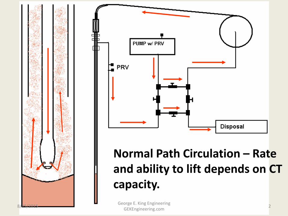
Normal Path Circulation – Rate and ability to lift depends on CT capacity.
8/25/2015 2 George E. King Engineering
GEKEngineering.com
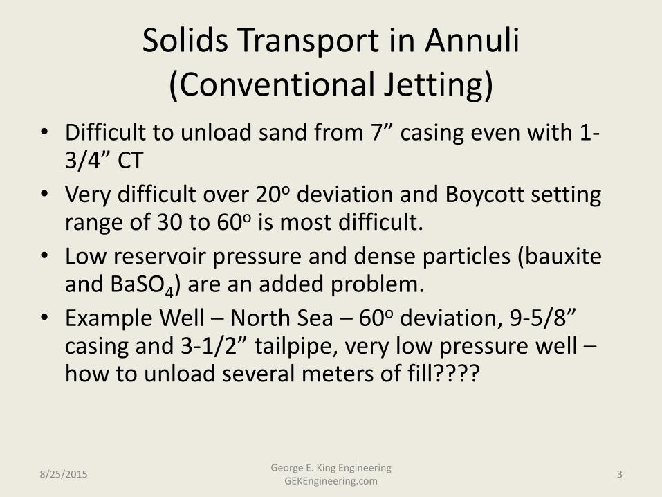
Solids Transport in Annuli (Conventional Jetting)
• Difficult to unload sand from 7” casing even with 1-3/4” CT
• Very difficult over 20o deviation and Boycott setting range of 30 to 60o is most difficult.
• Low reservoir pressure and dense particles (bauxite and BaSO4) are an added problem.
• Example Well – North Sea – 60o deviation, 9-5/8” casing and 3-1/2” tailpipe, very low pressure well – how to unload several meters of fill????
8/25/2015 3 George E. King Engineering
GEKEngineering.com

Reverse Circulating – Above the reservoir with no losses.
1.5 bpm
1.5 bpm
8/25/2015 4 George E. King Engineering
GEKEngineering.com
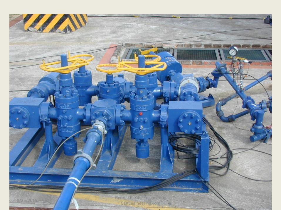
8/25/2015 5 George E. King Engineering
GEKEngineering.com

Reverse Circulating – Above Reservoir (no losses)
Disposal 1.5 bpm
1500 psi 10 psi
1500 psi 2200 psi
PRVs
1.5
bp
m
1.5
bp
m
4800 psi
PRV
1.5 bpm
10 psi
8/25/2015 6 George E. King Engineering
GEKEngineering.com

Reverse Circulating – 2 bpm losses
2.0 bpm
Disposal 1.5 bpm
1500 psi 10 psi
1500 psi 2200 psi
PRVs
1.5
bp
m
3.5
bp
m
4800 psi
PRV
3.5 bpm
10 psi
8/25/2015 7 George E. King Engineering
GEKEngineering.com

Reverse Circulating – 10 bpm losses
10 bpm
Disposal 1.5 bpm
1500 psi 10 psi
1500 psi 2200 psi
PRVs
1.5
bp
m
11
.5 b
pm
4800 psi
PRV
11.5 bpm
10 psi
8/25/2015 8 George E. King Engineering
GEKEngineering.com

Jetting Bridge
Disposal 2.5 bpm
10 psi 10 psi
4000 psi 2200 psi
PRVs
2.5
bp
m
2.5
bp
m
4800 psi
PRV
2.5 bpm
4000 psi
8/25/2015 9 George E. King Engineering
GEKEngineering.com

Baker Oil Tools Reversing/Jetting Nozzle
8/25/2015 10 George E. King Engineering
GEKEngineering.com

Nozzle converts from a single large port for reversing to multiple ports for normal jetting.
Clear string before switch from reverse to normal jetting (prevents erosion of the ports).
8/25/2015 11 George E. King Engineering
GEKEngineering.com
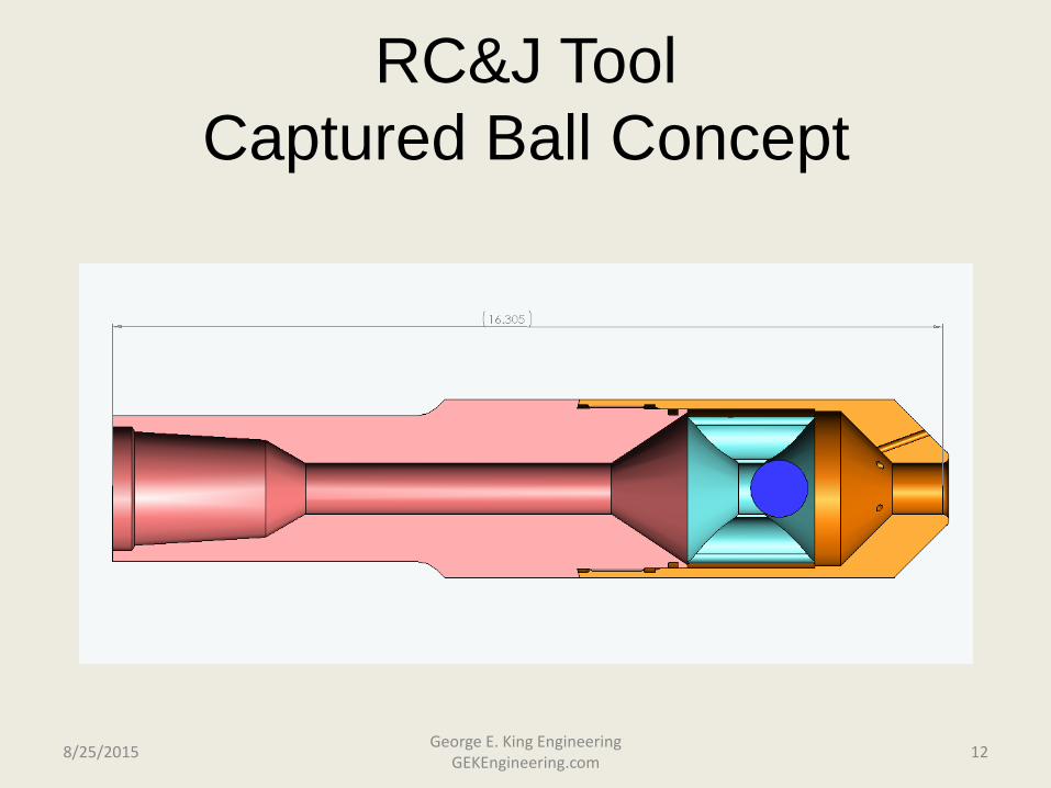
RC&J Tool
Captured Ball Concept
8/25/2015 12 George E. King Engineering
GEKEngineering.com
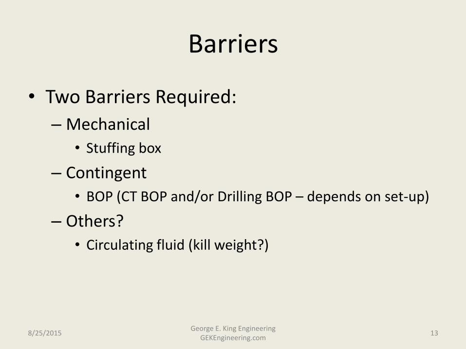
Barriers
• Two Barriers Required:
– Mechanical
• Stuffing box
– Contingent
• BOP (CT BOP and/or Drilling BOP – depends on set-up)
– Others?
• Circulating fluid (kill weight?)
8/25/2015 13 George E. King Engineering
GEKEngineering.com

Risks
• Elimination of the CT flapper valve – small risk, still two barriers
• Sticking the coil – reduced because of higher velocities around solids and clean fluid in the annulus.
• Bridging in the coil – just not seen - minimized by:
– Control rate of bridge entry - control of particles entering the coil
– Control of type of particles that are reversed
– High velocities in the coil
– Fluid with high support at low shear
– Can quickly move from reverse to forward circulation
8/25/2015 14 George E. King Engineering
GEKEngineering.com

Coil Collapse Risks
• Coil far weaker under collapse than burst.
• Precautions and relief considerations needed to keep outside pressure minimized.
• Consider increasing pickup weight on the coil (weight of solids)
• Collapse is function of OD, ID, material strength, ovality, pickup loads (weights and frictions), buoyancy, coil condition, rate of load increase, etc.
• The collapse tables are for round pipe, not oval CT
8/25/2015 15 George E. King Engineering
GEKEngineering.com
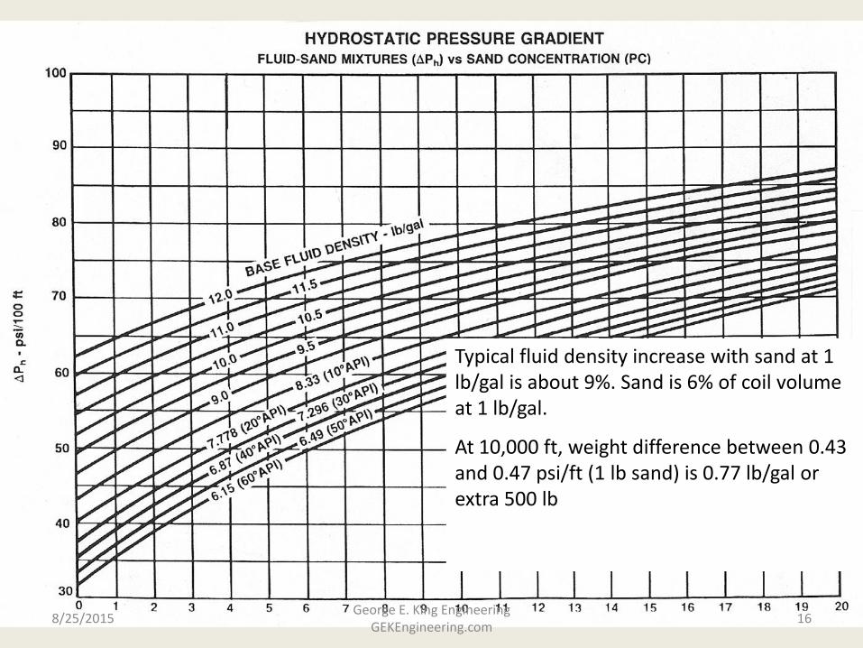
Typical fluid density increase with sand at 1 lb/gal is about 9%. Sand is 6% of coil volume at 1 lb/gal.
At 10,000 ft, weight difference between 0.43 and 0.47 psi/ft (1 lb sand) is 0.77 lb/gal or extra 500 lb
8/25/2015 16 George E. King Engineering
GEKEngineering.com

Higher Risks (Poor Candidates)
• Multi-zone oil wells with cross flow
• Wells not killed by column of water
• Wells that produce but cannot inject
• Deep or bad dog leg wells – where pick-up near the max allowable for the coil.
• HPHT wells – no experience.
8/25/2015 17 George E. King Engineering
GEKEngineering.com

Coil Requirements
• Less than than 40% fatigue wear.
• Less than 4% oval.
• No corrosion, pits, welds or damage.
• Pressure relief valves on backside to prevent coil collapse.
• No more than 10% (volume of coil) solids in the coil at any time.
• Model the job.
8/25/2015 18 George E. King Engineering
GEKEngineering.com

Formation/Well Requirements
• All hydrocarbons push out of pipe (3x pipe volume)
• All zones kept overbalanced.
• Contingency plans for well flow.
• Consider type, shape, density and size of solids lifted.
8/25/2015 19 George E. King Engineering
GEKEngineering.com

Selection of Equipment
• CT – largest possible with > ½” clearance between CT and tubing.
• Large OD nozzle helps prevent bypassing solids in deviated wells.
• Single large hole in nozzle for reversing (hole smaller than minimum anywhere else in the system).
• Where frac sand is only fill, nozzle design is simple.
• No sharp shoulders on tool – oval shape preferred.
• Venturi junk baskets for large pieces.
8/25/2015 20
George E. King Engineering GEKEngineering.com
CT Reverse Circulating Conclusions
1. Must have pressure differentials and hydraulics under control.
2. Frac sand removal is most common target, but other materials are possible with the right equipment.
3. Circulating fluid must have low shear support.
4. Must limit the amount of sand in the coil at any time.
8/25/2015 21 George E. King Engineering
GEKEngineering.com