Embed Size (px)
Citation preview
Research Article s
Volume 6 • Issue 2 • 1000221J Electr Electron Syst, an open access journalISSN: 2332-0796
Open AccessResearch Article
Journal of Electrical & Electronic SystemsJo
urna
l of E
lectrical & Electronic
Systems
ISSN: 2332-0796
Awale et al., J Electr Electron Syst 2017, 6:2DOI: 10.4172/2332-0796.1000221
*Corresponding author: Kapilkumar S Awale, Department of ElectricalEngineering, Shivaji University, Electrical Engineering, India, Tel: 9545835522;E-mail: [email protected]
Received April 11, 2016; Accepted April 24, 2017; Published April 29, 2017
Citation: Awale KS, Kumbhar AU, Kole VA, Kamate JB (2017) Arduino Based MPPT Solar Charge Controller. J Electr Electron Syst 6: 221. doi: 10.4172/2332-0796.1000221
Copyright: © 2017 Awale KS, et al. This is an open-access article distributed under the terms of the Creative Commons Attribution License, which permits unrestricted use, distribution, and reproduction in any medium, provided the original author and source are credited.
Arduino Based MPPT Solar Charge ControllerKapilkumar S Awale*, Amar U Kumbhar, Virashree A Kole and Jayavant B KamateDepartment of Electrical Engineering, Shivaji University, Electrical Engineering, India
Keywords: MPPT (Maximum power point tracking); PV (Solarphotovoltaic); P&O (Perturb and observe); Optocoupler; Arduino; Bluetooth
IntroductionPhotovoltaic electricity generation offers the benefits of: clean,
non-polluting energy generation, production of energy close to the consumer (in case of DPGS), the very little or no maintenance requirement, and of having a very long lifetime. Due to these advantages, today, the photovoltaic is one of the fastest growing markets in the world. However, PV power is still considered to be expensive, and the cost reduction of PV systems is subject to extensive research. From the point of view of power electronics, this goal can be approached by maximizing the energy output of a given PV array. The inverter should ensure the highest possible conversion efficiency, while the requirement for the MPPT control is to operate the PV array at the optimum working point (MPP) in all environmental conditions. A considerable amount of PV capacity today is installed in temperate climate zones. Although modern PV inverters’ MPPT efficiency is very high in stable conditions, further research is needed to achieve similar performance levels in variable conditions. The primary objective of this project is to build efficient solar charger that will recharge the battery properly with minimum loss with overcoming the voltage variation in solar panel. This charge controller will protect the battery from overcharge and deep discharge. It will maximize the solar generation by MPPT method.
The proposed system is to present a novel cost effective and efficient microcontroller based MPPT system for solar photovoltaic system to ensure the maximum power point operation at all changing Environmental condition. The P&O MPPT algorithm is used to control the maximum transfer power from a PV panel. This algorithm is executed by MPPT Controller using LM324 [1-5].
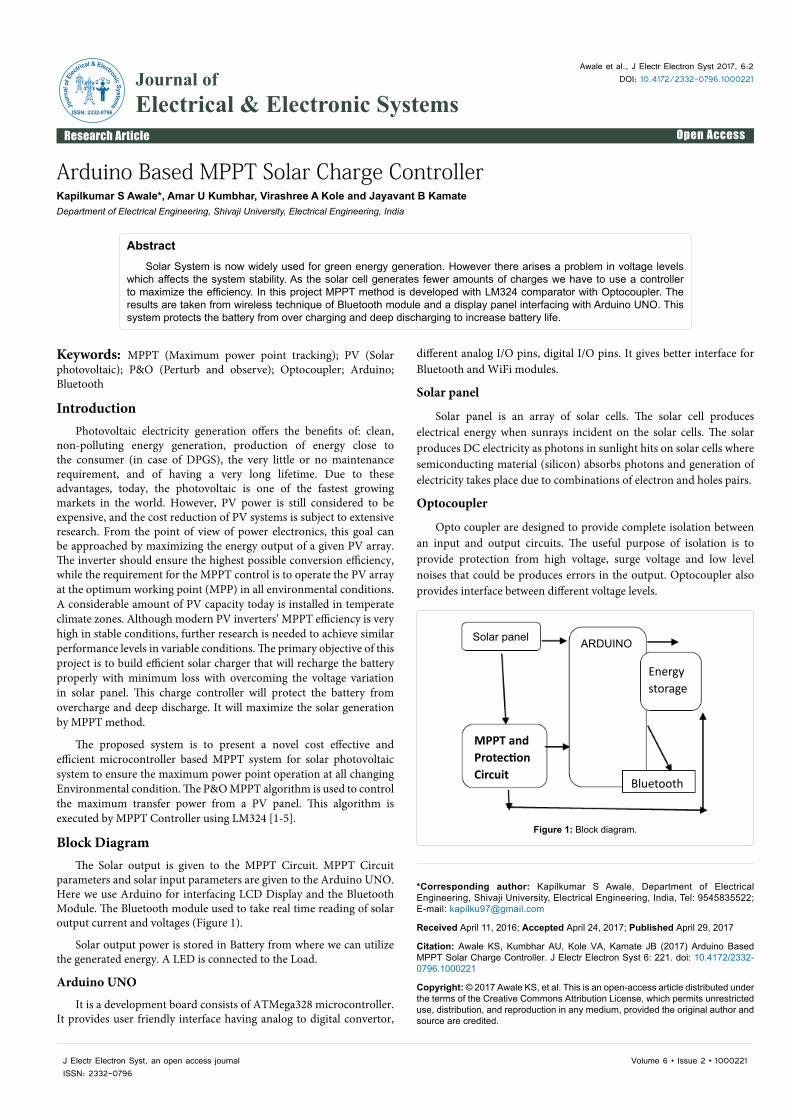
Block Diagram The Solar output is given to the MPPT Circuit. MPPT Circuit
parameters and solar input parameters are given to the Arduino UNO. Here we use Arduino for interfacing LCD Display and the Bluetooth Module. The Bluetooth module used to take real time reading of solar output current and voltages (Figure 1).
Solar output power is stored in Battery from where we can utilize the generated energy. A LED is connected to the Load.
Arduino UNO
It is a development board consists of ATMega328 microcontroller. It provides user friendly interface having analog to digital convertor,
different analog I/O pins, digital I/O pins. It gives better interface for Bluetooth and WiFi modules.
Solar panel
Solar panel is an array of solar cells. The solar cell produces electrical energy when sunrays incident on the solar cells. The solar produces DC electricity as photons in sunlight hits on solar cells where semiconducting material (silicon) absorbs photons and generation of electricity takes place due to combinations of electron and holes pairs.
Optocoupler
Opto coupler are designed to provide complete isolation between an input and output circuits. The useful purpose of isolation is to provide protection from high voltage, surge voltage and low level noises that could be produces errors in the output. Optocoupler also provides interface between different voltage levels.
AbstractSolar System is now widely used for green energy generation. However there arises a problem in voltage levels
which affects the system stability. As the solar cell generates fewer amounts of charges we have to use a controller to maximize the efficiency. In this project MPPT method is developed with LM324 comparator with Optocoupler. The results are taken from wireless technique of Bluetooth module and a display panel interfacing with Arduino UNO. This system protects the battery from over charging and deep discharging to increase battery life.
Solar panel ARDUINO
Energystorage
Bluetooth
MPPT andProtectionCircuit
Figure 1: Block diagram.
Citation: Awale KS, Kumbhar AU, Kole VA, Kamate JB (2017) Arduino Based MPPT Solar Charge Controller. J Electr Electron Syst 6: 221. doi: 10.4172/2332-0796.1000221
Page 2 of 2
Volume 6 • Issue 2 • 1000221J Electr Electron Syst, an open access journalISSN: 2332-0796
IC LM324
LM124 series consists of four independent, high gain, internally frequency compensated operational amplifiers which were designed specifically to operate from a single power supply over a wide range of voltages.
Advantages
• Eliminates need for dual supplies
• Four internally compensated op amps in a single package
• Allows directly sensing near GND and VOUT also goes toGND.
• Power drain suitable for battery operation.
Circuit Diagram The MPPT control circuit is implemented in a MPPT controller
that has IC LM324. The comparator is having 4 op amps used to compare voltage and current. It read the voltage and current of the solar panels through the Optocoupler and calculates the output power. The control circuit compares the PV output voltage and battery voltage and gives required output to the battery. It checks the solar panel output and if the battery voltage is less then it increases the voltage.
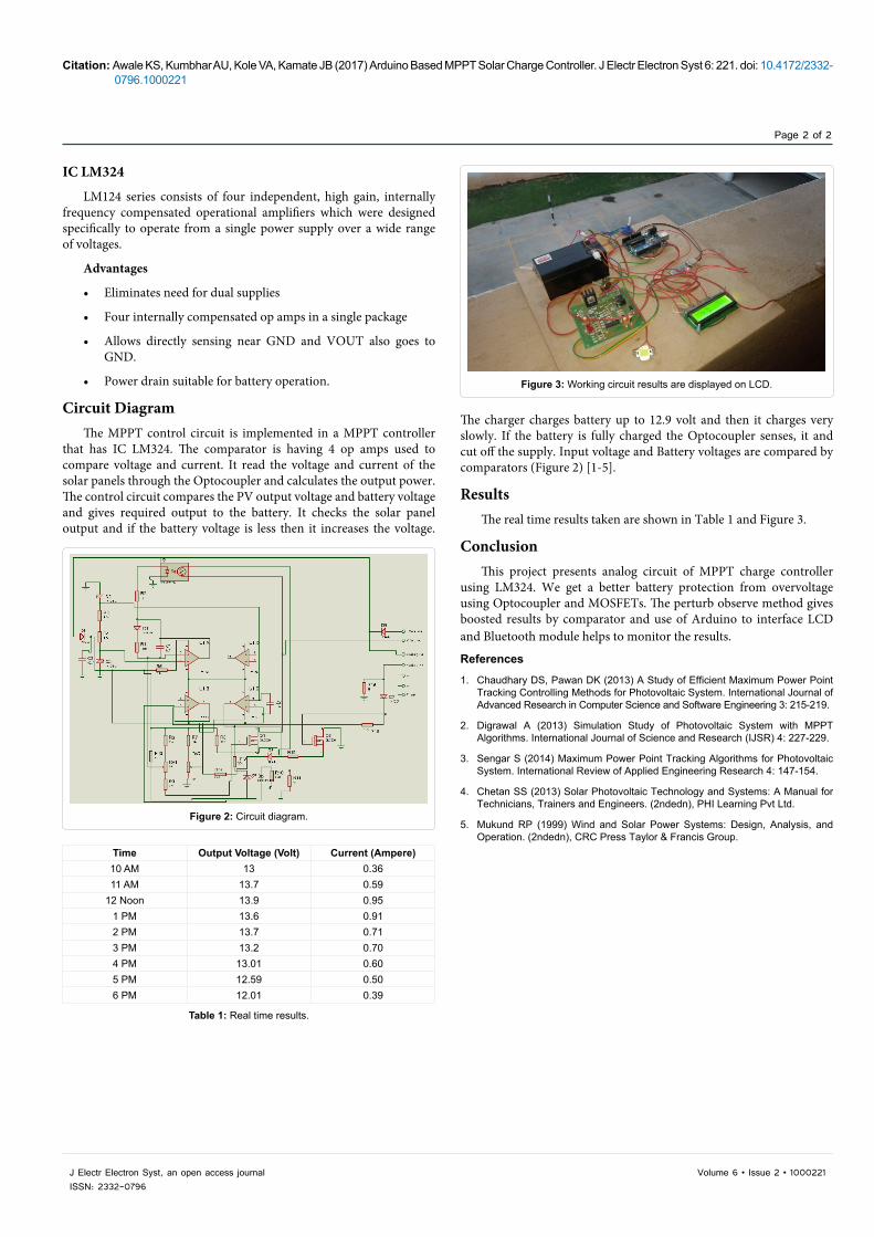
The charger charges battery up to 12.9 volt and then it charges very slowly. If the battery is fully charged the Optocoupler senses, it and cut off the supply. Input voltage and Battery voltages are compared by comparators (Figure 2) [1-5].
ResultsThe real time results taken are shown in Table 1 and Figure 3.
ConclusionThis project presents analog circuit of MPPT charge controller
using LM324. We get a better battery protection from overvoltage using Optocoupler and MOSFETs. The perturb observe method gives boosted results by comparator and use of Arduino to interface LCD and Bluetooth module helps to monitor the results.
References
1. Chaudhary DS, Pawan DK (2013) A Study of Efficient Maximum Power Point Tracking Controlling Methods for Photovoltaic System. International Journal ofAdvanced Research in Computer Science and Software Engineering 3: 215-219.
2. Digrawal A (2013) Simulation Study of Photovoltaic System with MPPTAlgorithms. International Journal of Science and Research (IJSR) 4: 227-229.
3. Sengar S (2014) Maximum Power Point Tracking Algorithms for PhotovoltaicSystem. International Review of Applied Engineering Research 4: 147-154.
4. Chetan SS (2013) Solar Photovoltaic Technology and Systems: A Manual forTechnicians, Trainers and Engineers. (2ndedn), PHI Learning Pvt Ltd.
5. Mukund RP (1999) Wind and Solar Power Systems: Design, Analysis, andOperation. (2ndedn), CRC Press Taylor & Francis Group.
Figure 2: Circuit diagram.
Figure 3: Working circuit results are displayed on LCD.
Time Output Voltage (Volt) Current (Ampere)10 AM 13 0.3611 AM 13.7 0.59
12 Noon 13.9 0.951 PM 13.6 0.912 PM 13.7 0.713 PM 13.2 0.704 PM 13.01 0.605 PM 12.59 0.506 PM 12.01 0.39
Table 1: Real time results.


![HM apps built for DM's (2) - stewartsshops.com · *6 1(1< %urzqlh 7urrs ... &kd]\ &hqwudo 5xudo 6fkrro 2shq 6zlp 3urjudp &kd] ... &dwkrolf &kdulwlhv &rpp 6yfv 'xwfkhvv &rxqw\](https://img.pdfslide.us/doc/110x75/5c86b3e009d3f2206a8c119d/hm-apps-built-for-dms-2-6-11-urzqlh-7urrs-kd-hqwudo-5xudo-6fkrro.jpg)


![VWHP - European Commission(8523($1 &200,66,21 3URJUHVV RQ 2SHQ 6FLHQFH 7RZDUGV D 6KDUHG 5HVHDUFK .QRZOHGJH 6\VWHP )LQDO 5HSRUW RI WKH 2SHQ 6FLHQFH 3ROLF\ 3ODWIRUP (YD 0HQGH] &KDLU](https://img.pdfslide.us/doc/110x75/604a2739444e2b15f228a002/vwhp-european-commission-85231-2006621-3urjuhvv-rq-2shq-6flhqfh-7rzdugv.jpg)