Embed Size (px)
Citation preview
CT PhysicsCT Physics
V.G.Wimalasena
Principal
School of radiography
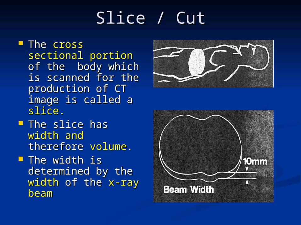
Slice / CutSlice / Cut The The cross sectionalcross sectional
portion portion of the body of the body which is scanned for which is scanned for the production of the production of CT image is called a CT image is called a slice.slice.
The slice has The slice has width width andand therefore therefore volumevolume..
The width is The width is determined by the determined by the width width of the of the x-ray x-ray beambeam
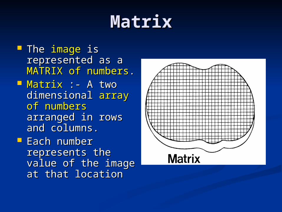
MatrixMatrix The The imageimage is is
represented as a represented as a MATRIX of numbersMATRIX of numbers..
MatrixMatrix :- A two :- A two dimensional dimensional array ofarray of numbersnumbers arranged in arranged in rows and columns.rows and columns.
Each number Each number represents the value represents the value of the image at that of the image at that locationlocation
VOXELVOXEL
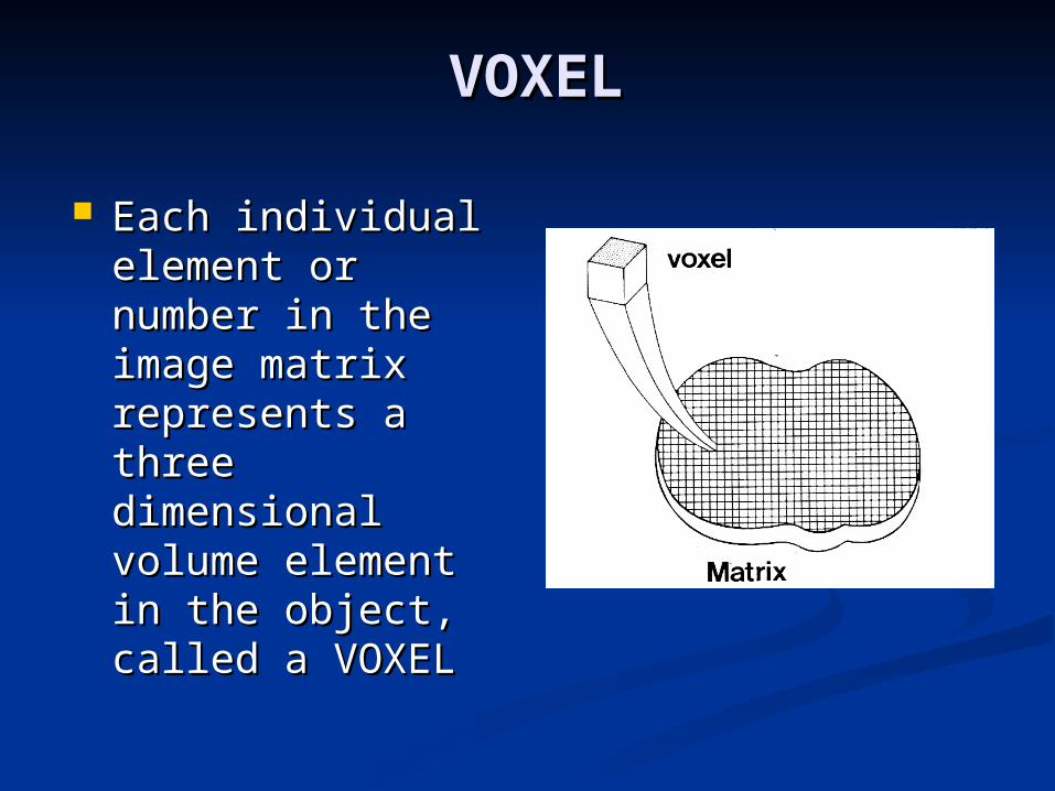
Each individual Each individual element or number element or number in the image in the image matrix represents matrix represents a three a three dimensional dimensional volume element in volume element in the object, called a the object, called a VOXELVOXEL
PIXELPIXEL
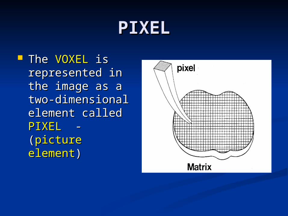
The The VOXELVOXEL is is represented in the represented in the image as a two-image as a two-dimensional dimensional element called element called PIXELPIXEL - ( - (picture picture elementelement))
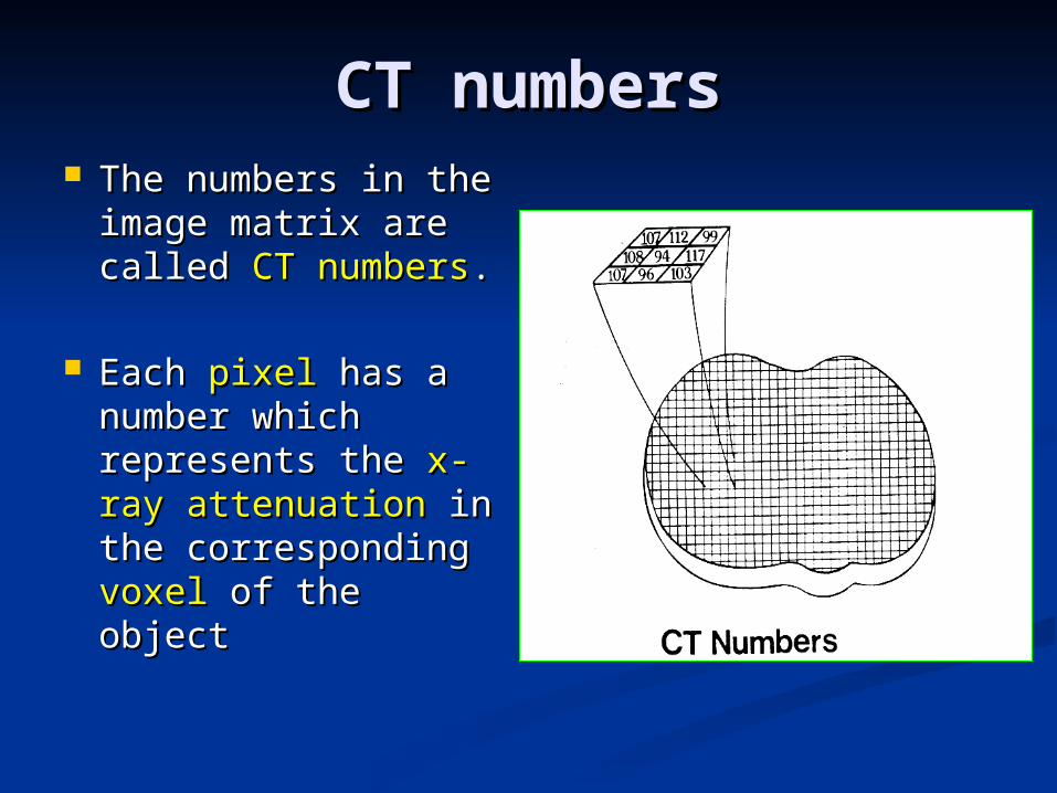
CT numbersCT numbers The numbers in The numbers in
the image matrix the image matrix are called are called CT CT numbersnumbers. .
Each Each pixelpixel has a has a number which number which represents the represents the x-x-rayray attenuationattenuation in in the corresponding the corresponding voxelvoxel of the object of the object
Visual image & Gray Visual image & Gray ScaleScale
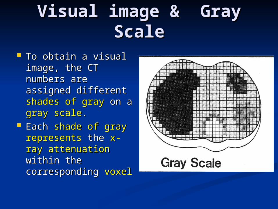
To obtain a visual To obtain a visual image, the CT image, the CT numbers are numbers are assigned different assigned different shades of grayshades of gray on a on a gray scalegray scale..
Each Each shade of grayshade of gray representsrepresents the the x-ray x-ray attenuationattenuation within within the corresponding the corresponding voxelvoxel
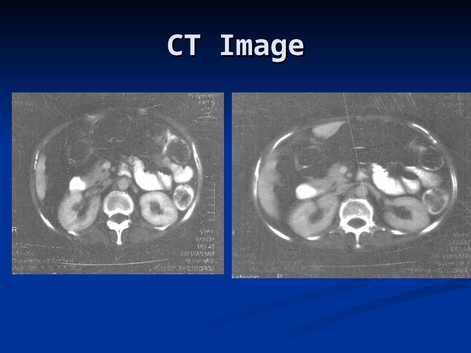
CT ImageCT Image
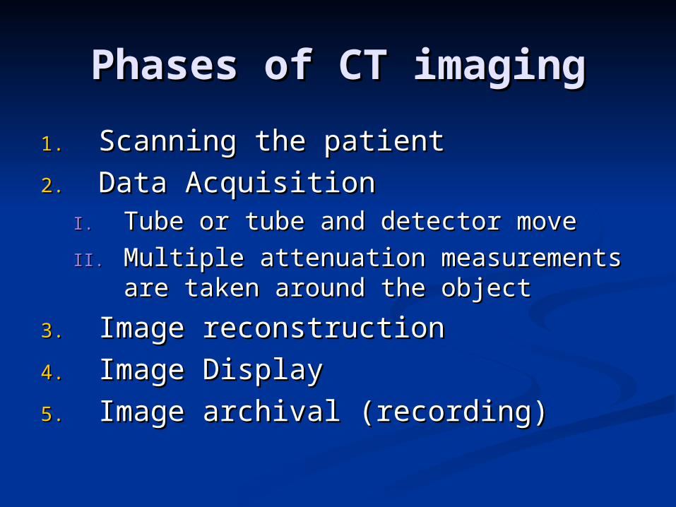
Phases of CT imagingPhases of CT imaging
1.1. Scanning the patientScanning the patient
2.2. Data AcquisitionData AcquisitionI.I. Tube or tube and detector moveTube or tube and detector move
II.II. Multiple attenuation measurements Multiple attenuation measurements are taken around the objectare taken around the object
3.3. Image reconstructionImage reconstruction
4.4. Image DisplayImage Display
5.5. Image archival (recording)Image archival (recording)
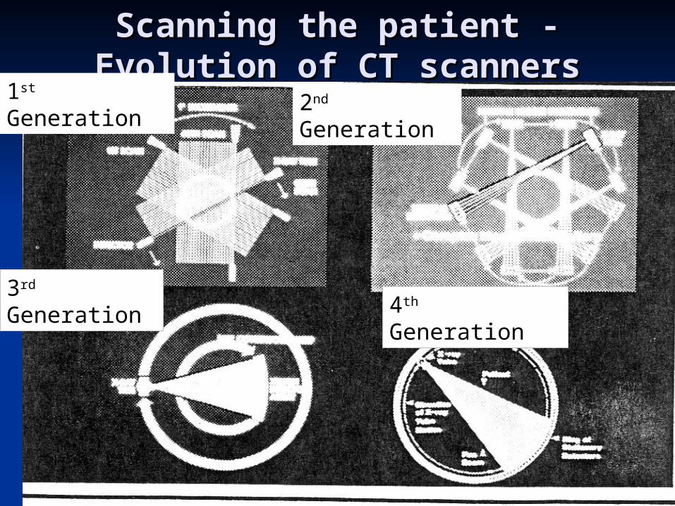
Scanning the patient - Scanning the patient - Evolution of CT scannersEvolution of CT scanners
1st Generation 2nd Generation
3rd Generation4th Generation
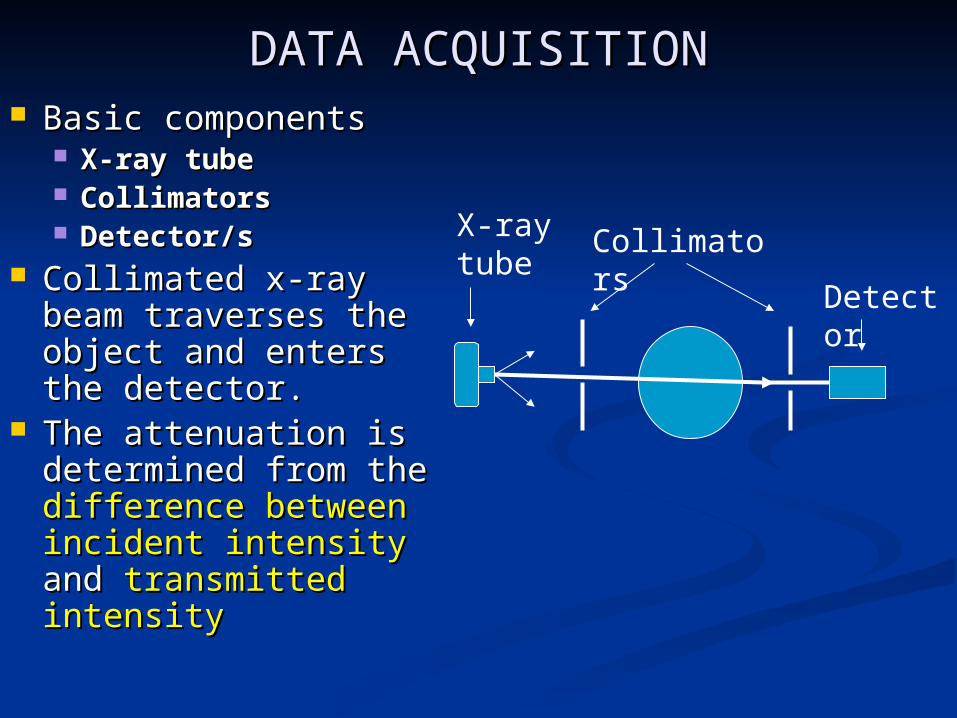
DATA ACQUISITIONDATA ACQUISITION Basic componentsBasic components
X-ray tubeX-ray tube CollimatorsCollimators Detector/sDetector/s
Collimated x-ray Collimated x-ray beam traverses the beam traverses the object and enters object and enters the detector.the detector.
The attenuation is The attenuation is determined from the determined from the difference betweendifference between incident intensityincident intensity and and transmitted transmitted intensityintensity
X-ray tube
Collimators
Detector
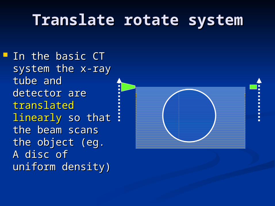
Translate rotate systemTranslate rotate system
In the basic CT In the basic CT system the x-ray system the x-ray tube and detector tube and detector are are translated translated linearlylinearly so that so that the beam scans the beam scans the object (eg. A the object (eg. A disc of uniform disc of uniform density)density)
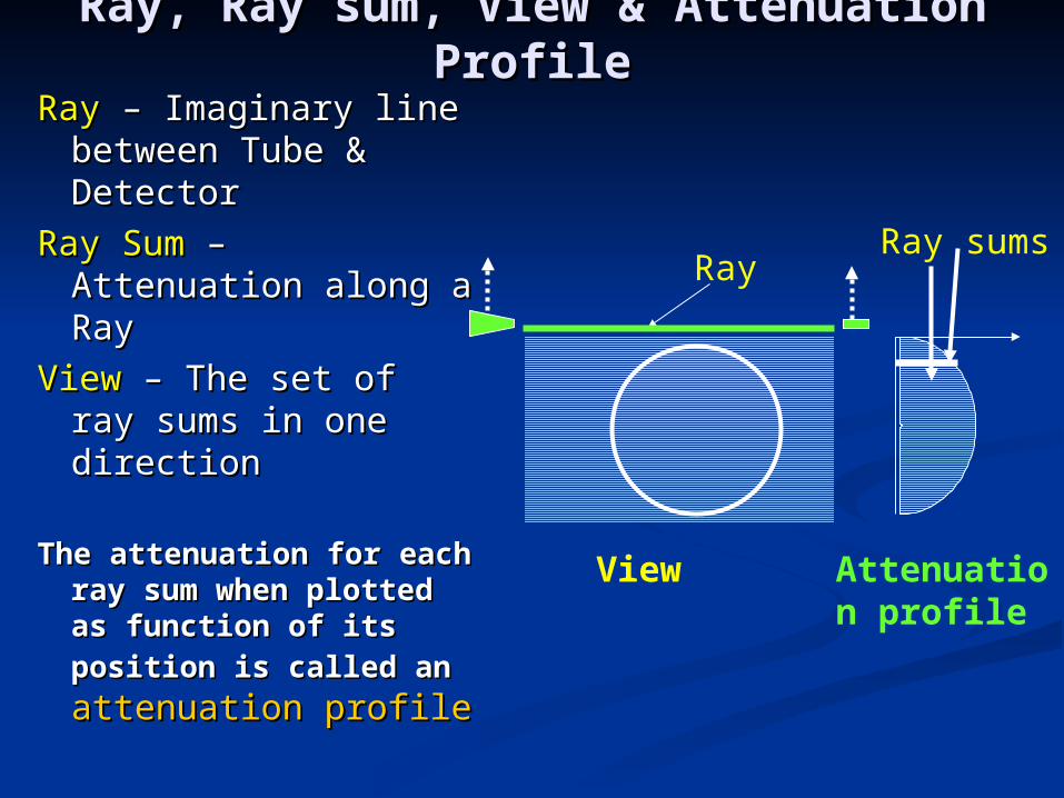
Ray, Ray sum, View & Attenuation Ray, Ray sum, View & Attenuation ProfileProfile
RayRay – Imaginary line – Imaginary line between Tube & between Tube & DetectorDetector
Ray SumRay Sum – Attenuation – Attenuation along a Rayalong a Ray
View View – The set of ray – The set of ray sums in one sums in one directiondirection
The attenuation for The attenuation for each ray sum when each ray sum when plotted as function of plotted as function of its position is called its position is called anan attenuation attenuation profileprofile
View Attenuation profile
RayRay sums
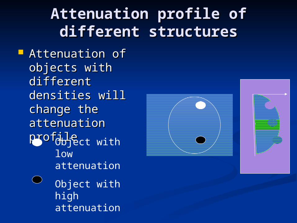
Attenuation profile of different Attenuation profile of different structuresstructures
Attenuation of Attenuation of objects with objects with different densities different densities will change the will change the attenuation profileattenuation profile
Object with low attenuation
Object with high attenuation
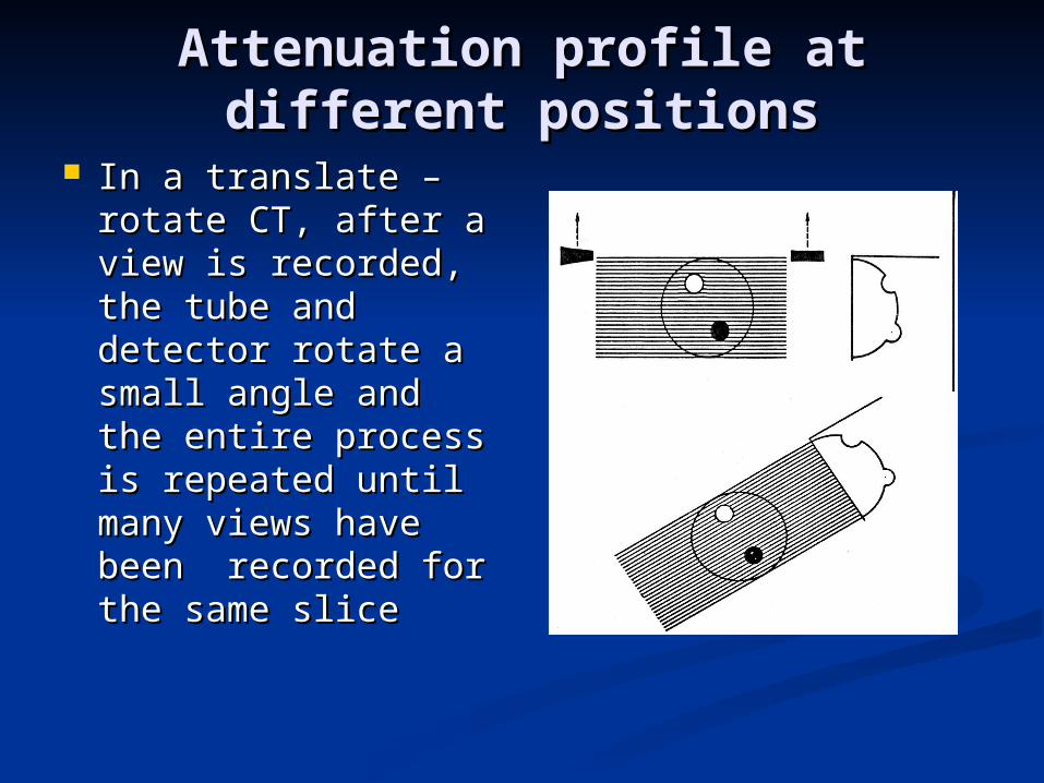
Attenuation profile at different Attenuation profile at different positionspositions
In a translate –In a translate –rotate CT, after a rotate CT, after a view is recorded, view is recorded, the tube and the tube and detector rotate a detector rotate a small angle and small angle and the entire process the entire process is repeated until is repeated until many views have many views have been recorded for been recorded for the same slicethe same slice
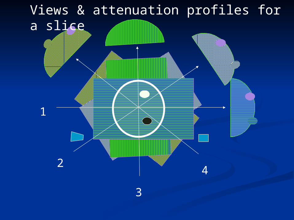
Views & attenuation profiles for a slice
1
2
3
4
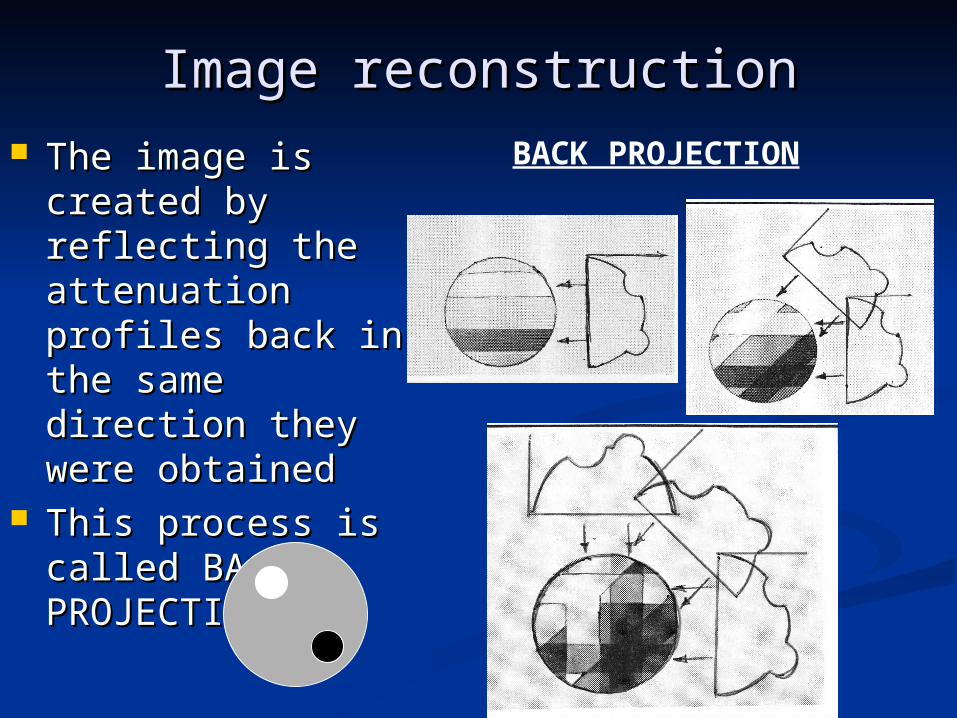
Image reconstructionImage reconstruction The image is The image is
created by created by reflecting the reflecting the attenuation profiles attenuation profiles back in the same back in the same direction they were direction they were obtainedobtained
This process is This process is called BACK called BACK PROJECTIONPROJECTION
BACK PROJECTION
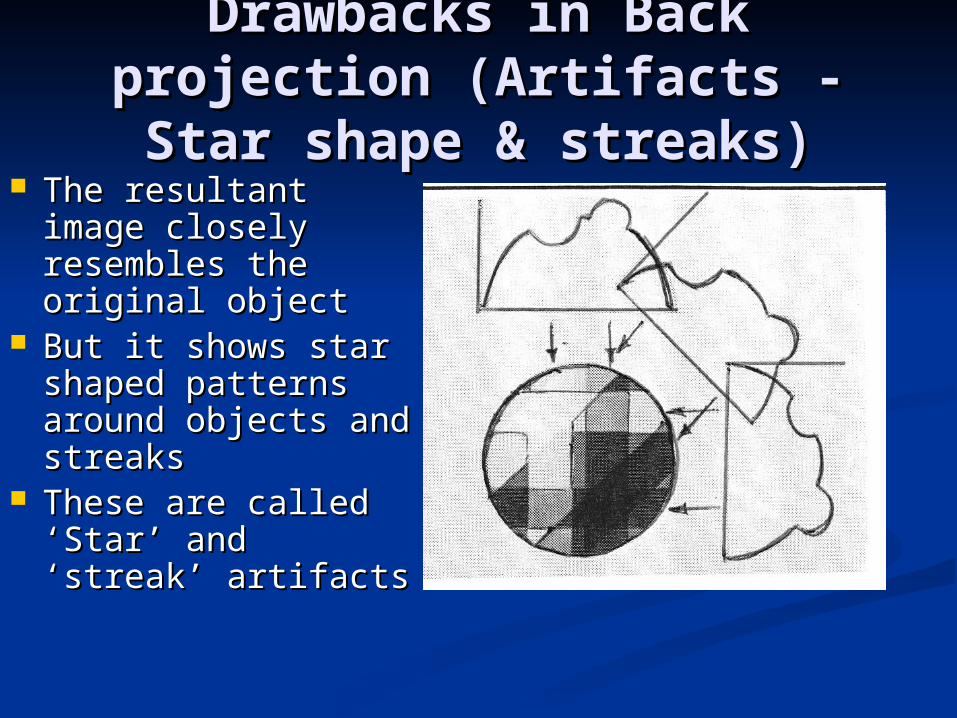
Drawbacks in Back Drawbacks in Back projection (Artifacts - Star projection (Artifacts - Star
shape & streaks)shape & streaks) The resultant The resultant
image closely image closely resembles the resembles the original objectoriginal object
But it shows star But it shows star shaped patterns shaped patterns around objects and around objects and streaks streaks
These are called These are called ‘Star’ and ‘streak’ ‘Star’ and ‘streak’ artifactsartifacts
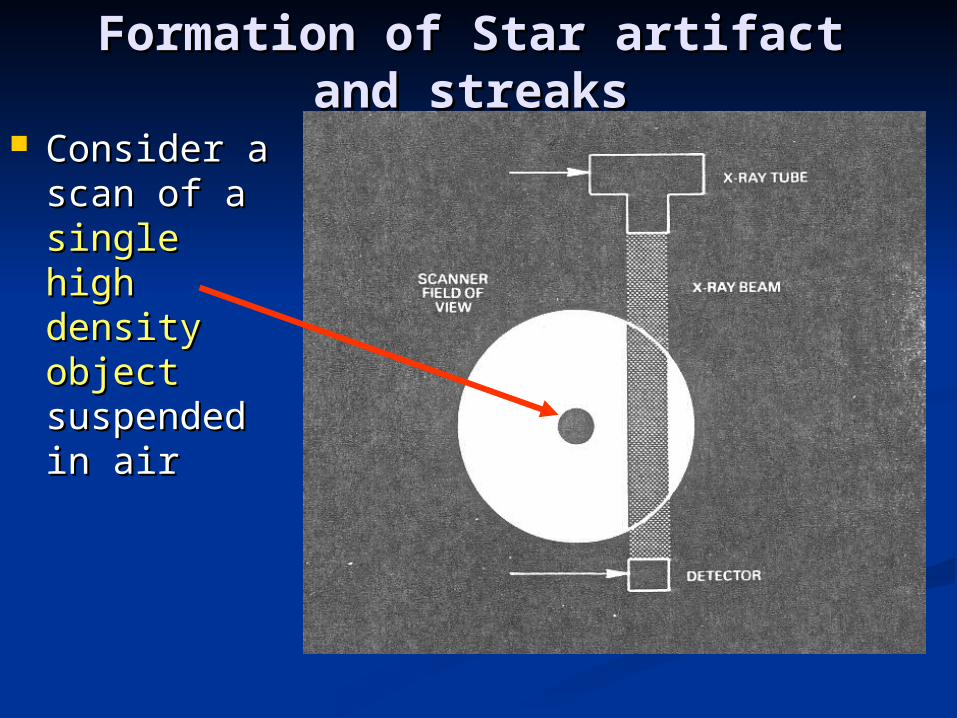
Formation of Star artifact and Formation of Star artifact and streaksstreaks
Consider a Consider a scan of a scan of a single high single high density density objectobject suspended suspended in airin air
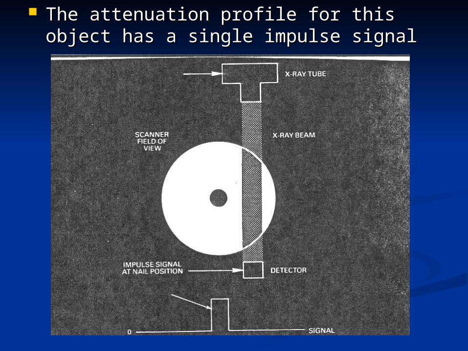
The attenuation profile for this object has The attenuation profile for this object has a single impulse signala single impulse signal
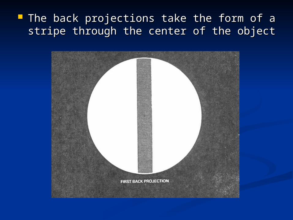
The back projections take the form of a The back projections take the form of a stripe through the center of the objectstripe through the center of the object
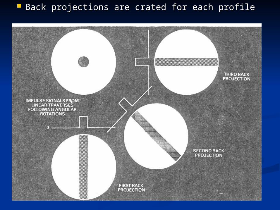
Back projections are crated for each profileBack projections are crated for each profile
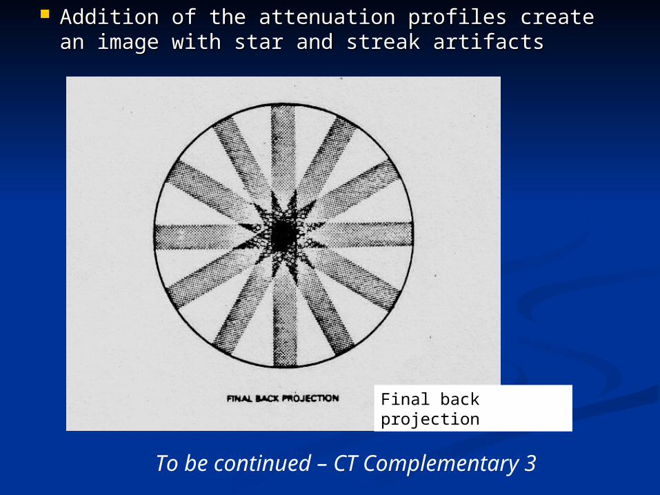
Addition of the attenuation profiles create Addition of the attenuation profiles create an image with star and streak artifactsan image with star and streak artifacts
Final back projection
To be continued – CT Complementary 3