Embed Size (px)
Citation preview


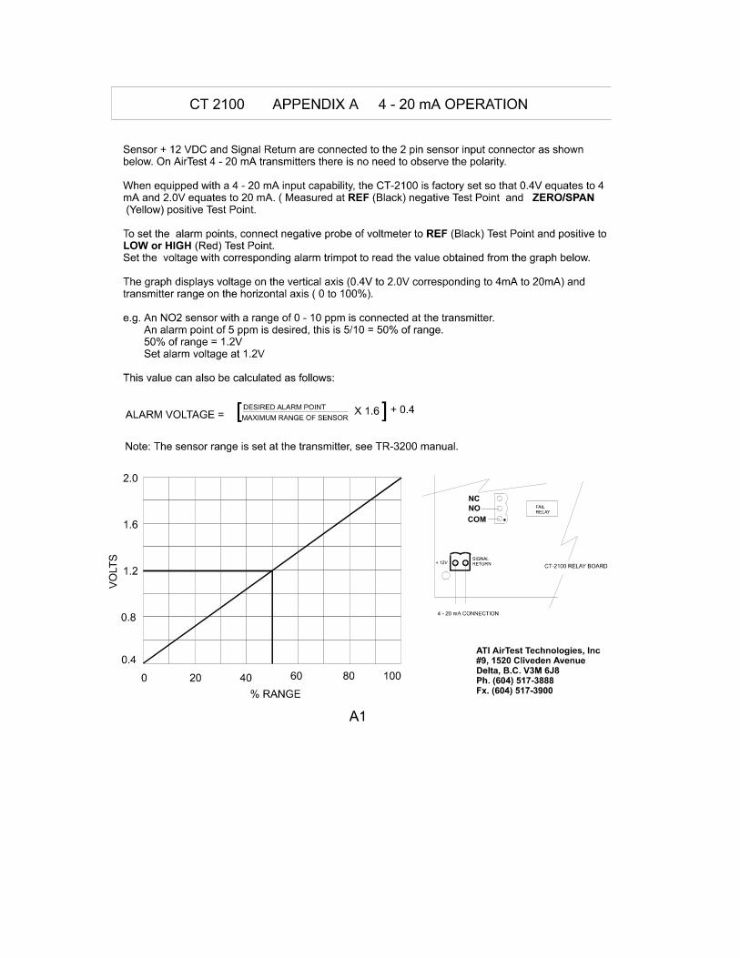
CT 2100 VEHICLE EXHAUST DETECTOR
INTRODUCTION: The CT 2100 is a dual sensor, carbon monoxide and propane/natural gas vehicle exhaust detector. It is a wall-mounted, stand-alone, self-contained gas detection system designed to rugged, commercial installation specifications that require continuous 24 hour a day monitoring. It is typically used in areas such as enclosed or underground parking structures, loading docks, equipment rooms or arenas where gasoline engine exhaust could pose a health problem. The detector is produced in single sensor (CT 1100) or dual sensor (CT 2100) configurations. In addition to the normal vehicle exhaust sensors, the CT 2100 can be supplied with ammonia or other refrigerant gas sensors to satisfy a variety of monitoring applications. It is backed by a two year warranty.
Sensors can be the same gas or different gases. Rotary switch on the circuit board selects the
desired delay. Low and high alarm points can be set anywhere within the
instrument range. Independent, low turns off before high turns on and
dependent, low remains on when high turns on. SPDT 10 amp.
On/off switch provided. To simulate alarm conditions for testing installations, the test sequence is
initiated with a momentary contact switch. The unit automatically returns to normal operating mode after the test is completed.
This results in more accurate measurements .If conditions exist such as sensor connection being severed, sensor
burn- out, circuit board failure, etc. the “fail” LED illuminates, the audible alarm is activated and the fail relay energizes the exhaust fans which will run until the fail condition is rectified. If a total power failure to the CT 2100 is experienced, the fail relay will still activate the exhaust fans.
The system is self-contained in a small wall mount enclosure. LED’s illuminate to indicate Power On, Fail State, Low and High
Alarm State.Pre-drilled holes and plugs provided for easy installation.
FEATURES OF THE CT 2100 SYSTEM:
Dual sensor system - User selectable time delayon relay activation -
User settable alarm points -
User configurable alarm operation -
5 heavy duty relays provided - Audible alarm - System test switch -
Temperature compensationat the sensor - Fail-safe system design -
Compact - Status displayon front panel -
Choice of Rear or top entry -
!!
!
!!!!!
!!
!!
!
ATI AirTest Technologies, Inc#9, 1520 Cliveden AvenueDelta, B.C. V3M 6J8Ph. (604) 517-3888Fx. (604) 517-3900
1
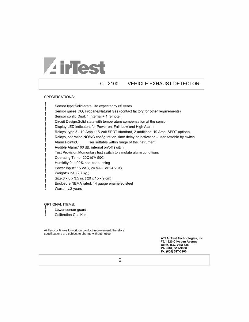
SPECIFICATIONS:
Sensor type:Solid-state, life expectancy >5 years
Sensor gases:CO, Propane/Natural Gas (contact factory for other requirements)
Sensor config:Dual, 1 internal + 1 remote .
Circuit Design:Solid state with temperature compensation at the sensor
Display:LED indicators for Power on, Fail, Low and High Alarm
Relays, type:3 - 10 Amp.115 Volt SPDT standard, 2 additional 10 Amp. SPDT optional
Relays, operation:NO/NC configuration, time delay on activation - user settable by switch
Alarm Points:U ser settable within range of the instrument.
Audible Alarm:100 dB, internal on/off switch
Test Provision:Momentary test switch to simulate alarm conditions
Operating Temp:-20C to + 50C
Humidity:0 to 90% non-condensing
Power Input:115 VAC, 24 VAC or 24 VDC
Weight:6 lbs. (2.7 kg.)
Size:8 x 6 x 3.5 in. ( 20 x 15 x 9 cm)
Enclosure:NEMA rated, 14 gauge enameled steel
Warranty:2 years
OPTIONAL ITEMS:
Lower sensor guard
Calibration Gas Kits
!!!!!!!!!!!!!!!!!
!!
°°
AirTest continues to work on product improvement, therefore, specifications are subject to change without notice.
ATI AirTest Technologies, Inc#9, 1520 Cliveden AvenueDelta, B.C. V3M 6J8Ph. (604) 517-3888Fx. (604) 517-3900
CT 2100 VEHICLE EXHAUST DETECTOR
2
CT 2100 VEHICLE EXHAUST DETECTOR
ATI AirTest Technologies, Inc#9, 1520 Cliveden AvenueDelta, B.C. V3M 6J8Ph. (604) 517-3888Fx. (604) 517-3900
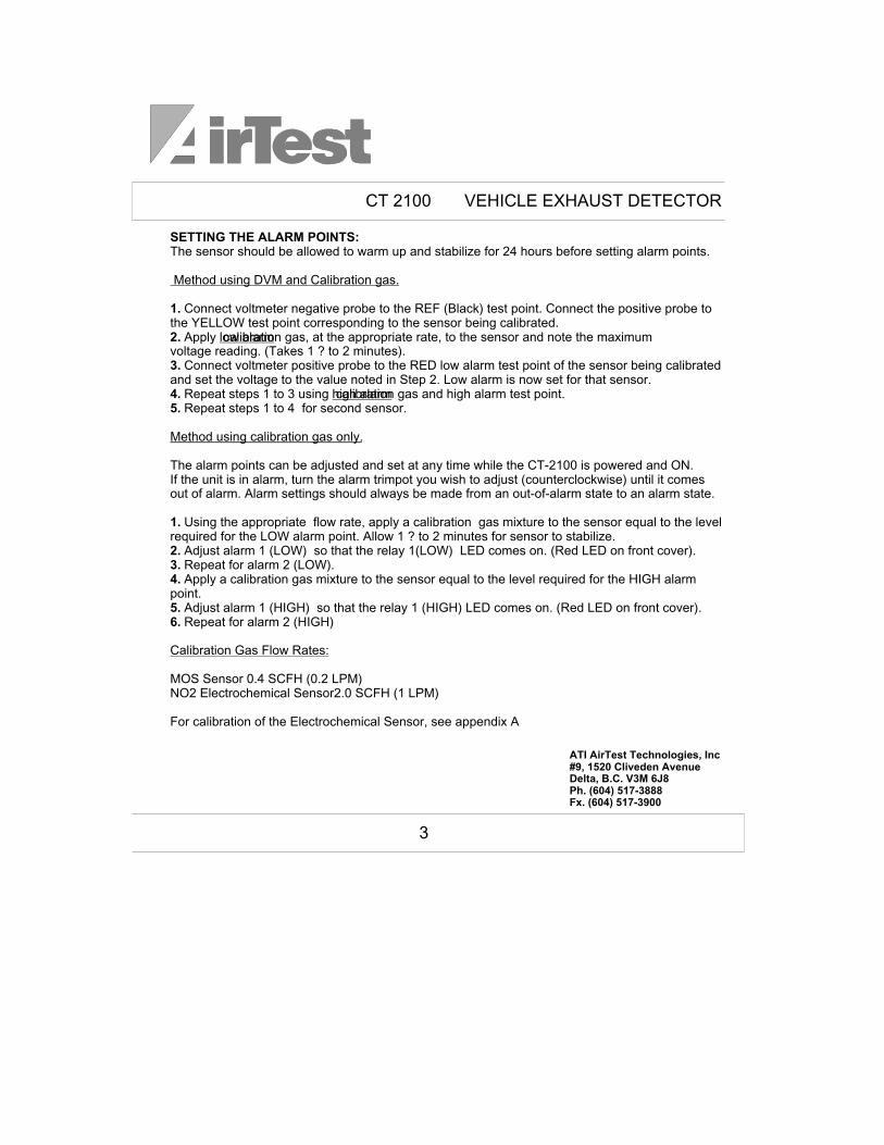
SETTING THE ALARM POINTS:
1.
2.3.4.
5.6.
The sensor should be allowed to warm up and stabilize for 24 hours before setting alarm points.
Connect voltmeter negative probe to the REF (Black) test point. Connect the positive probe to the YELLOW test point corresponding to the sensor being calibrated.
Apply calibration gas, at the appropriate rate, to the sensor and note the maximum voltage reading. (Takes 1 ? to 2 minutes).
Connect voltmeter positive probe to the RED low alarm test point of the sensor being calibrated and set the voltage to the value noted in Step 2. Low alarm is now set for that sensor.
Repeat steps 1 to 3 using calibration gas and high alarm test point. Repeat steps 1 to 4 for second sensor.
The alarm points can be adjusted and set at any time while the CT-2100 is powered and ON.
MOS Sensor 0.4 SCFH (0.2 LPM)NO2 Electrochemical Sensor2.0 SCFH (1 LPM)
For calibration of the Electrochemical Sensor, see appendix A
Method using DVM and Calibration gas.
low alarm
high alarm
Method using calibration gas only.
Calibration Gas Flow Rates:
1.
2.
3.
4.5.
If the unit is in alarm, turn the alarm trimpot you wish to adjust (counterclockwise) until it comes out of alarm. Alarm settings should always be made from an out-of-alarm state to an alarm state.
Using the appropriate flow rate, apply a calibration gas mixture to the sensor equal to the level required for the LOW alarm point. Allow 1 ? to 2 minutes for sensor to stabilize.
Adjust alarm 1 (LOW) so that the relay 1(LOW) LED comes on. (Red LED on front cover). Repeat for alarm 2 (LOW). Apply a calibration gas mixture to the sensor equal to the level required for the HIGH alarm
point. Adjust alarm 1 (HIGH) so that the relay 1 (HIGH) LED comes on. (Red LED on front cover). Repeat for alarm 2 (HIGH)
3
TRANSFORMER
POWER SWITCH
+ / L
N
GND
115VAC IN or24VAC IN
COM
NC
NOLOW RELAY
LOW RELAY
HIGH RELAY
HIGH RELAY
FAILRELAY
G B W R
GREENBLACK
WHITE
Use 18 ga. min. wire
TO EQUIPMENTENERGIZED ON FAIL
TO EQUIPMENTENERGIZED ONLOW ALARM
TO EQUIPMENTENERGIZED ONHIGH ALARM
MOS SENSOR
MOS SENSOR
RED
ATI AirTest Technologies, Inc
CT 2100 System Wiring - MOS Sensors
CT2100-004
dcmPage 1 of 1 March 24, 1999
0
Drawing number
Drawn by Rev
. RELAYS RATED AT MAXIMUM 10 AMPS
SENSOR 1 SENSOR 2
PLUG-IN CONNECTORS
5
SENSOR 1
SENSOR 2
COM
NCNO
COM
NCNO
COMNC
NO
COM
NONC
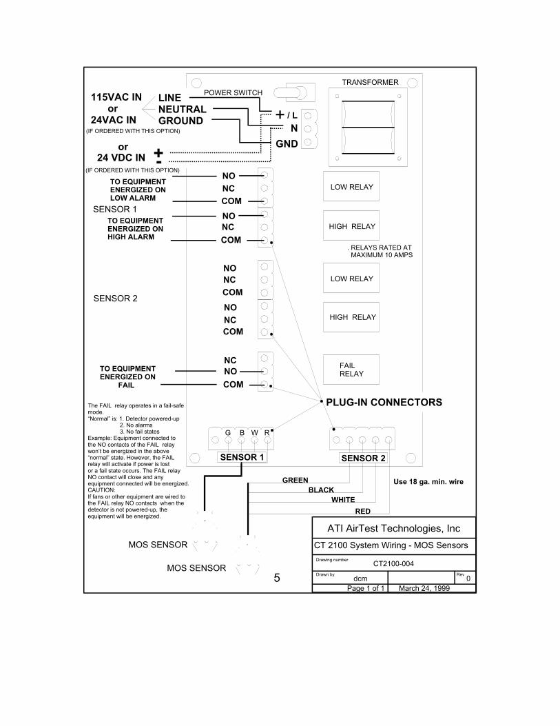
The FAIL relay operates in a fail-safemode.“Normal” is: 1. Detector powered-up 2. No alarms 3. No fail statesExample: Equipment connected tothe NO contacts of the FAIL relay won’t be energized in the above “normal” state. However, the FAIL relay will activate if power is lost or a fail state occurs. The FAIL relayNO contact will close and any equipment connected will be energized.CAUTION:If fans or other equipment are wired tothe FAIL relay NO contacts when the detector is not powered-up, the equipment will be energized.
GROUND
LINENEUTRAL
24 VDC IN +-or
(IF ORDERED WITH THIS OPTION)
(IF ORDERED WITH THIS OPTION)

TRANSFORMER
POWER SWITCH
+ / L
N
GND
115VAC IN or24VAC IN
COM
NC
NOLOW RELAY
LOW RELAY
HIGH RELAY
HIGH RELAY
FAILRELAY
G B W R
GREENBLACK
WHITE
Use 18 ga. min. wire
TO EQUIPMENTENERGIZED ON FAIL
TO EQUIPMENTENERGIZED ONLOW ALARM
TO EQUIPMENTENERGIZED ONHIGH ALARM
MOS SENSOR
MOS SENSOR
RED
ATI AirTest Technologies, Inc
CT 2100 System Wiring - MOS Sensors
CT2100-004
dcmPage 1 of 1 March 24, 1999
0
Drawing number
Drawn by Rev
. RELAYS RATED AT MAXIMUM 10 AMPS
SENSOR 1 SENSOR 2
PLUG-IN CONNECTORS
5
SENSOR 1
SENSOR 2
COM
NCNO
COM
NCNO
COMNC
NO
COM
NONC
The FAIL relay operates in a fail-safemode.“Normal” is: 1. Detector powered-up 2. No alarms 3. No fail statesExample: Equipment connected tothe NO contacts of the FAIL relay won’t be energized in the above “normal” state. However, the FAIL relay will activate if power is lost or a fail state occurs. The FAIL relayNO contact will close and any equipment connected will be energized.CAUTION:If fans or other equipment are wired tothe FAIL relay NO contacts when the detector is not powered-up, the equipment will be energized.
GROUND
LINENEUTRAL
24 VDC IN +-or
(IF ORDERED WITH THIS OPTION)
(IF ORDERED WITH THIS OPTION)