Embed Size (px)
Citation preview

UNCLASSIFIED
UNCLASSIFIED
CSMAC Working Group 5
Sub-Working Group 4 Report
Feasibility of DoD PGM and Miscellaneous Airborne
Systems Sharing the 1755-1850 MHz Band with
Commercial Long Term Evolution Systems
19 June 2013
DISTRIBUTION STATEMENT A.

UNCLASSIFIED
i
UNCLASSIFIED
TABLE OF CONTENTS
1 INTRODUCTION.......................................................................................................... 1-1
1.1 BACKGROUND ............................................................................................................ 1-1
1.2 EXECUTIVE SUMMARY OF FINDINGS ................................................................ 1-1
1.2.1 Analyses ....................................................................................................................... 1-1
1.2.2 Results .......................................................................................................................... 1-2
1.2.3 Conclusion ................................................................................................................... 1-2
1.3 SUMMARY OF RECOMMENDATIONS .................................................................. 1-3
1.3.1 PGM ............................................................................................................................. 1-3
1.3.2 TactiLink Eagle ............................................................................................................ 1-3
1.3.3 JTRS AMF ................................................................................................................... 1-4
1.3.4 TTNT ........................................................................................................................... 1-4
1.3.5 CMDL .......................................................................................................................... 1-5
1.3.6 Dragoon........................................................................................................................ 1-5
1.3.7 VORTEX ..................................................................................................................... 1-6
1.3.8 ROVER ........................................................................................................................ 1-6
1.4 PATH FORWARD ........................................................................................................ 1-6
1.4.1 Promising Opportunities for Future Studies ................................................................ 1-6
2 SUB-WORKING GROUP 4 DETAILS ....................................................................... 2-1
2.1 ORGANIZATION ......................................................................................................... 2-1
2.2 PARTICIPATION ......................................................................................................... 2-1
2.3 WORK PLAN................................................................................................................. 2-1
2.4 FUNCTIONING ............................................................................................................. 2-1
2.5 ABSTRACT .................................................................................................................... 2-1
2.5.1 UE Transmitters to DoD Receiver ............................................................................... 2-2
2.5.2 DoD Transmitter to LTE Base Station Receiver ......................................................... 2-3
3 WORK PLANS .............................................................................................................. 3-1
3.1 PGMs ............................................................................................................................... 3-1

UNCLASSIFIED
ii
UNCLASSIFIED
3.2 TactiLink Eagle .............................................................................................................. 3-1
3.3 JTRS AMF ...................................................................................................................... 3-1
3.4 TTNT ............................................................................................................................... 3-1
3.5 LITENING/Sniper Pods with CMDL .......................................................................... 3-1
3.6 Dragoon ........................................................................................................................... 3-1
3.7 VORTEX ........................................................................................................................ 3-1
3.8 ROVER ........................................................................................................................... 3-1
4 DETAILED APPROACHES AND FINDINGS .......................................................... 4-1
4.1 PGMS .............................................................................................................................. 4-1
4.1.1 EMI Analysis ............................................................................................................... 4-1
4.1.1.1 Analysis Parameters ............................................................................................. 4-1
4.1.1.2 Results .................................................................................................................. 4-1
4.1.1.3 Summary .............................................................................................................. 4-5
4.1.1.4 Recommendations ................................................................................................ 4-6
4.2 TACTILINK EAGLE .................................................................................................... 4-7
4.2.1 EMI Analysis ............................................................................................................... 4-7
4.2.1.1 Analysis Parameters ............................................................................................. 4-7
4.2.1.2 Results .................................................................................................................. 4-8
4.2.1.3 Summary .............................................................................................................. 4-9
4.2.1.4 Recommendations .............................................................................................. 4-10
4.3 JTRS AMF .................................................................................................................... 4-11
4.3.1 EMI Analysis ............................................................................................................. 4-11
4.3.1.1 Analysis Parameters ........................................................................................... 4-11
4.3.1.2 Results ................................................................................................................ 4-11
4.3.1.3 Summary ............................................................................................................ 4-14
4.3.1.4 Recommendations .............................................................................................. 4-15
4.4 TTNT ............................................................................................................................. 4-16
4.4.1 EMI Analysis ............................................................................................................. 4-16
4.4.1.1 Analysis Parameters ........................................................................................... 4-16
4.4.1.2 Results ................................................................................................................ 4-16
4.4.1.3 Summary ............................................................................................................ 4-21
4.4.1.4 Recommendations .............................................................................................. 4-22

UNCLASSIFIED
iii
UNCLASSIFIED
4.5 LITENING AND SNIPER CMDL ............................................................................. 4-24
4.5.1 EMI Analysis ............................................................................................................. 4-24
4.5.1.1 Analysis Parameters ........................................................................................... 4-24
4.5.1.2 Results ................................................................................................................ 4-25
4.5.1.3 Summary ............................................................................................................ 4-31
4.5.1.4 Recommendations .............................................................................................. 4-32
4.6 DRAGOON ................................................................................................................... 4-32
4.6.1 EMI Analysis ............................................................................................................. 4-33
4.6.1.1 Analysis Parameters ........................................................................................... 4-33
4.6.1.2 Results ................................................................................................................ 4-33
4.6.1.3 Summary ............................................................................................................ 4-37
4.6.1.4 Recommendations .............................................................................................. 4-38
4.7 VORTEX ...................................................................................................................... 4-38
4.7.1 EMI Analysis ............................................................................................................. 4-38
4.7.1.1 Analysis Parameters ........................................................................................... 4-38
4.7.1.2 Results ................................................................................................................ 4-39
4.7.1.3 Summary ............................................................................................................ 4-42
4.7.1.4 Recommendations .............................................................................................. 4-43
4.8 ROVER ......................................................................................................................... 4-44
4.8.1 EMI Analysis ............................................................................................................. 4-44
4.8.1.1 Analysis Parameters ........................................................................................... 4-44
4.8.1.2 Results ................................................................................................................ 4-44
4.8.1.3 Summary ............................................................................................................ 4-48
4.8.1.4 Recommendations .............................................................................................. 4-49
5 DESCRIPTIONS OF FEDERAL SYSTEMS ............................................................. 5-1
5.1 PGMS .............................................................................................................................. 5-1
5.1.1 System Description ...................................................................................................... 5-1
5.1.2 Operation...................................................................................................................... 5-1
5.2 TACTILINK EAGLE .................................................................................................... 5-1
5.2.1 System Description ...................................................................................................... 5-1
5.2.2 Operation...................................................................................................................... 5-2
5.3 JTRS AMF ...................................................................................................................... 5-2
5.3.1 System Description ...................................................................................................... 5-2
5.3.2 Operation...................................................................................................................... 5-2

UNCLASSIFIED
iv
UNCLASSIFIED
5.4 TTNT ............................................................................................................................... 5-3
5.4.1 System Description ...................................................................................................... 5-3
5.4.2 Operation...................................................................................................................... 5-3
5.5 LITENING AND SNIPER CMDL ............................................................................... 5-3
5.5.1 System Description ...................................................................................................... 5-3
5.5.2 Operation...................................................................................................................... 5-4
5.6 DRAGOON ..................................................................................................................... 5-4
5.6.1 System Description ...................................................................................................... 5-4
5.6.2 Operation...................................................................................................................... 5-4
5.7 VORTEX ........................................................................................................................ 5-4
5.7.1 System Description ...................................................................................................... 5-4
5.7.2 Operation...................................................................................................................... 5-4
5.8 ROVER ........................................................................................................................... 5-5
5.8.1 System Description ...................................................................................................... 5-5
5.8.2 Operation...................................................................................................................... 5-5
6 DESCRIPTION OF LTE SYSTEM ............................................................................. 6-1
6.1 NETWORK .................................................................................................................... 6-1
6.2 BASELINE CHARACTERISTICS ............................................................................. 6-2
7 ANALYSIS METHODOLOGIES ................................................................................ 7-1
7.1 VISUALYSE ................................................................................................................... 7-1
7.1.1 Introduction .................................................................................................................. 7-1
7.1.2 DoD Systems as Victim of EMI .................................................................................. 7-1
7.1.3 DoD System as Source of EMI .................................................................................... 7-2
7.2 Excel ................................................................................................................................ 7-3
7.2.1 Introduction .................................................................................................................. 7-3
7.2.2 PGM System as Victim of EMI ................................................................................... 7-3
7.2.3 PGM System as Source of EMI ................................................................................... 7-4
7.3 RECEIVED POWER .................................................................................................... 7-4
7.4 AGGREGATE RECEIVED POWER ......................................................................... 7-5
7.5 RECEIVER EFFECTIVE NOISE ............................................................................... 7-5

UNCLASSIFIED
v
UNCLASSIFIED
7.6 RECEIVER THRESHOLD .......................................................................................... 7-6
7.7 FREQUENCY DEPENDENT REJECTION .............................................................. 7-6
8 REFERENCES ............................................................................................................... 8-1
9 ACRONYMS .................................................................................................................. 9-1

UNCLASSIFIED
vi
UNCLASSIFIED
LIST OF TABLES
Table 1-1. Summary of Estimated Protection Distances for All Assessed Systems .................. 1-3 Table 4-1. Summary of Protection Distances - LTE Versus PGM ............................................. 4-6 Table 4-2. Summary of Protection Distances - LTE Versus TactiLink Eagle .......................... 4-10 Table 4-3. Summary of Protection Distances - LTE Versus JTRS AMF ................................. 4-15 Table 4-4. Summary of Protection Distances - LTE Versus Navy TTNT ................................ 4-21 Table 4-5. Summary of Protection Distances - LTE Versus Army/USMC TTNT .................. 4-22 Table 4-6. Summary of Protection Distances - LTE Versus CMDL ........................................ 4-31 Table 4-7. Summary of Protection Distances - LTE Versus Dragoon ..................................... 4-37 Table 4-8. Summary of Protection Distances - LTE Versus VORTEX ................................... 4-43 Table 4-9. Summary of Protection Distances - LTE Versus ROVER ...................................... 4-49
LIST OF FIGURES
Figure 4-1. Key for LTE UEs to PGM Figures .......................................................................... 4-1
Figure 4-2. LTE UEs to PGM, NAS Jacksonville, FL ............................................................... 4-2
Figure 4-3. LTE UEs to PGM, NAS Whidbey Island, WA ........................................................ 4-2
Figure 4-4. LTE UEs to PGM, MCAS Kaneohe Bay, HI........................................................... 4-3
Figure 4-5. Key for PGM to LTE Base Station Figures ............................................................. 4-3
Figure 4-6. PGM to LTE Base Stations, NAS Jacksonville, FL ................................................. 4-4
Figure 4-7. PGM to LTE Base Stations, NAS Whidbey Island, WA ......................................... 4-4
Figure 4-8. PGM to LTE Base Stations, MCAS Kaneohe Bay, HI ............................................ 4-5
Figure 4-9. TactiLink Eagle to LTE Base Stations, New York City .......................................... 4-8
Figure 4-10. TactiLink Eagle to LTE Base Stations, New Orleans ............................................ 4-9
Figure 4-11. TactiLink Eagle to LTE Base Stations, San Diego ................................................ 4-9
Figure 4-12. Key for LTE UEs to JTRS AMF Figures ............................................................ 4-11
Figure 4-13. LTE UEs to JTRS AMF, Ft. Bragg, NC .............................................................. 4-12
Figure 4-14. LTE UEs to JTRS AMF, Ft. Hood, TX ............................................................... 4-12
Figure 4-15. LTE UEs to JTRS AMF, NTC Ft. Irwin, CA ...................................................... 4-13
Figure 4-16. JTRS AMF to LTE Base Station, Ft. Bragg, NC ................................................. 4-13
Figure 4-17. JTRS AMF to LTE Base Station, Ft. Hood, TX .................................................. 4-14
Figure 4-18. JTRS AMF to LTE Base Station, NTC Ft. Irwin, CA ......................................... 4-14
Figure 4-19. LTE UEs to Navy TTNT, NAS Jacksonville, FL ................................................ 4-17
Figure 4-20. LTE UEs to Navy TTNT, NAS Patuxent River, MD .......................................... 4-18
Figure 4-21. Yuma Proving Ground Environment ................................................................... 4-18
Figure 4-22. UEs to Army/USMC TTNT, Yuma Proving Ground .......................................... 4-19
Figure 4-23. Navy TTNT to LTE Base Stations, NAS Jacksonville, FL ................................. 4-20
Figure 4-24. Navy TTNT to LTE Base Stations, NAS Patuxent River, MD ........................... 4-20
Figure 4-25. Army/USMC TTNT to LTE Base Stations, Yuma Proving Ground ................... 4-21
Figure 4-26. Key for LTE UEs to LITENING CMDL Figures ................................................ 4-25
Figure 4-27. LTE UEs to LITENING CMDL, Eglin Test Range ............................................ 4-26
Figure 4-28. LTE UEs to LITENING CMDL, Nevada Test and Training Range ................... 4-26
Figure 4-29. LTE UEs to LITENING CMDL, Edwards AFB ................................................. 4-27
Figure 4-30. LITENING CMDL to LTE Base Stations, Eglin Test Range .............................. 4-28

UNCLASSIFIED
vii
UNCLASSIFIED
Figure 4-31. LITENING CMDL to LTE Base Stations, Nevada Test and Training Range..... 4-28
Figure 4-32. LITENING CMDL to LTE Base Stations, Edwards AFB ................................... 4-29
Figure 4-33. Key for LTE UEs to Sniper CMDL Figures ........................................................ 4-29
Figure 4-34. LTE UEs to Sniper CMDL, Eglin Test Range ..................................................... 4-30
Figure 4-35. LTE UEs to Sniper CMDL, Nevada Test and Training Range ............................ 4-30
Figure 4-36. LTE UEs to Sniper CMDL, Edwards AFB .......................................................... 4-31
Figure 4-37. Key for LTE UEs to Dragoon Figures ................................................................. 4-33
Figure 4-38. LTE UEs to Dragoon VMR, New York City, NY ............................................... 4-34
Figure 4-39. LTE UEs to Dragoon VMR, New Orleans, LA ................................................... 4-34
Figure 4-40. LTE UEs to Dragoon VMR, San Diego, CA ....................................................... 4-35
Figure 4-41. Dragoon to LTE Base Stations, New York City, NY .......................................... 4-36
Figure 4-42. Dragoon to LTE Base Stations, New Orleans, LA .............................................. 4-36
Figure 4-43. Dragoon to LTE Base Stations, San Diego, CA .................................................. 4-37
Figure 4-44. Key for LTE UEs to VORTEX Figures ............................................................... 4-39
Figure 4-45. LTE UEs to VORTEX, Eglin Test Range ........................................................... 4-39
Figure 4-46. LTE UEs to VORTEX, Nevada Test and Training Range .................................. 4-40
Figure 4-47. LTE UEs to VORTEX, Edwards AFB ................................................................ 4-40
Figure 4-48. VORTEX to LTE Base Stations, Eglin Test Range ............................................. 4-41
Figure 4-49. VORTEX to LTE Base Stations, Nevada Test and Training Range.................... 4-42
Figure 4-50. VORTEX to LTE Base Stations, Edwards AFB .................................................. 4-42
Figure 4-51. Key for LTE UEs to ROVER Figures.................................................................. 4-44
Figure 4-52. LTE UEs to ROVER, New York City, NY ......................................................... 4-45
Figure 4-53. LTE UEs to ROVER, New York City, NY (Expanded View) ............................ 4-45
Figure 4-54. LTE UEs to ROVER, New Orleans, LA.............................................................. 4-46
Figure 4-55. LTE UEs to ROVER, San Diego, CA.................................................................. 4-46
Figure 4-56. LTE UEs to ROVER, Eglin Test Range .............................................................. 4-47
Figure 4-57. LTE UEs to ROVER, Nevada Test and Training Range ..................................... 4-48
Figure 4-58. LTE UEs to ROVER, Edwards AFB ................................................................... 4-48
Figure 6-1. LTE Uplink Multiplexing Scheme ........................................................................... 6-2

UNCLASSIFIED
1-1
UNCLASSIFIED
1 INTRODUCTION
This report concerns SWG-4.
1.1 BACKGROUND
The focus of work for SWG-4 is:
1). The determination of protection requirements for federal operations, and
2). The understanding of the periodic nature and the impact to commercial wireless systems
of government airborne operations.
SWG-4 is responsible for the following deliverables:
Briefing on Analysis Approach
Briefing on Analysis Results
The CSMAC WG-5 SWG-4 Report
1.2 EXECUTIVE SUMMARY OF FINDINGS
1.2.1 Analyses
The feasibility of LTE systems sharing the 1755-1850 MHz band with PGMs and other
miscellaneous airborne systems was determined by performing analyses of potential
electromagnetic interference (EMI) between LTE and the DoD system.
The following DoD systems were analyzed:
PGMs
TactiLink Eagle
Joint Tactical Radio System (JTRS) Airborne and Maritime/Fixed (AMF) (Note: analysis
of ground-ground communications between JTRS radios was accomplished in WG-4)
Tactical Targeting Network Technology (TTNT), including systems used by the Navy,
Army/USMC, and Air Force
LITENING/Sniper targeting pods with Compact Multiband Data Link (CMDL)
Dragoon
Video ORiented Transceiver for EXchange of information (VORTEX)
Remote Operations Video Enhanced Receiver (ROVER)
Two different types of analyses were performed for the systems listed above:
the DoD system receiver as potential victim of EMI from LTE UEs
the DoD system transmitter as potential source of EMI to LTE base stations.
The analyses were performed for several locations, such as DoD test and training ranges, for

UNCLASSIFIED
1-2
UNCLASSIFIED
each DoD system. The analyses predicted required distances to protect a receiver from EMI.
1.2.2 Results
The estimated protection distances for the DoD systems assessed in the SWG-4 effort are
summarized in Table 1-1Table 1-1. For a DoD system, a range of distances accounts for
assessing the system at multiple sites.
Table 1-1. Summary of Estimated Protection Distances for All Assessed Systems
DoD System Estimated Protection Distances1 (km)
UEs to DoD Receiver DoD Transmitter to LTE Base Station PGM 290 43 - 423 TactiLink Eagle Not applicable 145 - 230 JTRS AMF 130 - 165 180 - 245 Navy TTNT 330 - 360 291 - 440 Army/USMC TTNT 350 (air), 25 (gnd) 260 - 415 LITENING CMDL 80 - 300 40 - 280 Sniper CMDL 80 - 300 Not applicable
Dragoon 45 - 94 145 - 325 VORTEX 80 - 300 160 - 420 ROVER 5 - 30 Not modeled – characteristics similar to CMDL
1Distances are for the sites included in the assessment
Note: an Air Force system utilizing TTNT waveforms was identified very late in the task.
Because of time constraints, this system was not analyzed.
Observations for the case of LTE UEs to a DoD receiver are as follows:
UEs are predicted to cause EMI to DoD systems within the protection distances identified
in Table 1-1Table 1-1.
Predicted protection distances are the result of considerable line-of-sight distances from
an aircraft that is operating at a high altitude and the assumption that the interference
threshold for the victim receiver is an interference-noise (I/N) ratio of -6 dB.
Protection distances depend on the number of UEs deployed in the vicinity of the DoD
system due to aggregation of the received power from these sources. If the number of
UE’s increase over time, these distances could increase.
Observations for the case of a DoD transmitter to an LTE base station are as follows:
DoD systems are predicted to cause EMI to LTE base stations within the protection
distances identified in Table 1-1Table 1-1.
Predicted protection distances are the result of:
o Considerable line-of-sight distances from an aircraft that is operating at a high
altitude and the assumption that the interference threshold for the victim receiver
is an interference-noise (I/N) ratio of -6 dB.

UNCLASSIFIED
1-3
UNCLASSIFIED
o Relatively high base station antenna gain for certain orientations relative to the
aircraft
The actual protection distances will be less under most circumstances, depending on specific link
budget parameters and actual propagation losses. But the impact of such considerations has not
been determined.
1.2.3 Conclusion
Based on the results of the analyses, it is not feasible for LTE systems to share the 1755-1780
MHz band with DoD systems within the sites and protection distances provided unless technical
and operational mitigation approaches are developed (see, for example, Paragraph 1.4.1).
Additional details relative to the results are provided in later sections.
1.3 SUMMARY OF RECOMMENDATIONS
This subsection lists the recommendations for the DoD systems assessed as part of the SWG-4
effort.
1.3.1 PGM
Based on the results of the analyses, the following is recommended for PGM:
The following additional studies/mitigation approaches outlined in Paragraph 1.4.1
should be investigated to further quantify the feasibility of LTE sharing spectrum with
PGM systems:
o Time-Based Sharing – Due to the intermittent nature of the training and test
periods associated with PGM systems, utilization of shared spectrum by LTE
systems could occur for a large majority of the time. The benefit of this approach
is offset by the loss of spectrum by LTE systems over extensive areas, inclusive
of major urban areas in the Southwest, during the smaller time windows when the
incumbent PGM system needs to use spectrum.
o Frequency Off-Tuning – Utilizing the Time-Based Sharing approach above in
concert with frequency off-tuning would allow a reduction in the size of the
interference protection or exclusion areas.
o Interference Thresholds – Since receivers in the LTE network are generally not
noise-limited, a more realistic interference threshold or criterion may allow a
reduction in the size of the interference protection or exclusion areas.
o Possible Effects Of Clutter And Terrain – Current WG-5 analysis does not take
into account the effects of clutter and terrain. Additional study of the impact that
clutter and terrain have on propagation, particularly in air-to-ground analysis, may
have the potential to significantly impact protection distances.
If band sharing is still not feasible after the investigation of possible mitigation
approaches, relocate to an alternate frequency band that is comparable to the 1755-1850
MHz band.
1.3.2 TactiLink Eagle
Based on the results of the analyses, the following is recommended for TactiLink Eagle:

UNCLASSIFIED
1-4
UNCLASSIFIED
The additional studies/mitigation approaches outlined in Paragraph 1.4.1 should be
investigated to further quantify the feasibility of LTE sharing spectrum with TactiLink
Eagle systems.
If band sharing is still not feasible after the investigation of possible mitigation
approaches, relocate to an alternate frequency band that is comparable to the 1755-1850
MHz band.
1.3.3 JTRS AMF
Based on the results of the analyses, the following is recommended for JTRS AMF:
The additional studies/mitigation approaches outlined in Paragraph 1.4.1 should be
investigated to further quantify the feasibility of LTE sharing spectrum with JTRS AMF
systems.
If band sharing is still not feasible after the investigation of possible mitigation
approaches,
o Establish JTRS protection zones for the 1755-1850 MHz band at the following six
highest-priority DoD training installations/locations to minimize impacts to
operational training requirements: Fort Irwin, CA (NTC); Fort Polk, LA (JRTC);
Fort Bliss, TX and WSMR, NM; Fort Hood, TX; Fort Bragg, NC (Includes Camp
Mackall); Yuma Proving Ground (YPG), AZ
o For all other DoD training installations/locations, truncate above 1780 MHz
without requiring new spectrum assignments to replace the ones in the 1755-1780
MHz band.
o If relocation is required, relocate to an alternate frequency band that is
comparable to the 1755-1850 MHz band.
1.3.4 TTNT
Based on the results of the analyses, the following is recommended for Navy TTNT systems:
The additional studies/mitigation approaches outlined in Paragraph 1.4.1 should be
investigated to further quantify the feasibility of LTE sharing spectrum with Navy TTNT
systems.
If band sharing is still not feasible after the investigation of possible mitigation
approaches,
o Establish protection zones for Navy TTNT and the Multifunctional Information
Distribution System for JTRS (MIDS-J) for the 1755-1850 MHz band at the seven
highest-priority DoD test and training installations/locations to minimize impacts
to operational training requirements. The list of seven highest-priority DoD
installations/locations can be provided.
o For all other DoD installations/locations for test and training of Navy TTNT and
MIDS-J, truncate above 1780 MHz without requiring new spectrum assignments
to replace the ones in the 1755-1780 MHz band.
o If relocation is required, relocate to an alternate frequency band that is
UNCLASSIFIED
1-5
UNCLASSIFIED
comparable to the 1755-1850 MHz band.
Based on the results of the analyses, the following is recommended for Army/USMC TTNT
systems:
The additional studies/mitigation approaches outlined in Paragraph 1.4.1 should be
investigated to further quantify the feasibility of LTE sharing spectrum with
Army/USMC TTNT systems.
If band sharing is still not feasible after the investigation of possible mitigation
approaches,
o establish protection zones for Army/USMC TTNT for the 1755-1850 MHz band
at the six highest-priority DoD installations/locations for Army testing/training
and the six highest-priority DoD installations/locations for USMC testing/training
to minimize impacts to operational training requirements. The lists of six highest-
priority Army/USMC installations/locations can be provided.
o For all other DoD installations/locations for test and training of Army/USMC
TTNT, truncate above 1780 MHz without requiring new spectrum assignments to
replace the ones in the 1755-1780 MHz band.
o If relocation is required, relocate to an alternate frequency band that is
comparable to the 1755-1850 MHz band.
The following is recommended for Air Force TTNT systems:
The additional studies/mitigation approaches outlined in Paragraph 1.4.1 should be
investigated to further quantify the feasibility of LTE sharing spectrum with Air Force
TTNT systems.
If band sharing is still not feasible after the investigation of possible mitigation
approaches,
o Establish protection zones for Air Force TTNT systems for the 1755-1850 MHz
band at the six highest-priority DoD test and training installations/locations to
minimize impacts to operational training requirements. The list of six highest-
priority DoD installations/locations can be provided.
o For all other DoD installations/locations for test and training of Air Force TTNT,
truncate above 1780 MHz without requiring new spectrum assignments to replace
the ones in the 1755-1780 MHz band.
o If relocation is required, relocate to an alternate frequency band that is
comparable to the 1755-1850 MHz band.
1.3.5 CMDL
Based on the results of the analyses, the following is recommended for CMDL:
The additional studies/mitigation approaches outlined in Paragraph 1.4.1 should be
investigated to further quantify the feasibility of LTE sharing spectrum with CMDL
systems.

UNCLASSIFIED
1-6
UNCLASSIFIED
If band sharing is still not feasible after the investigation of possible mitigation
approaches, relocate to an alternate frequency band that is comparable to the 1755-1850
MHz band.
1.3.6 Dragoon
Based on the results of the analyses, the following is recommended for Dragoon:
The additional studies/mitigation approaches outlined in Paragraph 1.4.1 should be
investigated to further quantify the feasibility of LTE sharing spectrum with Dragoon
systems.
If band sharing is still not feasible after the investigation of possible mitigation
approaches, relocate to an alternate frequency band that is comparable to the 1755-1850
MHz band.
1.3.7 VORTEX
Based on the results of the analyses, the following is recommended for VORTEX:
The additional studies/mitigation approaches outlined in Paragraph 1.4.1 should be
investigated to further quantify the feasibility of LTE sharing spectrum with VORTEX
systems.
If band sharing is still not feasible after the investigation of possible mitigation
approaches, relocate to an alternate frequency band that is comparable to the 1755-1850
MHz band.
1.3.8 ROVER
Based on the results of the analyses, the following is recommended for ROVER:
The additional studies/mitigation approaches outlined in Paragraph 1.4.1 should be
investigated to further quantify the feasibility of LTE sharing spectrum with ROVER
systems.
If band sharing is still not feasible after the investigation of possible mitigation
approaches, relocate to an alternate frequency band that is comparable to the 1755-1850
MHz band.
A concern of the recommendations above is that COAs for the ROVER system are contingent on
following any/all COAs related to SUAS.
1.4 PATH FORWARD
1.4.1 Promising Opportunities for Future Studies
The PGM-Miscellaneous Systems SWG determined there are other possible topics that may
warrant additional study. The following list of possible topics is applicable to all the DoD
systems that were assessed.
1. Time-Based Sharing – Commercial wireless industry presented information on innovative
spectrum sharing techniques (e.g., time-based sharing or real time monitoring via Licensed
Shared Access) that could exploit the dynamic nature of Government use of spectrum and the
advanced features in the LTE standards. These mechanisms would enable commercial wireless

UNCLASSIFIED
1-7
UNCLASSIFIED
industry licensees to dynamically relinquish use of spectrum with minimal impact to users in
areas and during times that government users are operating. The economic acceptability of such
sharing will depend on the amount of time and the areas impacted. Accordingly, commercial
wireless industry study should include mechanisms to minimize the amount of time and area
when a channel would need to be cleared for government operations. DoD study should include
the feasibility of the time-based sharing Licensed Shared Access technique. This study should
also include the potential impact on government operations and the requirements for government
inputs to the commercial wireless industry licensees via a database or some other secure means.
2. Frequency Off-Tuning – In certain areas, off-tuning between the channel assignments of LTE
and government systems would avoid direct co-channel operation. However, there could still be
non-co-channel interference between LTE and a government system because of leakage of
energy from the adjacent LTE channels into the DoD receiver. The protection distances in non-
co-channel operation are expected to be less than the ones generated in this report based on co-
channel operation of LTE and each government system. The feasibility of such off-tuning
between assignments and the magnitude of protection distance reduction would require further
study. In addition, the DoD should determine requirements for coordination between
government and industry.
3. Frequency Notching of LTE – Possible notches in wireless use of frequencies at locations
with potential for EMI to DoD – Commercial wireless industry provided information on
innovative spectrum sharing techniques that take advantage of advanced features in LTE
technology to notch out a portion of an LTE channel at times and locations when government
agencies are using the spectrum. This mechanism could be used to avoid co-channel operation
with minimal impact on private sector users in cases where the government signals are narrow
relative to an LTE channel. However, as indicated in item 2 above, there could still be non-co-
channel interference between LTE and the government systems because of energy leakage from
one system into another. The protection distances in non-co-channel operation are expected to
be less than the ones generated in this report based on co-channel operation of LTE and each
government system. The magnitude of this reduction would require further study. As with item
1 above, the economic acceptability of sharing via frequency notching will depend on the
amount of time and the areas impacted and an effort would be needed to minimize the amount of
time and area when an LTE channel would need to be notched to accommodate government
operations. This could include real-time monitoring to limit impact to times when government
systems are operating rather than scheduled. The DoD should investigate the technical approach
and feasibility of this notching technique. The DoD should also determine requirements for
coordination with commercial wireless industry and the requirements for government frequency
usage inputs to commercial wireless industry.
4. Interference Thresholds – This topic considers different interference thresholds based on
desired signal level rather than merely defining interference as a rise in the noise floor. Current
WG-5 analysis uses long standing interference criteria established by the ITU. While there is no
desire to modify this internationally accepted criteria, study of interference relative to a desired
carrier taking into account actual system operations would be beneficial to understand how
government and LTE systems would interact in a shared environment with close coordination
between users and could significantly reduce any exclusion or protection zone required. DoD
airborne systems are often at maximum range from their ground stations, and hence the receivers

UNCLASSIFIED
1-8
UNCLASSIFIED
are noise-limited. For DoD systems, therefore, the current -6 dB I/N interference threshold is
appropriate. In the LTE Baseline document, industry defined the interference threshold as -6 dB
I/N. Since receivers in the LTE network are generally not noise-limited, commercial wireless
industry needs to propose a more realistic interference threshold or criterion if any follow-on
work to refine the protection distances is required.
5. Possible Effects Of Clutter And Terrain – The ground-to-ground analyses conducted in WG-5
took into account terrain effects via the features included in the Irregular Terrain Model (ITM) in
conjunction with a USGS terrain database. The air-to-ground analyses, using ITU-R
Recommendation P.528, did not take into account terrain effects. As discussed and agreed at the
outset of the work, clutter effects were not considered in any of the studies. Whether to do so,
and how to do so, in future analyses remains under discussion. In particular, additional study of
the impact that clutter and terrain have on propagation, particularly in air-to-ground analysis
would provide greater confidence in the analysis and may have the potential to significantly
impact protection distances. A proposal under consideration from the technical working group
would be to compare measured data to the results of analysis. Commercial wireless industry has
proposed defining a validated methodology for computing the effects of clutter for propagation
paths that extend beyond the network laydown. The DoD should investigate the clutter
methodology for validity and applicability.
6. UE Antenna Height – In the LTE Baseline document, commercial wireless industry defined
the antenna height for UEs to be 1.5 meters above ground level and the WG-5 analyses were
completed using this height. If terrain-dependent propagation loss and clutter loss are included
in the analyses, a substantial number of UEs in urban and rural environments could be above the
surrounding terrain and any clutter. For any follow-on work to refine the protection distances,
the DoD and commercial wireless industry together should define and agree on a realistic range
of antenna heights for urban and rural environments.
7. Frequency Assignment Information – The frequency assignment information for DoD
systems could be prioritized to maximize access to markets that are important to commercial
wireless industry. Prioritizing DoD assignments in a way that minimizes impact to markets
prioritized by commercial wireless industry has the potential to improve the economic viability
of sharing while continuing to meet government requirements.

UNCLASSIFIED
2-1
UNCLASSIFIED
2 SUB-WORKING GROUP 4 DETAILS
2.1 ORGANIZATION
SWG-4 is responsible for the analysis of the following DoD systems:
PGMs
TactiLink Eagle
JTRS AMF, also referred to herein as Airborne JTRS
TTNT, including systems used by the Navy, Army/USMC, and Air Force
LITENING/Sniper targeting pods with CMDL
Dragoon
VORTEX
ROVER
2.2 PARTICIPATION
Co-chairmen for SWG-4 are:
Mark Johnson, Navy
Prakash Moorut, Nokia Siemens Networks
Participation also included representatives from the following Federal agencies, DoD services,
and supporting contractors:
NTIA
US Air Force
US Army
US Marine Corps
US Navy
Alion Science and Technology
2.3 WORK PLAN
The focus of work for SWG-4 is:
1). The determination of protection requirements for federal operations, and
2). The understanding of the periodic nature and the impact to commercial wireless systems
of government airborne operations.
2.4 FUNCTIONING
Meetings and teleconferences were held regularly to discuss possible approaches and concerns.

UNCLASSIFIED
2-2
UNCLASSIFIED
2.5 ABSTRACT
The feasibility of LTE systems sharing the 1755-1850 MHz band with each DoD system listed in
Section 1 was determined by performing analyses of potential EMI between LTE and the DoD
system.
Specific sites in the United States for the analysis of each DoD system were selected based on
the system’s expected operational usage. In some cases, military test and training ranges were
selected, and in other cases, locales where the system could be operated were selected. For each
selected site, latitude/longitude points were selected to represent locations of the DoD system.
Airborne systems were assumed to be at a specific altitude based on operational usage.
Two different types of analyses were performed: the DoD system receiver as potential victim of
EMI, and the DoD system transmitter as potential source of EMI.
2.5.1 UE Transmitters to DoD Receiver
For the analysis of potential EMI from UEs to a DoD receiver, locations for urban/suburban and
rural base stations were defined. For some analyses, the base station locations were in the form
of a grid with separations according to the LTE baseline document. For other analyses, the
locations were from a commercial wireless industry-provided realistic network.
At each base station location, UE transmitters were assumed to be positioned at the coordinates
of the base station with an antenna height for each UE of 1.5 m AGL.
The undesired received power at the narrowest IF stage of the DoD receiver due to each UE was
computed as a net sum of the following terms. A random value for the EIRP of each UE
transmitter EIRP was determined from cumulative distribution function data in the LTE baseline
document for all studies except for the PGM study where EIRP was modeled as fixed mean
values: -3 dBm urban, 8 dBm rural (statistical output power not used). The propagation loss
along the path between antennas was evaluated using an appropriate model: ITU-R 528-31 for
ground-air paths or ITU-R 452-142 for ground-ground paths. Receiving system data was either
based on measured data or was obtained from the DD Form 1494, Application for Equipment
Frequency Allocation (also known as the J/F-12) for the system. The frequency dependent
rejection (FDR) of the UE signal due to the bandwidth of the receiver IF stage was computed
using the ratio of the transmitter and receiver bandwidths.
The analysis was many-on-one where the sources consisted of the collection of UE transmitters,
and the level of aggregate undesired received power was calculated by summing the individual
received power values in Watts, and then converting the value into dBm or dBW.
For each receiver, a threshold I/N of -6 dB was selected as the value for which operational
impact to the receiver would be minimal. The aggregate I/N in dB was computed by subtracting
the receiver system noise level from the aggregate undesired received power, both in dBm or
dBW.
1
Propagation curves for aeronautical mobile and radionavigation services using the VHF, UHF and SHF bands,
Recommendation ITU-R P.528-3, International Telecommunication Union, February 2012. 2
Prediction procedure for the evaluation of interference between stations on the surface of the Earth at frequencies
above about 0.1 GHz, Recommendation ITU-R P.452-14, International Telecommunication Union, October 2009.

UNCLASSIFIED
2-3
UNCLASSIFIED
The protection distance is the minimum distance between a DoD system receiver and the
laydown of UEs at which EMI to the DoD receiver would not be expected to occur. For each
location of the DoD system receiver, the protection distance between the receiver and the
laydown of UEs was determined iteratively so that the predicted aggregate I/N was
approximately equal to the threshold I/N. Plots of predicted results were generated where the
urban/suburban and rural LTE locations were depicted along with the protection distance for
each DoD receiver location.
2.5.2 DoD Transmitter to LTE Base Station Receiver
The analysis of potential EMI from a DoD system to an LTE base station receiver was
essentially the same as that described above except that the analysis was one-on-one (i.e., the
DoD system transmitter to one LTE base station receiver). The analyses used the same specific
locations that were used in the analyses of UEs to the DoD receiver.
The undesired received power and the I/N for the LTE BS receiver due to each DoD system
transmitter was computed in a fashion similar to that described previously, with the following
differences. The EIRP for the DoD transmitter was set to the maximum. System loss at the
transmitter (e.g., cable loss, insertion loss, etc.) was included where appropriate. The bandwidth
for the LTE BS receiver was set at 10.0 MHz. Receiver system loss was 2 dB from the Baseline
LTE document. The FDR of the DoD signal due to the bandwidth of the receiver IF stage was
computed using the ratio of the transmitter and receiver bandwidths. The off-axis angle was
defined as the difference between the azimuth angle for an antenna’s maximum gain and the
azimuth angle for the transmitter-receiver path. The analyses were performed for several
antenna off-axis gain values. Given parameters from the LTE Baseline document, off-axis gain
values for the LTE base station sectoral antenna were obtained using a model of the antenna.3
A color-coded contour representing the transmitter-receiver distance at which the I/N at the LTE
receiver is equal to the I/N threshold (e.g., -6 dB) was generated and plotted. This contour
represents the protection distance within which EMI to LTE base station receivers would not be
expected.
3 Reference radiation patterns of omnidirectional, sectoral and other antennas in point-to-multipoint systems for use
in sharing studies in the frequency range from 1 GHz to about 70 GHz, Recommendation ITU-R F.1336-3,
International Telecommunication Union, March 2012.

UNCLASSIFIED
3-1
UNCLASSIFIED
3 WORK PLANS
3.1 PGMS
Potential EMI from LTE UE transmitters to the PGM receiver was analyzed. Potential EMI
from a PGM transmitter (using parameters for both airborne and ground-based testing
conditions) to LTE base station receivers was analyzed.
Air Force PGM systems were not included in the CSMAC assessments. Current Air Force
planning calls for discontinuing the use of PGMs that have RF links in the 1755−1850 MHz
frequency range.
3.2 TACTILINK EAGLE
Potential EMI from the TactiLink Eagle transmitter to LTE base station receivers was analyzed.
The ground-based receiver receiving video from the airborne TactiLink was assumed to be a
ROVER. Analysis of ROVER is discussed in a subsequent subsection.
3.3 JTRS AMF
Potential EMI from LTE UE transmitters to the JTRS AMF receiver was analyzed. Potential
EMI from the JTRS AMF transmitter to LTE base station receivers was analyzed.
3.4 TTNT
Potential EMI from LTE UE transmitters to the Navy and Army/USMC TTNT receivers was
analyzed. Potential EMI from the Navy and Army/USMC TTNT transmitters to LTE base
station receivers was analyzed.
3.5 LITENING/SNIPER PODS WITH CMDL
Potential EMI from LTE UE transmitters to the airborne CMDL receiver on the LITENING pod
was analyzed. Potential EMI from the airborne CMDL transmitter on the LITENING pod to
LTE base station receivers was analyzed. The ground-based receiver receiving video from the
airborne CMDL was assumed to be a ROVER. Analysis of ROVER is discussed in a subsequent
subsection.
Potential EMI from LTE UE transmitters to the CMDL receiver on the Sniper pod was analyzed.
3.6 DRAGOON
Potential EMI from LTE UE transmitters to the Dragoon receiver was analyzed. Potential EMI
from the Dragoon transmitter to LTE base station receivers was analyzed.
3.7 VORTEX
Potential EMI from LTE UE transmitters to the VORTEX receiver was analyzed. Potential EMI
from the VORTEX transmitter to LTE base station receivers was analyzed.
3.8 ROVER
The ROVER is manufactured by the same company that builds VORTEX and CMDL. In
addition, the characteristics for the ROVER transmitter are similar to those for the CMDL. For
analysis purposes, the ROVER was assumed to be receive-only. Potential EMI from LTE UE

UNCLASSIFIED
3-2
UNCLASSIFIED
transmitters to the ROVER receiving video from TactiLink Eagle and from LITENING CMDL
was analyzed.

UNCLASSIFIED
4-1
UNCLASSIFIED
4 DETAILED APPROACHES AND FINDINGS
This section includes reports for the systems analyzed in SWG-4. Detailed approaches and
findings for the systems are provided in the following subsections.
4.1 PGMS
4.1.1 EMI Analysis
4.1.1.1 Analysis Parameters
EMI analysis of LTE and PGM systems was performed using an Excel spreadsheet as described
in Subsection 7.2.
For potential EMI from the LTE UE transmitters to the airborne PGM receiver, the airborne
PGM receiver was analyzed at an altitude of 20,000 feet AGL.
For potential EMI from the PGM transmitter to the LTE BS receiver, the PGM transmitter was
analyzed in two types of operation: ground testing at 5 feet above the ground, and flight testing
at an altitude of 10,000 feet AGL. In addition, three base station antenna off-axis angles relative
to the PGM antenna were analyzed: 0, 60, and 180 degrees. Simulated ground testing was
analyzed in low-power mode. For simulated flights, only high-power mode was used.
Protection distances were computed for the above two cases. To provide a visual depiction of
the Excel-predicted protection distances, three test and training ranges were selected based on
high-density usage. The distance results were plotted at the following air spaces:
NAS Jacksonville, FL airspace
NAS Whidbey Island, WA airspace
MCAS Kaneohe Bay, HI airspace
Representative analysis points were selected from the following specific warning areas:
Jacksonville: Warning Areas W-133, W-157A, W-158A, and W-158E
Whidbey Island: Warning Areas W-237A, W-237B, and W-237E
Kaneohe Bay: W-189, W-194, and W-196
4.1.1.2 Results
The plotted protection distance results for NAS Jacksonville, FL, NAS Whidbey Island, WA and
MCAS Kaneohe Bay, HI, sites are presented in Figure 4-2Figure 4-2, Figure 4-3Figure 4-3, and
Figure 4-4Figure 4-4. The key for these three figures is depicted in Figure 4-1Figure 4-1. The
green circles represent possible locations for the aircraft in the selected warning areas. The
radius of all purple circles in the three figures was 290 km.
Figure 4-1. Key for LTE UEs to PGM Figures

UNCLASSIFIED
4-2
UNCLASSIFIED
Figure 4-2. LTE UEs to PGM, NAS Jacksonville, FL
Figure 4-3. LTE UEs to PGM, NAS Whidbey Island, WA
290 km
290 km

UNCLASSIFIED
4-3
UNCLASSIFIED
Figure 4-4. LTE UEs to PGM, MCAS Kaneohe Bay, HI
Protection distance results for the airborne PGM transmitter to the LTE BS receiver at the NAS
Jacksonville, FL, NAS Whidbey Island, WA and MCAS Kaneohe Bay, HI, sites are presented in
Figure 4-6Figure 4-6, Figure 4-7Figure 4-7, and Figure 4-8Figure 4-8. The green circles
represent possible locations for the aircraft in the selected warning areas. In each figure there are
three circles centered on one of the possible aircraft locations. The key for the three circles is
depicted in Figure 4-5Figure 4-5, where the color-coding of a circle presents the orientation of
the base station antenna relative to the PGM antenna (e.g., “Base antenna 60 deg off-axis” means
that the angle between the base station antenna main lobe direction and the line from the PGM to
the BS was 60 degrees) and the radius of the circle in km.
Figure 4-5. Key for PGM to LTE Base Station Figures
290 km

UNCLASSIFIED
4-4
UNCLASSIFIED
Figure 4-6. PGM to LTE Base Stations, NAS Jacksonville, FL
Figure 4-7. PGM to LTE Base Stations, NAS Whidbey Island, WA
423 km
375 km
43 km
43 km
375 km
423 km

UNCLASSIFIED
4-5
UNCLASSIFIED
Figure 4-8. PGM to LTE Base Stations, MCAS Kaneohe Bay, HI
Protection distance results for the ground-based PGM transmitter (in low-power mode) are as
follows:
311 km (0 degrees off-axis)
183 km (60 degrees off-axis)
13 km (180 degrees off-axis)
4.1.1.3 Summary
Protection distances for predicted interference between LTE and PGM for the NAS Jacksonville,
FL, NAS Whidbey Island, WA and MCAS Kaneohe Bay, HI, sites are summarized in Table
4-1Table 4-1.
43 km
375 km
423 km

UNCLASSIFIED
4-6
UNCLASSIFIED
Table 4-1. Summary of Protection Distances - LTE Versus PGM
From UEs to PGM
Receiver
From PGM Transmitter to LTE Base
Station Receiver
Excel Protection
Distance (km)
Base Station
Antenna Off-
Axis Angle (deg)
Excel Protection
Distance (km)
290
0 423
60 375
180 43
Based on the results of the analyses, it can be seen that PGM and LTE will interfere with each
other unless protection distances are established. Therefore, it is not feasible for LTE to share
the 1755-1780 MHz band with PGM systems within the sites and protection distances provided
unless technical and operational mitigation approaches, such as those described in Section 1.4.1,
are developed.
4.1.1.4 Recommendations
Based on the results of the analyses, the following is recommended for PGM:
The following additional studies/mitigation approaches outlined in Paragraph 1.4.1
should be investigated to further quantify the feasibility of LTE sharing spectrum with
PGM systems:
o Time-Based Sharing – Due to the intermittent nature of the training and test
periods associated with PGM systems, utilization of shared spectrum by LTE
systems could occur for a large majority of the time. The benefit of this approach
is offset by the loss of spectrum by LTE systems over extensive areas, inclusive
of major urban areas in the Southwest, during the smaller time windows when the
incumbent PGM system needs to use spectrum.
o Frequency Off-Tuning – Utilizing the Time-Based Sharing approach above in
concert with frequency off-tuning would allow a reduction in the size of the
interference protection or exclusion areas.
o Interference Thresholds – Since receivers in the LTE network are generally not
noise-limited, a more realistic interference threshold or criterion may allow a
reduction in the size of the interference protection or exclusion areas.
o Possible Effects Of Clutter And Terrain – Current WG-5 analysis does not take
into account the effects of clutter and terrain. Additional study of the impact that
clutter and terrain have on propagation, particularly in air-to-ground analysis, may

UNCLASSIFIED
4-7
UNCLASSIFIED
have the potential to significantly impact protection distances.
If band sharing is still not feasible after the investigation of possible mitigation
approaches, relocate to an alternate frequency band that is comparable to the 1755-1850
MHz band.
4.2 TACTILINK EAGLE
4.2.1 EMI Analysis
4.2.1.1 Analysis Parameters
As indicated above, the TactiLink Eagle may be used anywhere in the lower 48 states of the U.S.
Three missions were selected for the EMI analysis of LTE and TactiLink Eagle systems. The
missions and a nearby city potentially causing/affected by EMI are as follows:
Homeland Security mission (San Diego, CA)
Oil spill in the Gulf of Mexico (New Orleans, LA)
Atlantic superstorm (New York City, NY)
For each mission above, the helicopter carrying TactiLink was assumed to be flying in the
following restricted airspaces and warning areas:
Homeland Security mission: Kane E, W, S Military Operational Area (MOAs) east of
San Diego
Oil spill: Warning area W-453 in the Gulf of Mexico east of New Orleans
Atlantic superstorm: warning areas W-106A, W-106B, W-107B, W-107C, in the Atlantic
Ocean east of New York City and New Jersey
For each location, the analysis case involving the TactiLink Eagle transmitter to the LTE base
station receiver is addressed in this subsection. The case of LTE UEs to the ground-based
ROVER receiver is described in a subsequent subsection. The analyses were performed using
Visualyse as described in Subsection 7.1.
In the analyses, the aircraft carrying TactiLink Eagle was simulated at 2000 feet altitude AGL.
4.2.1.2 Results
Protection distance results for the TactiLink Eagle transmitter to LTE base station receivers at
the San Diego, New Orleans, and New York City areas are presented in Figure 4-9Figure 4-9,
Figure 4-10Figure 4-10, and Figure 4-11Figure 4-11. The red, blue, and green contours
represent the protection distances for 0, 60, and 180 degree off-axis angles, respectively. The
green spheres are the locations of the TactiLink Eagle transmitter, and the green star represents a
center point for the locations.
Results for a ROVER receiving FMV from an airborne TactiLink Eagle are presented in
Subsection 4.9.

UNCLASSIFIED
4-8
UNCLASSIFIED
Figure 4-9. TactiLink Eagle to LTE Base Stations, New York City
Figure 4-10. TactiLink Eagle to LTE Base Stations, New Orleans
200 km
145 km
210 km
150 km

UNCLASSIFIED
4-9
UNCLASSIFIED
Figure 4-11. TactiLink Eagle to LTE Base Stations, San Diego
4.2.1.3 Summary
Protection distances for predicted interference between LTE and TactiLink Eagle for the New
York City, New Orleans, and San Diego sites range are summarized in Table 4-2Table 4-2. The
lower and upper values are for base station antenna off-axis angles of 180 and 0 degrees,
respectively.
Table 4-2. Summary of Protection Distances - LTE Versus TactiLink Eagle
From TactiLink Eagle
Transmitter to LTE Base Station
Receiver
TactiLink
Eagle Site
Estimated Range
of Protection
Distances (km)
New York
City 145 - 200
New Orleans 150 - 210
230 km
175 km
UNCLASSIFIED
4-10
UNCLASSIFIED
San Diego 175 - 230
Based on the results of the analyses for the three sites, it can be seen that TactiLink Eagle will
interfere with LTE base stations unless protection distances are established. Therefore, it is not
feasible for LTE to share the 1755-1780 MHz band with TactiLink Eagle systems within the
sites and protection distances provided unless technical and operational mitigation approaches,
such as those described in Section 1.4.1, are developed.
4.2.1.4 Recommendations
Based on the results of the analyses, the following is recommended for TactiLink Eagle:
The additional studies/mitigation approaches outlined in Paragraph 1.4.1 should be
investigated to further quantify the feasibility of LTE sharing spectrum with TactiLink
Eagle systems.
If band sharing is still not feasible after the investigation of possible mitigation
approaches, relocate to an alternate frequency band that is comparable to the 1755-1850
MHz band.
4.3 JTRS AMF
4.3.1 EMI Analysis
4.3.1.1 Analysis Parameters
EMI analysis of LTE and JTRS AMF systems was performed for the following test and training
ranges:
Ft. Bragg, NC
Ft. Hood, TX
NTC, Ft. Irwin, CA
For each range above, the description of the area in which an aircraft carrying JTRS was
assumed to be flying is as follows:
Ft. Bragg: 75 km by 65 km area, center coordinate at 35°23'15"N, 116°37'00"W
Ft. Hood: 40 km by 40 km area, center coordinate at 31°15'23"N, 97°44'49"W
NTC: 40 km by 40 km area, center coordinate at 31°15'23"N, 97°44'49"W
For each location, two analysis cases were considered: LTE UE transmitters to the JTRS AMF
receiver, and the JTRS AMF transmitter to the LTE base station. The analyses were performed
using Visualyse as described in Section 8.1.
In the analyses, aircraft were simulated at 10,000 feet altitude AGL.
4.3.1.2 Results
Protection distance results for LTE UE transmitters to the JTRS AMF receiver at the Ft. Bragg,
Ft. Hood, and NTC Ft. Irwin sites are presented in Figure 4-13Figure 4-13, Figure 4-14Figure

UNCLASSIFIED
4-11
UNCLASSIFIED
4-14, and Figure 4-15Figure 4-15. The key for these three figures is depicted in Figure
4-12Figure 4-12.
Figure 4-12. Key for LTE UEs to JTRS AMF Figures
Figure 4-13. LTE UEs to JTRS AMF, Ft. Bragg, NC
130 km

UNCLASSIFIED
4-12
UNCLASSIFIED
Figure 4-14. LTE UEs to JTRS AMF, Ft. Hood, TX
Figure 4-15. LTE UEs to JTRS AMF, NTC Ft. Irwin, CA
Protection distance results for the JTRS AMF transmitter to LTE base station receivers at the Ft.
Bragg, Ft. Hood, and NTC Ft. Irwin sites are presented in Figure 4-16Figure 4-16 through Figure
4-18Figure 4-18. The red, blue, and green contours represent the protection distances for 0, 60,
and 180 degree off-axis angles, respectively. The green spheres are the locations of the JTRS
AMF transmitter.
165 km
130 km

UNCLASSIFIED
4-13
UNCLASSIFIED
Figure 4-16. JTRS AMF to LTE Base Station, Ft. Bragg, NC
Figure 4-17. JTRS AMF to LTE Base Station, Ft. Hood, TX
190 km
235 km
180 km 215 km

UNCLASSIFIED
4-14
UNCLASSIFIED
Figure 4-18. JTRS AMF to LTE Base Station, NTC Ft. Irwin, CA
4.3.1.3 Summary
Protection distances for predicted interference between LTE and JTRS AMF for the Ft. Bragg,
NC, Ft. Hood, TX, and NTC Ft. Irwin, CA, sites range are summarized in Table 4-3Table 4-3.
For JTRS AMF transmitter to the LTE base station receiver, the lower and upper values are for
base station antenna off-axis angles of 180 and 0 degrees, respectively.
Table 4-3. Summary of Protection Distances - LTE Versus JTRS AMF
From UEs to JTRS AMF Receiver From JTRS AMF Transmitter to
LTE Base Station Receiver
JTRS AMF Site
Estimated
Protection
Distance (km)
JTRS AMF Site
Estimated Range
of Protection
Distances (km)
Ft. Bragg 130 Ft. Bragg 180 – 215
Ft. Hood 130 Ft. Hood 190 – 235
200 km 245 km

UNCLASSIFIED
4-15
UNCLASSIFIED
NTC Ft. Irwin 165 NTC Ft. Irwin 200 – 245
Based on the results of the analyses for the three sites, it can be seen that JTRS AMF and LTE
will interfere with each other unless protection distances are established. Improved opportunities
for LTE to share the 1755-1780 MHz band with JTRS AMF systems within the sites and
protection distances provided are available if technical and operational mitigation approaches,
such as those described in Section 1.4.1, are developed.
4.3.1.4 Recommendations
Based on the results of the analyses, the following is recommended for JTRS AMF:
The additional studies/mitigation approaches outlined in Paragraph 1.4.1 should be
investigated to further quantify the feasibility of LTE sharing spectrum with JTRS AMF
systems.
If the protection distances as a result of additional studies are not sufficiently reduced,
establish JTRS protection zones for the 1755-1850 MHz band at the following highest-
priority DoD training installations/locations to minimize impacts to operational training
requirements
o Six locations were identified: Fort Irwin, CA (NTC); Fort Polk, LA (JRTC); Fort
Bliss, TX and WSMR, NM; Fort Hood, TX; Fort Bragg, NC (Includes Camp
Mackall); Yuma Proving Ground (YPG), AZ
For all other DoD training installations/locations, truncate above 1780 MHz without
requiring new spectrum assignments to replace the ones in the 1755-1780 MHz band.
4.4 TTNT
4.4.1 EMI Analysis
4.4.1.1 Analysis Parameters
As indicated previously, the Navy, Army/USMC, and Air Force have systems employing TTNT
waveforms.
EMI analysis of LTE and Navy TTNT was performed for the following assumed sites:
Jacksonville NAS, FL airspace
Patuxent River NAS, MD airspace
The assumed warning areas at each of the test and training ranges included:
Jacksonville: three representative analysis points were chosen to cover all restricted
airspaces in use at NAS Jacksonville
Patuxent River:
o Primary Operating Areas: Chesapeake Test Range restricted airspaces R-4002,
4005-8, 6609, Chessie A, Chessie B, and Chessie C
UNCLASSIFIED
4-16
UNCLASSIFIED
o Offshore Operating Areas: Warning Areas W-386, W-387, and W-72
In the analyses of Navy TTNT, aircraft were simulated at an assumed 30,000 feet altitude AGL.
EMI analysis of LTE and Army/USMC TTNT was performed for the following assumed site:
Yuma Proving Ground (YPG), AZ
In the analyses of Army/USMC TTNT, aircraft were simulated at 30,000 feet altitude AGL. The
ground-based GCS antenna was modeled at 100 feet AGL.
As indicated previously, an Air Force system utilizing TTNT waveforms was identified very late
in the task. Because of time constraints, this system was not analyzed.
For each location listed above, two analysis cases were considered: LTE UE transmitters to the
airborne TTNT receiver, and the airborne TTNT transmitter to the LTE base station. The
analyses were performed using Visualyse as described in Subsection 8.1.
4.4.1.2 Results
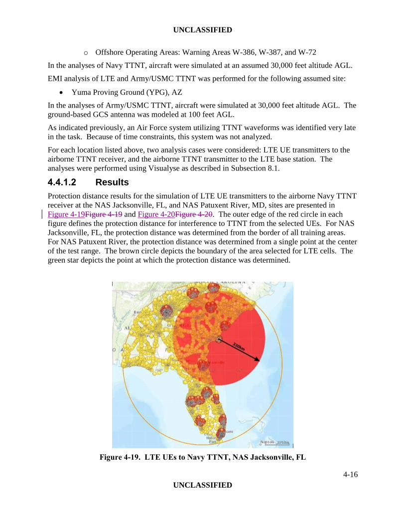
Protection distance results for the simulation of LTE UE transmitters to the airborne Navy TTNT
receiver at the NAS Jacksonville, FL, and NAS Patuxent River, MD, sites are presented in
Figure 4-19Figure 4-19 and Figure 4-20Figure 4-20. The outer edge of the red circle in each
figure defines the protection distance for interference to TTNT from the selected UEs. For NAS
Jacksonville, FL, the protection distance was determined from the border of all training areas.
For NAS Patuxent River, the protection distance was determined from a single point at the center
of the test range. The brown circle depicts the boundary of the area selected for LTE cells. The
green star depicts the point at which the protection distance was determined.
Figure 4-19. LTE UEs to Navy TTNT, NAS Jacksonville, FL

UNCLASSIFIED
4-17
UNCLASSIFIED
Figure 4-20. LTE UEs to Navy TTNT, NAS Patuxent River, MD
The simulated YPG environment is depicted in Figure 4-21Figure 4-21. The green star in the
figure depicts the location for the Army/USMC TTNT airborne and ground-based GCS.

UNCLASSIFIED
4-18
UNCLASSIFIED
Figure 4-21. Yuma Proving Ground Environment
Protection distance results for LTE UE transmitters to the airborne Army/USMC TTNT receiver
at YPG are presented in Figure 4-22Figure 4-22. The horizontal red line marks the -6 I/N
threshold. The light blue line indicates the aggregate I/N for the airborne Army/USMC TTNT
receiver as a function of the candidate protection distance in km (horizontal axis). It can be seen
that the light blue line drops below the -6 dB I/N threshold at a protection distance of 350 km.
Similarly, the green line indicates the aggregate I/N for the ground-based Army/USMC TTNT
receiver as a function of the candidate protection distance. It can be seen that the green line
drops below the -6 dB I/N threshold at a protection distance of 25 km.
Figure 4-22. UEs to Army/USMC TTNT, Yuma Proving Ground
Protection distance results for the simulation of the Navy TTNT transmitter to LTE base station
receivers at the NAS Jacksonville, FL, and NAS Patuxent River, MD, sites are presented in
Figure 4-23Figure 4-23 and Figure 4-24Figure 4-24. The red, blue, and green contours represent
the protection distances for 0, 60, and 180 degree off-axis angles, respectively. The green stars
are the three representative analysis points for the TTNT transmitter.

UNCLASSIFIED
4-19
UNCLASSIFIED
Figure 4-23. Navy TTNT to LTE Base Stations, NAS Jacksonville, FL
Figure 4-24. Navy TTNT to LTE Base Stations, NAS Patuxent River, MD
Protection distance results for the Army/USMC TTNT transmitter to LTE base station receivers

UNCLASSIFIED
4-20
UNCLASSIFIED
at the analyzed site are presented in Figure 4-25Figure 4-25. The red, blue, and green contours
represent the protection distances for 0, 60, and 180 degree off-axis angles, respectively. The
green star indicates the location for the Army/USMC TTNT transmitter.
Figure 4-25. Army/USMC TTNT to LTE Base Stations, Yuma Proving Ground
4.4.1.3 Summary
Protection distances for predicted interference between LTE and Navy TTNT for the NAS
Jacksonville, FL, and NAS Patuxent River, MD, sites range are summarized in Table 4-4Table
4-4. For the Navy TTNT transmitter to LTE base station receiver, the lower and upper values
are for base station antenna off-axis angles of 180 and 0 degrees, respectively.
Table 4-4. Summary of Protection Distances - LTE Versus Navy TTNT
From UEs to Navy TTNT Receiver From Navy TTNT Transmitter to
LTE Base Station Receiver
Analyzed Site
Estimated
Protection
Distance
(km)
Analyzed Site
Estimated
Range of
Protection
Distances (km)

UNCLASSIFIED
4-21
UNCLASSIFIED
NAS Jacksonville 330 NAS Jacksonville 291 - 440
NAS Patuxent River 360 NAS Patuxent River 310 - 430
Protection distances for predicted interference between LTE and Army/USMC TTNT for the
analyzed site range are summarized in Table 4-5Table 4-5. For Army/USMC TTNT transmitter
to LTE base station receiver, the lower and upper values are for base station antenna off-axis
angles of 180 and 0 degrees, respectively.
Table 4-5. Summary of Protection Distances - LTE Versus Army/USMC TTNT
From UEs to Army/USMC TTNT Receiver From Army/USMC TTNT
Transmitter to LTE Base Station
Receiver
Army/USMC
TTNT Site
Estimated
Protection
Distance (km),
Airborne
Receiver
Estimated
Protection
Distance (km),
Ground
Receiver
Army/USMC
TTNT Site
Estimated Range
of Protection
Distances (km)
Yuma Proving
Ground 350 25
Yuma Proving
Ground 260 - 415
Based on the results of the analyses for the three sites, it can be seen that TTNT systems and
LTE will interfere with each other unless protection distances are established. Improved
opportunities for LTE to share the 1755-1780 MHz band with TTNT systems within the sites and
protection distances provided are available if technical and operational mitigation approaches,
such as those described in Section 1.4.1, are developed.
4.4.1.4 Recommendations
Based on the results of the analyses, the following is recommended for Navy TTNT systems:
The additional studies/mitigation approaches outlined in Paragraph 1.4.1 should be
investigated to further quantify the feasibility of LTE sharing spectrum with Navy TTNT
systems.
If the protection distances as a result of additional studies are not sufficiently reduced,
establish protection zones for Navy TTNT and the Multifunctional Information
Distribution System for JTRS (MIDS-J) for the 1755-1850 MHz band at the seven

UNCLASSIFIED
4-22
UNCLASSIFIED
highest-priority DoD test and training installations/locations to minimize impacts to
operational training requirements. The list of seven highest-priority DoD
installations/locations can be provided.
For all other DoD installations/locations for test and training of Navy TTNT and MIDS-J,
truncate above 1780 MHz without requiring new spectrum assignments to replace the
ones in the 1755-1780 MHz band.
If protection zones and truncation are not acceptable, update the cost and performance
data related to the recommendation in the NTIA 1755-1850 MHz Report for relocation of
Navy TTNT and MIDS-J to an alternate comparable spectrum band.
Based on the results of the analyses, the following is recommended for Army/USMC TTNT
systems:
The additional studies/mitigation approaches outlined in Paragraph 1.4.1 should be
investigated to further quantify the feasibility of LTE sharing spectrum with
Army/USMC TTNT systems.
If the protection distances as a result of additional studies are not sufficiently reduced,
establish protection zones for Army/USMC TTNT for the 1755-1850 MHz band at the
six highest-priority DoD installations/locations for Army testing/training and the six
highest-priority DoD installations/locations for USMC testing/training to minimize
impacts to operational training requirements. The lists of highest-priority Army/USMC
installations/locations can be provided.
For all other DoD installations/locations for test and training of Army/USMC TTNT,
truncate above 1780 MHz without requiring new spectrum assignments to replace the
ones in the 1755-1780 MHz band.
If protection zones and truncation are not acceptable, evaluate the cost and performance
data for relocation to an alternate comparable spectrum band.
The following is recommended for Air Force TTNT systems:
The additional studies/mitigation approaches outlined in Paragraph 1.4.1 should be
investigated to further quantify the feasibility of LTE sharing spectrum with Air Force
TTNT systems.
If the protection distances as a result of additional studies are not sufficiently reduced,
establish protection zones for Air Force TTNT systems for the 1755-1850 MHz band at
the six highest-priority DoD test and training installations/locations to minimize impacts
to operational training requirements. The list of six highest-priority DoD
installations/locations can be provided.
For all other DoD installations/locations for test and training of Air Force TTNT, truncate
above 1780 MHz without requiring new spectrum assignments to replace the ones in the
1755-1780 MHz band.
If relocation of Air Force TTNT is required, evaluate the cost and performance data for
relocation to an alternate comparable spectrum band.

UNCLASSIFIED
4-23
UNCLASSIFIED
4.5 LITENING AND SNIPER CMDL
4.5.1 EMI Analysis
4.5.1.1 Analysis Parameters
EMI analysis of LTE and CMDL systems was performed for the following test and training
ranges:
Eglin Test Range (TR)
Nevada Test and Training Range (TTR)
Edwards AFB
In the simulation, the aircraft was assumed to be at points along the boundary defined by one or
more restricted airspaces:
Eglin TR: MOAs Eglin A (East and West), B, C, D, E, F
Nevada TTR: restricted airspaces R-4806, R-4807
Edwards AFB: restricted airspace complex R-2508
For CMDL on a LITENING pod, two analysis cases were considered for each simulated
location: LTE UE transmitters to the CMDL receiver, and the CMDL transmitter to the LTE base
station (the case of LTE UE transmitters to the ground-based ROVER receiving FMV from the
CMDL is described in another subsection).
For CMDL on a Sniper pod, the only analysis case that was considered was LTE UE transmitters
to the CMDL receiver.
All CMDL analyses were performed using Visualyse as described in Subsection 7.1.
In the analyses, the aircraft carrying CMDL was simulated at 30,000 ft altitude AGL.
4.5.1.2 Results
Protection distance results for LTE UE transmitters to the airborne LITENING CMDL receiver
at the Eglin TR, Nevada TTR, and Edwards AFB sites are presented in Figure 4-27Figure 4-27,
Figure 4-28Figure 4-28, and Figure 4-29Figure 4-29. The outer edge of a red circle in each
figure defines the individual protection distance for interference to CMDL from the selected
UEs. An individual red circle was defined for each point along the boundary of the training area.
The key for these three figures is depicted in Figure 4-26Figure 4-26.
Figure 4-26. Key for LTE UEs to LITENING CMDL Figures

UNCLASSIFIED
4-24
UNCLASSIFIED
Figure 4-27. LTE UEs to LITENING CMDL, Eglin Test Range
Figure 4-28. LTE UEs to LITENING CMDL, Nevada Test and Training Range
260 km
125 km
Protection distance radii: 255 to 300 km
Protection distance radii: 80 to 145 km

UNCLASSIFIED
4-25
UNCLASSIFIED
Figure 4-29. LTE UEs to LITENING CMDL, Edwards AFB
Protection distance results for the airborne LITENING CMDL transmitter to LTE base station
receivers at the Eglin TR, Nevada TTR, and Edwards AFB sites are presented in Figure
4-30Figure 4-30, Figure 4-31Figure 4-31, and Figure 4-32Figure 4-32. The red, blue, and green
contours represent the protection distances for 0, 60, and 180 degree off-axis angles,
respectively.
240 km
280 km
165 km 55 km
Protection distance radii: 95 to 245 km

UNCLASSIFIED
4-26
UNCLASSIFIED
Figure 4-30. LITENING CMDL to LTE Base Stations, Eglin Test Range
Figure 4-31. LITENING CMDL to LTE Base Stations, Nevada Test and Training Range
Figure 4-32. LITENING CMDL to LTE Base Stations, Edwards AFB
270 km
155 km
40 km
45 km
155 km
270 km

UNCLASSIFIED
4-27
UNCLASSIFIED
Protection distance results for LTE UE transmitters to Sniper CMDL receivers at the Eglin TR,
Nevada TTR, and Edwards AFB sites are presented in Figure 4-34Figure 4-34, Figure
4-35Figure 4-35, and Figure 4-36Figure 4-36. The outer edge of each blue circle in a figure
defines the individual protection distance for interference to CMDL from the selected UEs. An
individual protection blue circle was defined for each point along the boundary of the training
area. The key for these three figures is depicted in Figure 4-33Figure 4-33.
Figure 4-33. Key for LTE UEs to Sniper CMDL Figures
Figure 4-34. LTE UEs to Sniper CMDL, Eglin Test Range
260 km
Protection distance radii: 255 to 300 km

UNCLASSIFIED
4-28
UNCLASSIFIED
Figure 4-35. LTE UEs to Sniper CMDL, Nevada Test and Training Range
Figure 4-36. LTE UEs to Sniper CMDL, Edwards AFB
240 km
125 km
Protection distance radii: 80 to 145 km
Protection distance radii: 95 to 245 km

UNCLASSIFIED
4-29
UNCLASSIFIED
4.5.1.3 Summary
Protection distances for predicted interference between LTE and CMDL for the Eglin TR,
Nevada TTR, and Edwards AFB sites range are summarized in Table 4-6Table 4-6. For CMDL
transmitter to LTE base station receiver, the lower and upper values are for base station antenna
off-axis angles of 180 and 0 degrees, respectively.
Table 4-6. Summary of Protection Distances - LTE Versus CMDL
From UEs to CMDL Receiver From CMDL Transmitter to LTE
Base Station Receiver
LITENING
CMDL Site
Estimated
Range of
Protection
Distances (km)
LITENING
CMDL Site
Estimated Range
of Protection
Distances (km)
Eglin Test
Range 255 - 300
Eglin Test
Range 55 - 280
Nevada Test
and Training
Range
80 - 145
Nevada Test
and Training
Range
40 - 270
Edwards AFB 95 - 245 Edwards AFB 45 - 270
Sniper
CMDL Site
Estimated
Protection
Distance (km)
Sniper CMDL
Site
Estimated
Maximum
Distance (km)
Eglin Test
Range 255 - 300
Eglin Test
Range Not applicable
Nevada Test
and Training
Range
80 - 145
Nevada Test
and Training
Range
Not applicable
Edwards AFB 95 - 245 Edwards AFB Not applicable
Based on the results of the analyses for the three sites, it can be seen that CMDL systems and
LTE will interfere with each other unless protection distances are established. Therefore, it is

UNCLASSIFIED
4-30
UNCLASSIFIED
not feasible for LTE to share the 1755-1780 MHz band with CMDL systems within the sites and
protection distances provided unless technical and operational mitigation approaches, such as
those described in Section 1.4.1, are developed.
4.5.1.4 Recommendations
Based on the results of the analyses, the following is recommended for CMDL:
The additional studies/mitigation approaches outlined in Paragraph 1.4.1 should be
investigated to further quantify the feasibility of LTE sharing spectrum with CMDL
systems.
If band sharing is still not feasible after the investigation of possible mitigation
approaches, relocate to an alternate frequency band that is comparable to the 1755-1850
MHz band.
4.6 DRAGOON
4.6.1 EMI Analysis
4.6.1.1 Analysis Parameters
As indicated, the Dragoon may be used anywhere in the continental U.S. Three missions were
selected for the EMI analysis of LTE and Dragoon systems. The missions and a nearby city
potentially causing/affected by EMI are as follows:
Homeland Security mission (San Diego, CA)
Oil spill in the Gulf of Mexico (New Orleans, LA)
Atlantic superstorm (New York City, NY)
For each mission above, the aircraft carrying Dragoon was assumed to be flying in the following
restricted airspaces and warning areas:
Homeland Security mission: Kane E, W, S MOAs east of San Diego
Oil spill: Warning area W-453 in the Gulf of Mexico east of New Orleans
Atlantic superstorm: warning areas W-106A, W-106B, W-107B, W-107C, in the Atlantic
Ocean east of New York City and New Jersey
For each mission above, Dragoon VMR was assumed to be on the ground at the following
locations:
Homeland Security mission: east of San Diego, near the U.S.-Mexico border
Oil spill: east of the city of New Orleans
Atlantic superstorm: at Newark International Airport
For each location, two analysis cases were considered: LTE UE transmitters to the ground-based
VMR, and the airborne Dragoon transmitter to the LTE base stations. The analyses were
performed using Visualyse as described in Subsection 7.1. For the ground-based VMR, ITU
P.452-14 was used for ground-ground propagation losses. For the airborne Dragoon transmitter,
ITU P.528-3 was used for air-ground propagation losses.

UNCLASSIFIED
4-31
UNCLASSIFIED
In the analyses, the aircraft carrying Dragoon was simulated at 15,000 feet altitude AGL.
4.6.1.2 Results
Protection distance results for LTE UE transmitters to the ground-based Dragoon VMR at the
New York City, New Orleans, LA, and NY San Diego, CA, sites are presented in Figure
4-38Figure 4-38, Figure 4-39Figure 4-39, and Figure 4-40Figure 4-40. The key for these three
figures is depicted in Figure 4-37Figure 4-37.
Figure 4-37. Key for LTE UEs to Dragoon Figures
Figure 4-38. LTE UEs to Dragoon VMR, New York City, NY
88 km

UNCLASSIFIED
4-32
UNCLASSIFIED
Figure 4-39. LTE UEs to Dragoon VMR, New Orleans, LA
Figure 4-40. LTE UEs to Dragoon VMR, San Diego, CA
Protection distance results for the airborne Dragoon transmitter to LTE base station receivers at
45 km
94 km

UNCLASSIFIED
4-33
UNCLASSIFIED
the New York City, New Orleans, LA, and NY San Diego, CA, sites are presented in Figure
4-41Figure 4-41, Figure 4-42Figure 4-42, and Figure 4-43Figure 4-43. The red, blue, and green
contours represent the protection distances for 0, 60, and 180 degree off-axis angles,
respectively.
Figure 4-41. Dragoon to LTE Base Stations, New York City, NY
Figure 4-42. Dragoon to LTE Base Stations, New Orleans, LA
310 km
210 km
145 km
325 km 210 km
145 km

UNCLASSIFIED
4-34
UNCLASSIFIED
Figure 4-43. Dragoon to LTE Base Stations, San Diego, CA
4.6.1.3 Summary
Protection distances for predicted interference between LTE and Dragoon for the New York
City, New Orleans, LA, and NY San Diego, CA, sites are summarized in Table 4-7Table 4-7.
For Dragoon transmitter to LTE base station receiver, the lower and upper values are for base
station antenna off-axis angles of 180 and 0 degrees, respectively.
Table 4-7. Summary of Protection Distances - LTE Versus Dragoon
From UEs to Dragoon VMR From Dragoon Transmitter to LTE
Base Station Receiver
Dragoon Site
Estimated
Maximum
Protection
Distance (km)
Dragoon Site
Estimated Range
of Protection
Distances (km)
New York City,
NY 88
New York City,
NY 145 - 310
300 km 210 km
155 km

UNCLASSIFIED
4-35
UNCLASSIFIED
New Orleans, LA 45 New Orleans,
LA 145 - 325
San Diego, CA 94 San Diego, CA 155 - 300
Based on the results of the analyses for the three sites, it can be seen that Dragoon and LTE will
interfere with each other unless protection distances are established. Therefore, it is not feasible
for LTE to share the 1755-1780 MHz band with Dragoon within the sites and protection
distances provided unless technical and operational mitigation approaches, such as those
described in Section 1.4.1, are developed.
4.6.1.4 Recommendations
Based on the results of the analyses, the following is recommended for Dragoon:
The additional studies/mitigation approaches outlined in Paragraph 1.4.1 should be
investigated to further quantify the feasibility of LTE sharing spectrum with Dragoon
systems.
If band sharing is still not feasible after the investigation of possible mitigation
approaches, relocate to an alternate frequency band that is comparable to the 1755-1850
MHz band.
4.7 VORTEX
4.7.1 EMI Analysis
4.7.1.1 Analysis Parameters
EMI analysis of LTE and VORTEX systems was performed for the following test and training
ranges:
Eglin TR
Nevada TTR
Edwards AFB
In the simulation, the aircraft was assumed to be at points along the boundary defined by one or
more restricted airspaces:
Eglin TR: MOAs Eglin A (East and West), B, C, D, E, F
Nevada TTR: restricted airspaces R-4806, R-4807
Edwards AFB: restricted airspace complex R-2508
For each location, two analysis cases were considered: LTE UE transmitters to the VORTEX
airborne receiver, and the airborne VORTEX transmitter to the LTE base station. The analyses
were performed using Visualyse as described in Subsection 7.1.

UNCLASSIFIED
4-36
UNCLASSIFIED
In the analyses, the aircraft carrying VORTEX was simulated at 30,000 feet altitude AGL.
4.7.1.2 Results
Protection distance results for LTE UE transmitters to the airborne VORTEX receiver at the
Eglin TR, Nevada TTR, and Edwards AFB sites are presented in Figure 4-45Figure 4-45, Figure
4-46Figure 4-46, and Figure 4-47Figure 4-47. The outer edge of a purple circle in each figure
defines the individual protection distance for interference to VORTEX from the selected UEs.
An individual protection purple circle was defined for each point along the boundary of the
training area. The key for these three figures is depicted in Figure 4-44Figure 4-44.
Figure 4-44. Key for LTE UEs to VORTEX Figures
Figure 4-45. LTE UEs to VORTEX, Eglin Test Range
260 km
Protection distance radii: 255 to 300 km

UNCLASSIFIED
4-37
UNCLASSIFIED
Figure 4-46. LTE UEs to VORTEX, Nevada Test and Training Range
Figure 4-47. LTE UEs to VORTEX, Edwards AFB
240 km
125 km
Protection distance radii: 80 to 145 km
Protection distance radii: 95 to 245 km

UNCLASSIFIED
4-38
UNCLASSIFIED
Protection distance results for the airborne VORTEX transmitter to LTE base station receivers at
the Eglin TR, Nevada TTR, and Edwards AFB sites are presented in Figure 4-48Figure 4-48,
Figure 4-49Figure 4-49, and Figure 4-50Figure 4-50. The red, blue, and green contours
represent the protection distances for 0, 60, and 180 degree off-axis angles, respectively.
Figure 4-48. VORTEX to LTE Base Stations, Eglin Test Range
420 km
370 km
160 km

UNCLASSIFIED
4-39
UNCLASSIFIED
Figure 4-49. VORTEX to LTE Base Stations, Nevada Test and Training Range
Figure 4-50. VORTEX to LTE Base Stations, Edwards AFB
420 km
360 km
160 km
160 km
365 km
420 km

UNCLASSIFIED
4-40
UNCLASSIFIED
4.7.1.3 Summary
Protection distances for predicted interference between LTE and airborne VORTEX for the Eglin
TR, Nevada TTR, and Edwards AFB sites range are summarized in Table 4-8Table 4-8. For
VORTEX transmitter to LTE base station receiver, the lower and upper values are for base
station antenna off-axis angles of 180 and 0 degrees, respectively.
Table 4-8. Summary of Protection Distances - LTE Versus VORTEX
From UEs to VORTEX Receiver From VORTEX Transmitter to
LTE Base Station Receiver
VORTEX Site
Estimated Range
of Protection
Distances (km)
VORTEX Site
Estimated Range
of Protection
Distances (km)
Eglin Test Range 255 - 300 Eglin Test Range 160 - 420
Nevada Test and
Training Range 80 - 145
Nevada Test and
Training Range 160 - 420
Edwards AFB 95 - 245 Edwards AFB 160 - 420
Based on the results of the analyses for the three sites, it can be seen that VORTEX and LTE will
interfere with each other unless protection distances are established. Therefore, it is not feasible
for LTE to share the 1755-1780 MHz band with VORTEX within the sites and protection
distances provided unless technical and operational mitigation approaches, such as those
described in Section 1.4.1, are developed.
4.7.1.4 Recommendations
Based on the results of the analyses, the following is recommended for VORTEX:
The additional studies/mitigation approaches outlined in Paragraph 1.4.1 should be
investigated to further quantify the feasibility of LTE sharing spectrum with VORTEX
systems.
If band sharing is still not feasible after the investigation of possible mitigation
approaches, relocate to an alternate frequency band that is comparable to the 1755-1850
MHz band.

UNCLASSIFIED
4-41
UNCLASSIFIED
4.8 ROVER
4.8.1 EMI Analysis
4.8.1.1 Analysis Parameters
EMI analysis of LTE and ROVER systems was performed for the following locations:
Eglin TR
Nevada TTR
Edwards AFB
San Diego
New Orleans
New York City
The characteristics for the ROVER 5 transmitter are similar to those for CMDL (both systems
are manufactured by L-3 Communications Systems-West). Consequently, the protection
distances for an airborne ROVER 5 would be similar to those for CMDL and the case of
ROVER 5 transmitter to the LTE base station was not modeled.
To capture a ground-ground EMI case, the ROVER was assumed to be on the ground and in
receive mode only. For each location, only the case of LTE UE transmitters to the ROVER
receiver was considered. The analyses were performed using Visualyse as described in
Subsection 7.1. For the ground-based ROVER, ITU P.452-14 was used for ground-ground
propagation losses. In the analyses, the ROVER antenna was simulated at 2 meters AGL.
4.8.1.2 Results
Protection distance results for LTE UE transmitters to ground-based ROVERs receiving FMV
from TactiLink Eagle at the New York City, NY, New Orleans, LA, and NY San Diego, CA,
sites are presented in Figure 4-52Figure 4-52 through Figure 4-55Figure 4-55. The key for these
four figures is depicted in Figure 4-51Figure 4-51.
Figure 4-51. Key for LTE UEs to ROVER Figures

UNCLASSIFIED
4-42
UNCLASSIFIED
Figure 4-52. LTE UEs to ROVER, New York City, NY
Figure 4-53. LTE UEs to ROVER, New York City, NY (Expanded View)
20 km
20 km

UNCLASSIFIED
4-43
UNCLASSIFIED
Figure 4-54. LTE UEs to ROVER, New Orleans, LA
Figure 4-55. LTE UEs to ROVER, San Diego, CA
Protection distance results for LTE UE transmitters to ground-based ROVERs receiving FMV
from LITENING CMDL at the Eglin TR, Nevada TTR, and Edwards AFB sites are presented in
10 km
5 km

UNCLASSIFIED
4-44
UNCLASSIFIED
Figure 4-56Figure 4-56, Figure 4-57Figure 4-57, and Figure 4-58Figure 4-58. The key for these
three figures is depicted in Figure 4-51Figure 4-51.
Figure 4-56. LTE UEs to ROVER, Eglin Test Range
Figure 4-57. LTE UEs to ROVER, Nevada Test and Training Range
30 km
15 km

UNCLASSIFIED
4-45
UNCLASSIFIED
Figure 4-58. LTE UEs to ROVER, Edwards AFB
4.8.1.3 Summary
Protection distances for predicted interference between LTE and ground-based ROVER for the
selected sites range are summarized in Table 4-9Table 4-9.
Table 4-9. Summary of Protection Distances - LTE Versus ROVER
From UEs to ROVER
ROVER Site
Estimated
Maximum
Protection
Distance (km)
New York City, NY 20
New Orleans, LA 10
San Diego, CA 5
20 km

UNCLASSIFIED
4-46
UNCLASSIFIED
Eglin TR 15
Nevada TTR 30
Edwards AFB 20
Based on the results of the analyses for the six sites, it can be seen that LTE will interfere with
ROVER unless protection distances are established. Therefore, it is not feasible for LTE to share
the 1755-1780 MHz band with ROVER within the sites and protection distances provided unless
technical and operational mitigation approaches, such as those described in Section 1.4.1, are
developed.
4.8.1.4 Recommendations
Based on the results of the analyses, the following is recommended for ROVER:
The additional studies/mitigation approaches outlined in Paragraph 1.4.1 should be
investigated to further quantify the feasibility of LTE sharing spectrum with ROVER
systems.
If band sharing is still not feasible after the investigation of possible mitigation
approaches, relocate to an alternate frequency band that is comparable to the 1755-1850
MHz band.
A concern of the recommendations above is that course of action (COAs) for the ROVER system
are contingent on following any/all COAs related to SUAS.
UNCLASSIFIED
5-1
UNCLASSIFIED
5 DESCRIPTIONS OF FEDERAL SYSTEMS
This section includes descriptions of the systems analyzed in SWG-4.
In general, nominal technical characteristics for each system were taken from the DD Form
1494, Application for Equipment Frequency Allocation (also known as the J/F-12). Additional
parameters on the following topics were obtained from program subject matter experts:
System function
System operation
Operational locations (installations, bases)
Aircraft altitude
5.1 PGMS
5.1.1 System Description
PGMs can be used to attack single targets with one aircraft or one standoff weapon. PGMs
increase aircrew survivability by allowing the launch of weapons outside of any enemy anti-air
system threat envelope. PGMs require regular testing and training by operational units to
maintain operational readiness. Regular testing is also required for developmental activities as
the PGM are updated for new missions, threats, and capabilities.
Current PGMs affected by the reallocation of spectrum are used by the Air Force and the Navy.
PGM control links previously operating within the 1710-1850 MHz band were compressed so
they could operate in the 1755−1850 MHz band.
Current Air Force planning calls for discontinuing the use of PGMs that have RF links in the
1755−1850 MHz frequency range. A band sharing assessment is therefore not required.
The Navy PGM is an air-to-surface guided missile designed to provide the delivery platform
with a range capability of 150 nautical miles against a variety of land and sea targets. Aircraft-
missile communication is via RF data links. The data link transmitter on a pod carried by the
aircraft provides steering commands to the missile, allowing the weapon to be directed remotely
to a target by the launch aircraft or a remotely stationed controlling aircraft. The data link
receiver on the pod also processes real-time video from the weapon and outputs the video in a
format compatible with the aircraft cockpit display. There is also a data link system on the
missile that receives and processes steering commands and transmits video back to the aircraft.
5.1.2 Operation
Navy PGM usage within the US&P is limited to testing and training. Typical altitudes for
aircraft operating PGMs range up to 20,000 feet AGL.
5.2 TACTILINK EAGLE
5.2.1 System Description
The TactiLink Eagle is a legacy analog data link system installed on UH-72A Lakota light utility
helicopters and on Bell OH-58 Kiowa light helicopters as part of the Security and Support (S&S)

UNCLASSIFIED
5-2
UNCLASSIFIED
Mission Equipment Package (MEP).4,5
The TactiLink Eagle is a transmit-only system, relaying FMV and data to a receiver on the
ground (assumed to be a ROVER). The system does not have an airborne receiver.
5.2.2 Operation
The airborne platforms are Army National Guard assets and therefore can be utilized anywhere
within the state of issue. They can also be used in other states in support of Homeland Security,
law enforcement, disaster-relief, and protection of large-venue (e.g., Superbowl) missions.
Therefore, the airborne platform and the ground-based receiver can be anywhere in the US, not
necessarily in a training area.
Airborne platform altitudes are typically 500−5000 feet AGL.
5.3 JTRS AMF
5.3.1 System Description
JTRS AMF represents a family of multi-band/multi-mode software-defined radios, with planned
capabilities for providing communications within the 1200 MHz to 2 GHz frequency range. The
system will also have capabilities in the 225-960 MHz range. JTRS is intended to operate with
new advanced waveforms that have enhanced performance capabilities in both military and
civilian frequency bands, including the 1755–1850 MHz frequency band. Radios include the
Small Airborne Link 16 Terminal (SALT) and the Small Airborne Networking Radio (SANR)
operating the Soldier Radio Waveform (SRW) and the Wideband Networking Waveform
(WNW). JTRS AMF is in the design phase and is not currently operational.
Aircraft to be installed with JTRS AMF include AH-64E Apache, UH-60M/L Black Hawk, HH-
60M/L Black Hawk MEDEVAC, CH-47F Chinook, OH-58F Kiowa Warrior, MH-6 Little Bird,
and MQ-1C Gray Eagle UA.
The JTRS Small Airborne (SA) system, AN/ZRC-2, with the SRW was analyzed.
5.3.2 Operation
JTRS AMF functions include air-to-air and air-to-ground voice and data for ground combat
support. Major use is planned at a number of range and test facility bases: NTC at Ft. Irwin, CA;
Ft. Hood, TX; WSMR, NM; Ft. Bragg, NC; Ft. Polk, LA; NAWCWD China Lake, CA; YPG,
AZ; and Dugway Proving Ground (DPG), UT. Helicopter altitudes are 10,000 feet AGL and
below.
JTRS AMF operation is also planned at the associated ranges and designated MOAs of Ft.
Bragg, NC; Ft. Bliss, TX; Ft. Campbell, KY; Ft. Rucker, AL; Ft. Drum, NY; Ft. Carson, CO; Ft.
Lewis, WA; Ft. Wainwright, AK; and Schofield Barracks, HI.
5.4 TTNT
5.4.1 System Description 4 UH-72A S&S MEP Datalink. Powerpoint presentation. Utility Helicopters Project Office. Undated.
5 Online source: Lakota UH-72A MEP Upgrade Underway.
http://ngbcounterdrug.ng.mil/News/Pages/LakotaMEPUpgradeUnderway.aspx. 2009.

UNCLASSIFIED
5-3
UNCLASSIFIED
TTNT is a “modular, open, networking system that provides wireless connections, and the
underlying network management, to enable dynamic, machine-to-machine collaboration across
platforms.”6 TTNT will “permit 200 platforms or more separated by up to 100 nautical miles to
transfer sensor and other data (not voice) at a total TTNT system rate of at least 10 Mbps, with a
single platform having available up to a 2 Mbps rate, with ‘zero/very low’ latency define the
desired performance goal.”
Navy TTNT is designed for airborne platforms and involves air-to-air networking. Navy TTNT
systems are currently under development. From the DoD 2011 Report, the Navy plans to use the
MIDS-J radio in their combat aircraft as the host for the TTNT waveform.
The Army/USMC TTNT system includes airborne and ground-based elements, and is used for
air-air, air-ground, and ground-ground networking. The 1755-1850 MHz band is used for air-air
and air-ground networking; ground-ground operations only occur on UHF. The system is
currently in the experimental phase.
The Air Force TTNT system includes airborne elements, and is used for air-air networking. The
system is currently undergoing fly-off testing with the competitors.
5.4.2 Operation
Currently, the Navy TTNT network permits a maximum number of platforms with additional
numbers to be added in future years.
Army/USMC/Air Force TTNT systems are new systems currently under development and
operations details are not available.
Testing and training of TTNT systems will be accomplished at a number of ranges and sites
throughout the US&P.
5.5 LITENING AND SNIPER CMDL
5.5.1 System Description
Northrop Grumman’s AN/AAQ-28(V) LITENING targeting pod and Lockheed Martin’s Sniper
targeting pod are used for long-range detection, identification, and tracking of targets.7,8,9
Aircraft employing these targeting pods include F-16 Block 30, F-16 Block 40, A-10C, F-15E,
B-52H, and B-1B. Both pods include L-3’s CMDL system for relay of video/data.
Implementation of CMDL on the two targeting pods is essentially the same, but with the
following differences in function:
The LITENING CMDL is both transmit and receive: the downlink includes FMV/still
images to a ground unit, and the uplink includes still images extracted from inputs to the
ground unit.
6 Tactical Targeting Network Technology, TTNT “101” Brief. Powerpoint presentation. USN Chief of Naval
Operations. Distribution Statement A. Undated. 7 Sniper® Pod. Product data sheet. Lockheed Martin Corporation. 2011.
8 AN/AAQ-28(V) LITENING. Product data sheet. Northrop Grumman Corporation. 2012.
9 Sniper/LITENING ATPs & ATP-SE Spectrum Management Working Group. US Air Force Aeronautical Systems
Center. 12 Oct 2012 [FOUO].

UNCLASSIFIED
5-4
UNCLASSIFIED
The Sniper CMDL is receive-only: the uplink is a relatively narrowband still image.
Still images are relatively narrowband compared to the FMV. The ground unit is typically a
ROVER 3, 4, 5, or 6.
5.5.2 Operation
Typical altitudes for aircraft operating CMDL data links range from 20,000 feet AGL and above.
There are a number of locations in the US where Air Force, Navy, and Marine Corps units
operate LITENING and Sniper CMDL data links. These include Air Force Bases (AFBs), Air
National Guard (ANG) bases, Marine Expeditionary Units (MEUs), Marine Corps Air Stations
(MCAS), Naval Air Stations (NAS), Naval Air Weapons Station (NAWS), and International
Airports (IAPs).
5.6 DRAGOON
5.6.1 System Description
The Dragoon is a legacy data link system installed on Air National Guard RC-26B aircraft.
Dragoon is a transmit-only system, relaying FMV and data to a receiver on the ground. The
system does not have an airborne receiver. There are two types of ground-based receivers:
Messenger Smart Receiver is a fixed station, Veta Monitor Receiver (VMR) is a mobile station.
5.6.2 Operation
The system function is used mostly for homeland security missions, but has also been used for
law enforcement (local authorities up to and including federal authorities) and aerial surveillance
in the event of disasters. Information from the Dragoon POC indicates that the system may be
used anywhere in the continental U.S. Typical altitudes for RC-26 aircraft operating the
Dragoon data link are between 3,000 and 15,000 feet AGL.
5.7 VORTEX
5.7.1 System Description
L-3’s VORTEX data link system has functionalities similar to those for the CMDL: relay of
video/data on the downlink, video/data on the uplink. Airborne platforms employing VORTEX
include strike aircraft, Intelligence, Surveillance, and Reconnaissance aircraft, UAs, C-12, C-26,
OH-58, and Blue Devil reconnaissance airship.
5.7.2 Operation
Typical altitudes for aircraft operating VORTEX data links are less than 30,000 feet AGL. The
ground station is typically a ROVER 5 or 6. Operation is air-ground-air and air-air.
VORTEX can operate in L-band, S-band, C-band, and Ku-band. Only certain platforms (e.g.,
small UAs, OH-58, and C-26) downlink video/data on L-band frequencies. Uplink of data from
a ROVER ground station is typically on L-band or S-band.
5.8 ROVER
5.8.1 System Description

UNCLASSIFIED
5-5
UNCLASSIFIED
As indicated previously, some airborne data link systems transmit FMV to ground-based units
that receive the FMV using a ROVER Remote Video Terminal (RVT). Older ROVERs, such as
ROVER III and ROVER 4, are receive-only. Newer ROVERs, such as ROVER 5 and ROVER
6, have transmitting capabilities. The ROVER 6 transceiver includes the DDL Raven waveform.
5.8.2 Operation
As indicated previously, the ground station receiving FMV from Tactilink Eagle, CMDL, and
VORTEX was assumed to be a ROVER 5. ROVER systems are also used on airborne units such
as helicopters.

UNCLASSIFIED
6-1
UNCLASSIFIED
6 DESCRIPTION OF LTE SYSTEM
6.1 NETWORK
This section provides details on the proposed LTE cellular network as obtained from documents
presented to the CSMAC WG-5.10,11,12
The LTE system is the newest implementation for mobile broadband service based on standards
from the 3rd Generation Partnership Project (3GPP). For proposed sharing, the uplink frequency
band from mobile hand-held user equipment (UE) to a base station (BS) is 1755–1780 MHz, and
the paired frequency division duplex (FDD) frequency band for downlink from the BS to the
UEs is 2155–2180 MHz.
The LTE cellular network is based on a coverage-centric solution rather than a capacity-centric
solution. Every base station in the network uses the same frequency, a concept referred to as
universal frequency reuse. Each cell is divided into three angular sectors for coverage over 360
degrees in azimuth. Directional sector antennas at a BS provide azimuthal coverage, and the
main lobe of radiation is directed below the horizon using a mechanical or electrical downtilt.
For a 10-MHz channel, the maximum number of simultaneously transmitting UEs is six per
sector or eighteen per BS.
Initial plans for deployment of LTE [11] involved cells installed within two concentric circles
centered on a city or town. The inner circle (referred to as an urban/suburban area) consisted of
a dense laydown of cells where the proposed inter-site distance between base stations was 1.732
km. The outer circle (for a rural area) had a less-dense laydown of cells with an inter-site
distance of 7 km.
Commercial wireless industry representatives subsequently made available a more-realistic
geographic laydown of cells. This laydown was based on an actual commercial wireless industry
network of base station locations for urban/suburban and rural environments in the U.S., but with
the locations slightly randomized.
From [10], the uplink transmission scheme is single-carrier frequency-division multiple access
(SC-FDMA). Advantages to this scheme are higher uplink throughput, improved coverage and
cell-edge performance, lower terminal cost, and improved battery life. The time-domain
structure is 10-millisecond frames consisting of ten subframes, each one millisecond in duration.
Each subframe consists of two slots of length 0.5 millisecond, where each slot includes seven
orthogonal frequency-division multiplexing symbols.
A physical resource block (PRB) consists of twelve 15-kHz subcarriers during one slot, for a
total of 180 kHz. The LTE specification supports any bandwidth in the range of six PRBs (1.08
MHz) to 100 RBs (18.0 MHz) in steps of one PRB. However, 3GPP has adopted specific
channel bandwidths, and a 10-MHz LTE channel bandwidth (50 PRBs for a transmission
bandwidth of 9 MHz) has been proposed for the sharing study.
10
LTE Introduction, Presentation to CSMAC WG-5 August 2-3, 2012. 11
Baseline LTE Uplink Characteristics, CSMAC Working Groups – LTE Characteristics Subgroup, 12 November
2012. 12
Uplink Transmit Power Analysis for LTE, 27 August 2012.

UNCLASSIFIED
6-2
UNCLASSIFIED
From [12], LTE is a packet-switched network that dynamically allocates PRBs to UEs in each 1-
millisecond transmit time interval (TTI). The UE transmitter power, and the resultant power
spectral density (PSD) at a point in space, are also controlled. The maximum number of UEs
that can transmit at a given instant is limited and not all UEs in a sector can transmit at the same
time. The LTE uplink multiplexing scheme is depicted in Figure 6-1Figure 6-1.
From [12]
Figure 6-1. LTE Uplink Multiplexing Scheme
For analysis purposes, the network is assumed to be 100% loaded, where all PRBs are occupied
at all times.
6.2 BASELINE CHARACTERISTICS
UE power control is a technique used in LTE to mitigate for the large variation in the
propagation loss across the sector as well as to reduce the amount of interference to other cells.
In general, UEs at the edge of the cell are controlled to transmit at higher power than UEs closer
to the center. UE transmitter power ranges from -40 dBm to +23 dBm. Since the UE maximum
antenna gain is -3 dBi, the effective isotropic radiated power (EIRP) ranges from -37 dBm to +20
dBm. The LTE Baseline document [11] provides cumulative distribution function (CDF) plots
of the total EIRP for a UE in urban/suburban and rural environments.
The LTE Baseline document also includes the following data:
UE transmitter emission spectrum masks for various channel bandwidths. For each
bandwidth, the mask data consists of emission limits (i.e., maximum emission levels) for

UNCLASSIFIED
6-3
UNCLASSIFIED
various difference frequencies (Δf’s). The emission limit values are in terms of dBm and
are relative to the maximum transmitter power of 23 dBm. The Δf’s are defined with
respect to the edge of the occupied bandwidth.
BS receiver specification data such as reference sensitivity data for various channel
bandwidths, the noise figure, and an adjacent-channel selectivity value. The selectivity
value is in terms of the interfering signal mean power relative to the desired signal mean
power, both in dBm.
Specification data for the BS sector antenna. The data include the maximum gain, -3 dB
beamwidths in the azimuth and elevation planes, downtilt angle in the elevation plane,
polarization, antenna height above ground level (AGL), and miscellaneous system loss
(cable, insertion, etc.).
The reference to the ITU document that may be used to model the pattern of the BS
sector antenna and obtain gains at off-axis angles in the azimuth and elevation planes.

UNCLASSIFIED
7-1
UNCLASSIFIED
7 ANALYSIS METHODOLOGIES
This section includes descriptions of the methodologies used in the analyses for WG-5 DoD
systems.
7.1 VISUALYSE
7.1.1 Introduction
A commercially available software analysis tool called “Visualyse”13
was used for sharing
analyses of a number of DoD systems. Two different types of analyses were performed: the
DoD system receiver as potential victim of EMI, and the DoD system transmitter as potential
source of EMI. These two types are described below.
7.1.2 DoD Systems as Victim of EMI
For the analysis of a DoD system as a potential victim of EMI, specific locations in the United
States were selected for analysis. The selection of the specific locations was based on the
expected operational usage of the system. In some cases, military test and training ranges were
selected, and in other cases, locales where the aircraft could be flown were selected. For each
location, the aircraft was assumed to be operational within a specific area, and points along the
boundary of the area were selected to represent locations of the DoD system receiver. The
aircraft was also assumed to be operational at a specific altitude. In Visualyse, the receiving
system was located at each of these points.
For the analyses, commercial wireless industry made available a realistic network of base station
locations for urban/suburban and rural environments in the U.S. For each range to be analyzed,
urban/suburban and rural base station locations in the vicinity of the DoD receiver site were
selected. The radius for the select was based on the distance to the radio horizon from the
aircraft at its operational altitude.
At each base station location, UE transmitters were assumed to be positioned on the ground at
the coordinates of the base station tower, where the antenna height of each UE was 1.5 m AGL.
For each location of the DoD system receiver, the undesired received power and the I/N due to
each UE was computed in the following way. UE transmitters were sequentially selected for
analysis. Co-channel conditions were assumed for the transmitter and receiver frequencies (i.e.,
both were assumed to be tuned to the same frequency). A random value of the EIRP for the UE
was evaluated using data provided in the LTE baseline document. The bandwidth for the UE
transmitter was set at 1.67 MHz. Visualyse computed the propagation path and distance between
the points representing the UE and the receiving antenna. The propagation loss along this path
was evaluated using an appropriate model (ITU-R 528-3 for ground-air paths or ITU-R 452-14
for ground-ground paths). Since the receiving antennas of interest are simple types (e.g.,
monopoles and dipoles), the gain for these types of antennas was evaluated using an approximate
model.14
Receiver system loss (e.g., cable loss, insertion loss, etc.) was assumed to be 2 dB. The
frequency dependent rejection (FDR) of the UE signal due to the receiver’s IF stage bandwidth
13
Visualyse Professional - make life easier, improve your output.
http://www.transfinite.com/content/professional.html. 2013. 14
J. Kraus, Antennas, 2nd
edition, McGraw-Hill.

UNCLASSIFIED
7-2
UNCLASSIFIED
was computed. For cases where the transmitter emission bandwidth was wider than the
receiver’s IF bandwidth, the FDR was non-zero. The undesired received power in dBW at the
narrowest IF stage of the receiver was computed. The I/N was computed by subtracting the
receiver system noise level from the undesired received power, both in dBW.
The Visualyse analysis was many-on-one (i.e., the analysis consisted of the potential EMI from
the collection of UE transmitters to a receiver), so the level of aggregate undesired received
power was calculated by summing the individual received power values in Watts.
Because of the large number of UEs in the vicinity of the victim receiver, Visualyse run-time for
some environments was very large. To reduce run-time, the number of UEs per cell that could
contribute to the aggregate received power was adjusted based on the bandwidth of the receiver.
For example, for a receiver bandwidth of 3 MHz, the receiver would accept power from two UEs
(each of which is 1.67 MHz) per sector.
The protection distance is the minimum distance between a DoD system receiver and the
laydown of UEs at which EMI to the DoD receiver would not be expected to occur. For each
location of the DoD system receiver, the protection distance between the receiver and the
laydown of UEs was evaluated as follows. Visualyse permits the user to set an exclusion radius
value where UEs at distances smaller than the input radius are not included in the I/N
calculations. Visualyse also has a capability for sequentially repeating an analysis for a series of
time samples. Since UE transmitter power is a random variable, the aggregate undesired
received power, and the I/N, will vary over the time samples. The aggregate I/N was computed
for a series of time samples and collected in a file saved by Visualyse. From this file, the
average aggregate I/N was then computed and compared to the receiver I/N interference
threshold. Based on the comparison, the exclusion radius was iteratively varied until the average
aggregate I/N was equal to the I/N threshold. The protection distance was set to the exclusion
radius.
Plots of protection distance results were generated by using ArcGIS Explorer. The
urban/suburban and rural locations, along with the DoD receiver locations, were imported into
ArcGIS Explorer. The protection distance for each DoD receiver location was plotted as a color-
coded circle.
7.1.3 DoD System as Source of EMI
The analysis of a DoD system as a potential source of EMI was essentially the same as that
described in the previous subsection. A major difference was that the analysis was one-on-one
(i.e., the DoD system transmitter to one LTE base station receiver).
For these analyses, the pattern for the LTE base station sectoral antenna with a downtilt angle of
3 degrees in the elevation plane was modeled using equations from ITU-R F.1336-3. An
elevation plane cut through the main lobe (azimuth angle equal to 0 degrees) was obtained by
computing the gain for elevation angles ranging from -90 to 90 degrees. A 3D pattern was
created in Visualyse by entering this elevation plane cut at four azimuth angles, 0, 90, 180, and
270 degrees. Therefore, for any propagation path azimuth and elevation angles, Visualyse would
compute the gain based on the elevation plane cut. Elevation plane cuts for off-axis azimuth
angles equal to 60 and 180 degrees were similarly obtained.
DoD transmitting systems were modeled in Visualyse at points along the boundary of each

UNCLASSIFIED
7-3
UNCLASSIFIED
analyzed military range or area.
For these analyses, Visualyse has a capability called Area Analysis, where the user defines a
rectangular area over a geographic region that includes the set of transmitting system locations.
The user also selects a value for the I/N threshold (e.g., -6 dB). For each transmitter location, a
receiver (in this case, the LTE base station receiver) is incrementally positioned at points within
the area. The realistic network of base station locations was not employed in the Area Analysis.
At each point for the receiver, Visualyse computes the undesired received power and the I/N.
When all points have been analyzed, Visualyse plots a contour representing the distance from the
transmitters at which the I/N is equal to the I/N threshold. This contour represents the protection
distance within which EMI to LTE base station receivers would not be expected. The distance
from the transmitter location to a point on the contour was determined using a Visualyse feature.
For each location of the LTE BS receiver, the undesired received power and the I/N due to each
DoD system transmitter was computed in a fashion similar to that described in the previous
subsection, with differences as follows. The transmitter power and antenna gain for the DoD
transmitter were both set to the maximum. System loss at the transmitter (e.g., cable loss,
insertion loss, etc.) was included where appropriate. The bandwidth for the LTE BS receiver
was set at 10.0 MHz. Visualyse computed the propagation path between the points representing
the DoD transmitting system and the LTE base station antenna, and the air-ground propagation
loss along this path was evaluated using the ITU-R 528-3 propagation model. Visualyse also
computed the azimuth and elevation angles from the transmitting antenna to the BS sectoral
antenna. For the LTE base station receiving antenna gain, three cases based on the azimuth
angle of the main lobe relative to the azimuth angle in the direction of a transmitter were
analyzed. The three cases are: 0 degrees (main lobe azimuth in the direction of a transmitter), 60
degrees (main lobe at 60-degree offset), and 180 degrees (back lobe in the direction of a
transmitter). In all three cases, the main lobe is tilted downward by three degrees in the elevation
plane, so the main lobe doesn’t actually point toward the DoD transmitting antenna. Receiver
system loss was assumed to be 2 dB [11]. FDR was computed and the value was not zero when
the DoD system emission bandwidth was greater than the bandwidth of the LTE BS receiver.
Plots of protection distance results were generated as follows using a multi-step process. The
Visualyse-generated data for a contour was written to a kml file which was imported into Google
Earth. Using Google Earth, the contour data was subsequently written to a Google Earth kmz
file which was imported into ArcGIS Explorer along with the urban/suburban and rural LTE
locations. Three color-coded protection distance contours for 0, 60, and 180-degree base station
off-axis angles were plotted using ArcGIS Explorer.
7.2 Excel
7.2.1 Introduction
The methodologies employed by Boeing and Raytheon for the analysis of PGMs are described in
this subsection.
7.2.2 PGM System as Victim of EMI
The Raytheon analysis of potential EMI to the PGM receiver was similar to the analysis of the
other DoD system receivers as described above. Differences are noted in the following
paragraphs.

UNCLASSIFIED
7-4
UNCLASSIFIED
The many-on-one analysis was accomplished using an Excel spreadsheet, where the locations of
urban/suburban and rural base stations were spaced at increments of 1.732 km for an
urban/suburban deployment and increments of 7 km for a rural deployment as defined in the
LTE baseline document for a grid laydown. Eighteen UE transmitters were positioned at each
base station location. The antenna height for all UEs was 1.5 meters AGL.
The PGM system receiver was assumed to be at an altitude of 20,000 feet AGL.
The center frequency for each UE transmitter and the receiver were assumed to be the same. The
median UE EIRP was +8 dBm for the rural emitters and -3 dBm for the urban emitters as
determined from the LTE baseline document. The propagation loss between the UE transmitter
and the PGM receiver was evaluated using ITU-R 528-3. An I/N of -6 dB was employed as the
PGM receiver threshold. Additional system losses were assumed to be 2 dB. The received
power in dBm due to each UE transmitter was computed, and the aggregate received power due
to the collection of UEs was computed by summing the individual received power values in
Watts and converting to dBm. The protection distance was iteratively calculated using the power
level required at the PGM receiver to avoid interference based on the I/N ratio and using the
ITU-R-528-3 propagation loss tables. The number of base stations and aggregate UE
transmitters were also adjusted based on the protection distance determined during the iterative
process. The number of cell towers was reduced to compensate where a portion of the
aircraft/PGM operational mission was occurring over a large body of water.
7.2.3 PGM System as Source of EMI
The Boeing analysis of potential EMI to LTE base stations by the PGM transmitter was similar
to the analysis of the other DoD system transmitters as described above. Differences are noted in
the following paragraphs.
Several cases were analyzed for the PGM system transmitter. For ground testing, the transmitter
was assumed to be located at 5 feet AGL and for test or training flights the transmitter was
assumed to be located at an altitude of 10000 feet AGL. For simulated ground testing, low-
power mode was used for the transmitter. For simulated flights, high-power mode was used.
Three base station antenna off-axis angles were simulated: 0, 60, and 180 degrees.
The one-on-one analysis was accomplished using an Excel spreadsheet. The transmitter and
receiver were both assumed to be tuned to the same frequency. The level of received power at
the LTE base station was calculated using the maximum EIRP for the PGM system transmitter,
15 dBi receive antenna gain (includes 3-degree down-tilt pattern effects), and transmitter-
receiver propagation loss evaluated using ITU-R 528-3. The I/N was computed by subtracting
the receiver system noise level from the undesired received power, both in dBm.
The protection distance was determined by iteratively adjusting the transmitter-receiver distance
in the spreadsheet until the I/N was equal to the I/N threshold (-6 dB).
7.3 RECEIVED POWER
The undesired received power, I, was computed using the following equation:
FDRLLGLGLPI miscRRPTTT (Eqn 7-1)

UNCLASSIFIED
7-5
UNCLASSIFIED
where
I = undesired received power, in dBm
PT = transmitter power of the undesired source, in dBm
LT = loss at the transmitter (e.g., system, cable), in dB
GT = transmit antenna gain of the undesired source, in dBi. GT is the gain in the
direction of the propagation ray path.
LP = propagation loss, in dB. LP is evaluated at the receive frequency, and includes
any additional losses (diffraction, reflection, etc.) along the ray path.
GR = receive antenna gain, in dBi. GR is the gain in the direction of the propagation ray
path.
LR = loss at the receiver (e.g., system, cable), in dB
Lmisc = total of any miscellaneous loss, in dB
FDR = frequency dependent rejection, in dB
7.4 AGGREGATE RECEIVED POWER
Aggregate received power due to multiple UEs was calculated using the following equation:
M
j
jagg II1
10log1030 (Eqn 7-2)
where
Iagg = aggregate received power, in dBm
M = number of UEs
Ij = undesired received power from a single UE, Watts
7.5 RECEIVER EFFECTIVE NOISE
The receiver’s thermal noise power is given by:
kTBnr (Eqn 7-3)
where
nr = the receiver’s thermal noise power, in watts
k = Boltzmann’s constant, which is 1.38 x 10⁻²³ J/K
T = the absolute temperature, in degrees Kelvin. The standard value of 290 K (62.3
degrees Fahrenheit) was used for T
B = the receiver’s bandwidth, in Hertz
Man-made, atmospheric, and galactic noise levels were assumed to be negligible at L-band

UNCLASSIFIED
7-6
UNCLASSIFIED
frequencies. The effective receiver input noise power was computed as follows:
nr fnn (Eqn 7-4)
where
n = the receiver’s effective input noise power, in watts
fn = the receiver’s noise factor, unitless
The effective receiver input noise power, N, in dBm was computed as follows:
nN log1030 (Eqn 7-5)
7.6 RECEIVER THRESHOLD
The receiver threshold, i.e., the maximum allowed undesired received power, IT in dBm, is given
by:
6 NIT (Eqn 7-6)
In general, the interference threshold was based on a criterion of 6 dB below the receiver noise
level although some SWGs may use a different value for the threshold.
7.7 FREQUENCY DEPENDENT REJECTION
Given the tuned frequencies of the transmitter and the receiver, FDR is the rejection provided by
the receiver’s IF stage to an undesired, possibly off-tuned, signal. The transmitter emission
spectrum data and the receiver IF-stage selectivity data are inputs to the calculation of the FDR.
For co-channel conditions, if the transmitter emission spectrum -3 dB bandwidth is narrower
than the receiver IF-stage -3 dB bandwidth, the receiver accepts all the power of the transmitted
signal. On the other hand, if the transmitter emission spectrum bandwidth is wider than the
receiver IF-stage bandwidth, the transmitted signal is attenuated and the FDR is given by the
following:
- Rx
Tx
BW
BWFDR 10log10
(Eqn 7-7)

UNCLASSIFIED
8-1
UNCLASSIFIED
8 REFERENCES
[1] Spectrum Reallocation Feasibility Study, 1755-1850 MHz Band, Sep 8, 2011, Rev 1,
Department Of Defense, December 12, 2011.
[2] An Assessment of the Viability of Accommodating Wireless Broadband in the 1755 – 1850
MHz Band, U.S. Department of Commerce, March 2012.
[3] Propagation curves for aeronautical mobile and radionavigation services using the VHF,
UHF and SHF bands, Recommendation ITU-R P.528-3, International Telecommunication
Union, February 2012.
[4] Prediction procedure for the evaluation of interference between stations on the surface of the
Earth at frequencies above about 0.1 GHz, Recommendation ITU-R P.452-14, International
Telecommunication Union, October 2009.
[5] Reference radiation patterns of omnidirectional, sectoral and other antennas in point-to-
multipoint systems for use in sharing studies in the frequency range from 1 GHz to about 70
GHz, Recommendation ITU-R F.1336-3, International Telecommunication Union, March 2012.
[6] UH-72A S&S MEP Datalink. Powerpoint presentation. Utility Helicopters Project Office.
Undated.
[7] Online source: Lakota UH-72A MEP Upgrade Underway.
http://ngbcounterdrug.ng.mil/News/Pages/LakotaMEPUpgradeUnderway.aspx. 2009.
[8] Tactical Targeting Network Technology, TTNT “101” Brief. Powerpoint presentation. USN
Chief of Naval Operations. Distribution Statement A. Undated.
[9] Sniper® Pod. Product data sheet. Lockheed Martin Corporation. 2011.
[10] AN/AAQ-28(V) LITENING. Product data sheet. Northrop Grumman Corporation. 2012.
[11] Sniper/LITENING ATPs & ATP-SE Spectrum Management Working Group. US Air Force
Aeronautical Systems Center. 12 Oct 2012 [FOUO].
[12] LTE Introduction, Presentation to CSMAC WG-5 August 2-3, 2012.
[13] Baseline LTE Uplink Characteristics, CSMAC Working Groups – LTE Characteristics
Subgroup, 12 November 2012.
[14] Uplink Transmit Power Analysis for LTE, 27 August 2012.
[15] Visualyse Professional - make life easier, improve your output.
http://www.transfinite.com/content/professional.html. 2013.
[16] J. Kraus, Antennas, 2nd
edition, McGraw-Hill.

UNCLASSIFIED
9-1
UNCLASSIFIED, DRAFT
9 ACRONYMS
3GPP 3rd Generation Partnership Project
ACMI Air Combat Maneuvering Instrumentation
ACTS Air Combat Training System
AFB Air Force Base
AGL Above Ground Level
AMF Airborne and Maritime/Fixed
AMT Aeronautical Mobile Telemetry
ANG Air National Guard
ARNG Army National Guard
BS Base Station
C2 Command and Control
CDF Cumulative Distribution Function
CMDL Compact Multiband Data Link
COA Course Of Action
CSMAC Commerce Spectrum Management Advisory Committee
CTS Combat Training System
dB Decibel
dBi Decibel above Isotropic
dBm Decibel relative to 1 milliwatt (10^-3 W)
DDL Digital Data Link
DOC Department of Commerce
DoD Department of Defense
EIRP Effective Isotropic Radiated Power
EMI Electromagnetic Interference
FCC Federal Communications Commission
FDD Frequency Division Duplex
FDR Frequency-Dependent Rejection
FMV Full Motion Video
FOUO For Official Use Only
GCS Ground Control Station

UNCLASSIFIED
9-2
UNCLASSIFIED, DRAFT
HRV High-Resolution Video
Hz Cycles per second
I/N Interference to Noise Ratio
IAP International Airport
IF Intermediate Frequency
ITU International Telecommunications Union
ITU-R International Telecommunication Union Radiocommunication Sector
JTRS Joint Tactical Radio System
kHz Kilohertz (10^3 Hertz)
LTE Long Term Evolution
Mbps Megabits per second (10^6 bits per second)
MCAS Marine Corps Air Station
MEP Mission Equipment Package
MEU Marine Expeditionary Unit
MHz Megahertz (10^6 Hertz)
MIDS Multifunctional Information Distribution System
MOA Military Operational Area
mW Milliwatt (10^-3 Watts)
NACTS Nellis Air Combat Training System
NAS Naval Air Station
NAWS Naval Air Weapons Station
NTC National Training Center
NTIA National Telecommunications and Information Administration
P5 CTS P5 Combat Training System
PGM Precision Guided Munition
PPSG Policy and Plans Steering Group
PRB Physical Resource Block
PSD Power Spectral Density
RF Radio Frequency
ROVER Remote Operations Video Enhanced Receiver
RVT Remote Video Terminal

UNCLASSIFIED
9-3
UNCLASSIFIED, DRAFT
S&S Security and Support
SA Small Airborne
SC-FDMA Single-Carrier Frequency-Division Multiple Access
SRW Soldier Radio Waveform
SUAS Small Unmanned Aerial System
SWG Sub-Working Group
TACTS Tactical Aircrew Combat Training System
TCTS Tactical Combat Training System
TM Telemetry
TR Test Range
TTI Transmit Time Interval
TTR Test and Training Range
TTNT Tactical Targeting Network Technology
UA Unmanned Aircraft
UAS Unmanned Aerial System
UE User Equipment
USMC United States Marine Corps
US&P United States and its Possessions
VMR Veta Monitor Receiver
VORTEX Video ORiented Transceiver for EXchange of information
W Watts
WG Working Group
WSMR White Sands Missile Range

Summary Report:
Litéra® Change-Pro TDC 7.0.0.242 Document Comparison done on
6/11/2013 6:16:14 PM
Style Name: Default Style
Original Filename: CSMAC WG-5 SWG-PGM-Misc Report
05Jun2013_v4[1].docx
Modified DMS: dm://WRFMAIN/13601649/1
Changes:
Add 3
Delete 2
Move From 0
Move To 0
Table Insert 0
Table Delete 0
Embedded Graphics (Visio, ChemDraw, Images etc.) 0
Embedded Excel 0
Format Changes 0
Total Changes: 5