Embed Size (px)
Citation preview
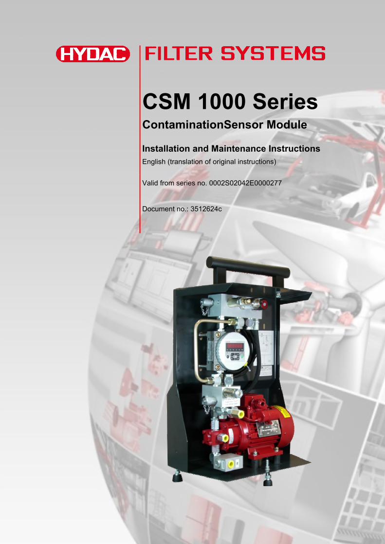
CSM 1000 Series ContaminationSensor Module
Installation and Maintenance Instructions English (translation of original instructions)
Valid from series no. 0002S02042E0000277
Document no.: 3512624c

Imprint
CSM 1000 Series en 2 / 48
MoWa CSM1000 3512624c en-us 2012-11-26.doc 2012-11-23
Imprint
Publisher and responsible for the content:
HYDAC FILTER SYSTEMS GMBH
Postfach 1251
66273 Sulzbach / Saarland
Germany
Telephone: +49 (0)6897 509 01
Telefax: +49 (0)6897 509 846
E-mail: [email protected]
Homepage: www.hydac.com
Court of Registration: Saarbrücken, HRB 17216
Executive director: Mathias Dieter, Dipl.Kfm. Wolfgang Haering
Documentation Representative
Mr. Günter Harge
c/o HYDAC International GmbH, Industriegebiet, 66280 Sulzbach / Saar
Telephone: ++49 (0)6897 509 1511
Telefax: ++49 (0)6897 509 1394
E-mail: [email protected]
© HYDAC FILTER SYSTEMS GMBH
All rights reserved. No part of this work may be reproduced in any form (print, photocopy or by other means) or processed, duplicated or distributed using electronic systems without the written consent of the publisher. These documents have been created and inspected with the greatest care. However, errors cannot be ruled out completely.
All details are subject to technical modifications. Technical specifications are subject to change without notice.

Content
CSM 1000 Series en 3 / 48
MoWa CSM1000 3512624c en-us 2012-11-26.doc 2012-11-23
Content
Imprint............................................................................................................2
Documentation Representative ...................................................................2
Content ..........................................................................................................3
Preface...........................................................................................................5
Technical Support........................................................................................6
Modifications to the Product ........................................................................6
Warranty ......................................................................................................6
Using the Documentation ............................................................................7
Safety Information and Instructions............................................................8
Hazard symbols...........................................................................................8
Signal words and their meaning in the safety information and instructions ..................................................................................................8
Structure of the safety information and instructions...................................10
Observe regulatory information .................................................................10
Proper/Designated Use .............................................................................11
Improper use or use deviating from intended use......................................11
Qualifications of personnel / target group ..................................................13
Wear suitable clothing ...............................................................................14
Unpacking the CSM ....................................................................................14
Transporting the CSM ................................................................................15
Storing the CSM..........................................................................................16
Checking the Scope of Delivery ................................................................17
CSM Characteristics ...................................................................................18
CSM components........................................................................................19
Hydraulic Schematic...................................................................................20
Dimensions..................................................................................................21
Drilling template for wall mounting.............................................................22
Hydraulic Connection of the CSM .............................................................22
Hydraulic Connectors ................................................................................22
Notes on piping / hosing ............................................................................23
Suction port connection - IN ...................................................................24

Content
CSM 1000 Series en 4 / 48
MoWa CSM1000 3512624c en-us 2012-11-26.doc 2012-11-23
Return port connection - OUT ................................................................25
Leakage oil connection - LEAKAGE (only with CSM1xxx-2 ...) ..............25
Magnetic coupling (only CSM 1xxx-4…).................................................26
Electrical Connection of the CSM..............................................................27
Electrical connection of the ContaminationSensor CS1000.......................28
Electrical connection of the AquaSensor AS1000 .....................................28
Starting up the CSM....................................................................................29
Adjusting the counter balance valve.........................................................29
Required tools and measuring instruments ...............................................29
Performing Maintenance ............................................................................34
Clean the suction screen ...........................................................................35
Disposing of the CSM.................................................................................37
Errors and Troubleshooting.......................................................................37
Spare parts ..................................................................................................38
Accessories.................................................................................................41
Plugs ......................................................................................................41
Connection cable, shielded ....................................................................41
Connection cable....................................................................................41
Connection cable....................................................................................42
Customer service........................................................................................42
Technical data .............................................................................................43
Model Code..................................................................................................45

Preface
Preface
For you, as the owner of a product manufactured by us, we have produced this manual, comprising the most important instructions for its operation and maintenance.
It will acquaint you with the product and assist you in using it as intended in an optimal manner.
Keep this documentation in the vicinity of the product for immediate reference.
Note that the information on the unit's engineering contained in the documentation was that available at the time of publication.There may be deviations in technical details, figures, and dimensions as a result.
If you discover errors while reading the documentation or have additional comments or suggestions, contact us at:
HYDAC FILTER SYSTEMS GMBHTechnische DokumentationPostfach 12 5166273 Sulzbach / Saar Germany
CSM 1000 Series en 5 / 48
MoWa CSM1000 3512624c en-us 2012-11-26.doc 2012-11-23
Preface
CSM 1000 Series en 6 / 48
MoWa CSM1000 3512624c en-us 2012-11-26.doc 2012-11-23
Technical Support Contact our technical sales department if you have any questions on our product. When contacting us, please always include the model/type designation, serial no. and part-no. of the product:
Fax: +49 (0) 6897 509 - 846
E-mail: [email protected]
Modifications to the Product We would like to point out that changes to the product (e.g. purchasing additional options, etc.) may mean that the information in the operating instructions is no longer applicable or adequate.
After modification or repair work that affects the safety of the product has been carried out on components, the product may not be returned to operation until it has been checked and released by a HYDAC technician.
Please notify us immediately of any modifications made to the product whether by you or a third party.
Warranty For the warranty provided by us, please refer to the General Terms of Sale and Delivery of HYDAC Filter Systems GmbH.
You will find these under www.hydac.com -> General terms and conditions.
Preface
Using the Documentation
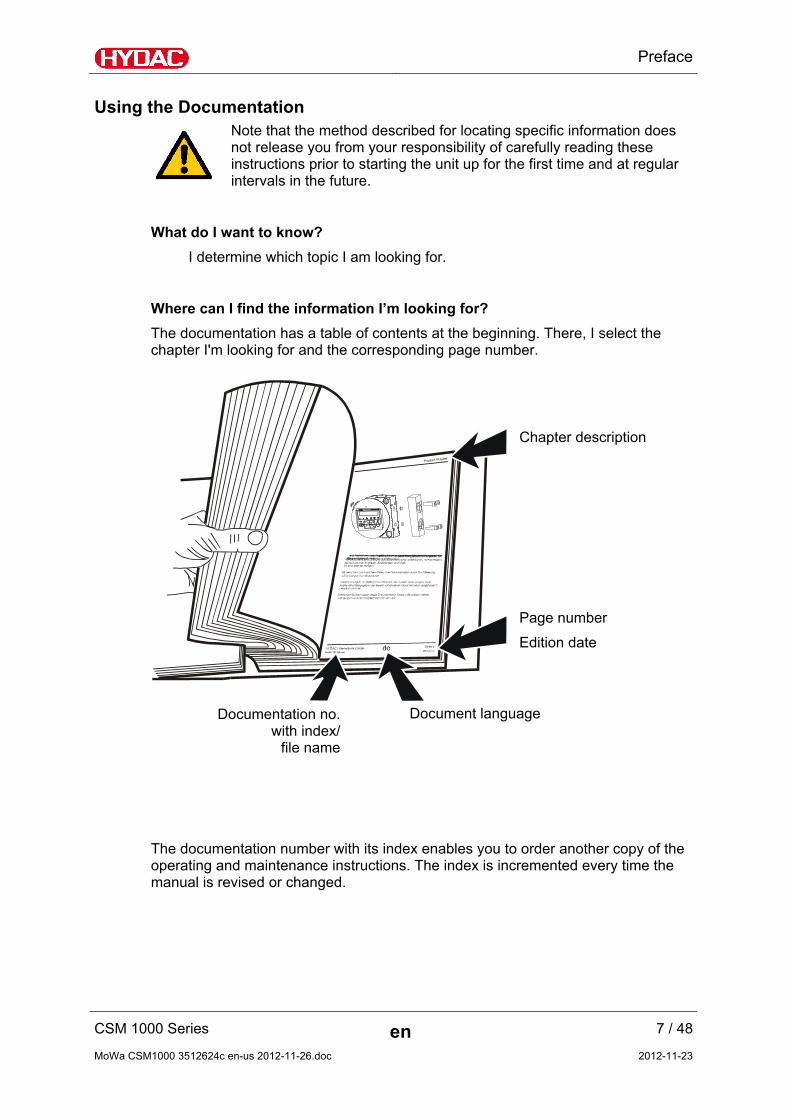
Note that the method described for locating specific information does not release you from your responsibility of carefully reading these instructions prior to starting the unit up for the first time and at regular intervals in the future.
What do I want to know?
I determine which topic I am looking for.
Where can I find the information I’m looking for?
The documentation has a table of contents at the beginning. There, I select the chapter I'm looking for and the corresponding page number.
CSM 1000 Series en 7 / 48
MoWa CSM1000 3512624c en-us 2012-11-26.doc 2012-11-23
Chapter description
Page number
Edition date
Document languageDocumentation no.with index/
file name
The documentation number with its index enables you to order another copy of the operating and maintenance instructions. The index is incremented every time the manual is revised or changed.

Safety Information and Instructions
Safety Information and Instructions
The unit was built according to the statutory provisions valid at the time of delivery and satisfies current safety requirements.
Any residual hazards are indicated by safety information and instructions and are described in the operating instructions.
Observe all safety and warning instructions attached to the unit. They must always be complete and legible.
Do not operate the unit unless all the safety devices are present.
Secure the hazardous areas which may arise between the unit and other equipment.
Maintain the unit inspection intervals prescribed by law.
Document the results in an inspection certificate and keep it until the next inspection.
Hazard symbols
These symbols are listed for all safety information and instructions in these operating instructions which indicate particular hazards to persons, property or the environment.
Observe these instructions and act with particular caution in such cases.
Pass all safety information and instructions on to other users.
General hazard
Danger due to electrical voltage / current
Danger due to operating pressure
Risk of burns due to hot surfaces
Signal words and their meaning in the safety information and
CSM 1000 Series en 8 / 48
MoWa CSM1000 3512624c en-us 2012-11-26.doc 2012-11-23

Safety Information and Instructions
instructions
DANGER DANGER indicates a danger with a high risk and which will lead to death or serious injury if not avoided.
WARNING WARNING indicates a danger with a medium risk and which can lead to death or serious injury if not avoided.
CAUTION CAUTION indicates a danger with a low risk and which can lead to minor injury if not avoided.
NOTE NOTE indicates a danger which will lead to damage to property if not avoided.
CSM 1000 Series en 9 / 48
MoWa CSM1000 3512624c en-us 2012-11-26.doc 2012-11-23

Safety Information and Instructions
Structure of the safety information and instructions
All warning instructions in this manual are highlighted with pictograms and signal words. The pictogram and the signal word indicate the severity of the danger.
Warning instructions listed before an activity are laid out as follows:
SIGNAL WORD
Type and source of danger
Consequence of the danger
HAZARD SYMBOL
► Measures to avert danger
Observe regulatory information
Observe the following regulatory information and guidelines:
Legal and local regulations for accident prevention
Legal and local regulations for environmental protection
Country-specific regulations, organization-specific regulations
CSM 1000 Series en 10 / 48
MoWa CSM1000 3512624c en-us 2012-11-26.doc 2012-11-23

Safety Information and Instructions
Proper/Designated Use
Use the unit only for the application described in the following.
The ContaminationSensor module CSM was developed for the continuous monitoring of particulate contamination in hydraulic systems.
Proper or designated use of the product extends to the following:
observing all instructions contained in the instruction manual.
performing inspection and maintenance work.
Improper use or use deviating from intended use
DANGER
Danger due to unanticipated use of the unit
Bodily injury and damage to property will result when operated improperly.
► Never operate the unit in potentially explosive atmospheres.
► The unit is only to be used with permissible media.
Any use extending beyond or deviating therefrom shall not be considered intended use. HYDAC Filter Systems GmbH will assume no liability for any damage resulting from such use. The user alone, shall assume any and all associated risk
Improper use may result in hazards and/or will damage the unit. Examples of improper use:
o Operation in potentially explosive atmospheres.
o Operation with a non-approved medium.
o Operation under non-approved conditions.
o Operation when the system equipment or safety devices are defective.
o Modifications to the unit made by the user or purchaser.
o Improper monitoring of unit components that are subject to wear and tear.
o Improperly performed repair work
CSM 1000 Series en 11 / 48
MoWa CSM1000 3512624c en-us 2012-11-26.doc 2012-11-23

Safety Information and Instructions
CSM 1000 Series en 12 / 48
MoWa CSM1000 3512624c en-us 2012-11-26.doc 2012-11-23
NOTE
Impermissible operating media
The unit will be destroyed
► The unit is only to be used with mineral oils or mineral oil-based raffinates.
NOTE
Highly contaminated fluid
The pump will become worn out / damaged.
► For long-term operation, pump only fluid with a maximum contamination of ISO 22/20/18

Safety Information and Instructions
CSM 1000 Series en 13 / 48
MoWa CSM1000 3512624c en-us 2012-11-26.doc 2012-11-23
Qualifications of personnel / target group
Persons who work on the machine must be aware of the associated hazards when using the unit.
Operating and specialist personnel must have read and understood the operating instructions, in particular the safety information and instructions, and applicable regulations before beginning work.
The operating instructions and applicable regulations are to kept so they are accessible for operating and specialist personnel.
These operating instructions is intended for:
Operating personnel: such persons have been instructed in machine operation and are aware of potential hazards due to improper use.
Specialist personnel: such persons with corresponding specialist training and several years work experience. They are able to assess and perform the work assigned to them, they are also able to recognize potential hazards.
Activity Person Knowledge
Transport / storage Forwarding agent
Specialist personnel
Proof of knowledge of cargo securing instructions
Safe handling/operation of hoisting and lifting equipment
Hydraulic / electrical installation,
first commissioning,
maintenance,
troubleshooting,
repair,
decommissioning,
disassembly
Specialist personnel
Safe handling/use of tools
Fitting and connection of hydraulic lines and connections
Fitting and connection of electrical lines, electrical machinery, sockets, etc.
Checking the phase sequence
Product-specific knowledge
Operation
Operations control
Specialist personnel
Product-specific knowledge
Knowledge about how to handle operating media.
Knowledge about contamination due to solids and water
Disposal Specialist personnel
Proper and environmentally-friendly disposal of materials and substances
Decontamination of contaminants
Knowledge about reuse

Unpacking the CSM
CSM 1000 Series en 14 / 48
MoWa CSM1000 3512624c en-us 2012-11-26.doc 2012-11-23
Wear suitable clothing
Loose-fitting clothing increases the risk of being caught or being drawn in on rotating parts, and the risk of getting caught on protruding parts. You can be severely injured or killed.
Wear close-fitting clothing.
Do not wear any rings, chains or any other jewelry.
Wear work safety shoes.
Unpacking the CSM
The CSM is function- and leak-tested in the factory and properly packed. The connectors are closed off so that no contamination can enter the unit while it is in transit.
When receiving and unpacking the unit, check it for damage in transit.
Dispose of the packaging material in an environmentally-friendly manner.

Transporting the CSM
Transporting the CSM
Transport the CSM as described below:
Carry the unit by hand using the handle.
Transport the unit in a horizontal position on a pallet.
Support the upper part with a spacer (1). Height ~ 30 mm.
When lashing the equipment, ensure that no protruding components are lashed down.
CSM 1000 Series en 15 / 48
MoWa CSM1000 3512624c en-us 2012-11-26.doc 2012-11-23

Storing the CSM
Storing the CSM
Rinse and drain the unit completely before putting it into extended storage.
Make sure to store the CSM in a clean, dry place.
Store the unit standing up, or lying flat on a pallet.
Support the upper part with a spacer (1). Height ~ 30 mm.
CSM 1000 Series en 16 / 48
MoWa CSM1000 3512624c en-us 2012-11-26.doc 2012-11-23

Checking the Scope of Delivery
Checking the Scope of Delivery
Upon receiving the CSM check it for any damage in transit. Do not put the CSM into operation unless it is in perfect condition. Report any damages in transit to the transport company or the responsible agent immediately. Do not put the unit into operation.
The following items are supplied:
Item Qty. Designation
1 1 Contamination Sensor Modulee, CSM 1000 Series
2 1 Pressure gauge with adapter
- 1
Technical Documentation, const. of: - Operating and Maintenance Instructions CSM 1000 - Operating and Maintenance Instructions CS 1000 Series - Operating and Maintenance Instructions FluMoS light - Operating and Maintenance Instructions AS 1000 (optional)- Calibration certificate of the CS 1000
CSM 1000 Series en 17 / 48
MoWa CSM1000 3512624c en-us 2012-11-26.doc 2012-11-23
CSM Characteristics
CSM 1000 Series en 18 / 48
MoWa CSM1000 3512624c en-us 2012-11-26.doc 2012-11-23
CSM Characteristics
The gear pump sucks the oil to be analyzed and conveys it to the Contamination Sensor, in which the particulate contamination is captured by an optical sensor and analyzed according to particle size classifications and counted.
Any air bubbles contained in the oil may skew the measurement results as they, like particulate contamination, cause the measurement cell to generate signals.
The purpose of the CSM is to suppress air bubbles so that the measurement results are not skewed or only minimally impacted.
Because oil absorbs an increasing quantity of air as the pressure increases (rule of thumb: ~ 8% air per bar), the ContaminationSensor aims to achieve the greatest possible pressure. This is done using a downstream pressure relief valve.
However, pressurized air cannot be immediately dissolved in oil, consequently a path is provided for between the pump and the sensor.
With highly viscous oil and extremely high amounts of air, an air bubble can get stuck directly behind the pump so that it does not rise and flow out through the conduit. The pump is unable to pump against this pressurized air. Through the slightly opened throttle valve located in the conduit between the pump and the ContaminationSensor, the pressure can reduce and the pump starts to pump oil again.
In normal operation, only a small portion of the flow is lost at this throttle valve as the hydraulic resistance of the oil is extremely high. However, air bubbles can easily escape at this position.

CSM components
CSM components
Item Designation
1 Electric motor
2 Gear pump (with or without leakage oil connection depending on order)
3 Test point 1
4 Pressure relief valve
5 Test point 2
6 Counter balance valve
7 Choker valve (optional)
8 ContaminationSensor CS1000 series
9 Suction screen, 400 µm
10 Suction port connection (IN)
11 Return port connection (OUT)
12 AquaSensor 1000 (optional)
13 Leakage oil connection (LEAKAGE) (only with CSM1xxx-2 ...)
CSM 1000 Series en 19 / 48
MoWa CSM1000 3512624c en-us 2012-11-26.doc 2012-11-23

Hydraulic Schematic
Hydraulic Schematic
8
12
5 6 7
3
4
1
11
10
9
2
LEAKAGE
13
Item Designation
1 Electric motor
2 Gear pump (with or without leakage oil connection depending on order)
3 Test point 1
4 Pressure relief valve
5 Test point 2
6 Counter balance valve
7 Choker valve (optional)
8 ContaminationSensor CS1000 series
9 Suction screen, 400 µm
10 Suction port connection (IN)
11 Return port connection (OUT)
12 AquaSensor 1000 (optional)
13 Leakage oil connection (LEAKAGE) (only with CSM1xxx-2 ...)
CSM 1000 Series en 20 / 48
MoWa CSM1000 3512624c en-us 2012-11-26.doc 2012-11-23
Dimensions
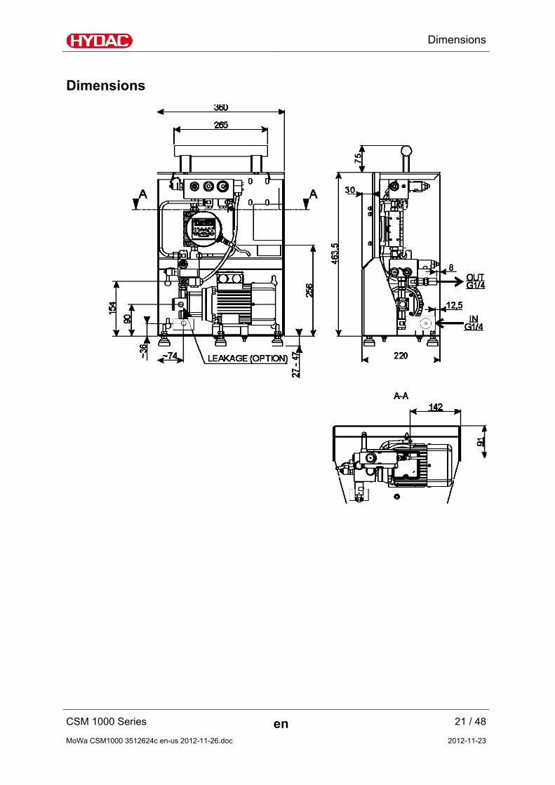
Dimensions
CSM 1000 Series en 21 / 48
MoWa CSM1000 3512624c en-us 2012-11-26.doc 2012-11-23

Hydraulic Connection of the CSM
Drilling template for wall mounting
Hydraulic Connection of the CSM
Hydraulic Connectors
CSM1xxx-1, CSM1xxx-4 CSM1xxx-2
IN = Suction port connection
OUT = Return port connection
LEAKAGE = Leakage oil connection
CSM 1000 Series en 22 / 48
MoWa CSM1000 3512624c en-us 2012-11-26.doc 2012-11-23

Hydraulic Connection of the CSM
CSM 1000 Series en 23 / 48
MoWa CSM1000 3512624c en-us 2012-11-26.doc 2012-11-23
Notes on piping / hosing
In order to keep the pressure differential as low as possible, use as few threaded connections as possible.
The pressure loss in a hydraulic line depends upon:
Flow rate
kinematic viscosity
pipe dimensions
fluid density
The pressure differential can be estimated for hydraulic oils as follows:
Δp ~ 6.8 * L / d4 * Q * V * D Δp = Pressure differential in [bar]
L = pipe length [m]
d = internal pipe diameter [mm]
Q = Flow rate [l/min]
V = kinematics viscosity [mm²/s]
D = Density [kg/dm³] Mineral oil-based hydraulic fluid has a density of ~ 0.9 kg/dm³.
This applies to straight pipe runs and hydraulic oils. Additional threaded connections and pipe bends increase the pressure differential.
Keep the height difference between the pump and the oil level in the tank as minimal as possible.
Hoses must be suitable for suction pressures of at least -0.5 bar.
Constrictions in the connections and lines should be avoided. This could compromise suction output and cause cavitation.
Take note that the nominal size of the connected hoses/piping must be at least as large as the inlet port sizes.
Make sure that no tension or vibrations are carried over to the pump or filter housing when the pipes are connected. Use hoses or expansion joints if necessary.

Hydraulic Connection of the CSM
Suction port connection - IN
NOTE
Overpressure at the suction port connection (IN)
The unit will be destroyed
► Note the maximum pressure on the suction port connection IN for CSM1xxx-1 = -0.4 bar - 0.5 bar for CSM1xxx-2 = -0.4 bar - 120 bar for CSM1xxx-4 = -0.4 bar - 80 bar
Make the suction-side connection with a flexible hose that is resistant to negative pressure or with pipelines. The nominal size of the connecting lines must be at least as large as the cross-section of the unit in order to prevent excessively high pressure loss.
Suction connection to the tank must be done in a manner so that it is always below the oil level.
NOTE
Severe contamination
The unit will be damaged
► Do not prime directly at the bottom of the tank
► Do not prime in the sump
► Never prime without a built-in suction screen
The greatest contamination is found on the bottom of the tank. All impurities and other particles are deposited on the bottom of the tank.
Make the suction-side connection with a flexible hose that is resistant to negative pressure or with pipelines. The nominal size of the connecting lines must be at least as large as the cross-section of the unit in order to prevent excessively high pressure loss.
Suction connection to the tank must be done in a manner so that it is always below the oil level.
CSM 1000 Series en 24 / 48
MoWa CSM1000 3512624c en-us 2012-11-26.doc 2012-11-23

Hydraulic Connection of the CSM
CSM 1000 Series en 25 / 48
MoWa CSM1000 3512624c en-us 2012-11-26.doc 2012-11-23
Return port connection - OUT
NOTE
Return port connection (OUT) closed
The unit will be destroyed
► Make sure that the return port is always open
Leakage oil connection - LEAKAGE (only with CSM1xxx-2 ...)
NOTE
Leakage oil connection (LEAKAGE) closed
The unit will be destroyed
► Make sure that the leakage oil connection is always open.
► Note the maximum pressure of 0.5 bar at the leakage oil connection

Hydraulic Connection of the CSM
CSM 1000 Series en 26 / 48
MoWa CSM1000 3512624c en-us 2012-11-26.doc 2012-11-23
Magnetic coupling (only CSM 1xxx-4…)
The CSM1xx0-4… is equipped with a magnetic coupling between the electric motor and the pump.
NOTE
Slipping magnetic coupling
Fluid is no longer being pumped, the magnetic coupling starts to make noises and is destroyed.
► A) Switch the unit off.
► B) Check the pump temperature. Switch the unit on only after the pump has cooled down to below 50°C.
► C) Check if the return line (OUT) is open.
► D) Check the pressure setting on the pressure gauge. Correct the pressure setting if necessary.
Electrical Connection of the CSM
Electrical Connection of the CSM
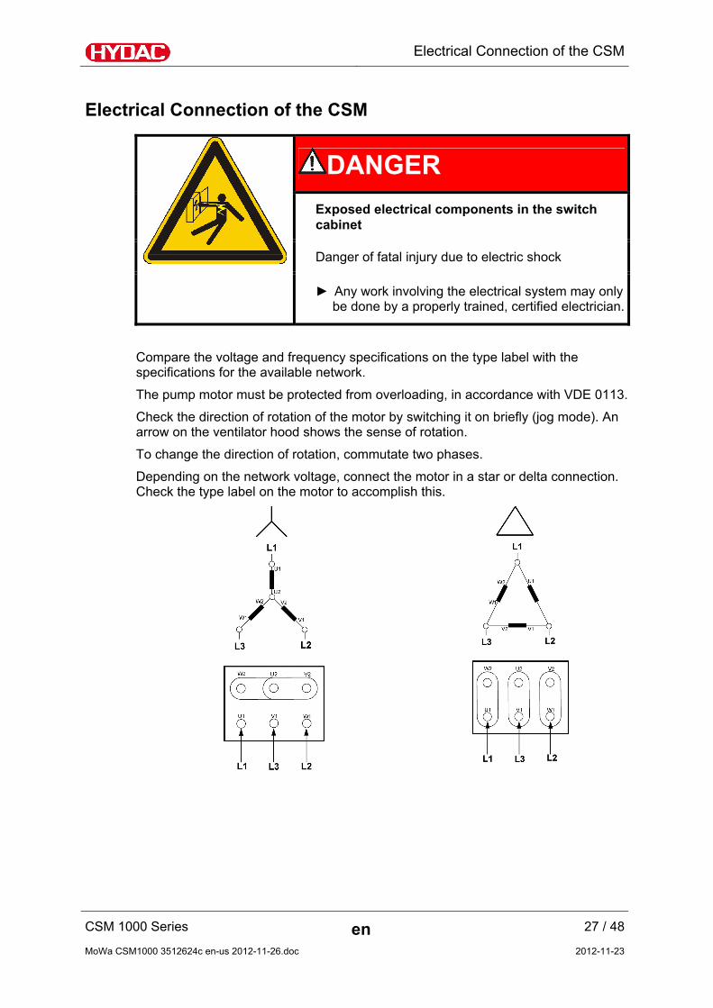
DANGER
Exposed electrical components in the switch cabinet
Danger of fatal injury due to electric shock
► Any work involving the electrical system may only be done by a properly trained, certified electrician.
Compare the voltage and frequency specifications on the type label with the specifications for the available network.
The pump motor must be protected from overloading, in accordance with VDE 0113.
Check the direction of rotation of the motor by switching it on briefly (jog mode). An arrow on the ventilator hood shows the sense of rotation.
To change the direction of rotation, commutate two phases.
Depending on the network voltage, connect the motor in a star or delta connection. Check the type label on the motor to accomplish this.
CSM 1000 Series en 27 / 48
MoWa CSM1000 3512624c en-us 2012-11-26.doc 2012-11-23

Electrical Connection of the CSM
CSM 1000 Series en 28 / 48
MoWa CSM1000 3512624c en-us 2012-11-26.doc 2012-11-23
Electrical connection of the ContaminationSensor CS1000
For more information, refer to the ContaminationSensor operating and maintenance instructions included.
Electrical connection of the AquaSensor AS1000
For more information, refer to the AquaSensor operating and maintenance instructions included.

Starting up the CSM
Starting up the CSM
You must adjust the counter balance valve (B) once the CSM has been connected hydraulically to the entire system with IN/OUT, and with LEAKAGE if applicable, and the electrical connection has been completed.
The counter balance valve (B) and the throttle valve (A) are completely open at the time the unit is shipped.
Adjusting the counter balance valve
Required tools and measuring instruments
Combination wrench, size 22 mm
Combination wrench, size 13 mm
Allen wrench, size 4 mm
Pressure gauge 0-60 bars, included adapter
(comes standard with the CSM)
Set the counter balance valve (B) in accordance with the following steps:
CSM 1000 Series en 29 / 48
MoWa CSM1000 3512624c en-us 2012-11-26.doc 2012-11-23
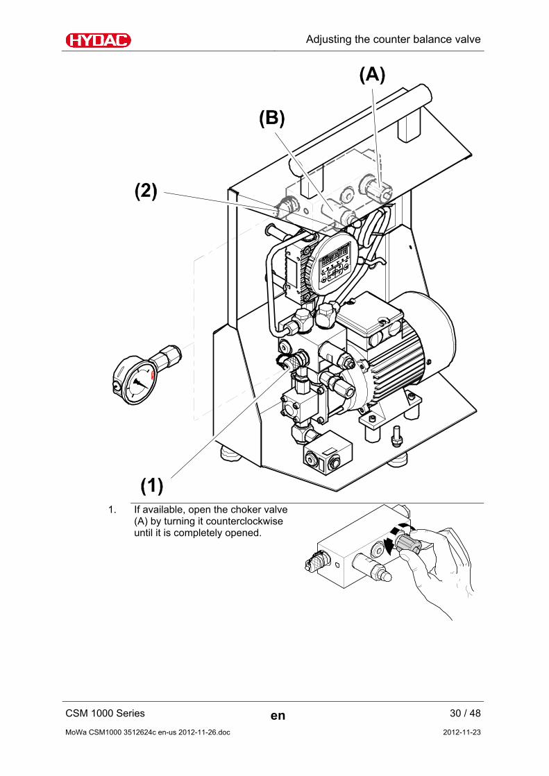
Adjusting the counter balance valve
1. If available, open the choker valve (A) by turning it counterclockwise until it is completely opened.
CSM 1000 Series en 30 / 48
MoWa CSM1000 3512624c en-us 2012-11-26.doc 2012-11-23

Adjusting the counter balance valve
2. Unscrew the manometer onto the test point (1).
3. Switch the CSM on.
4. Check the suction intake behavior of the pump and the oil flow.
5. If a uniform volume flow can be detected on the basis of the sound the pump is making and/or at the outlet side (OUT), then rotate the vacuum gauge (A) in clockwise direction until it is completely closed.
6. The pressure gauge at the test point
(1) shows the pressure at the inlet of the ContaminationSensor CS1000 (max. 60 bar).
7. Unscrew the head-nut from the
counter balance valve (B).
CSM 1000 Series en 31 / 48
MoWa CSM1000 3512624c en-us 2012-11-26.doc 2012-11-23

Adjusting the counter balance valve
8. Release the counter-nut on the counter balance valve (B).
9. Set the pressure range for a
maximum operating medium viscosity to between 25 and 40 bar by using a size 4 Allen wrench to rotate the set screw on the counter balance valve (B).
Note that a differential in comparison with the pressure measured in Step 6 of a least 10 bar more is to be recommended.
10. Tighten the lock nut. Make sure that
the setting of the counter balance valve (B) is not changed in the process.
CSM 1000 Series en 32 / 48
MoWa CSM1000 3512624c en-us 2012-11-26.doc 2012-11-23

Adjusting the counter balance valve
11. Screw the head-nut onto the counter balance valve (B) and tighten it firmly.
12. Unscrew the manometer from the
test point (1).
13. The CSM is now ready for use.
CSM 1000 Series en 33 / 48
MoWa CSM1000 3512624c en-us 2012-11-26.doc 2012-11-23

Performing Maintenance
Performing Maintenance
WARNING
Operating pressure
Danger of bodily injury
► The hydraulic system must be depressurized before performing any work on the hydraulic system.
The prescribed adjustment, maintenance/servicing and inspection work is to be conducted in accordance with the respective schedules.
The unit is to be disconnected from the power supply and protected against being inadvertently switched back on when performing any maintenance, servicing, inspection or repair work.
Once maintenance work is complete, check that the safety devices are still working properly. Any screwed fittings which have been undone/removed are to be checked to see that they have been properly resecured.
24 hrs. or
daily
500 hrs. or
monthly
3000 hrs. or
twice per year
Check for leaks X
Visual check of electrical equipment X
Clean the suction strainer. X
CSM 1000 Series en 34 / 48
MoWa CSM1000 3512624c en-us 2012-11-26.doc 2012-11-23
Performing Maintenance
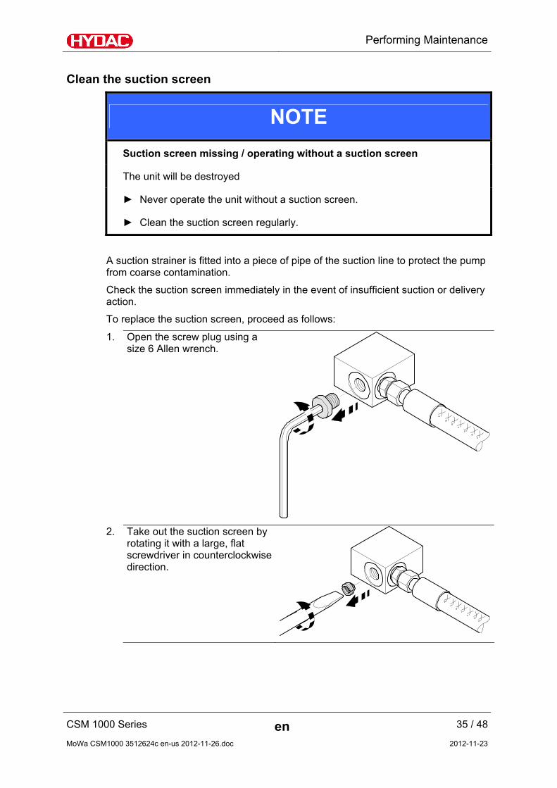
Clean the suction screen
NOTE
Suction screen missing / operating without a suction screen
The unit will be destroyed
► Never operate the unit without a suction screen.
► Clean the suction screen regularly.
A suction strainer is fitted into a piece of pipe of the suction line to protect the pump from coarse contamination.
Check the suction screen immediately in the event of insufficient suction or delivery action.
To replace the suction screen, proceed as follows:
1. Open the screw plug using a size 6 Allen wrench.
2. Take out the suction screen by rotating it with a large, flat screwdriver in counterclockwise direction.
CSM 1000 Series en 35 / 48
MoWa CSM1000 3512624c en-us 2012-11-26.doc 2012-11-23

Performing Maintenance
3. Clean the suction screen by washing it out and then blowing it out with compressed air.
4. Rotate the suction screen in
clockwise direction into the housing with a large, flat screwdriver.
5. Screw in the screw plug by hand and tighten it with 12 Nm.
CSM 1000 Series en 36 / 48
MoWa CSM1000 3512624c en-us 2012-11-26.doc 2012-11-23

Disposing of the CSM
CSM 1000 Series en 37 / 48
MoWa CSM1000 3512624c en-us 2012-11-26.doc 2012-11-23
Disposing of the CSM
After dismantling the unit and separating the various materials, dispose of the unit in an environmentally-friendly manner.
Errors and Troubleshooting
Error Cause(s) Remedy
No flow The pump is conveying in the wrong direction.
Check the sense of rotation of the motor and, if necessary, reverse the phases.
Shut-off device outside of the CSM in the suction or pressure line is closed.
Open all the locking features in the suction and pressure lines.
Suction strainer is clogged. Clean the suction strainer. See page 35.
Only CSM1xxx-1 / -2:
The coupling between the motor and the pump is loose or faulty.
Contact HYDAC.
Only CSM1xxx-4:
The magnetic coupling is disengaged and is slipping. Loud noise emissions.
Switch the pump off. Allow the unit to cool down. Switch the unit on again.
Contact HYDAC.
No function Not connected to power supply.
Check the electrical connection; plug, cable and socket.
For CS1000 error messages, refer to the corresponding chapter in your CS1000 operating and maintenance manual.

Spare parts
Spare parts
Make sure to indicate the entire unit designation and the serial number in accordance with the type label when ordering spare parts.
CSM 1000 Series en 38 / 48
MoWa CSM1000 3512624c en-us 2012-11-26.doc 2012-11-23

Spare parts
CSM 1000 Series en 39 / 48
MoWa CSM1000 3512624c en-us 2012-11-26.doc 2012-11-23

Spare parts
Item Description Qty Part no.
20 Handle 1 6026672
60 Part of joint 3 3135672
100 Strainer element 1 3152786
140 Motor pump assembly 1 *
150 Rubber buffer 4 606841
240 Threaded coupling 2 606304
250 Pressure relief valve 1 *
270 ContaminationSensor CS1000 1 *
320 Pressure relief valve 1 557654
330 Throttle valve 1 705426
340 AquaSensor AS 1 *
420 Type label 1 3137999
430 "Circuit diagram" sign 1 3265699
435 "STRAINER" sign 1 3490464
440 "IN" sign 1 3130347
445 "LEAKAGE" sign 1 3264852
450 "OUT" sign 1 3130551
455 "DO NOT BLOCK" sign 1 3259154
470 Connection for pressure gauge 1 6003824
480 Pressure gauge 1 606764
700 "Direction of rotation" warning sign 1 3529226
CSM 1000 Series en 40 / 48
MoWa CSM1000 3512624c en-us 2012-11-26.doc 2012-11-23

Accessories
CSM 1000 Series en 41 / 48
MoWa CSM1000 3512624c en-us 2012-11-26.doc 2012-11-23
Item Description Qty Part no.
- Installation and Maintenance Instructions 1 3512624
*) Upon request
Accessories
The CSM accessories are listed in the following.
Plugs
Part no.
Connector female with screw clamp ZBE 08 6006786
Connector female with screw clamp,
shielded ZBE 44 3281243
Connection cable, shielded
Connector female ↔ Cable ending open Length Part no.
↔ + shield 2 m ZBE 42S-02 3281220
↔ + shield 5 m ZBE 42S-05 3281239
↔ + shield 2 m ZBE 08S-02 6019455
↔ + shield 5 m ZBE 08S-05 6019456
↔ + shield 10 m ZBE 08S-10 6023102
↔ + shield 30 m ZBE 08S-30 6035063
Connection cable
Connector female ↔ Cable ending open Length Part no.
↔ 2 m ZBE 0P-02 6052697
↔ 5 m ZBE 0P-05 6052698
↔ 2 m ZBE 08-02 6006792
↔ 5 m ZBE 08-05 6006791

Customer service
Connection cable
Connector female ↔ Connector male Length Part no.
↔ 5 m ZBE 43-05 3281240
↔ 2 m ZBE 30-02 6040851
↔ 3 m ZBE 30-03 6053924
↔ 5 m ZBE 30-05 6040852
Customer service
HYDAC SERVICE GMBH Friedrichsthaler Strasse 15a, Werk 13 66540 Neunkirchen-Heinitz
Germany
Telephone: ++49 (0)681 509 883
Fax: ++49 (0)681 509 324
E-mail: [email protected]
CSM 1000 Series en 42 / 48
MoWa CSM1000 3512624c en-us 2012-11-26.doc 2012-11-23

Technical data
CSM 1000 Series en 43 / 48
MoWa CSM1000 3512624c en-us 2012-11-26.doc 2012-11-23
Technical data
General data
Medium temperature 0 … 70°C / 32 … 158°F
Ambient temperature 0 … 40°C / 32 … 104°F
Storage temperature -40°C … 80°C / -40°F … 176°F
Relative humidity maximum 90%, non-condensing
Weight ~ 18 kg
Hydraulic data
CSM1xxx-1 - 0.4 bar … 0.5 bar
CSM1xxx-2 - 0.4 bar … 120 bar Permissible pressure at suction port connection (IN)
CSM1xxx-4 - 0.4 bar … 80 bar
Permissible pressure at leakage oil connection (LEAKAGE) CSM1xxx-2 0.5 bar maximum
Permissible pressure at return port connection (OUT)
CSM1xxx-1 CSM1xxx-2 CSM1xxx-4
5 bar maximum
Pump types Gear pump
Maximal suction height 500 mm
Sealing material NBR / FKM*
Suction port connection (IN) G ¼“
Return port connection (OUT) G ¼“
Leakage oil connection (LEAKAGE) G ¼“
CSM1xxx-1 CSM1xxx-2 10 … 3000 mm²/s Permissible operating viscosity
range CSM1xxx-4 10 … 1000 mm²/s
CSM1xxx-1 CSM1xxx-2 10 … 1000 mm²/s Permissible viscosity range for
the measurement operation CSM1xxx-4 10 … 800 mm²/s

Technical data
Hydraulic data
Total flow rate 50 Hz 60 Hz
CSM1xxx-1 ~ 90 ml/min ~ 110 ml/min
CSM1xxx-2 ~ 180 ml/min ~ 220 ml/min
CSM1xxx-4 ~ 230 ml/min ~ 260 ml/min
*) According to model code
Electrical data CSM1xxx-x-x-W/N/X60/O60
Voltage frequency 50 Hz 60 Hz
Voltage (delta connection) 230 V, 50 Hz, 3 Ph 265 V, 60 Hz, 3 Ph
Voltage (Star (Y-) connection) 400 V, 50 Hz, 3 Ph 460 V, 60 Hz, 3 Ph
Current consumption 1.23 A / 0.71 A 1.18 A / 0.68 A
Nominal power 0.18 kW 0.21 kW
Continuous duty rating 100% 100%
Rotation speed 1425 rpm 1710 rpm
IP class IP55 IP55
Insulation class F F
Electrical data CSM1xxx--x-x-N/AB/N60/AB60
Voltage frequency 50 Hz 60 Hz
Voltage (delta connection) 400 V, 50 Hz, 3 Ph 400 V, 60 Hz, 3 Ph
Voltage (Star (Y-) connection) 690 V, 50 Hz, 3 Ph 690 V, 60 Hz, 3 Ph
Current consumption 0.71 A / 0.41 A 0.57 A / 0.33 A
Nominal power 0.18 kW 0.18 kW
Continuous duty rating 100% 100%
Rotation speed 1425 rpm 1755 rpm
IP class IP55 IP55
Insulation class F F For other electrical versions, obtain the respective data from the type label on the electric motor.
CSM 1000 Series en 44 / 48
MoWa CSM1000 3512624c en-us 2012-11-26.doc 2012-11-23

Model Code
CSM 1000 Series en 45 / 48
Model Code
CSM 1 2 2 0 - 1 - 1 W/N/X60/O60 AS
Type CSM Version 1 = 4 particle size channels Contamination code 2 = ISO4406:1999, SAE AS 4059(D) /
>4 µm(c) >6 µm(c), 14 µm(c) >21 µm(c)
3 = ISO4406:1987, NAS1638 / >2 µm >5 µm >15 µm > 25 µm ISO4406:1999, SAE AS 4059(D) / >4 µm(c) >6 µm(c), 14 µm(c) >21 µm(c), can be switched
Option 1 = without display 2 = with display Fluids 0 = based on mineral oil Hydraulic Version 1 = Gear pump, standard
2 = Gear pump, inlet pressure-stable, up to a maximum of 120 bar, with oil leakage pipe
4 = Gear pump, inlet pressure-stable, up to a maximum of 80 bar, without oil leakage pipe
Electrical Outlet 1 = 4 … 20 mA analog outlet 2 = 0 … 10 V analog outlet Supply voltage W/N/X60/O60 = 230 V, 50 Hz, 3 Ph / 265 V, 60 Hz, 3 Ph
400 V, 50 Hz, 3 Ph / 460 V 60 Hz, 3 Ph N/AB/N60/AB60 = 400 V, 50 Hz, 3 Ph / 400 V 60 Hz, 3 Ph
690 V, 50 Hz, 3 Ph / 690 V 60 Hz, 3 Ph Other voltages on request
Supplementary details Without = Series AS = with AquaSensor AS1000 HL = with HYDACLab
MoWa CSM1000 3512624c en-us 2012-11-26.doc 2012-11-23

Notes
Notes

HYDAC FILTER SYSTEMS GMBH Industriegebiet Postfach 1251 66280 Sulzbach/Saar 66273 Sulzbach/Saar Germany Germany Phone: +49 (0) 6897 509 01 Central Fax: +49 (0) 6897 509 846 (Technical Department) Fax: +49 (0) 6897 509 577 (Sales Department) Internet: www.hydac.com E-Mail: [email protected]