Embed Size (px)
Citation preview
EUROMET-CCT.WG5 meeting Paris, Sept 2001 1
CSIROAustralia
Calibration Uncertainties in Infra-Red Radiation thermometry
Joint EUROMET CCT-WG5 meeting
BNM-INM, Paris, September 2001
By Dr Mark Ballico,
National Measurement Laboratory, Australia
EUROMET-CCT.WG5 meeting Paris, Sept 2001 2
CSIROAustralia
Outline
• Calibration Schemes: only consider pyrometer calibration here, but the same terms appear for calibration of a clients’ BB.
• Definition of major uncertainty terms
– My view: It is essential to agree on a set of terms for the uncertainties, so that we understand each other, and don’t double count terms.
• Some experimental techniques for measuring major terms
– The best way to define these terms is operationally, i.e. define them by demonstrating how they are measured.
– My view: Major uncertainty terms should be experimentally determined by the laboratory: i.e manufacturers specs not enough.
• A few examples– n.b. examples give U95 or k=2 estimates
– The examples are typical only: not best / recommended
• Summary
EUROMET-CCT.WG5 meeting Paris, Sept 2001 3
CSIROAustralia
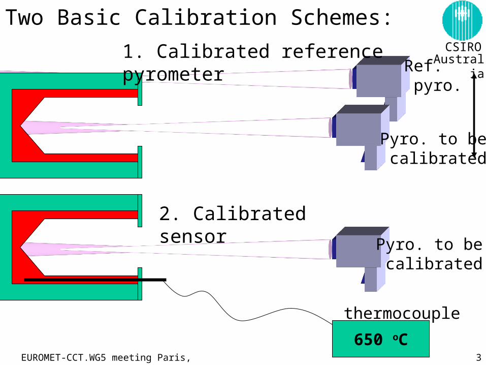
650 oC
thermocouple
Pyro. to be calibrated
Ref. pyro.
2. Calibrated sensor
1. Calibrated reference pyrometer
Pyro. to be calibrated
Two Basic Calibration Schemes:
EUROMET-CCT.WG5 meeting Paris, Sept 2001 4
CSIROAustralia
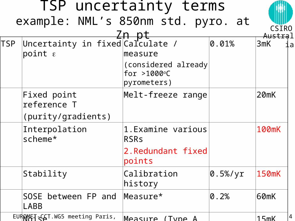
TSP uncertainty termsexample: NML’s 850nm std. pyro. at Zn pt
TSP Uncertainty in fixed point Calculate / measure(considered already for >1000oC pyrometers)
0.01% 3mK
Fixed point reference T
(purity/gradients)
Melt-freeze range 20mK
Interpolation scheme* 1.Examine various RSRs
2.Redundant fixed points
100mK
Stability Calibration history 0.5%/yr 150mK
SOSE between FP and LABB Measure* 0.2% 60mK
Noise Measure (Type A or B) 15mK
DVM DVM calib report U report 0.5V+4ppm 3mK
DVM reported max. error report 4ppm <1mK
2 year drift Manuf. spec. 5V+14ppm 30mK
EUROMET-CCT.WG5 meeting Paris, Sept 2001 5
CSIROAustralia
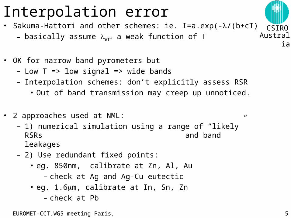
Interpolation error• Sakuma-Hattori and other schemes: ie. I=a.exp(-/(b+cT)
– basically assume eff a weak function of T
• OK for narrow band pyrometers but
– Low T => low signal => wide bands
– Interpolation schemes: don’t explicitly assess RSR
• Out of band transmission may creep up unnoticed.
• 2 approaches used at NML:
– 1) numerical simulation using a range of “likely” RSRs and band leakages
– 2) Use redundant fixed points:
• eg. 850nm, calibrate at Zn, Al, Au
– check at Ag and Ag-Cu eutectic
• eg. 1.6m, calibrate at In, Sn, Zn
– check at Pb
EUROMET-CCT.WG5 meeting Paris, Sept 2001 6
CSIROAustralia
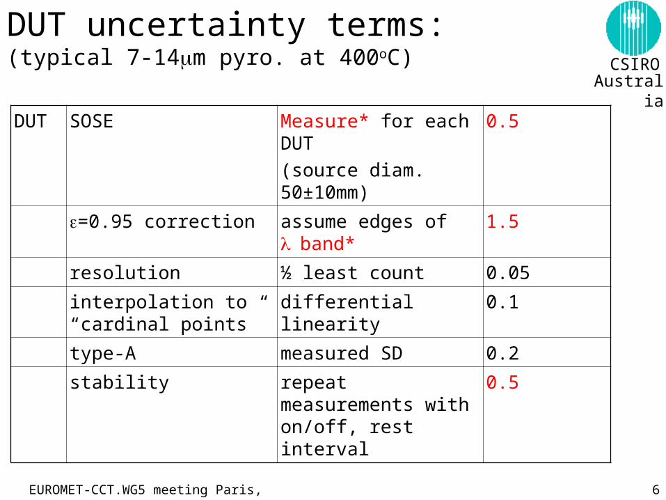
DUT uncertainty terms: (typical 7-14m pyro. at 400oC)
DUT SOSE Measure* for each DUT
(source diam. 50±10mm)
0.5
=0.95 correction assume edges of band* 1.5
resolution ½ least count 0.05
interpolation to “cardinal points”
differential linearity 0.1
type-A measured SD 0.2
stability repeat measurements with on/off, rest interval
0.5
EUROMET-CCT.WG5 meeting Paris, Sept 2001 7
CSIROAustralia
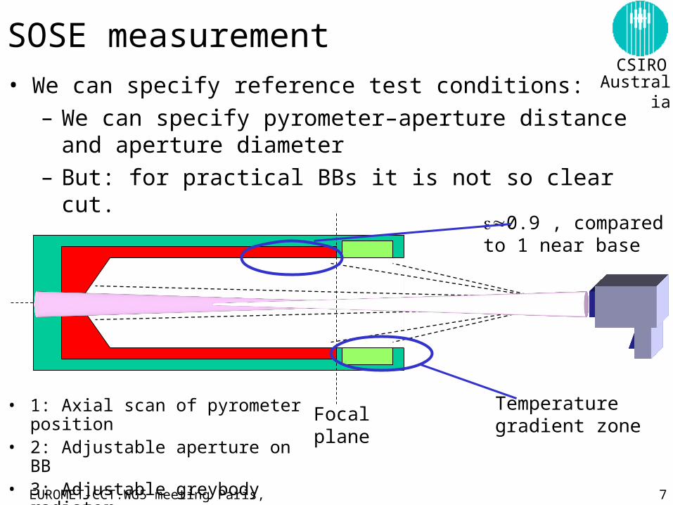
SOSE measurement• We can specify reference test conditions:
– We can specify pyrometer–aperture distance and aperture diameter
– But: for practical BBs it is not so clear cut.
• 1: Axial scan of pyrometer position• 2: Adjustable aperture on BB• 3: Adjustable greybody radiator
Focalplane
0.9 , compared to 1 near base
Temperaturegradient zone
EUROMET-CCT.WG5 meeting Paris, Sept 2001 8
CSIROAustralia
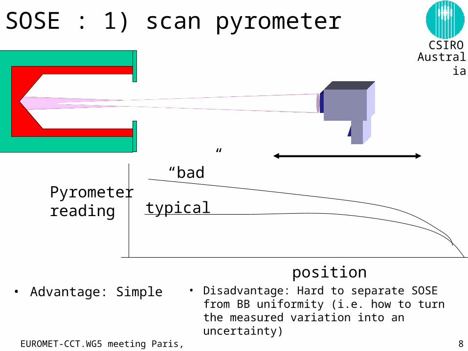
SOSE : 1) scan pyrometer
Pyrometerreading
position
typical
“bad”
• Advantage: Simple • Disadvantage: Hard to separate SOSE from BB uniformity (i.e. how to turn the measured variation into an uncertainty)
EUROMET-CCT.WG5 meeting Paris, Sept 2001 9
CSIROAustralia
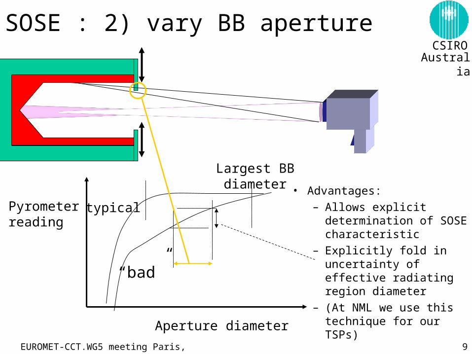
SOSE : 2) vary BB aperture
Pyrometerreading
Aperture diameter
Largest BB diameter
typical
“bad”
• Advantages:
– Allows explicit determination of SOSE characteristic
– Explicitly fold in uncertainty of effective radiating region diameter
– (At NML we use this technique for our TSPs)
EUROMET-CCT.WG5 meeting Paris, Sept 2001 10
CSIROAustralia
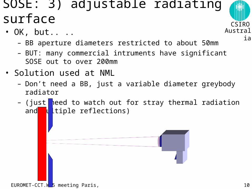
SOSE: 3) adjustable radiating surface
• OK, but.. ..– BB aperture diameters restricted to about 50mm
– BUT: many commercial intruments have significant SOSE out to over 200mm
• Solution used at NML– Don’t need a BB, just a variable diameter greybody radiator
– (just need to watch out for stray thermal radiation and multiple reflections)
EUROMET-CCT.WG5 meeting Paris, Sept 2001 11
CSIROAustralia
Uncertainty
0
1
2
3
4
-100 0 100 200 300 400 500 600 700 800 900
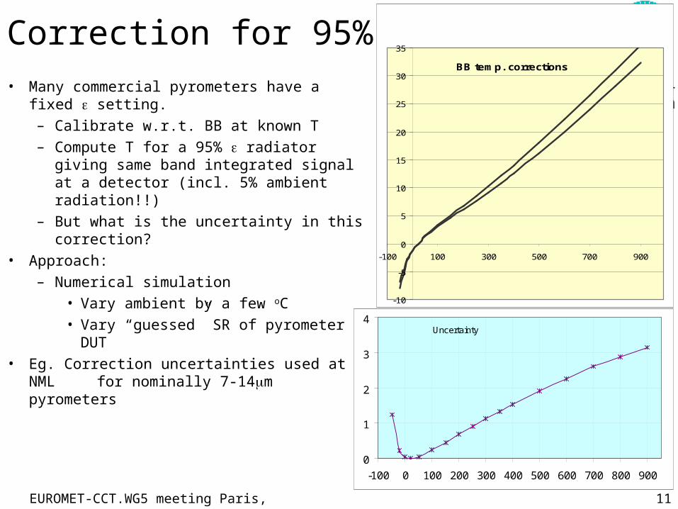
Correction for 95% • Many commercial pyrometers have a fixed
setting.
– Calibrate w.r.t. BB at known T
– Compute T for a 95% radiator giving same band integrated signal at a detector (incl. 5% ambient radiation!!)
– But what is the uncertainty in this correction?
• Approach:
– Numerical simulation
• Vary ambient by a few oC
• Vary “guessed” SR of pyrometer DUT
• Eg. Correction uncertainties used at NML for nominally 7-14m
pyrometers
BB temp. corrections
-10
-5
0
5
10
15
20
25
30
35
-100 100 300 500 700 900
EUROMET-CCT.WG5 meeting Paris, Sept 2001 12
CSIROAustralia
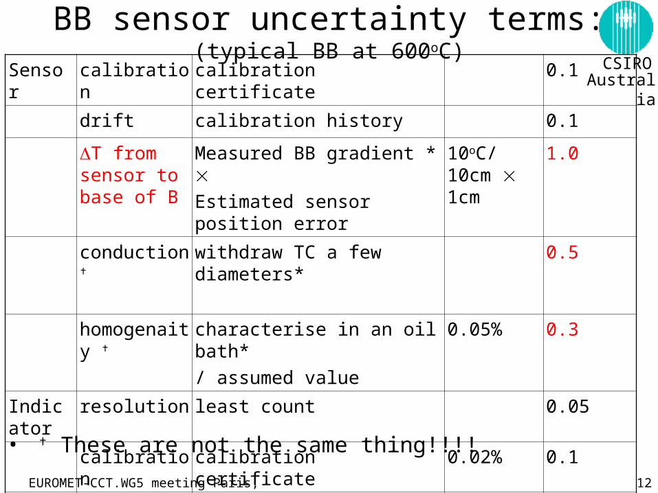
BB sensor uncertainty terms: (typical BB at 600oC)
Sensor calibration calibration certificate 0.1
drift calibration history 0.1
T from sensor to base of B
Measured BB gradient * Estimated sensor position error
10oC/ 10cm 1cm
1.0
conduction withdraw TC a few diameters* 0.5
homogenaity characterise in an oil bath*
/ assumed value
0.05% 0.3
Indicator
resolution least count 0.05
calibration calibration certificate 0.02% 0.1
stability use manufacturers max. drift rate 20ppm/yr 0.01
type-A SD of repeated measurements 0.1
• These are not the same thing!!!!
EUROMET-CCT.WG5 meeting Paris, Sept 2001 13
CSIROAustralia
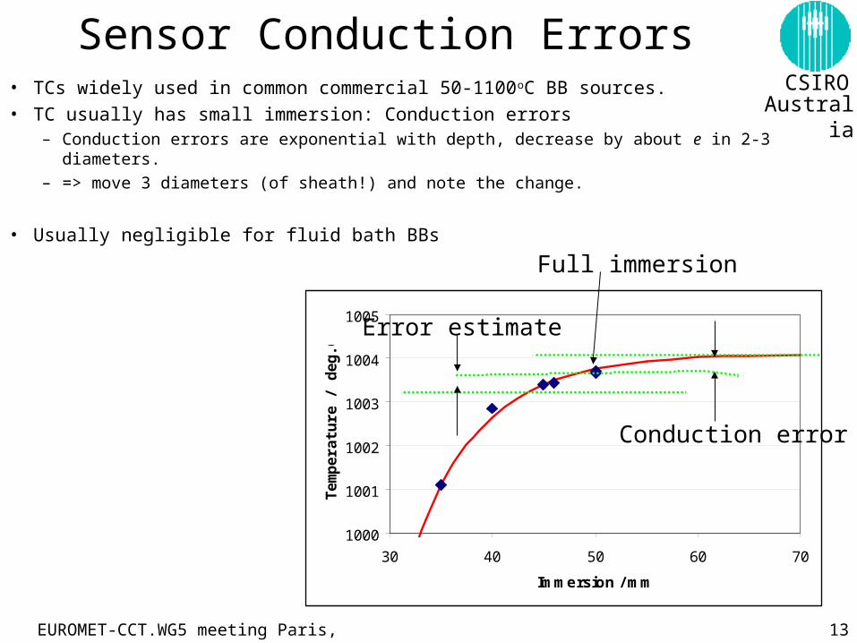
Sensor Conduction Errors• TCs widely used in common commercial 50-1100oC BB sources.
• TC usually has small immersion: Conduction errors– Conduction errors are exponential with depth, decrease by about e in 2-3 diameters.– => move 3 diameters (of sheath!) and note the change.
• Usually negligible for fluid bath BBs
1000
1001
1002
1003
1004
1005
30 40 50 60 70
Immersion / mm
Te
mp
era
ture
/ d
eg
.C
Full immersion
Error estimate
Conduction error
EUROMET-CCT.WG5 meeting Paris, Sept 2001 14
CSIROAustralia
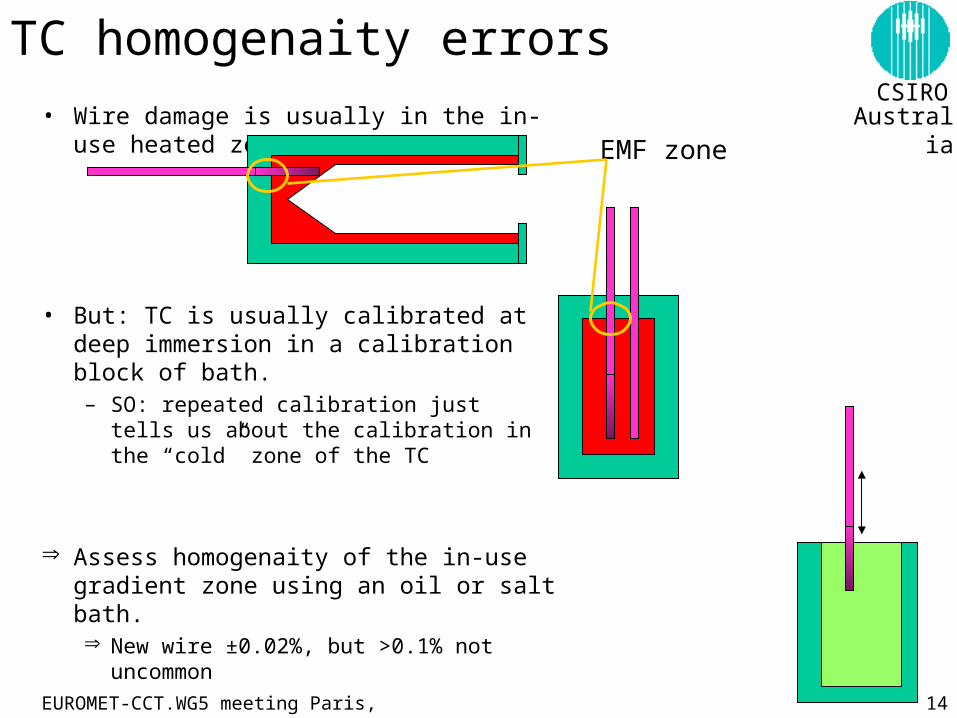
TC homogenaity errors
• Wire damage is usually in the in-use heated zone
• But: TC is usually calibrated at deep immersion in a calibration block of bath.– SO: repeated calibration just tells us about
the calibration in the “cold” zone of the TC
Assess homogenaity of the in-use gradient zone using an oil or salt bath. New wire ±0.02%, but >0.1% not uncommon
EMF zone
EUROMET-CCT.WG5 meeting Paris, Sept 2001 15
CSIROAustralia
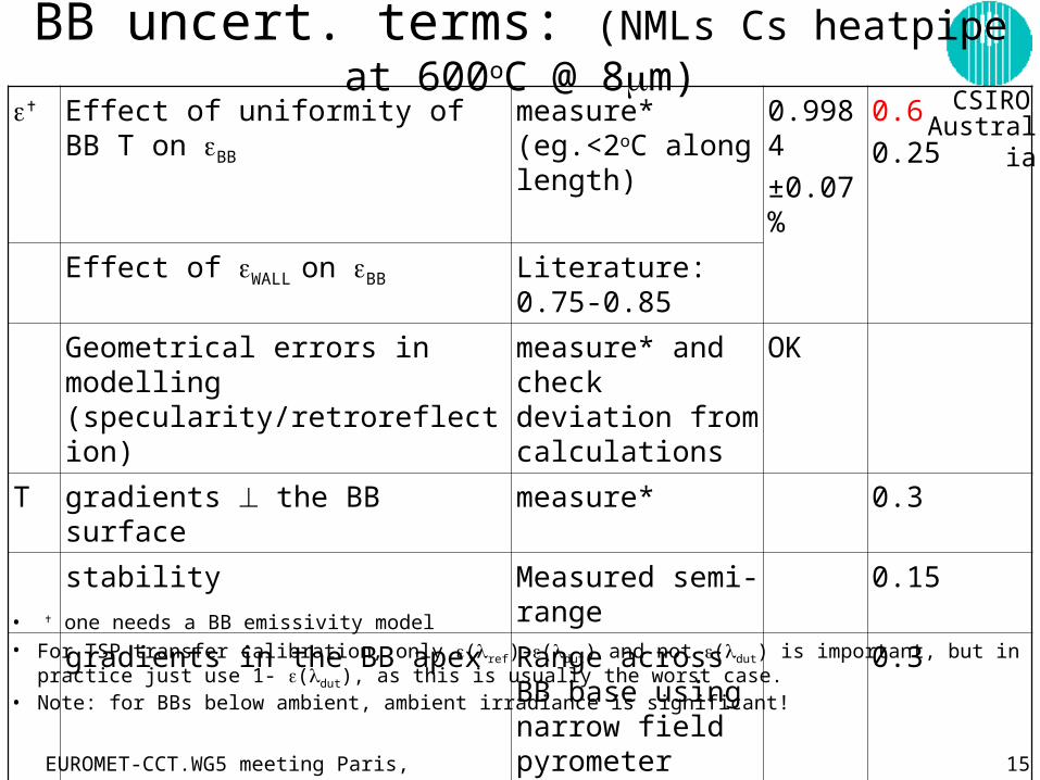
BB uncert. terms: (NMLs Cs heatpipe at 600oC @ 8m)
Effect of uniformity of BB T on BB measure* (eg.<2oC along length)
0.9984
±0.07%
0.6
0.25
Effect of WALL on BB Literature: 0.75-0.85
Geometrical errors in modelling (specularity/retroreflection)
measure* and check deviation from calculations
OK
T gradients the BB surface measure* 0.3
stability Measured semi-range
0.15
gradients in the BB apex Range across BB base using narrow field pyrometer
0.3
• one needs a BB emissivity model• For TSP transfer calibration, only (ref)-(dut) and not (dut) is important, but in practice just use 1- (dut), as this
is usually the worst case.• Note: for BBs below ambient, ambient irradiance is significant!
EUROMET-CCT.WG5 meeting Paris, Sept 2001 16
CSIROAustralia
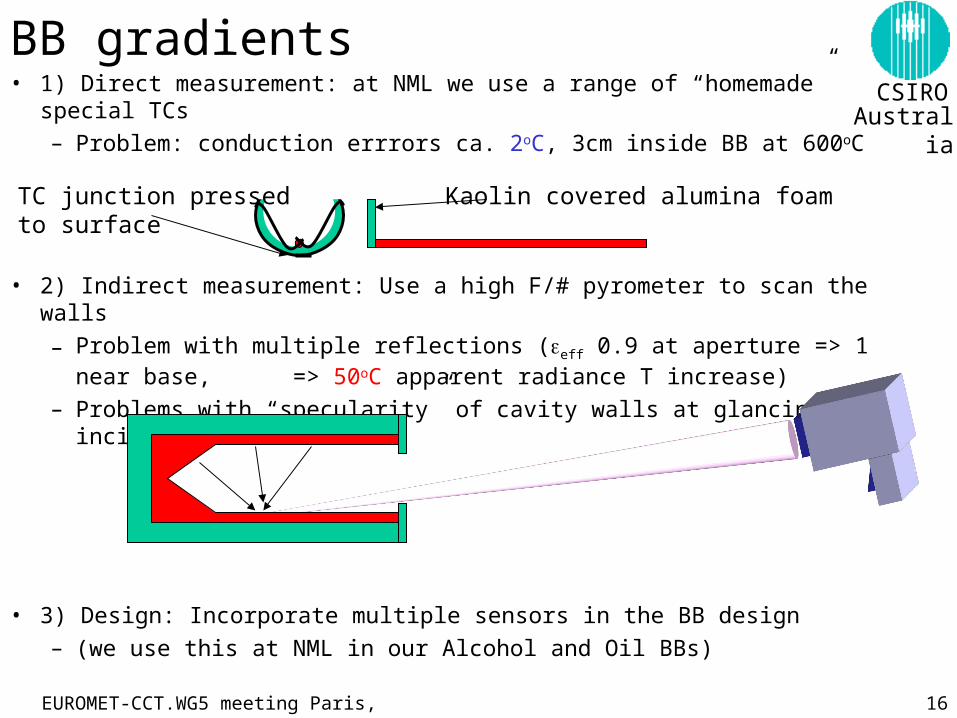
BB gradients• 1) Direct measurement: at NML we use a range of “homemade” special TCs
– Problem: conduction errrors ca. 2oC, 3cm inside BB at 600oC
• 2) Indirect measurement: Use a high F/# pyrometer to scan the walls
– Problem with multiple reflections (eff 0.9 at aperture => 1 near base, => 50oC apparent radiance T increase)
– Problems with “specularity” of cavity walls at glancing incidence
• 3) Design: Incorporate multiple sensors in the BB design
– (we use this at NML in our Alcohol and Oil BBs)
Kaolin covered alumina foamTC junction pressedto surface
EUROMET-CCT.WG5 meeting Paris, Sept 2001 17
CSIROAustralia
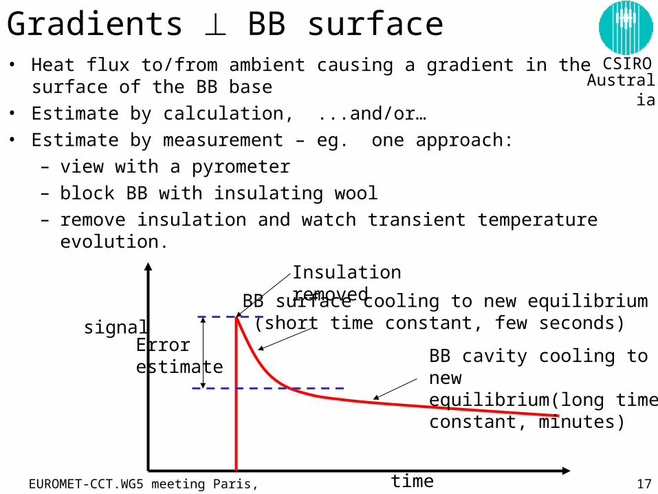
Gradients BB surface • Heat flux to/from ambient causing a gradient in the surface of the BB base
• Estimate by calculation, ...and/or…
• Estimate by measurement – eg. one approach:
– view with a pyrometer
– block BB with insulating wool
– remove insulation and watch transient temperature evolution.
time
signal
Insulation removed
BB surface cooling to new equilibrium (short time constant, few seconds)
BB cavity cooling to newequilibrium(long time constant, minutes)
Errorestimate
EUROMET-CCT.WG5 meeting Paris, Sept 2001 18
CSIROAustralia
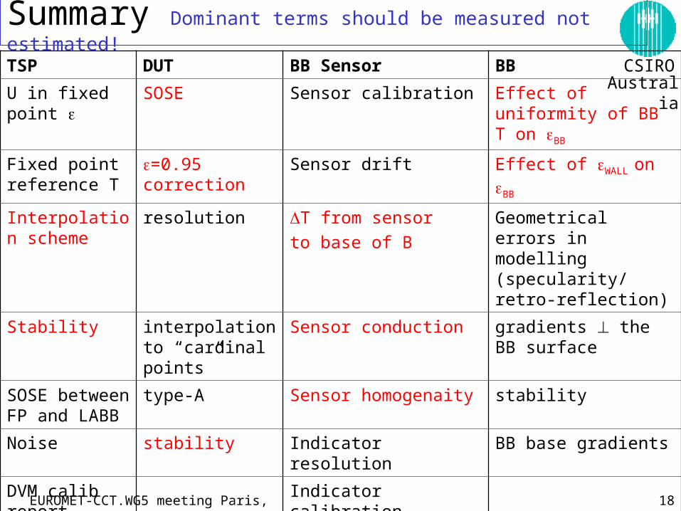
Summary Dominant terms should be measured not estimated!
TSP DUT BB Sensor BB
U in fixed point SOSE Sensor calibration Effect of uniformity of BB T on BB
Fixed point reference T
=0.95 correction Sensor drift Effect of WALL on BB
Interpolation scheme
resolution T from sensor
to base of B
Geometrical errors in modelling (specularity/ retro-reflection)
Stability interpolation to “cardinal points”
Sensor conduction gradients the BB surface
SOSE between FP and LABB
type-A Sensor homogenaity stability
Noise stability Indicator resolution BB base gradients
DVM calib report Indicator calibration
DVM reported max. error
Indicator stability
DVM 2 year drift Indicator type-A