Embed Size (px)
Citation preview

CSE140 MIDTERM 2 REVIEW Xinyuan Wang 02/13/2016
Outline • Universal Gates
• Universal sets • Other gates: properties and usage
• Sequential Networks • Types of Flip-Flops • Finite State Machine

Universal Gates • Universal Set: A set of gates that every switching
function can be implemented with the gates in this set. • Criterion: if the set of gates can implement AND, OR and
NOT gates. • Examples
• {AND, OR, NOT} universal • {AND, OR} not universal • {AND, NOT} universal • {OR, NOT} universal What can you find from the above examples?
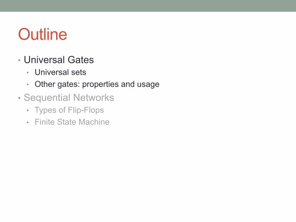
Examples • NOT is essential in the universal set • NAND, NOR is universal, but not associative • Examples
• {NAND} universal • NOT: x NAND 1 = x’ • AND: (x NAND y) NAND 1 = xy • OR : similar way
• {f(a, b, c)} where f(a, b, c) = (a+b)(b+c)(a’+b’+c’) • NOT: f(a, 1, 1) = (a+1)(1+1)(a’+0+0) = a’ • OR: f(a, 0, c) = (a+0)(0+c)(a’+1+c’) = ac • AND : similar way

XOR •
• It is a parity function, not universal • Example
• {XOR, NOT} not universal
• Properties and Usage • try to get familiar with using the below properties

Shannon’s Expansion • How to simplify such switching functions?

Shannon’s Expansion • How to simplify such switching functions?

Hints • Review Lec6, HW3 Q2 and Q3 • Try to solve examples on midterm 2 samples by yourself

Outline • Universal Gates
• Universal sets • Other gates: properties and usage
• Sequential Networks • Types of Flip-Flops • Finite State Machine

Sequential Network
• Memory: Flip flops • Specification: Finite State Machines • Implementation: Excitation Tables • Main Theme: Timing
• Present time = t and next time = t+1 • Timing constraints to separate the present and next times

Latches and Flip-Flops • SR(Set/Reset) latch
• Set: Make the output 1 (S = 1, R = 0, Q = 1) • Reset: Make the output 0 (S = 0, R = 1, Q = 0)
• if you want to know more details, refer to lec7 and HW3 Q4
• Other types

Latches and Flip-Flops • Example: D-Latch vs D Flip-Flop
• two inputs: CLK, D
• D-Latch • When CLK = 1, D passes through to Q • When CLK = 0, Q holds its previous value
• D Flip-Flop • When CLK rises from 0 to 1, D passes through
to Q • Otherwise, Q holds its previous value • Q changes only on the rising edge of CLK
(edge-triggered)

Timing Diagram • Example: D-Latch vs D Flip-Flop
• HW4, Q1

Timing Diagram • Example: D-Latch vs D Flip-Flop

Timing Diagram • What will the waveforms of other FFs look like?
• T F-F? JK F-F? • Hints: HW4 Q1 and midterm 2 samples

Finite State Machine • Describe circuit behavior over time • Canonical Form
• Mealy machine: output depends on current state and inputs
• Moore machine: output depends on current state only

Examples • HW4, Q2: output y(t) = 1 only if input x(t) has pattern
x(t-2,t) = 100 or 110. Otherwise, y(t) = 0. • Design as a Mealy machine

Examples • HW4, Q2: output y(t) = 1 only if input x(t) has pattern
x(t-2,t) = 100 or 110. Otherwise, y(t) = 0. • Design as a Mealy machine

Examples • HW4, Q2: output y(t) = 1 only if input x(t) has pattern
x(t-2,t) = 100 or 110. Otherwise, y(t) = 0. • Design as Moore machine
State Diagram State Table

Finite State Machine Method 1 • Given: Circuit implementation • Excitation(State transition) table • Identify states and derive a state table • State diagram • Input-output relation
Method 2 • Given: State diagram • Identify states and derive a state table • Excitation table • Equations(K-maps if needed) • Circuit implementation

Examples • 2012 Mid2 Q4
• D Flip-Flop: Q(t+1) = D(t) • D(t) can be find with current input X(t) and current
state Q0(t), Q1(t)

Examples • Boolean expressions of the next states and outputs
• Excitation table

Examples • Define states and derive a state diagram
• Given inputs and initial state, write down the output sequence

Examples • Define states and derive a state diagram
• Given inputs and initial state, write down the output sequence

Finite State Machine Method 1 • Given: Circuit implementation • Excitation(State transition) table • Identify states and derive a state table • State diagram • Input-output relation
Method 2 • Given: State diagram • Identify states and derive a state table • Excitation table • Equations(K-maps if needed) • Circuit implementation
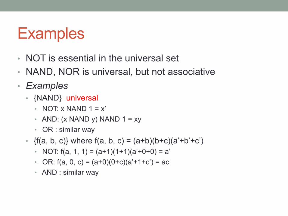
Examples • 2014FA Mid2 Q5
• With the Boolean expressions we can derive the state transition
table. It’s easy to draw to state diagram

Examples • Use JK flip-flop and a minimal AND-OR-NOT network to
implement • JK flip-flops: Q(t+1) = Q(t)K’(t) + Q’(t)J(t)
• Derive J(t) and K(t) with given Q(t), Q(t+1)

Examples • K-maps and logic diagram

Hints • Find more questions on midterm 2 samples

GOOD LUCK!