Embed Size (px)
Citation preview
CSE 370 - Fall 1999 - Introduction - 1
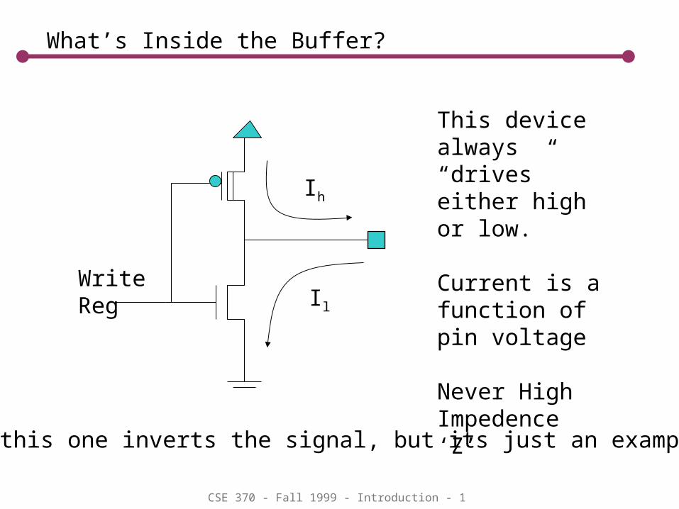
What’s Inside the Buffer?
Ih
Il
WriteReg
This device always “drives”either high or low.
Current is a function of pin voltage
Never High Impedence ‘Z’
Note: this one inverts the signal, but its just an example…

CSE 370 - Fall 1999 - Introduction - 2
I/O Port?
WriteReg
ReadReg
Pin
bus
CSE 370 - Fall 1999 - Introduction - 3
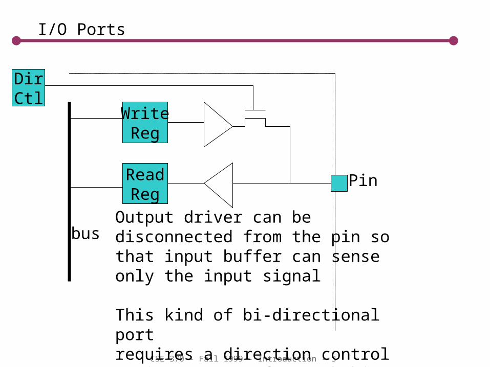
I/O Ports
WriteReg
ReadReg
Pin
bus
DirCtl
Output driver can be disconnected from the pin so that input buffer can sense only the input signal
This kind of bi-directional portrequires a direction control register (SFR) for each bit of output (like StrongArm…)
CSE 370 - Fall 1999 - Introduction - 4
The 8051 (always has to be different)
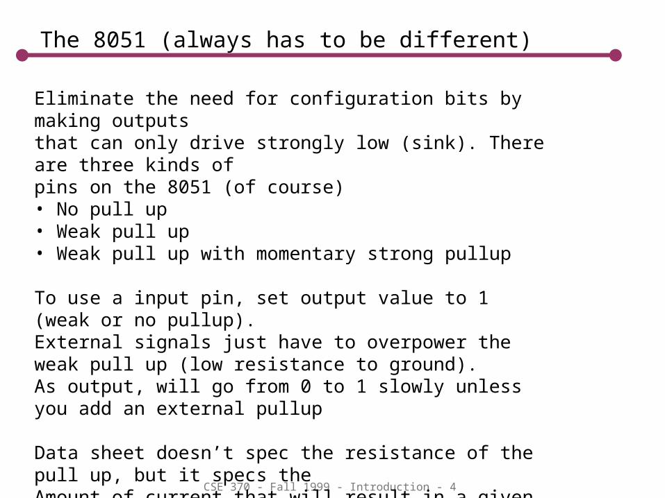
Eliminate the need for configuration bits by making outputsthat can only drive strongly low (sink). There are three kinds of pins on the 8051 (of course)• No pull up• Weak pull up• Weak pull up with momentary strong pullup
To use a input pin, set output value to 1 (weak or no pullup). External signals just have to overpower the weak pull up (low resistance to ground). As output, will go from 0 to 1 slowly unless you add an external pullup
Data sheet doesn’t spec the resistance of the pull up, but it specs theAmount of current that will result in a given voltage at the pin. ForExample, in Ports 1,2,3 Ioh = -25uA at .75Vcc.
CSE 370 - Fall 1999 - Introduction - 5
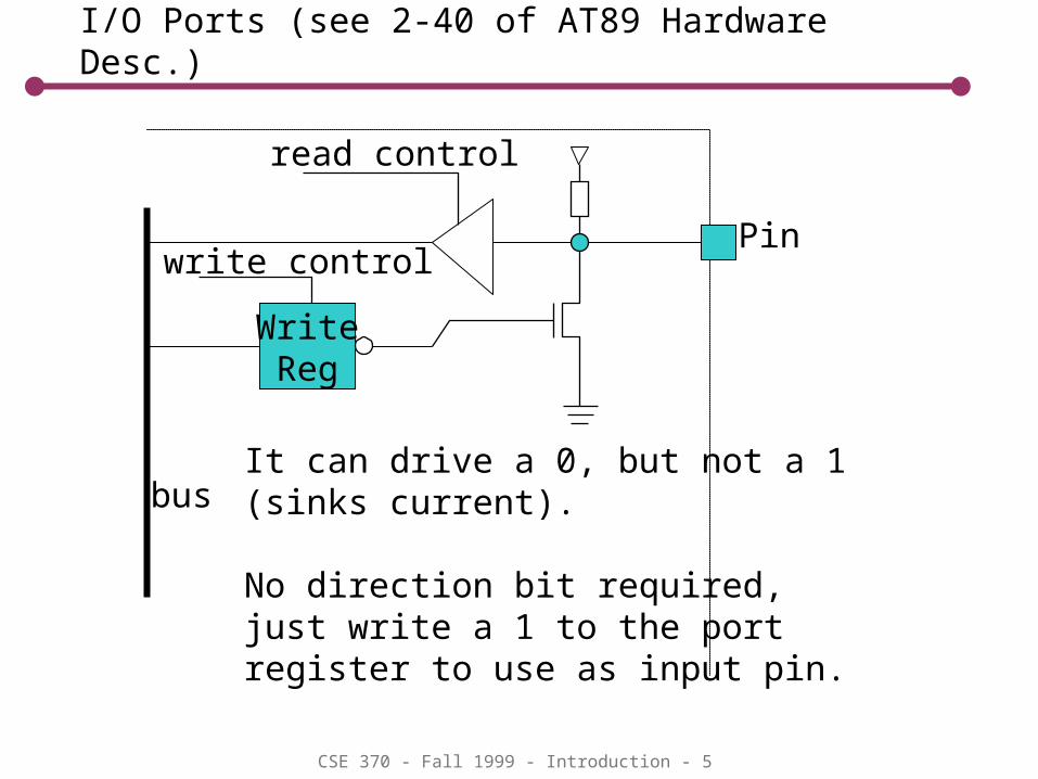
I/O Ports (see 2-40 of AT89 Hardware Desc.)
WriteReg
Pin
busIt can drive a 0, but not a 1 (sinks current).
No direction bit required, just write a 1 to the port register to use as input pin.
read control
write control
CSE 370 - Fall 1999 - Introduction - 6
Application: External I/O bus
8051
8051
8051
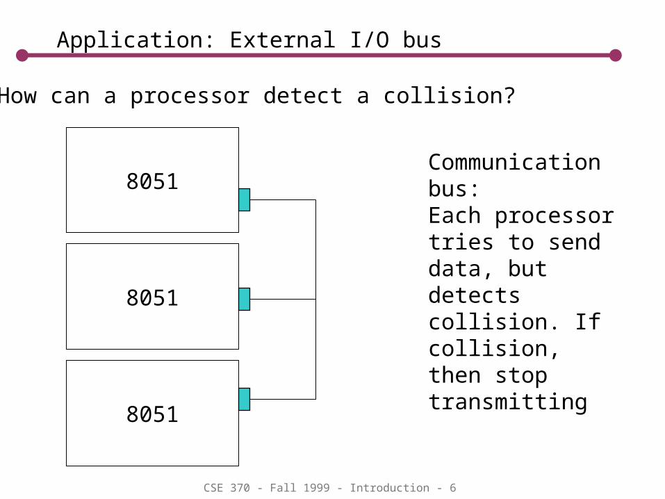
Communication bus:Each processor tries to send data, but detects collision. If collision, then stop transmitting
Q1) How can a processor detect a collision?

CSE 370 - Fall 1999 - Introduction - 7
Summary
Port 0: used as address bus for external address/data bus. Uses active
pullup in this mode. Fast Can use as GPIO. Must use external pullup. Pullup size is
power/speed tradeoff, can sink up to 3.2mA while maintaining a logic zero output.
Port 1 and 3: GPIO only. External pullups are optional. Power/speed tradeoff,
can sink up to 1.6mA while maintaining a logic zero output
Port 2: Also used for external address bus. Has active and passive internal
pullups. External pullups are optional in GPIO mode, up to 1.6mA.

CSE 370 - Fall 1999 - Introduction - 8
Example Problem (See elec. specs in AT89C55)
P1Open = 0Closed = 1
R
1) As big as possible!
According to Data sheet:Processor reads a zero if Vpin < .2Vcc - .3 = 0.7VIlow (port 1) is .45V at 50uA. So what is max R?
(.45/50e-6) = 9Kohms So the switch resistor better be smaller than 9Kohms. 4.7K
is a good choice. 2.7 is okay but higher power!
Vp

CSE 370 - Fall 1999 - Introduction - 9
Careful w/ Coils (motors, valves, etc)
Current limiterR = 50Ohms
Coil (L)
MOSFETSwitch
8051
Steady state on current: Vcc/RVds ~ 0 (Rds ~ 4mOhm)But, when we try to turn off theMosfet quickly, what happens?
•Rds goes up quickly, but Ids drops slowly)•If Rds becomes 1K, then Vds becomes 100V•And instantaneous power becomes 10W
I =0 .1A
Vds

CSE 370 - Fall 1999 - Introduction - 10
Absolute Maximum Current Ratings
Is there a limit to how much current we can sink if we don’t care about what happens to our logic levels?
How much current did you sink in Lab1?
What was the voltage at the pin?
What is the maximum legal speaker power on port 0? 10mA @ 8ohms = .8mW …. we want 200mW!

CSE 370 - Fall 1999 - Introduction - 11
Design Meeting
How are we going to make louder more interesting sounds??Sample rate v. Frequency
How can we generate a complex tone (muliple notes simulaneously)
How should we use timers/interrupts to do siren?
What is midi?
Spreadsheet for tone generation

CSE 370 - Fall 1999 - Introduction - 12
Using single bit tones
0
0.5
1
1.5
2
2.51 4 7 10 13 16 19 22 25 28 31
tone1
tone2
sum
• Two tones generated by two single bit outputs. • How do we add tone1 and tone2.
CSE 370 - Fall 1999 - Introduction - 13
Our Version
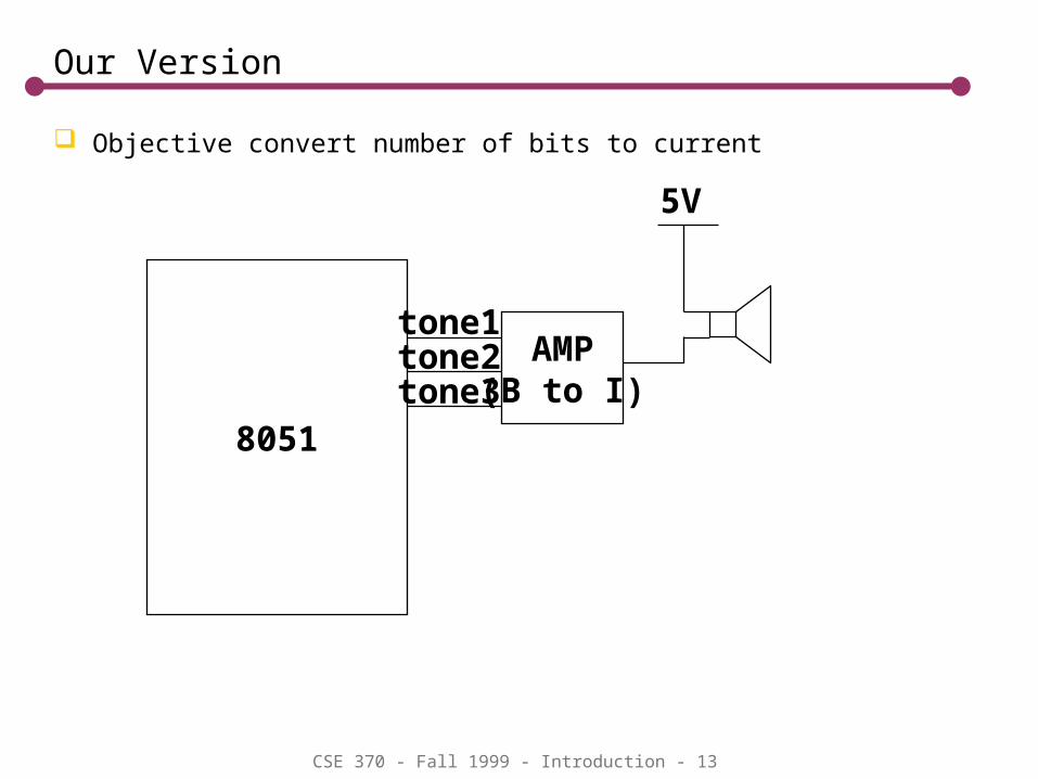
Objective convert number of bits to current
8051
AMP(B to I)
tone1tone2tone3
5V

CSE 370 - Fall 1999 - Introduction - 14
One Idea
8051
tone1tone2tone3
8ohms
Does this sum? (I = Bx) What must R be to protect the processor?What is the worst case (1, 2, or 3 bits)?How much power are we putting
through the speaker in the worst case?
5V
R=?
Close. Vs decreases with increasing B. So each Ir decreases with increasing B.
Constraints5/(8+R)<10mA5/(8+R/3)<26mA
3 bits is worse (Higher R constraint)(26mA)^2 * 8= 5.4mW
Vs

CSE 370 - Fall 1999 - Introduction - 15
Another Idea
Use a current amplifier (PNP Transistor) Ice <= Ib (assume =100) Assume Vbe = 0.7V when “on” Assume Vce = 1V when “on” Assume tone1 = 0V Pick Rc to protect the speaker Pick Rb to protect the processor
e
cb
8ohms
5V
8051
tone1 <Ib
Ib
Is = ((.2/8)^.5)/3 = ~50mARc: 5 – (50mA*8) – Vce – (50mA * Rc) = 0so: Rc = (5 – 1 – 0.4)/.05 = 72ohms Rb: Vb/1mA = [5 – (8*.05) - .7]/1mA = 3.9K!
Rc
Rb

CSE 370 - Fall 1999 - Introduction - 16
Final Circuit Design
8051
tone1tone2tone3
Rb
8ohms
5VSize R to match your speaker and toStay within the current limitations of theProcessor.
Rc

CSE 370 - Fall 1999 - Introduction - 17
Ideal Solution
Digital to Analog Converter
8051
DAC
8AMP
(V to I)
Voltage signal
Speaker cares about current, not voltageWhat is algorithm to superimpose 1KHz tone with 500Hz toneWith a sampling rate of 10KHz
SW?

CSE 370 - Fall 1999 - Introduction - 18
Software Summation
Add waveforms to get multiple tones (think current through speaker, not voltage)
0
0.5
1
1.5
2
2.5
3
3.5
4
1 4 7 10
13
16
19
22
25
28
31
tone1
tone2
tone3
Note that lower frequency is smoother for a given sample rate

CSE 370 - Fall 1999 - Introduction - 19
What should we do in the next lab?

CSE 370 - Fall 1999 - Introduction - 20
Synthesizer Algorithm
Let sin[] be a look up table with 256 entries (1 complete cycle)
Every .1ms (10KHz) P2 = sin[t1] + sin[t2] + sin[t3] … For 1KHz, t1 += 256/10 is this hard? how do we implement this? For 500Hz, t2 += 256/20 At 8-bit resolution we can vary output from 0 to 255. Hi frequencies are smoother
Can Compute arbitrary waveforms (not just tone summations)
0
255
128

CSE 370 - Fall 1999 - Introduction - 21
Summary
Review of basic Electronics Capacitors Inductors Bipolar Transistors MOS transistors
Review of 8051 I/O configuration

![ìx== v I ir- of › ~mcgladm › Geography 313 Pacific Northwest › for … · Odyssey: Unive ILL Numb er.828g7gg2 l I ll]] l]ll ililt ilfi ilil ffit illt ilil| llll llll' Mansfield](https://img.pdfslide.us/doc/110x75/5f1787c85981d24da32bc9d6/x-v-i-ir-of-a-mcgladm-a-geography-313-pacific-northwest-a-for-odyssey.jpg)


![Model€¦ · !1 d ci u.: GX [Ilil]] [Ilil]] [Ilil]] [Ilil]] [Ilil]] [Ilil]] [Ilil]] ----- 0 0 a:::](https://img.pdfslide.us/doc/110x75/6054d6aaba56cd37f74bbcba/model-1-d-ci-u-gx-ilil-ilil-ilil-ilil-ilil-ilil-ilil-.jpg)

![ililililililil||ilil]ilil tl - Addicted To Costco! · PDF files8.gg* WITH COUPON Velvet Wipe & Cleon 10 x 2 pock 912.2s-Q3.25 t8.99 ex VAT ... Joby Gorillo lorch I 3 brighlnes setlings](https://img.pdfslide.us/doc/110x75/5a78514f7f8b9aa3688e9c4a/ililililililililililil-tl-addicted-to-costco-a-s8gg-with-coupon-velvet.jpg)