Embed Size (px)
Citation preview

CSE 3213 Summer 2008
CSE3213 Computer Network ICSE3213 Computer Network I
Chapter 2Application Layer Protocols & IP
Utilities
Course page:http://www.cse.yorku.ca/course/3213
Slides modified from Alberto Leon-Garcia and Indra Widjaja

CSE 3213 Summer 2008
Protocols, Services & Protocols, Services & LayeringLayering

CSE 3213 Summer 2008
Layers, Services & ProtocolsLayers, Services & Protocols
• The overall communications process between two or more machines connected across one or more networks is very complex
• Layering partitions related communications functions into groups that are manageable
• Each layer provides a service to the layer above
• Each layer operates according to a protocol• Let’s use examples to show what we mean

CSE 3213 Summer 2008
Web Browsing ApplicationWeb Browsing Application
• World Wide Web allows users to access resources (i.e. documents) located in computers connected to the Internet
• Documents are prepared using HyperText Markup Language (HTML)
• A browser application program is used to access the web
• The browser displays HTML documents that include links to other documents
• Each link references a Uniform Resource Locator (URL) that gives the name of the machine and the location of the given document
• Let’s see what happens when a user clicks on a link

CSE 3213 Summer 2008
• User clicks on http://www.nytimes.com/• URL contains Internet name of machine (
www.nytimes.com), but not Internet address• Internet needs Internet address to send information to a
machine• Browser software uses Domain Name System (DNS)
protocol to send query for Internet address• DNS system responds with Internet address
Q. www.nytimes.com?
A. 64.15.247.2001. DNS1. DNS

CSE 3213 Summer 2008
• Browser software uses HyperText Transfer Protocol (HTTP) to send request for document
• HTTP server waits for requests by listening to a well-known port number (80 for HTTP)
• HTTP client sends request messages through an “ephemeral port number,” e.g. 1127
• HTTP needs a Transmission Control Protocol (TCP) connection between the HTTP client and the HTTP server to transfer messages reliably
TCP Connection RequestFrom: 128.100.11.13 Port 1127To: 64.15.247.200 Port 80
2. TCP2. TCPACK, TCP Connection RequestFrom: 64.15.247.200 Port 80 To:128.100.11.13 Port 1127
ACK

CSE 3213 Summer 2008
• HTTP client sends its request message: “GET …”• HTTP server sends a status response: “200 OK”• HTTP server sends requested file• Browser displays document
• Clicking a link sets off a chain of events across the Internet!• Let’s see how protocols & layers come into play…
GET / HTTP/1.1
200 OK
3. HTTP3. HTTPContent

CSE 3213 Summer 2008
ProtocolsProtocols
• A protocol is a set of rules that governs how two or more communicating entities in a layer are to interact
• Messages that can be sent and received• Actions that are to be taken when a
certain event occurs, e.g. sending or receiving messages, expiry of timers
• The purpose of a protocol is to provide a service to the layer above

CSE 3213 Summer 2008
LayersLayers
• A set of related communication functions that can be managed and grouped together
• Application Layer: communications functions that are used by application programs– HTTP, DNS, SMTP (email)
• Transport Layer: end-to-end communications between two processes in two machines– TCP, User Datagram Protocol (UDP)
• Network Layer: node-to-node communications between two machines– Internet Protocol (IP)

CSE 3213 Summer 2008
Example: HTTPExample: HTTP
• HTTP is an application layer protocol• Retrieves documents on behalf of a
browser application program• HTTP specifies fields in request messages
and response messages– Request types; Response codes– Content type, options, cookies, …
• HTTP specifies actions to be taken upon receipt of certain messages

CSE 3213 Summer 2008
HTTPClient
HTTP ProtocolHTTP Protocol
GET
Response
HTTPServer
• HTTP assumes messages can be exchanged directly between HTTP client and HTTP server
• In fact, HTTP client and server are processes running in two different machines across the Internet
• HTTP uses the reliable stream transfer service provided by TCP

CSE 3213 Summer 2008
Example: TCPExample: TCP
• TCP is a transport layer protocol• Provides reliable byte stream service between two
processes in two computers across the Internet• Sequence numbers keep track of the bytes that
have been transmitted and received• Error detection and retransmission used to recover
from transmission errors and losses• TCP is connection-oriented: the sender and
receiver must first establish an association and set initial sequence numbers before data is transferred
• Connection ID is specified uniquely by (send port #, send IP address, receive port #, receiver IP
address)

CSE 3213 Summer 2008
HTTPserver
HTTPclient
TCP
Port 80Port 1127
HTTP uses service of TCPHTTP uses service of TCP
TCP
ResponseGET
TCP80, 1127 GET 1127, 80 bytesResponseGETResponse

CSE 3213 Summer 2008
Example: DNS ProtocolExample: DNS Protocol
• DNS protocol is an application layer protocol• DNS is a distributed database that resides in
multiple machines in the Internet• DNS protocol allows queries of different
types– Name-to-address or Address-to-name– Mail exchange
• DNS usually involves short messages and so uses service provided by UDP
• Well-known port 53

CSE 3213 Summer 2008
• Local Name Server: resolve frequently-used names– University department, ISP– Contacts Root Name server if it cannot resolve query
• Root Name Servers: 13 globally– Resolves query or refers query to Authoritative Name Server
• Authoritative Name Server: last resort– Every machine must register its address with at least two
authoritative name servers
12 3
45
6
LocalNameServer
RootNameServer
AuthoritativeNameServer

CSE 3213 Summer 2008
Example: UDPExample: UDP
• UDP is a transport layer protocol• Provides best-effort datagram service
between two processes in two computers across the Internet
• Port numbers distinguish various processes in the same machine
• UDP is connectionless• Datagram is sent immediately• Quick, simple, but not reliable

CSE 3213 Summer 2008
SummarySummary• Layers: related communications functions
– Application Layer: HTTP, DNS– Transport Layer: TCP, UDP– Network Layer: IP
• Services: a protocol provides a communications service to the layer above– TCP provides connection-oriented reliable byte
transfer service– UDP provides best-effort datagram service
• Each layer builds on services of lower layers– HTTP builds on top of TCP– DNS builds on top of UDP– TCP and UDP build on top of IP

CSE 3213 Summer 2008
OSI Reference ModelOSI Reference Model

CSE 3213 Summer 2008
Why Layering?Why Layering?
• Layering simplifies design, implementation, and testing by partitioning overall communications process into parts
• Protocol in each layer can be designed separately from those in other layers
• Protocol makes “calls” for services from layer below
• Layering provides flexibility for modifying and evolving protocols and services without having to change layers below
• Monolithic non-layered architectures are costly, inflexible, and soon obsolete

CSE 3213 Summer 2008
Open Systems InterconnectionOpen Systems Interconnection
• Network architecture:– Definition of all the layers – Design of protocols for every layer
• By the 1970s every computer vendor had developed its own proprietary layered network architecture
• Problem: computers from different vendors could not be networked together
• Open Systems Interconnection (OSI) was an international effort by the International Organization for Standardization (ISO) to enable multivendor computer interconnection

CSE 3213 Summer 2008
OSI Reference ModelOSI Reference Model
• Describes a seven-layer abstract reference model for a network architecture
• Purpose of the reference model was to provide a framework for the development of protocols
• OSI also provided a unified view of layers, protocols, and services which is still in use in the development of new protocols
• Detailed standards were developed for each layer, but most of these are not in use
• TCP/IP protocols preempted deployment of OSI protocols

CSE 3213 Summer 2008
7-Layer OSI Reference Model7-Layer OSI Reference Model
ApplicationLayer
PresentationLayer
SessionLayer
TransportLayer
NetworkLayer
Data LinkLayer
PhysicalLayer
ApplicationLayer
PresentationLayer
SessionLayer
TransportLayer
NetworkLayer
Data LinkLayer
PhysicalLayer
NetworkLayer
Application Application
Data LinkLayer
PhysicalLayer
NetworkLayer
Data LinkLayer
PhysicalLayer
Communicating End SystemsOne or More Network Nodes
End-to-End Protocols

CSE 3213 Summer 2008
Physical LayerPhysical Layer
• Transfers bits across link• Definition & specification of the physical
aspects of a communications link– Mechanical: cable, plugs, pins...– Electrical/optical: modulation, signal strength,
voltage levels, bit times, …– functional/procedural: how to activate,
maintain, and deactivate physical links…
• Ethernet, DSL, cable modem, telephone modems…
• Twisted-pair cable, coaxial cable optical fiber, radio, infrared, …

CSE 3213 Summer 2008
Data Link LayerData Link Layer
• Transfers frames across direct connections• Groups bits into frames• Detection of bit errors; Retransmission of frames• Activation, maintenance, & deactivation of data
link connections• Medium access control for local area networks• Flow control
Data LinkLayer
PhysicalLayer
Data LinkLayer
PhysicalLayer
frames
bits

CSE 3213 Summer 2008
Network LayerNetwork Layer
• Transfers packets across multiple links and/or multiple networks
• Addressing must scale to large networks• Nodes jointly execute routing algorithm to
determine paths across the network• Forwarding transfers packet across a node• Congestion control to deal with traffic
surges• Connection setup, maintenance, and
teardown when connection-based

CSE 3213 Summer 2008
InternetworkingInternetworking
• Internetworking is part of network layer and provides transfer of packets across multiple possibly dissimilar networks
• Gateways (routers) direct packets across networks
G = gateway H = host
Net 1
Net 5
Net 3
Net 2
HNet 3
G
H
H
H
GG
GG
G
Net 1
Net 2 Net 4
Net 5
Ethernet LAN
ATMSwitch
ATMSwitch
ATMSwitch
ATMSwitch
ATMNetwork

CSE 3213 Summer 2008
Transport LayerTransport Layer
• Transfers data end-to-end from process in a machine to process in another machine
• Reliable stream transfer or quick-and-simple single-block transfer
• Port numbers enable multiplexing• Message segmentation and reassembly• Connection setup, maintenance, and release
TransportLayer
NetworkLayer
TransportLayer
NetworkLayer
NetworkLayer
NetworkLayer
Communication Network

CSE 3213 Summer 2008
Application & Upper LayersApplication & Upper Layers
• Application Layer: Provides services that are frequently required by applications: DNS, web acess, file transfer, email…
• Presentation Layer: machine-independent representation of data…
• Session Layer: dialog management, recovery from errors, …
ApplicationLayer
PresentationLayer
SessionLayer
TransportLayer
Application
ApplicationLayer
TransportLayer
Application
Incorporated into Application Layer

CSE 3213 Summer 2008
Headers & TrailersHeaders & Trailers• Each protocol uses a header that carries addresses,
sequence numbers, flag bits, length indicators, etc…• CRC check bits may be appended for error detection
ApplicationLayer
TransportLayer
NetworkLayer
Data LinkLayer
PhysicalLayer
ApplicationLayer
TransportLayer
NetworkLayer
Data LinkLayer
PhysicalLayer
Application ApplicationAPP DATA
AH APP DATA
TH AH APP DATA
NH TH AH APP DATA
DH NH TH AH APP DATA CRC
bits
CSE 3213 Summer 2008
OSI Unified View: ProtocolsOSI Unified View: Protocols
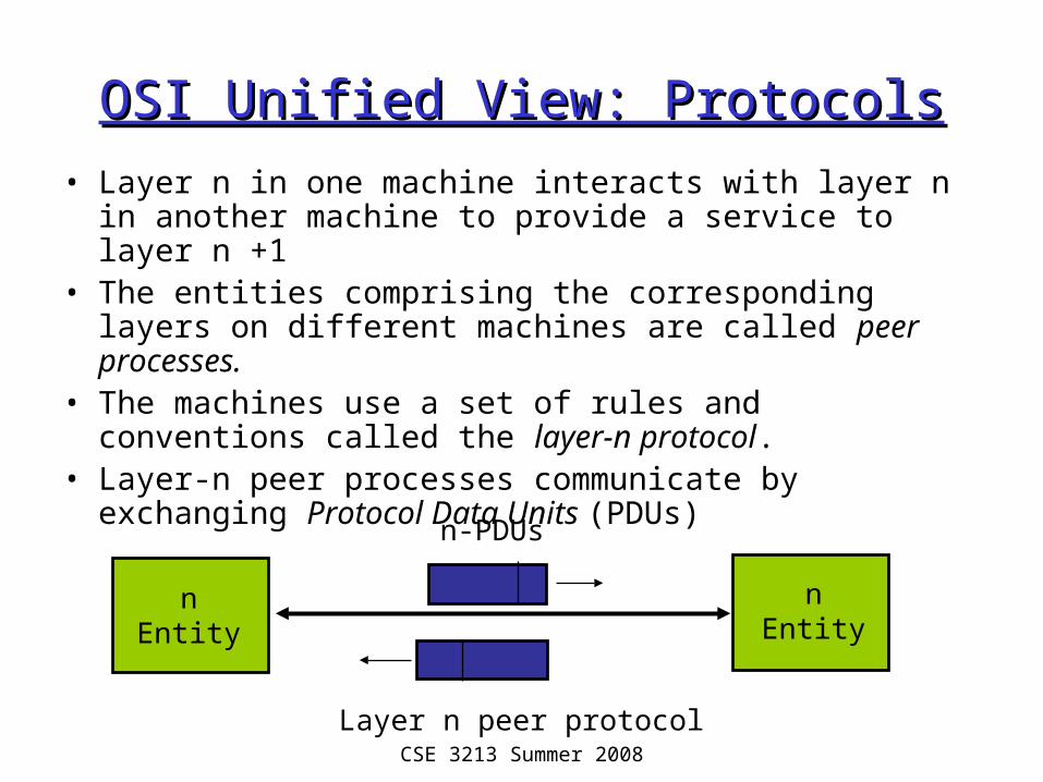
• Layer n in one machine interacts with layer n in another machine to provide a service to layer n +1
• The entities comprising the corresponding layers on different machines are called peer processes.
• The machines use a set of rules and conventions called the layer-n protocol.
• Layer-n peer processes communicate by exchanging Protocol Data Units (PDUs)
nEntity
nEntity
Layer n peer protocol
n-PDUs

CSE 3213 Summer 2008
OSI Unified View: ServicesOSI Unified View: Services
• Communication between peer processes is virtual and actually indirect
• Layer n+1 transfers information by invoking the services provided by layer n
• Services are available at Service Access Points (SAP’s)
• Each layer passes data & control information to the layer below it until the physical layer is reached and transfer occurs
• The data passed to the layer below is called a Service Data Unit (SDU)
• SDU’s are encapsulated in PDU’s

CSE 3213 Summer 2008
n+1entity
n-SAP
n+1entity
n-SAP
n entity n entity
n-SDU
n-SDU
n-SDU
H
H n-SDU
n-PDU
Layers, Services & ProtocolsLayers, Services & Protocols

CSE 3213 Summer 2008
Interlayer InteractionInterlayer Interaction
layer
N+1 user N provider
System A System B
N provider N+1 user
RequestIndication
Response
Confirm

CSE 3213 Summer 2008
Connectionless & Connection-Oriented Connectionless & Connection-Oriented ServicesServices
• Connection-Oriented– Three-phases:
1. Connection setup between two SAPs to initialize state information
2. SDU transfer3. Connection release
– E.g. TCP, ATM
• Connectionless– Immediate SDU
transfer– No connection setup– E.g. UDP, IP
• Layered services need not be of same type– TCP operates over IP – IP operates over ATM

CSE 3213 Summer 2008
n-PDU
Segmentation & ReassemblySegmentation & Reassembly
• A layer may impose a limit on the size of a data block that it can transfer for implementation or other reasons
• Thus a layer-n SDU may be too large to be handled as a single unit by layer-(n-1)
• Sender side: SDU is segmented into multiple PDUs
• Receiver side: SDU is reassembled from sequence of PDUs
n-SDU
n-PDU n-PDU n-PDU
Segmentation(a)
n-SDU
n-PDU n-PDU
Reassembly(b)

CSE 3213 Summer 2008
MultiplexingMultiplexing• Sharing of layer n service by multiple layer n+1 users• Multiplexing tag or ID required in each PDU to
determine which users an SDU belongs to
n+1entity
n+1entity
n+1entity
n+1entity
n entity n entity
n-SDUn-SDU
n-SDUH
H n-SDU
n-PDU

CSE 3213 Summer 2008
SummarySummary• Layers: related communications functions
– Application Layer: HTTP, DNS– Transport Layer: TCP, UDP– Network Layer: IP
• Services: a protocol provides a communications service to the layer above– TCP provides connection-oriented reliable byte
transfer service– UDP provides best-effort datagram service
• Each layer builds on services of lower layers– HTTP builds on top of TCP– DNS builds on top of UDP– TCP and UDP build on top of IP

CSE 3213 Summer 2008
TCP/IP ArchitectureHow the Layers Work
Together

CSE 3213 Summer 2008
Why Internetworking?Why Internetworking?• To build a “network of networks” or internet
– operating over multiple, coexisting, different network technologies
– providing ubiquitous connectivity through IP packet transfer – achieving huge economies of scale
G
GG
GG
G
H
Net 5Net 5
HNet 5Net 2
H
Net 5Net 3H
Net 5Net 1
Net 5Net 4

CSE 3213 Summer 2008
Why Internetworking?Why Internetworking?• To provide universal communication services
– independent of underlying network technologies– providing common interface to user applications
G
GG
GG
G
H
Net 5Net 5
HNet 5Net 2
H
Net 5Net 3H
Net 5Net 1
Net 5Net 4
Reliable Stream Service
User Datagram Service

CSE 3213 Summer 2008
Why Internetworking?Why Internetworking?• To provide distributed applications
– Any application designed to operate based on Internet communication services immediately operates across the entire Internet
– Rapid deployment of new applications• Email, WWW, Peer-to-peer
– Applications independent of network technology• New networks can be introduced below• Old network technologies can be retired

CSE 3213 Summer 2008
Internet Protocol ApproachInternet Protocol Approach IP packets transfer information across Internet
Host A IP → router→ router…→ router→ Host B IP IP layer in each router determines next hop (router) Network interfaces transfer IP packets across networks
Router
InternetLayer
NetworkInterface
TransportLayer
InternetLayer
NetworkInterface
TransportLayer
InternetLayer
NetworkInterface
Host A Host B
Net 5Net 1
Net 5Net 2 Net 5Net 3
Router
InternetLayer
NetworkInterface
Router
InternetLayer
NetworkInterface
Net 5Net 4

CSE 3213 Summer 2008
TCP/IP Protocol Suite
(ICMP, ARP)
Diverse network technologies
Reliable stream service
Userdatagram service
Distributed applications
HTTP SMTP RTP
TCP UDP
IP
Network
interface 1
Network
interface 3
Network
interface 2
DNS
Best-effort connectionless packet transfer

CSE 3213 Summer 2008
Internet Names & AddressesInternet Names & AddressesInternet Names• Each host a a unique name
– Independent of physical location
– Facilitate memorization by humans
– Domain Name– Organization under single
administrative unit• Host Name
– Name given to host computer
• User Name– Name assigned to user
Internet Addresses• Each host has globally unique
logical 32 bit IP address• Separate address for each
physical connection to a network • Routing decision is done based
on destination IP address • IP address has two parts:
– netid and hostid– netid unique – netid facilitates routing
• Dotted Decimal Notation:int1.int2.int3.int4(intj = jth octet)128.100.10.13
DNS resolves IP name to IP address

CSE 3213 Summer 2008
Physical AddressesPhysical Addresses
• LANs (and other networks) assign physical addresses to the physical attachment to the network
• The network uses its own address to transfer packets or frames to the appropriate destination
• IP address needs to be resolved to physical address at each IP network interface
• Example: Ethernet uses 48-bit addresses– Each Ethernet network interface card (NIC) has globally
unique Medium Access Control (MAC) or physical address
– First 24 bits identify NIC manufacturer; second 24 bits are serial number
– 00:90:27:96:68:07 12 hex numbersIntel

CSE 3213 Summer 2008
Example internetExample internet
(1,1) s
(1,2)
w
(2,1)
(1,3) r (2,2)PPP
Netid=2
Ethernet(netid=1)
PCServerRouter
Workstation
netid hostidPhysical address
server 1 1 s
workstation 1 2 w
router 1 3 r
router 2 1 -
PC 2 2 -
*PPP does not use addresses

CSE 3213 Summer 2008
EncapsulationEncapsulation
Ethernet header contains: source and destination physical addresses network protocol type (e.g. IP)
IP header IP Payload
Ethernet header
FCSIP
header IP Payload

CSE 3213 Summer 2008
IP packet from workstation to serverIP packet from workstation to server
1. IP packet has (1,2) IP address for source and (1,1) IP address for destination
2. IP table at workstation indicates (1,1) connected to same network, so IP packet is encapsulated in Ethernet frame with addresses w and s
3. Ethernet frame is broadcast by workstation NIC and captured by server NIC
4. NIC examines protocol type field and then delivers packet to its IP layer
(1,1) s
(1,2)
w
(2,1)
(1,3) r (2,2)PPP
Ethernet
PCServerRouter
Workstation
(1,2), (1,1) w, s

CSE 3213 Summer 2008
IP packet from server to PCIP packet from server to PC
(1,1) s
(1,2)
w
(2,1)
(1,3) r (2,2)
PCServerRouter
Workstation
1. IP packet has (1,1) and (2,2) as IP source and destination addresses 2. IP table at server indicates packet should be sent to router, so IP packet is
encapsulated in Ethernet frame with addresses s and r3. Ethernet frame is broadcast by server NIC and captured by router NIC4. NIC examines protocol type field and then delivers packet to its IP layer5. IP layer examines IP packet destination address and determines IP packet should
be routed to (2,2)6. Router’s table indicates (2,2) is directly connected via PPP link7. IP packet is encapsulated in PPP frame and delivered to PC8. PPP at PC examines protocol type field and delivers packet to PC IP layer
(1,1), (2,2) s, r
(1,1), (2,2)

CSE 3213 Summer 2008
How the layers work togetherHow the layers work together
Network interface
IP
TCP
HTTP
Network interface
IP
Network interface
IP
TCP
HTTP
Ethernet PPPRouter
(1,1) s
(2,1)
(1,3) r (2,2)PPP
Ethernet
(a)
(b) Server PC
PCServerRouter
TCP uses node-to-node Unreliable packet transfer of IP
Server IP address & PC IP address
Internet
HTTP uses process-to-processReliable byte stream transfer of
TCP connection: Server socket: (IP Address, 80)PC socket (IP Address, Eph. #)

CSE 3213 Summer 2008
EncapsulationEncapsulation
TCP Header contains source & destination
port numbers
IP Header contains source and destination
IP addresses; transport protocol type
Ethernet Header contains source & destination MAC addresses; network protocol type
HTTP Request
TCP header HTTP Request
IP header
TCP header HTTP Request
Ethernet header
IP header
TCP header HTTP Request FCS

CSE 3213 Summer 2008
• User clicks on http://www.nytimes.com/• Ethereal network analyzer captures all frames
observed by its Ethernet NIC• Sequence of frames and contents of frame can be
examined in detail down to individual bytes
How the layers work together: How the layers work together: Network Analyzer ExampleNetwork Analyzer Example
Internet

CSE 3213 Summer 2008
Ethereal windowsEthereal windowsTop Pane
shows frame/packet
sequence
Middle Pane shows
encapsulation for a given frame
Bottom Pane shows hex & text

CSE 3213 Summer 2008
Top pane: frame sequenceTop pane: frame sequenceDNS
Query
TCP Connection
SetupHTTP
Request & Response

CSE 3213 Summer 2008
Middle pane: EncapsulationMiddle pane: Encapsulation
Ethernet Frame
Ethernet Destination and
Source Addresses
Protocol Type

CSE 3213 Summer 2008
Middle pane: EncapsulationMiddle pane: Encapsulation
IP Packet
IP Source and Destination Addresses
Protocol Type
And a lot of other stuff!

CSE 3213 Summer 2008
Middle pane: EncapsulationMiddle pane: Encapsulation
TCP Segment
Source and Destination Port
Numbers
HTTP Request
GET

CSE 3213 Summer 2008
SummarySummary
• Encapsulation is key to layering• IP provides for transfer of packets across
diverse networks• TCP and UDP provide universal
communications services across the Internet• Distributed applications that use TCP and
UDP can operate over the entire Internet• Internet names, IP addresses, port numbers,
sockets, connections, physical addresses

CSE 3213 Summer 2008
Application Layer Protocols & IP Application Layer Protocols & IP UtilitiesUtilities

CSE 3213 Summer 2008
Telnet (RFC 854)Telnet (RFC 854)
• Provides general bi-directional byte-oriented TCP-based communications facility (Network Virtual Terminal)
• Initiating machine treated as local to the remote host
• Used to connect to port # of other servers and to interact with them using command line
NVTNVT
Server process

CSE 3213 Summer 2008
Network Virtual TerminalNetwork Virtual Terminal
• Network Virtual Terminal• Lowest common denominator terminal• Each machine maps characteristics to NVT• Negotiate options for changes to the NVT• Data input sent to server & echoed back• Server control functions : interrupt, abort
output, are-you-there, erase character, erase line
• Default requires login & password

CSE 3213 Summer 2008
telnettelnet
• A program that uses the Telnet protocol• Establishes TCP socket• Sends typed characters to server• Prints whatever characters arrive• Try it to retrieve a web page (HTTP) or to
send an email (SMTP)

CSE 3213 Summer 2008
File Transfer Protocol (RFC 959)File Transfer Protocol (RFC 959)
• Provides for transfer of file from one machine to another machine
• Designed to hide variations in file storage• FTP parameter commands specify file info
– File Type: ASCII, EBCDIC, image, local.– Data Structure: file, record, or page– Transmission Mode: stream, block,
compressed
• Other FTP commands– Access Control: USER, PASS, CWD, QUIT, …– Service: RETR, STOR, PWD, LIST, …

CSE 3213 Summer 2008
User interface
User PI
User DTP
PI = Protocol interface DTP = Data transfer process
User FTP
Server PI
Server DTP
Server FTP
Control
connection
Data
connection
FTP File TransferFTP File Transfer

CSE 3213 Summer 2008
Two TCP ConnectionsTwo TCP Connections
Control connection– Set up using Telnet
protocol on well-known port 21
– FTP commands & replies between protocol interpreters
– PIs control the data transfer process
– User requests close of control connection; server performs the close
Data connection– To perform file transfer,
obtain lists of files, directories
– Each transfer requires new data connection
– Passive open by user PI with ephemeral port #
– Port # sent over control connection
– Active open by server using port 20
CSE 3213 Summer 2008
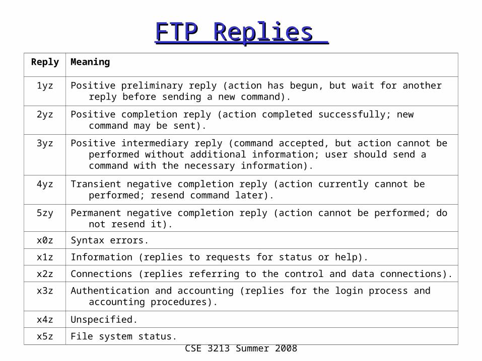
FTP Replies FTP Replies Reply Meaning
1yz Positive preliminary reply (action has begun, but wait for another reply before sending a new command).
2yz Positive completion reply (action completed successfully; new command may be sent).
3yz Positive intermediary reply (command accepted, but action cannot be performed without additional information; user should send a command with the necessary information).
4yz Transient negative completion reply (action currently cannot be performed; resend command later).
5zy Permanent negative completion reply (action cannot be performed; do not resend it).
x0z Syntax errors.
x1z Information (replies to requests for status or help).
x2z Connections (replies referring to the control and data connections).
x3z Authentication and accounting (replies for the login process and accounting procedures).
x4z Unspecified.
x5z File system status.

CSE 3213 Summer 2008
FTP Client (192.168.1.132: 1421) establishes Control FTP Client (192.168.1.132: 1421) establishes Control Connection to FTP Server (128.100.132.23: 21)Connection to FTP Server (128.100.132.23: 21)
CSE 3213 Summer 2008
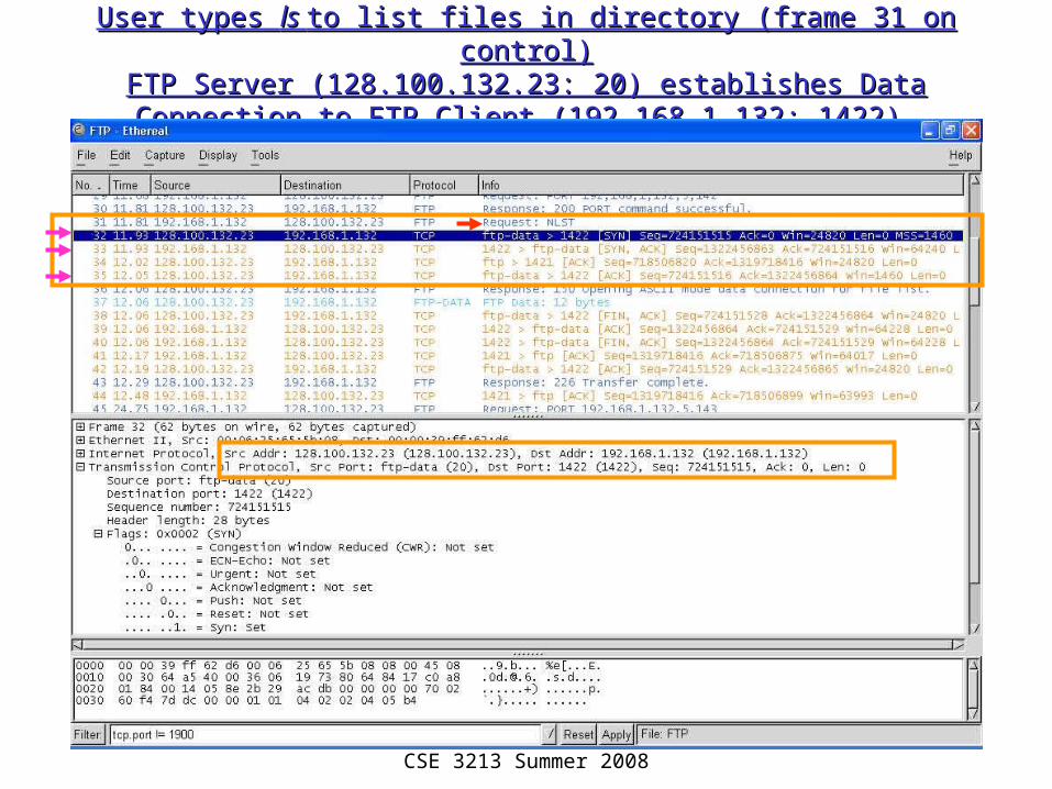
User types User types ls ls to list files in directory (frame 31 on control)to list files in directory (frame 31 on control)FTP Server (128.100.132.23: 20) establishes Data Connection to FTP Server (128.100.132.23: 20) establishes Data Connection to
FTP Client (192.168.1.132: 1422) FTP Client (192.168.1.132: 1422)

CSE 3213 Summer 2008
User types User types get index.html get index.html to request file transfer in control to request file transfer in control connection (frame 47 request); File transfer on new data connection (frame 47 request); File transfer on new data
connection (port 1423, fr. 48, 49, 51) connection (port 1423, fr. 48, 49, 51)

CSE 3213 Summer 2008
Hypertext Transfer ProtocolHypertext Transfer Protocol
• RFC 1945 (HTTP 1.0), RFC 2616 (HTTP 1.1)• HTTP provides communications between
web browsers & web servers• Web: framework for accessing documents
& resources through the Internet• Hypertext documents: text, graphics,
images, hyperlinks• Documents prepared using Hypertext
Markup Language (HTML)

CSE 3213 Summer 2008
HTTP ProtocolHTTP Protocol
• HTTP servers use well-known port 80• Client request / Server reply• Stateless: server does not keep any
information about client• HTTP 1.0 new TCP connection per
request/reply (non-persistent)• HTTP 1.1 persistent operation is default

CSE 3213 Summer 2008
HTTP Typical ExchangeHTTP Typical Exchange

CSE 3213 Summer 2008
HTTP Message FormatsHTTP Message Formats
• HTTP messages written in ASCII text• Request Message Format
– Request Line (Each line ends with carriage return)
• Method URL HTTP-Version \r\n• Method specifies action to apply to object• URL specifies object
– Header Lines (Ea. line ends with carriage return)
• Attribute Name: Attribute Value• E.g. type of client, content, identity of requester, …• Last header line has extra carriage return)
– Entity Body (Content)• Additional information to server

CSE 3213 Summer 2008
HTTP Request MethodsHTTP Request Methods
Request method
Meaning
GET Retrieve information (object) identified by the URL.
HEAD Retrieve meta-information about the object, but do not transfer the object; Can be used to find out if a document has changed.
POST Send information to a URL (using the entity body) and retrieve result; used when a user fills out a form in a browser.
PUT Store information in location named by URL
DELETE Remove object identified by URL
TRACE Trace HTTP forwarding through proxies, tunnels, etc.
OPTIONS Used to determine the capabilities of the server, or characteristics of a named resource.

CSE 3213 Summer 2008
Universal Resource LocatorUniversal Resource Locator
• Absolute URL– scheme://hostname[:port]/path– http://www.nytimes.com/
• Relative URL– /path– /

CSE 3213 Summer 2008
HTTP Request MessageHTTP Request Message
CSE 3213 Summer 2008
HTTP Response MessageHTTP Response Message
• Response Message Format– Status Line
• HTTP-Version Status-Code Message• Status Code: 3-digit code indicating result• E.g. HTTP/1.0 200 OK
– Headers Section• Information about object transferred to client• E.g. server type, content length, content type, …
– Content• Object (document)

CSE 3213 Summer 2008
HTTP Response MessageHTTP Response Message

CSE 3213 Summer 2008
HTTP Proxy Server & CachingHTTP Proxy Server & Caching
• Web users generate large traffic volumes• Traffic causes congestion & delay• Can improve delay performance and
reduce traffic in Internet by moving content to servers closer to the user
• Web proxy servers cache web information– Deployed by ISPs– Customer browsers configured to first access
ISPs proxy servers– Proxy replies immediately when it has
requested object or retrieves the object if it does not

CSE 3213 Summer 2008
Cookies and Web SessionsCookies and Web Sessions
• Cookies are data exchanged by clients & servers as header lines
• Since HTTP stateless, cookies can provide context for HTTP interaction
• Set cookie header line in reply message from server + unique ID number for client
• If client accepts cookie, cookie added to client’s cookie file (must include expiration date)
• Henceforth client requests include ID • Server site can track client interactions, store
these in a separate database, and access database to prepare appropriate responses

CSE 3213 Summer 2008
Cookie Header Line; Cookie Header Line; ID is 24 hexadecimal numeralID is 24 hexadecimal numeral

CSE 3213 Summer 2008
PINGPING
• Application to determine if host is reachable• Based on Internet Control Message Protocol
– ICMP informs source host about errors encountered in IP packet processing by routers or by destination host
– ICMP Echo message requests reply from destination host
• PING sends echo message & sequence #• Determines reachability & round-trip delay• Sometimes disabled for security reasons

CSE 3213 Summer 2008
PING from NAL hostPING from NAL host
Microsoft(R) Windows DOS(c)Copyright Microsoft Corp 1990-2001.
C:\DOCUME~1\1>ping nal.toronto.edu
Pinging nal.toronto.edu [128.100.244.3] with 32 bytes of data:
Reply from 128.100.244.3: bytes=32 time=84ms TTL=240Reply from 128.100.244.3: bytes=32 time=110ms TTL=240Reply from 128.100.244.3: bytes=32 time=81ms TTL=240Reply from 128.100.244.3: bytes=32 time=79ms TTL=240
Ping statistics for 128.100.244.3: Packets: Sent = 4, Received = 4, Lost = 0 (0% loss),Approximate round trip times in milli-seconds: Minimum = 79ms, Maximum = 110ms, Average = 88ms
C:\DOCUME~1\1>

CSE 3213 Summer 2008
TracerouteTraceroute
• Find route from local host to a remote host• Time-to-Live (TTL)
– IP packets have TTL field that specifies maximum # hops traversed before packet discarded
– Each router decrements TTL by 1– When TTL reaches 0 packet is discarded
• Traceroute– Send UDP to remote host with TTL=1– First router will reply ICMP Time Exceeded Msg– Send UDP to remote host with TTL=2, …– Each step reveals next router in path to remote host

CSE 3213 Summer 2008
Traceroute from home PC to university Traceroute from home PC to university hosthost
Tracing route to www.comm.utoronto.ca [128.100.11.60]over a maximum of 30 hops:
1 1 ms <10 ms <10 ms 192.168.2.1 2 3 ms 3 ms 3 ms 10.202.128.1 3 4 ms 3 ms 3 ms gw04.ym.phub.net.cable.rogers.com [66.185.83.142] 4 * * * Request timed out.5 47 ms 59 ms 66 ms gw01.bloor.phub.net.cable.rogers.com [66.185.80.230] 6 3 ms 3 ms 38 ms gw02.bloor.phub.net.cable.rogers.com [66.185.80.242] 7 8 ms 3 ms 5 ms gw01.wlfdle.phub.net.cable.rogers.com [66.185.80.2] 8 8 ms 7 ms 7 ms gw02.wlfdle.phub.net.cable.rogers.com [66.185.80.142] 9 4 ms 10 ms 4 ms gw01.front.phub.net.cable.rogers.com [66.185.81.18]
10 6 ms 4 ms 5 ms ra1sh-ge3-4.mt.bigpipeinc.com [66.244.223.237] 11 16 ms 17 ms 13 ms rx0sh-hydro-one-telecom.mt.bigpipeinc.com [66.244.223.246] 12 7 ms 14 ms 8 ms 142.46.4.2 13 10 ms 7 ms 6 ms utorgw.onet.on.ca [206.248.221.6] 14 7 ms 6 ms 11 ms mcl-gateway.gw.utoronto.ca [128.100.96.101] 15 7 ms 5 ms 8 ms sf-gpb.gw.utoronto.ca [128.100.96.17] 16 7 ms 7 ms 10 ms bi15000.ece.utoronto.ca [128.100.96.236] 17 7 ms 9 ms 9 ms www.comm.utoronto.ca [128.100.11.60]
Trace complete.
Home Network
Rogers CableISP
Ontario Net
University ofToronto
Hydro OneShaw Net

CSE 3213 Summer 2008
ipconfigipconfig
• Utility in Microsoft® Windows to display TCP/IP information about a host
• Many options– Simplest: IP address, subnet mask, default
gateway for the host– Information about each IP interface of a host
• DNS hostname, IP addresses of DNS servers, physical address of network card, IP address, …
– Renew IP address from DHCP server

CSE 3213 Summer 2008
netstatnetstat
• Queries a host about TCP/IP network status
• Status of network drivers & their interface cards– #packets in, #packets out, errored packets, …
• State of routing table in host• TCP/IP active server processes• TCP active connections

CSE 3213 Summer 2008
IPv4 Statistics
Packets Received = 71271 Received Header Errors = 0 Received Address Errors = 9 Datagrams Forwarded = 0 Unknown Protocols Received = 0 Received Packets Discarded = 0 Received Packets Delivered = 71271 Output Requests = 70138 Routing Discards = 0 Discarded Output Packets = 0 Output Packet No Route = 0 Reassembly Required = 0 Reassembly Successful = 0 Reassembly Failures = 0 Datagrams Successfully Fragmented = 0 Datagrams Failing Fragmentation = 0 Fragments Created = 0
UDP Statistics for IPv4
Datagrams Received = 6810 No Ports = 15 Receive Errors = 0 Datagrams Sent = 6309
ICMPv4 Statistics
Received Sent Messages 10 6 Errors 0 0 Destination Unreachable 8 1 Time Exceeded 0 0 Parameter Problems 0 0 Source Quenches 0 0 Redirects 0 0 Echos 0 2 Echo Replies 2 0 Timestamps 0 0 Timestamp Replies 0 0 Address Masks 0 0 Address Mask Replies 0 0
TCP Statistics for IPv4
Active Opens = 798 Passive Opens = 17 Failed Connection Attempts = 13 Reset Connections = 467 Current Connections = 0 Segments Received = 64443 Segments Sent = 63724 Segments Retransmitted = 80
netstat netstat protocol statisticsprotocol statistics

CSE 3213 Summer 2008
tcpdumptcpdump and Network Protocol and Network Protocol AnalyzersAnalyzers
• tcpdump program captures IP packets on a network interface (usually Ethernet NIC)
• Filtering used to select packets of interest• Packets & higher-layer messages can be
displayed and analyzed• tcpdump basis for many network protocol
analyzers for troubleshooting networks• We use the open source Ethereal analyzer
to generate examples – www.ethereal.com