Embed Size (px)
Citation preview
CSE 167:
Introduction to Computer Graphics
Lecture #3: Projection
Jürgen P. Schulze, Ph.D.
University of California, San Diego
Fall Quarter 2013

Announcements
� Project 1 due tomorrow (Friday), presentation in CSE lab 260, starting at 1:30pm, ending no sooner than 2:15pm
� As soon as you get to the lab, add your name to the bottom of the list on the whiteboard.
� Put a * next to your name if you have class at 2pm – you will get priority.
� Have homework assignment ready to demonstrate.
� Have source code on hand – we might ask questions about it.
� Project 2 due Friday October 11th
� Discussion by Krishna on Monday 3-3:50pm at Center Hall 105.
2
Lecture Overview
� Concatenating Transformations
� Coordinate Transformation
� Typical Coordinate Systems
� Projection
3
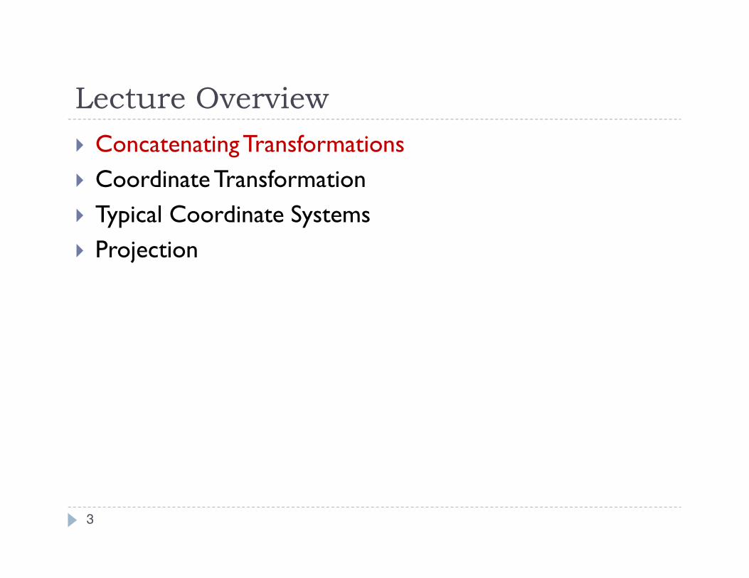
How to rotate around a Pivot Point?
Rotation around
origin:
p’ = R p
Rotation around
pivot point:
p’ = ?
4
Video
� Linear Algebra applied to 3D Graphics
� http://www.youtube.com/watch?v=SMAnlPTmAwE
5
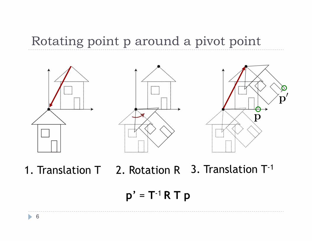
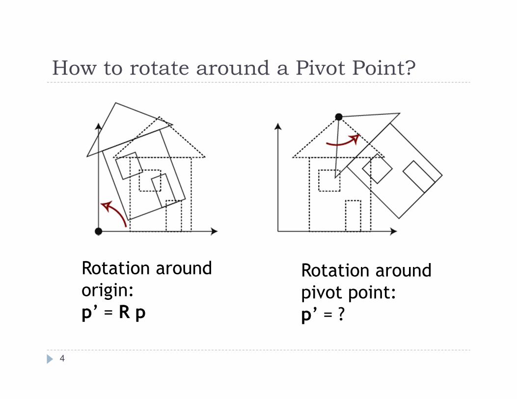
Rotating point p around a pivot point
1. Translation T 2. Rotation R 3. Translation T-1
6
p’ = T-1 R T p
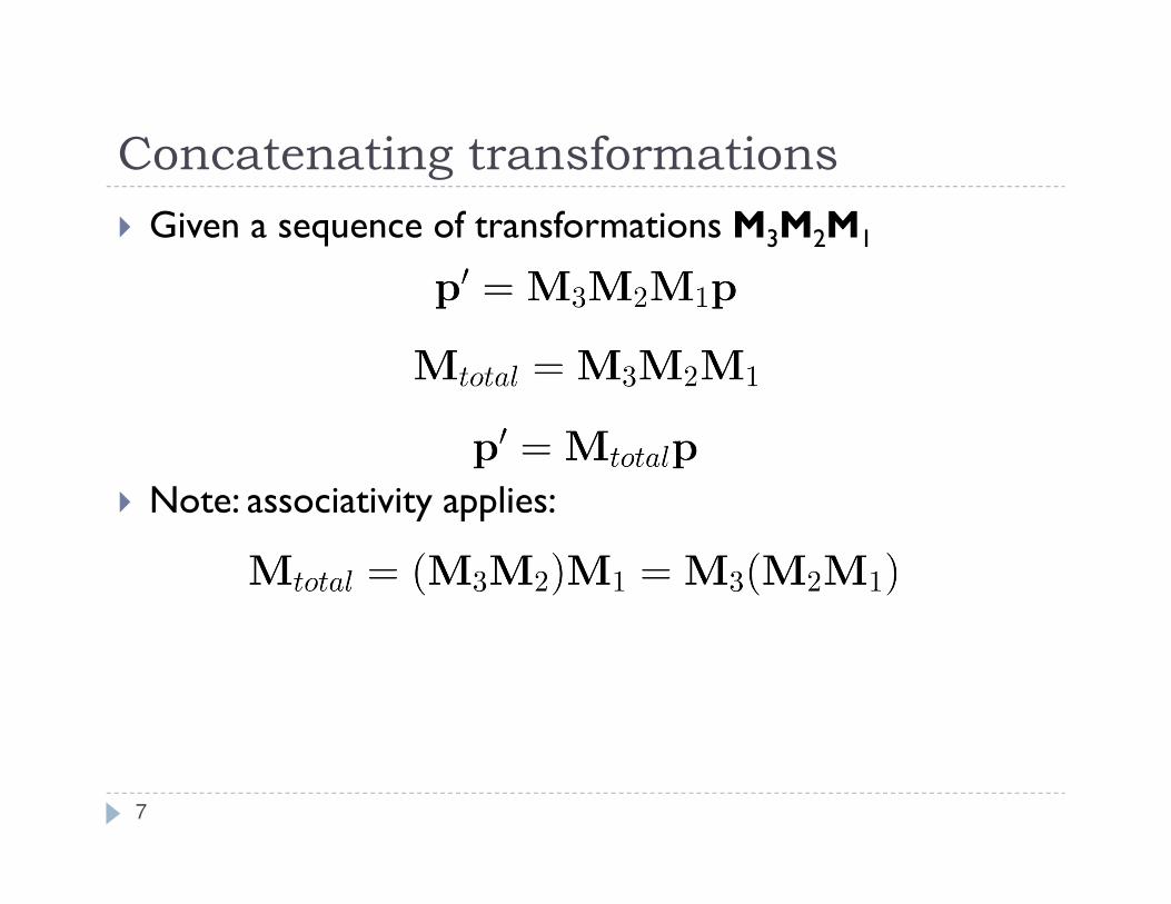
Concatenating transformations
� Given a sequence of transformations M3M2M1
� Note: associativity applies:
7
Lecture Overview
� Concatenating Transformations
� Coordinate Transformation
� Typical Coordinate Systems
� Projection
8
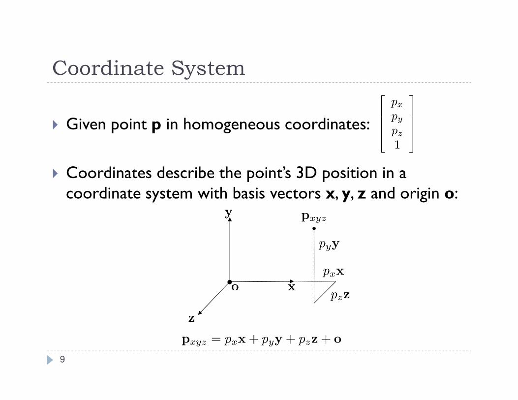
Coordinate System
� Given point p in homogeneous coordinates:
� Coordinates describe the point’s 3D position in a coordinate system with basis vectors x, y, z and origin o:
9
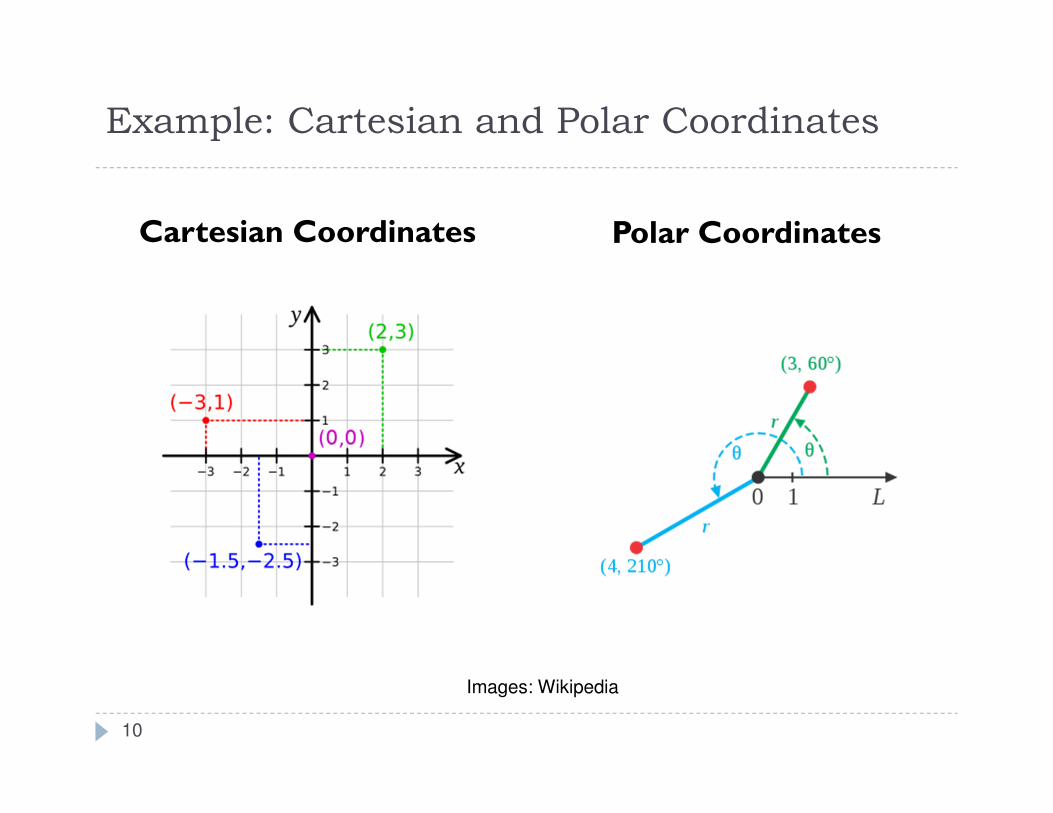
Example: Cartesian and Polar Coordinates
Cartesian Coordinates Polar Coordinates
10
Images: Wikipedia
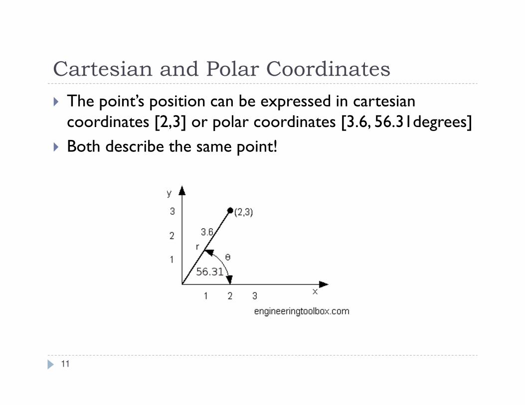
Cartesian and Polar Coordinates
� The point’s position can be expressed in cartesiancoordinates [2,3] or polar coordinates [3.6, 56.31degrees]
� Both describe the same point!
11
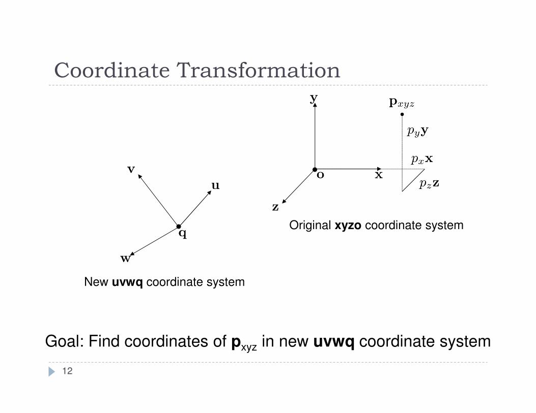
Coordinate Transformation
New uvwq coordinate system
Goal: Find coordinates of pxyz in new uvwq coordinate system
12
Original xyzo coordinate system
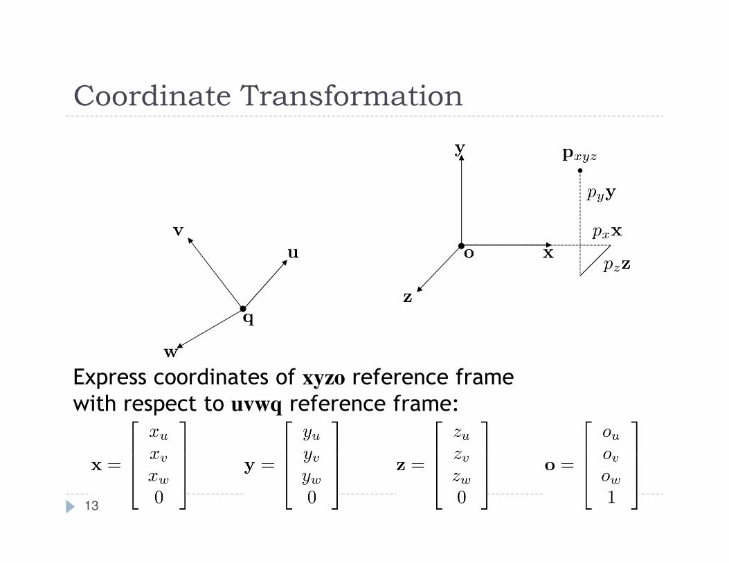
Coordinate Transformation
Express coordinates of xyzo reference frame
with respect to uvwq reference frame:
13
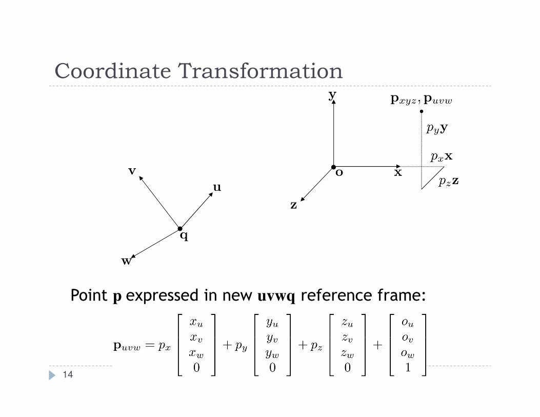
Coordinate Transformation
Point p expressed in new uvwq reference frame:
14
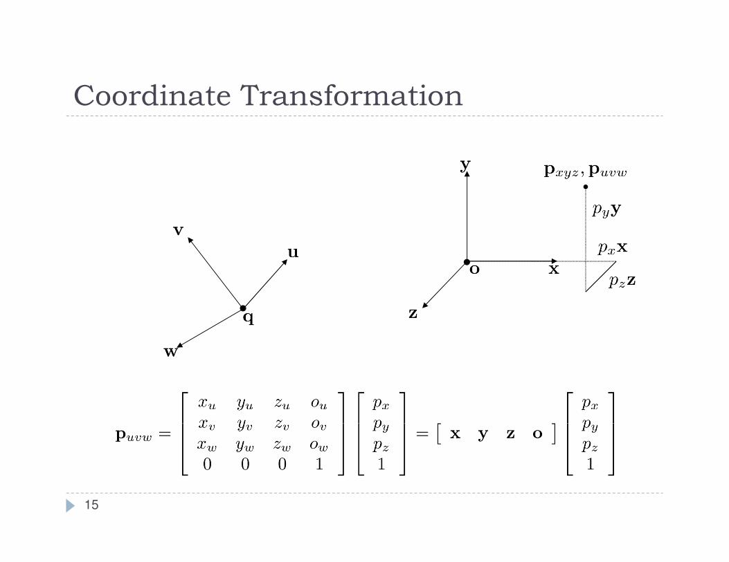
Coordinate Transformation
15
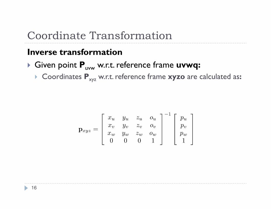
Coordinate Transformation
Inverse transformation
� Given point Puvw w.r.t. reference frame uvwq:
� Coordinates Pxyz w.r.t. reference frame xyzo are calculated as:
16
Lecture Overview
� Concatenating Transformations
� Coordinate Transformation
� Typical Coordinate Systems
� Projection
17
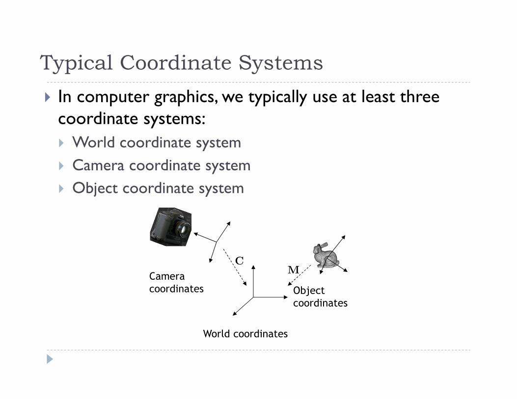
Typical Coordinate Systems
� In computer graphics, we typically use at least three coordinate systems:
� World coordinate system
� Camera coordinate system
� Object coordinate system
World coordinates
Object
coordinates
Camera
coordinates
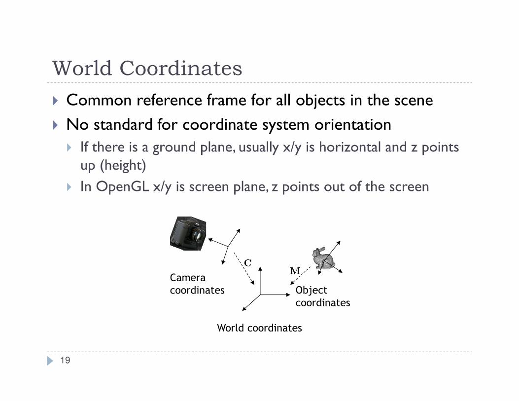
World Coordinates
� Common reference frame for all objects in the scene
� No standard for coordinate system orientation
� If there is a ground plane, usually x/y is horizontal and z points up (height)
� In OpenGL x/y is screen plane, z points out of the screen
World coordinates
Object
coordinates
Camera
coordinates
19
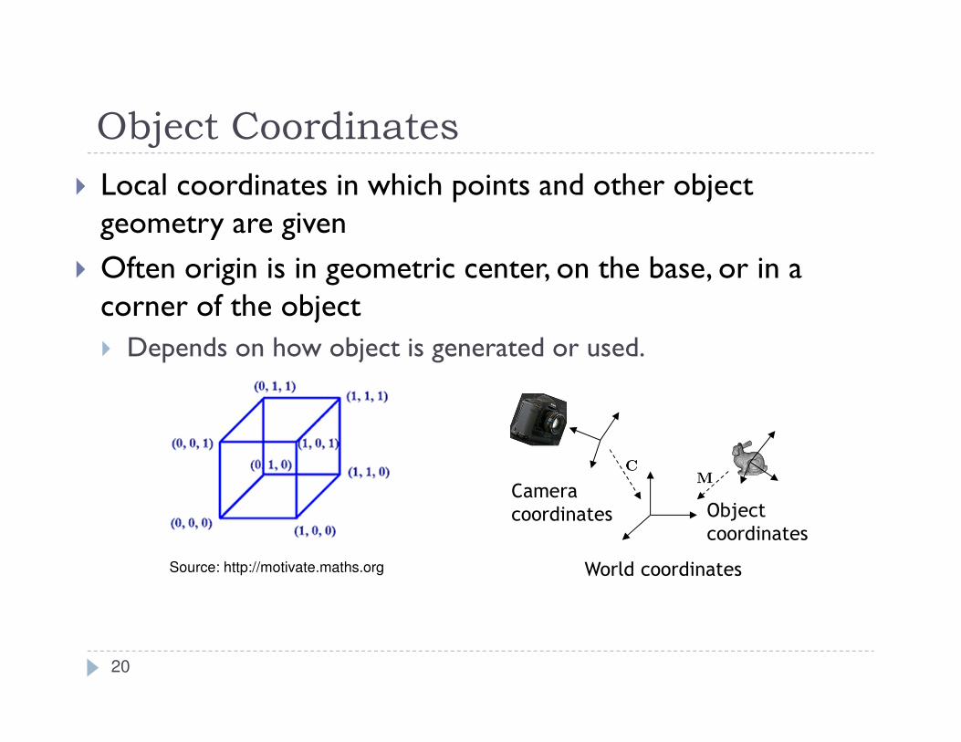
Object Coordinates
� Local coordinates in which points and other object geometry are given
� Often origin is in geometric center, on the base, or in a corner of the object
� Depends on how object is generated or used.
World coordinates
Object
coordinates
Camera
coordinates
20
Source: http://motivate.maths.org
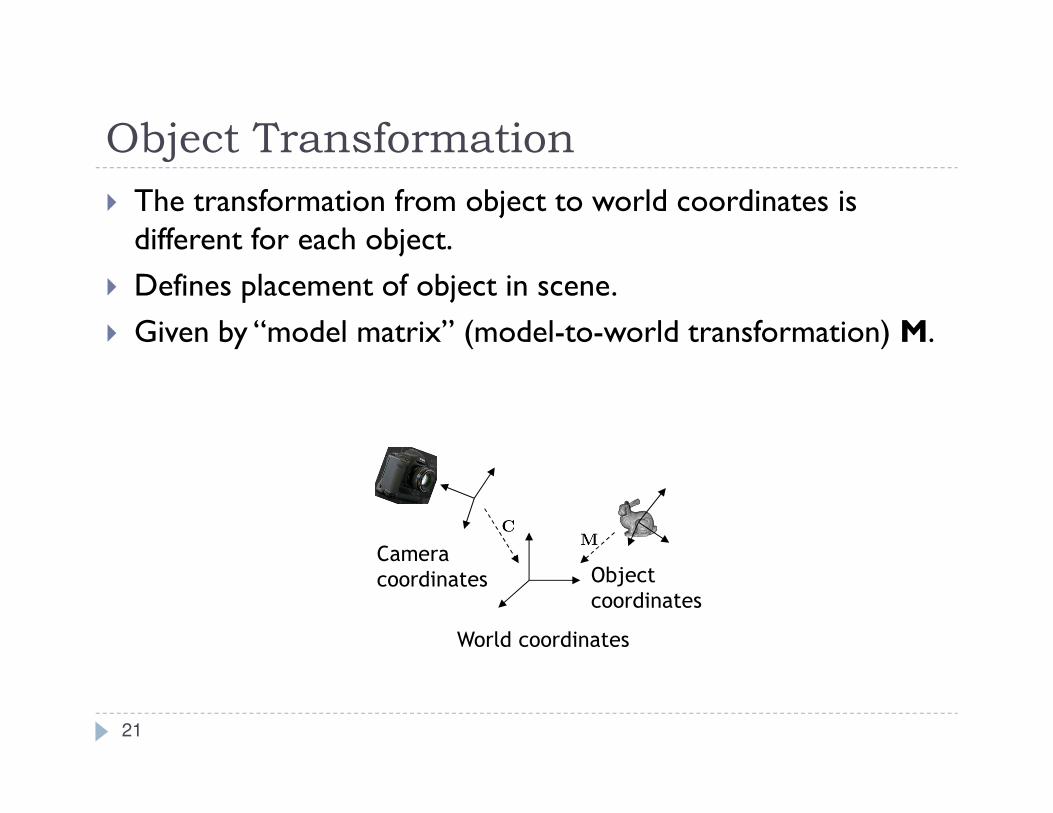
Object Transformation
� The transformation from object to world coordinates is different for each object.
� Defines placement of object in scene.
� Given by “model matrix” (model-to-world transformation) M.
21
World coordinates
Object
coordinates
Camera
coordinates
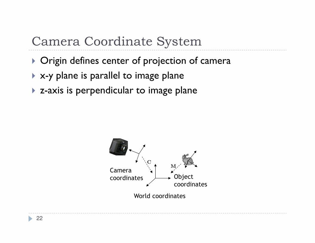
Camera Coordinate System
� Origin defines center of projection of camera
� x-y plane is parallel to image plane
� z-axis is perpendicular to image plane
World coordinates
Object
coordinates
Camera
coordinates
22

Camera Coordinate System
� The Camera Matrix defines the transformation from camera to world coordinates
� Placement of camera in world
World coordinates
Object
coordinates
Camera
coordinates
23

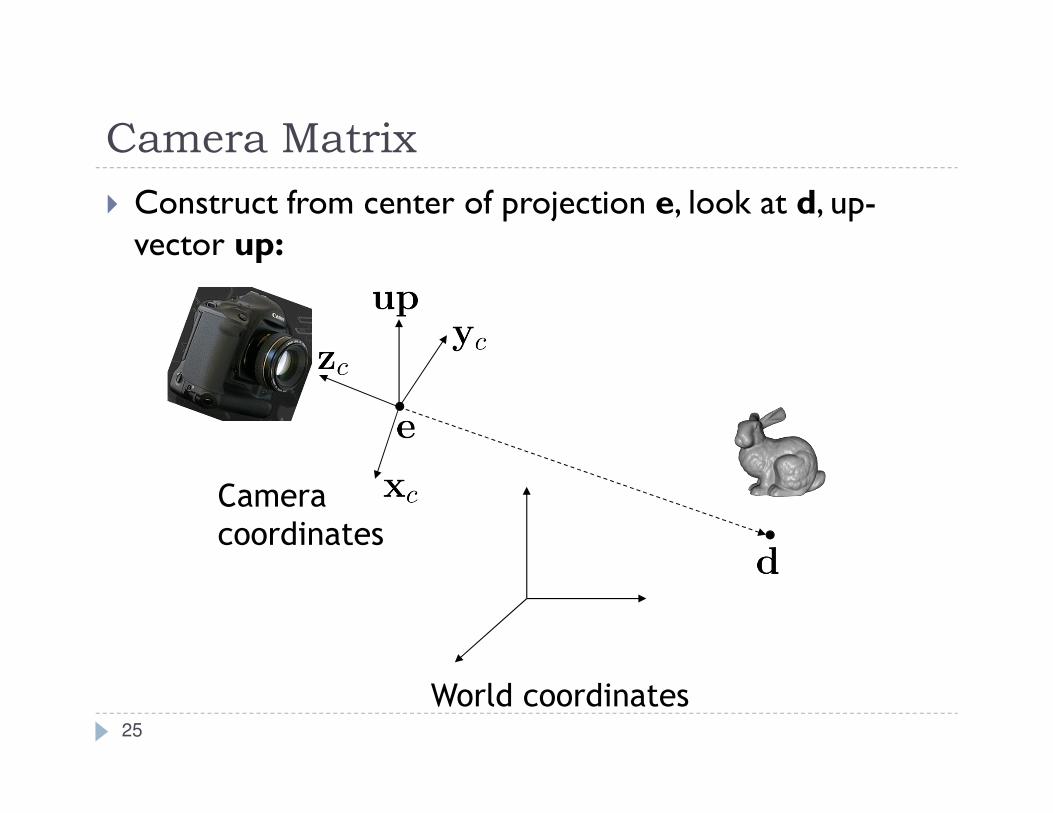
Camera Matrix
� Construct from center of projection e, look at d, up-vector up:
World coordinates
Camera
coordinates
24
Camera Matrix
� Construct from center of projection e, look at d, up-vector up:
World coordinates
Camera
coordinates
25
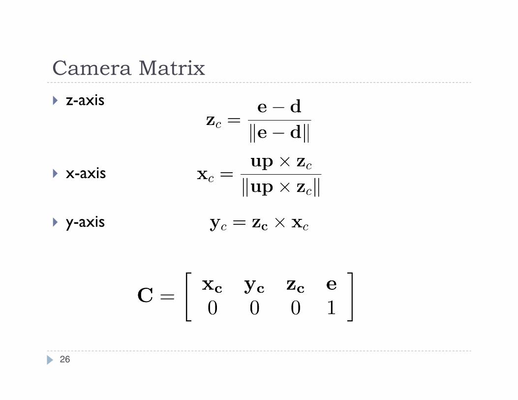
Camera Matrix
� z-axis
� x-axis
� y-axis
26
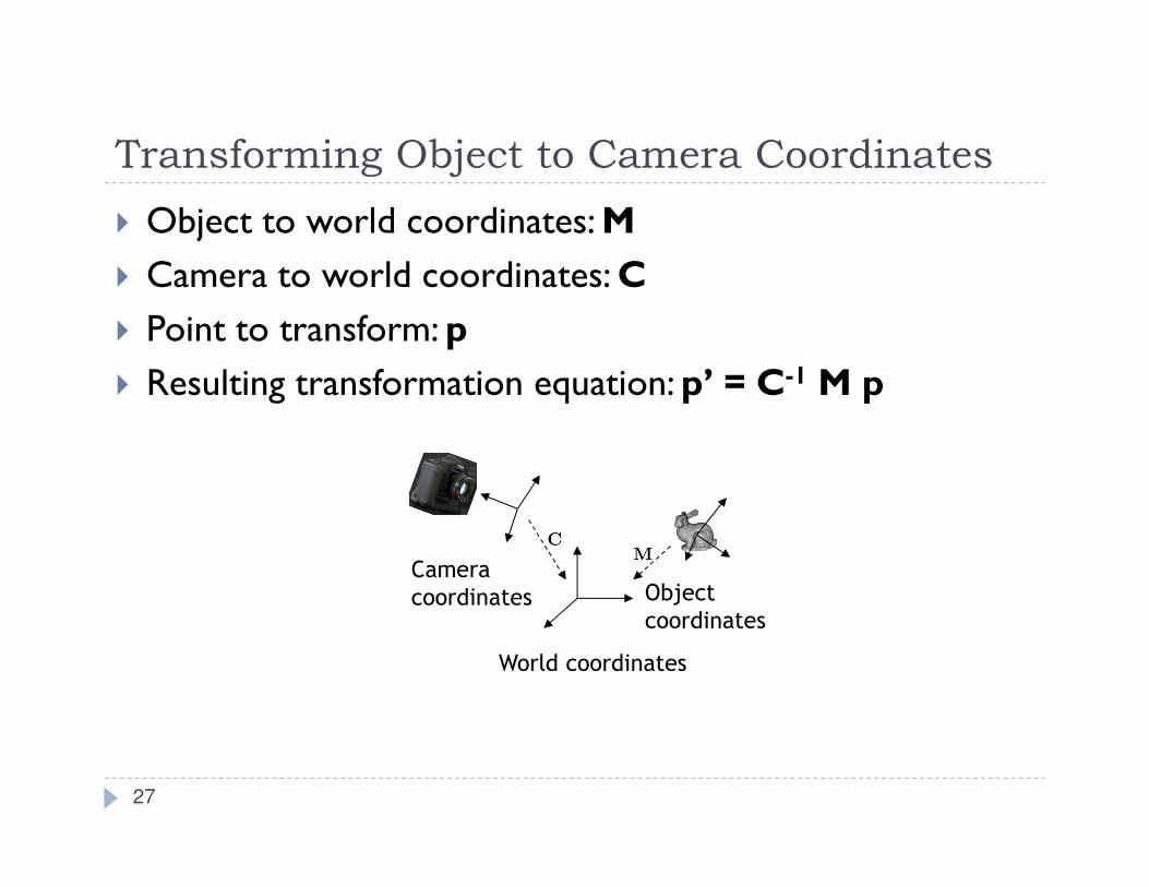
Transforming Object to Camera Coordinates
� Object to world coordinates: M
� Camera to world coordinates: C
� Point to transform: p
� Resulting transformation equation: p’ = C-1 M p
27
World coordinates
Object
coordinates
Camera
coordinates
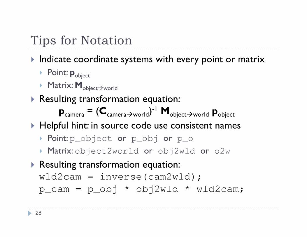
Tips for Notation
� Indicate coordinate systems with every point or matrix
� Point: pobject
� Matrix: Mobject�world
� Resulting transformation equation:pcamera = (Ccamera�world)
-1 Mobject�world pobject
� Helpful hint: in source code use consistent names
� Point: p_object or p_obj or p_o
� Matrix: object2world or obj2wld or o2w
� Resulting transformation equation:wld2cam = inverse(cam2wld);
p_cam = p_obj * obj2wld * wld2cam;
28
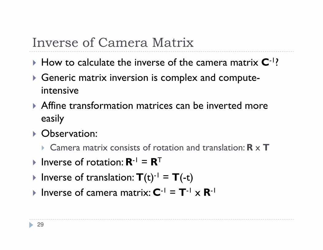
Inverse of Camera Matrix
� How to calculate the inverse of the camera matrix C-1?
� Generic matrix inversion is complex and compute-intensive
� Affine transformation matrices can be inverted more easily
� Observation:
� Camera matrix consists of rotation and translation: R x T
� Inverse of rotation: R-1 = RT
� Inverse of translation: T(t)-1 = T(-t)
� Inverse of camera matrix: C-1 = T-1 x R-1
29
Objects in Camera Coordinates
� We have things lined up the way we like them on screen
� x to the right
� y up
� -z into the screen
� Objects to look at are in front of us, i.e. have negative z values
� But objects are still in 3D
� Next step: project scene to 2D plane
30
Lecture Overview
� Concatenating Transformations
� Coordinate Transformation
� Typical Coordinate Systems
� Projection
31
Projection
� Goal:Given 3D points (vertices) in camera coordinates, determine corresponding image coordinates
� Transforming 3D points into 2D is called Projection
� OpenGL supports two types of projection:
� Orthographic Projection (=Parallel Projection)
� Perspective Projection
32
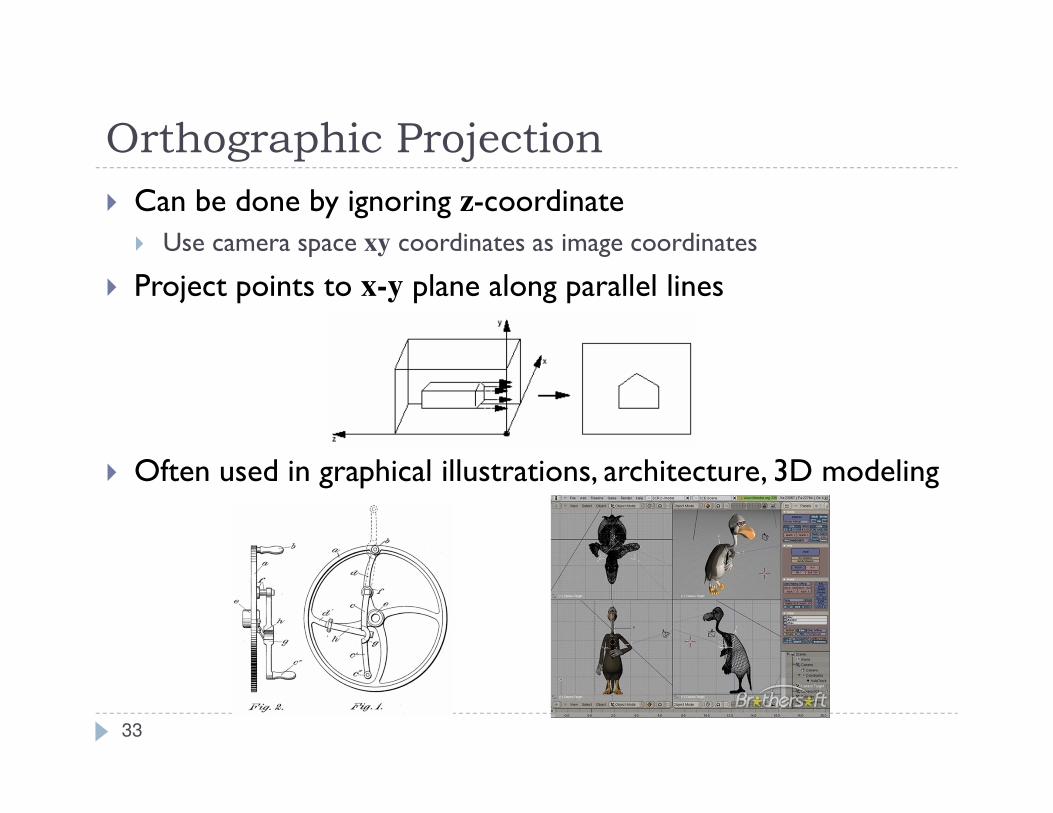
� Can be done by ignoring z-coordinate
� Use camera space xy coordinates as image coordinates
� Project points to x-y plane along parallel lines
� Often used in graphical illustrations, architecture, 3D modeling
Orthographic Projection
33
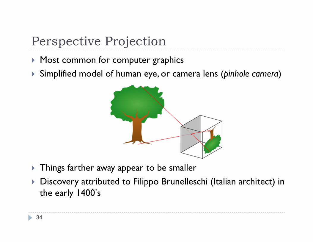
Perspective Projection
� Most common for computer graphics
� Simplified model of human eye, or camera lens (pinhole camera)
� Things farther away appear to be smaller
� Discovery attributed to Filippo Brunelleschi (Italian architect) in the early 1400’s
34
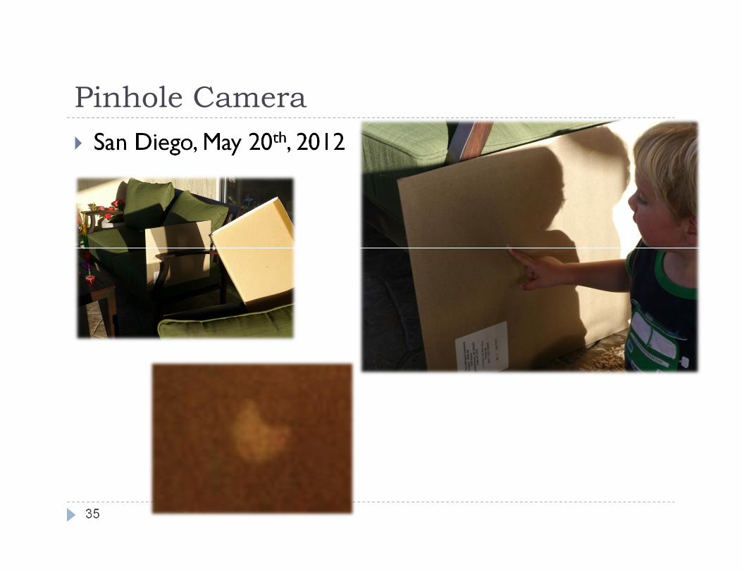
Pinhole Camera
� San Diego, May 20th, 2012
35
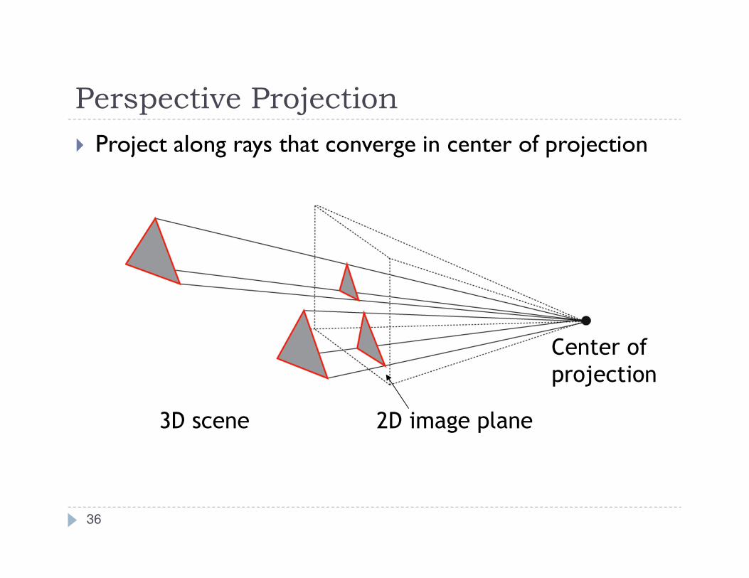
Perspective Projection
� Project along rays that converge in center of projection
2D image plane
Center of
projection
3D scene
36

Perspective Projection
Parallel lines are
no longer parallel,
converge in one point
Earliest example:
La Trinitá (1427) by Masaccio37
Video
� UC Berkeley Professor Ravi Ramamoorthi on Perspective Projection
� http://www.youtube.com/watch?v=VpNJbvZhNCQ
38
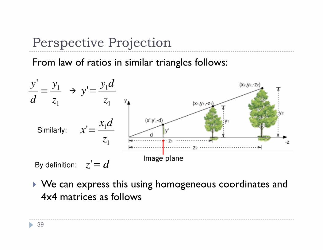
Perspective Projection
From law of ratios in similar triangles follows:
� We can express this using homogeneous coordinates and 4x4 matrices as follows
Image plane
1
1'
z
y
d
y=
1
1'
z
dyy =
dz ='
1
1'
z
dxx =
39
�
Similarly:
By definition:
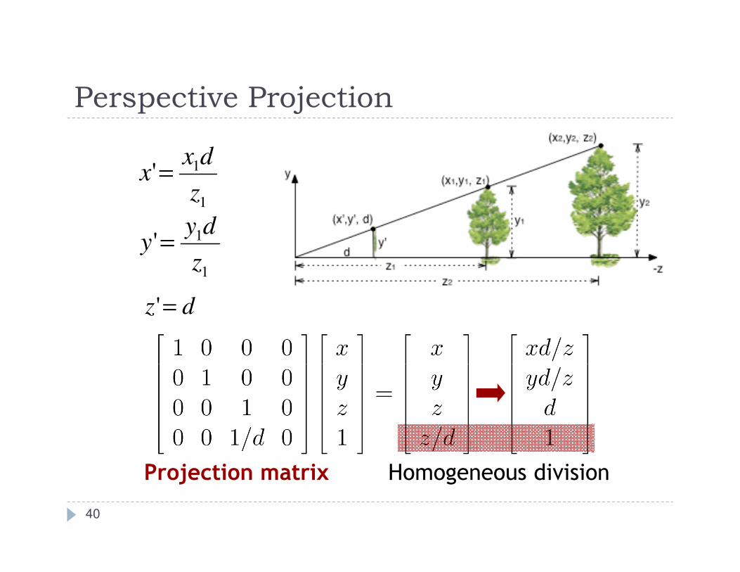
Perspective Projection
Homogeneous divisionProjection matrix
1
1'
z
dyy =
dz ='
1
1'
z
dxx =
40
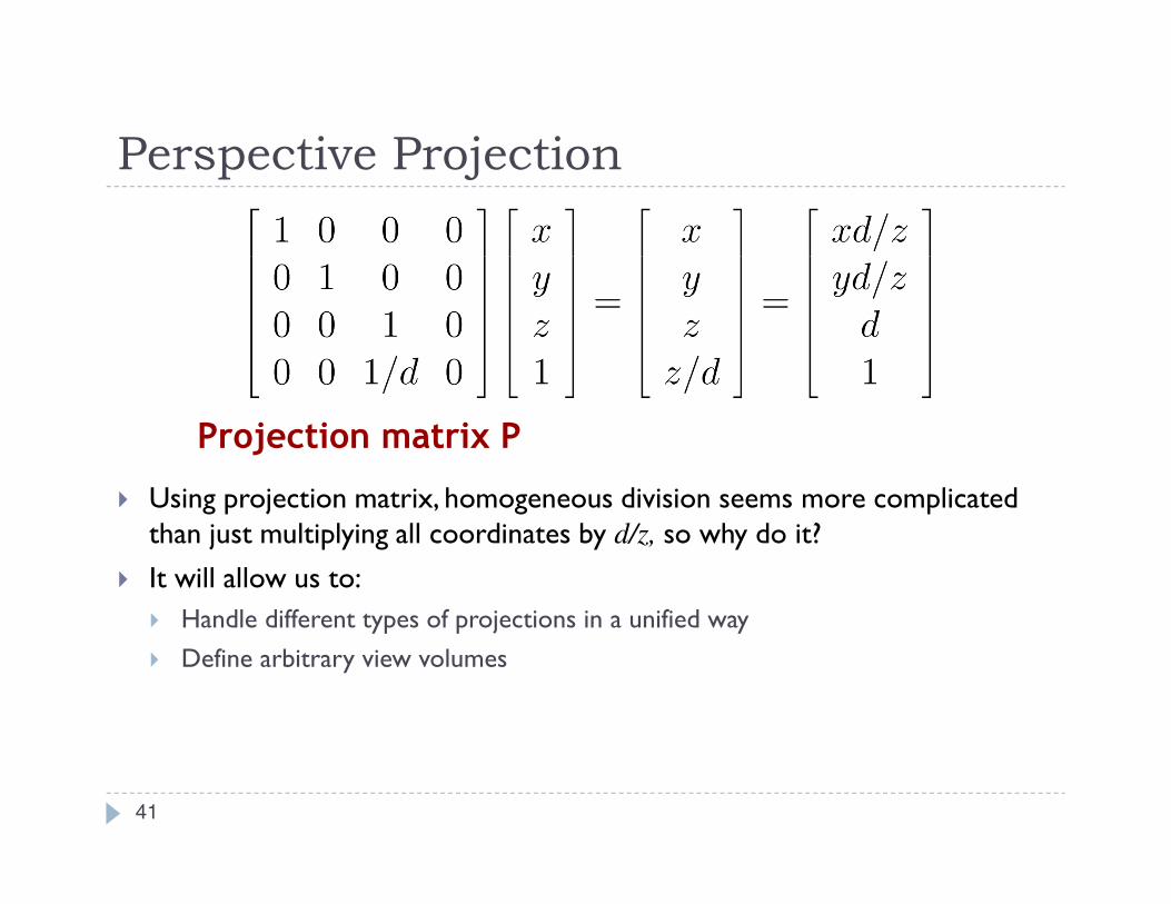
Perspective Projection
� Using projection matrix, homogeneous division seems more complicated than just multiplying all coordinates by d/z, so why do it?
� It will allow us to:
� Handle different types of projections in a unified way
� Define arbitrary view volumes
Projection matrix P
41