Embed Size (px)
Citation preview
CSCE 313: Embedded Systems
Video Out and Image Transformation
Instructor: Jason D. Bakos
Video on DE2 Board
• VGA is a video standard from the late 1980’s
– Uses a 15-pin connector, but only 5 pins are needed at a minimum:
– 3 analog pins: red, green, blue using amplitude modulation
– 2 digital pins: horizontal sync, vertical sync
• DE2-115 has an off-chip video chip
– Mostly just an digital-to-analog converter connected to VGA output
– VGA contains analog reg, green, blue intensity and digital synthronization signals
CSCE 313 2
Video on DE2 Board
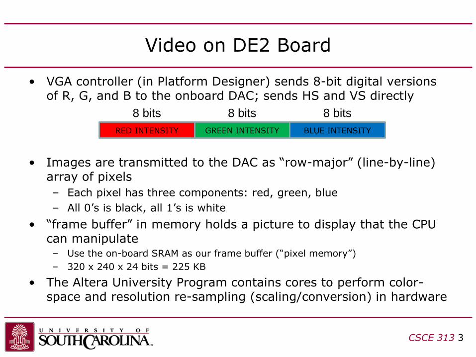
• VGA controller (in Platform Designer) sends 8-bit digital versions of R, G, and B to the onboard DAC; sends HS and VS directly
• Images are transmitted to the DAC as “row-major” (line-by-line) array of pixels
– Each pixel has three components: red, green, blue
– All 0’s is black, all 1’s is white
• “frame buffer” in memory holds a picture to display that the CPU can manipulate– Use the on-board SRAM as our frame buffer (“pixel memory”)
– 320 x 240 x 24 bits = 225 KB
• The Altera University Program contains cores to perform color-space and resolution re-sampling (scaling/conversion) in hardware
CSCE 313 3
RED INTENSITY GREEN INTENSITY BLUE INTENSITY
8 bits 8 bits 8 bits
Video on DE2 Board
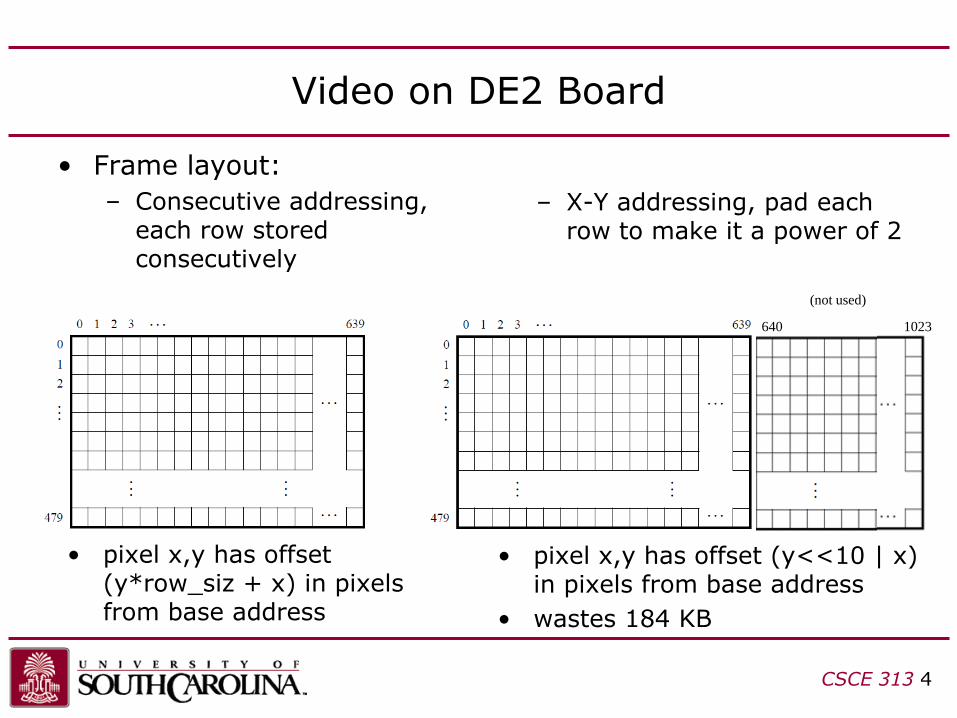
• Frame layout:
– Consecutive addressing, each row stored consecutively
CSCE 313 4
– X-Y addressing, pad each row to make it a power of 2
1023640
(not used)
• pixel x,y has offset (y*row_siz + x) in pixels from base address
• pixel x,y has offset (y<<10 | x) in pixels from base address
• wastes 184 KB
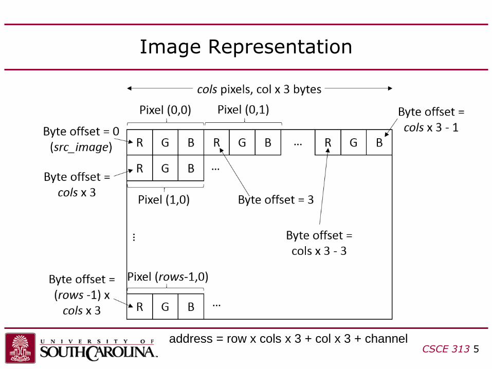
Image Representation
CSCE 313 5address = row x cols x 3 + col x 3 + channel
stream
30 bit
color
640x480
sys_clk
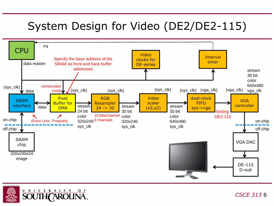
System Design for Video (DE2/DE2-115)
CSCE 313 6
CPU
SRAM interface
data master
data
Pixel Buffer for
DMA
(sys_clk)
RGB Resampler24 -> 30
Video scaler
(x2,x2)data
320x240x24
image
SRAM chip
off-chip
on-chip
stream
24 bit
color
320x240
sys_clk
stream
30 bit
color
320x240
sys_clk
dual-clock FIFO
sys->vga
VGA controller
stream
30 bit
color
640x480
vga_clk
VGA DAC
off-chip
on-chip
DE-115D-sub
consecutive
mode
10 bits/channel
3 channels(From Univ. Program)
Specify the base address of the
SRAM as front and back buffer
addresses
Setting:
DE2-115
(sys_clk) (sys_clk) (sys_clk) (sys_clk) (vga_clk) (vga_clk)
Video clocks for DE-series
Interval timer
irq
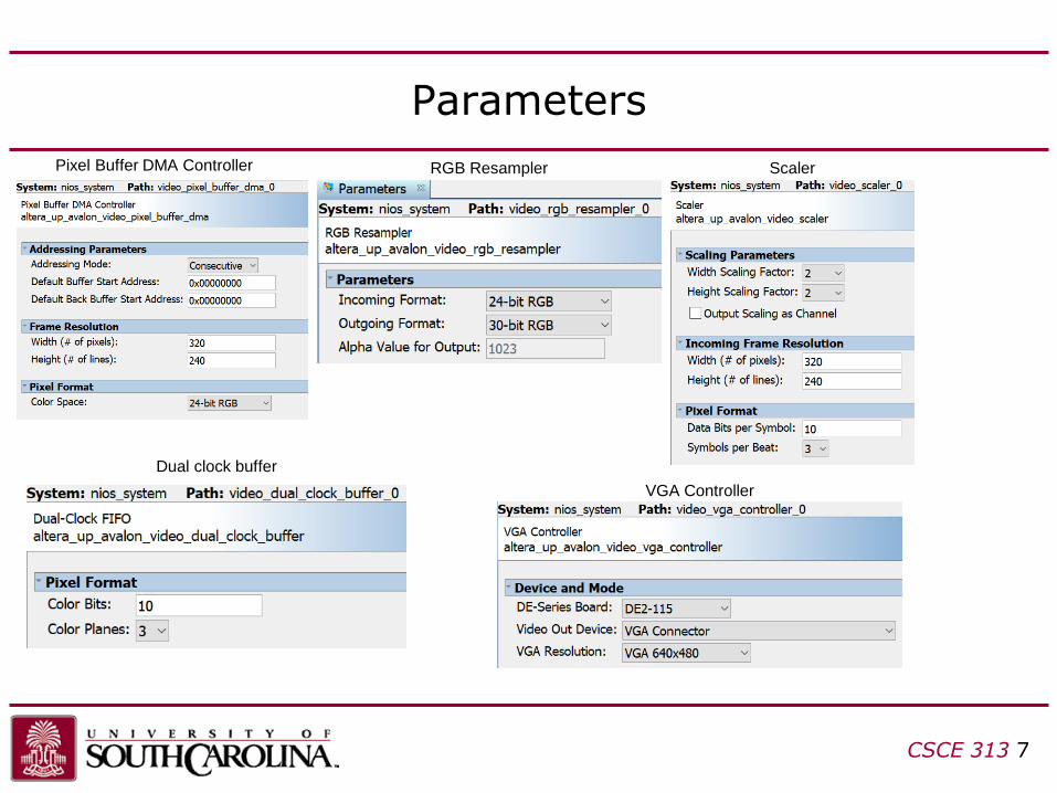
Parameters
CSCE 313 7
Pixel Buffer DMA Controller RGB Resampler Scaler
Dual clock buffer
VGA Controller
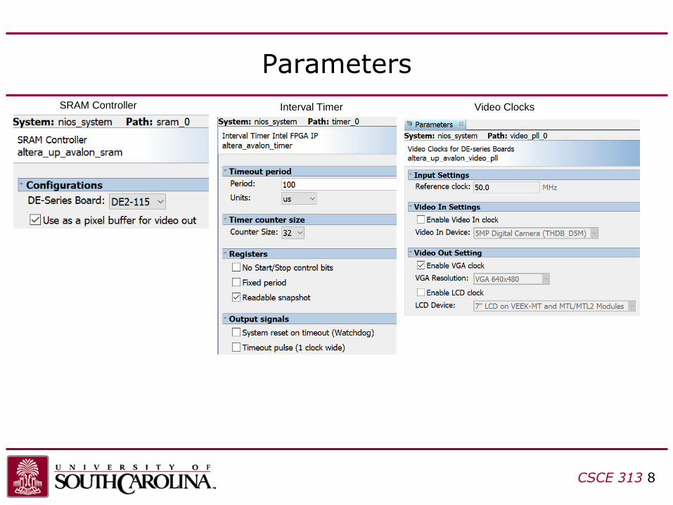
Parameters
CSCE 313 8
SRAM Controller Interval Timer Video Clocks

Verilog Modifications
module lights (input CLOCK_50,
…
output VGA_CLK,
output VGA_HS,
output VGA_VS,
output VGA_BLANK_N,
output VGA_SYNC_N,
output [7:0] VGA_R,
output [7:0] VGA_G,
output [7:0] VGA_B,
inout [15:0] SRAM_DQ,
output [19:0] SRAM_ADDR,
output SRAM_LB_N,
output SRAM_UB_N,
output SRAM_CE_N,
output SRAM_OE_N,
output SRAM_WE_N);
CSCE 313 9

Verilog Modifications
nios_system u0 (
.clk_clk (CLOCK_50), // clk.clk
…
.vga_CLK (VGA_CLK), // vga.CLK
.vga_HS (VGA_HS), // .HS
.vga_VS (VGA_VS), // .VS
.vga_BLANK (VGA_BLANK_N), // .BLANK
.vga_SYNC (VGA_SYNC_N), // .SYNC
.vga_R (VGA_R), // .R
.vga_G (VGA_G), // .G
.vga_B (VGA_B), // .B
.sram_DQ (SRAM_DQ), // sram.DQ
.sram_ADDR (SRAM_ADDR), // .ADDR
.sram_LB_N (SRAM_LB_N), // .LB_N
.sram_UB_N (SRAM_UB_N), // .UB_N
.sram_CE_N (SRAM_CE_N), // .CE_N
.sram_OE_N (SRAM_OE_N), // .OE_N
.sram_WE_N (SRAM_WE_N) // .WE_N
);
CSCE 313 10

Copying Image to RO File System
• To load an image into the DE2, I wrote a Matlab script that can:
– read image file
– add a border around the image if aspect ratio <> 4/3
– save into a C source code file (global constant array myimage)
• To use it:
– download it from Dropbox
– open MATLAB (command: “octave”)
– change current folder to where you downloaded it
– type: convert_image_to_c_file(‘<filename>');• You may use my image, lumcat.jpg or use your own
– this will generate myfile.c and myfile.h
– Add to makefile:• From app directory (e.g. lights/software/lights):
– nios2-app-update-makefile --add-src-files myfile.c --app-dir .
CSCE 313 11
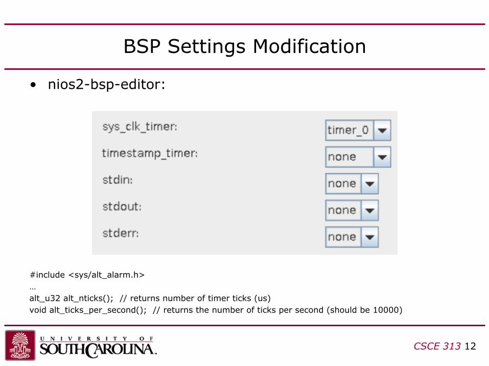
BSP Settings Modification
• nios2-bsp-editor:
#include <sys/alt_alarm.h>
…
alt_u32 alt_nticks(); // returns number of timer ticks (us)
void alt_ticks_per_second(); // returns the number of ticks per second (should be 10000)
CSCE 313 12
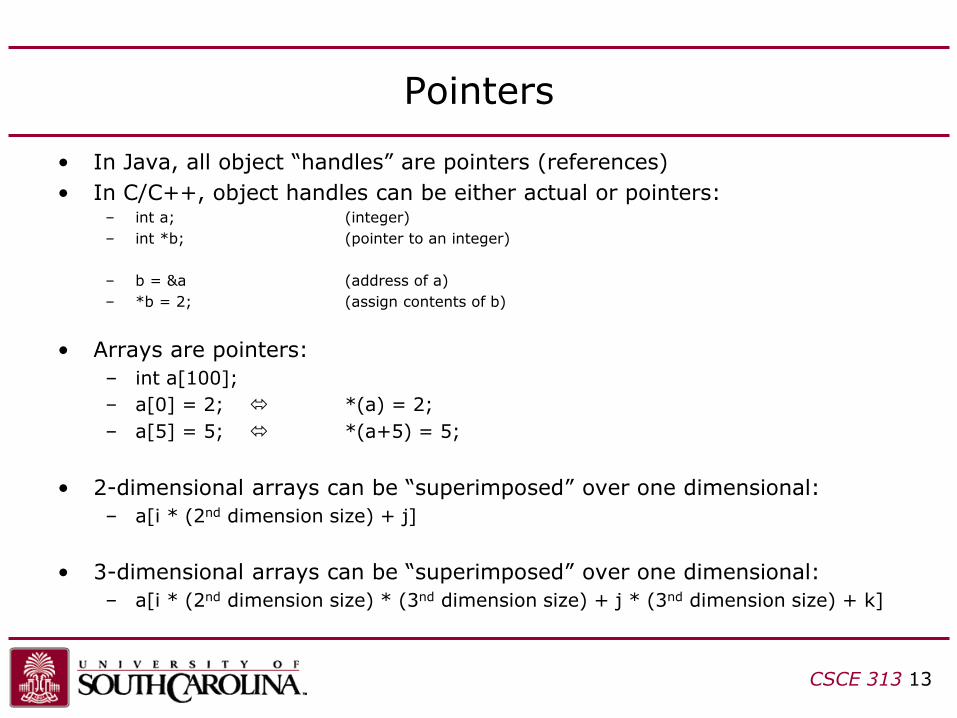
Pointers
• In Java, all object “handles” are pointers (references)
• In C/C++, object handles can be either actual or pointers:– int a; (integer)
– int *b; (pointer to an integer)
– b = &a (address of a)
– *b = 2; (assign contents of b)
• Arrays are pointers:
– int a[100];
– a[0] = 2; *(a) = 2;
– a[5] = 5; *(a+5) = 5;
• 2-dimensional arrays can be “superimposed” over one dimensional:
– a[i * (2nd dimension size) + j]
• 3-dimensional arrays can be “superimposed” over one dimensional:
– a[i * (2nd dimension size) * (3nd dimension size) + j * (3nd dimension size) + k]
CSCE 313 13
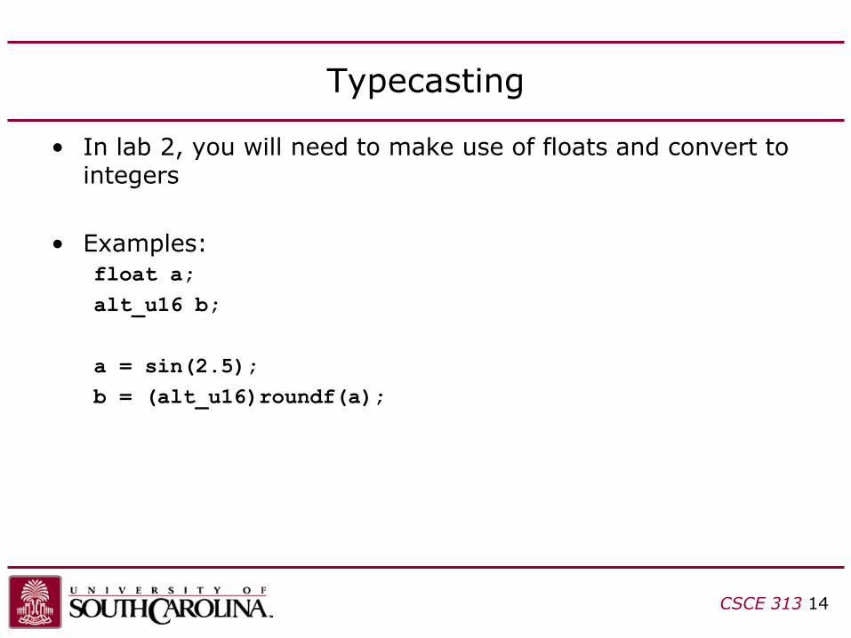
Typecasting
• In lab 2, you will need to make use of floats and convert to integers
• Examples:
float a;
alt_u16 b;
a = sin(2.5);
b = (alt_u16)roundf(a);
CSCE 313 14

Accessing the Source Image
• We’re using consecutive mode for the pixel memory, so pixels are stored consecutively
• Each pixel is 3-byte value
• To access pixel at row=100, col=200:– my_image[100*320*3+200*3+0] (red)
– my_image[100*320*3+200*3+1] (green)
– my_image[100*320*3+200*3+2] (blue)
CSCE 313 15
RED GREEN BLUE
23 16 15 8 7 0
row 0, 320 pixels row 1, 320 pixels row 2, 320 pixels row 239, 320 pixels…
low addresses high addresses
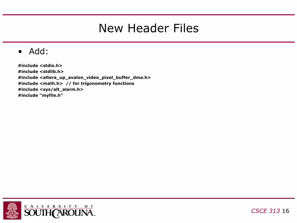
New Header Files
• Add:
#include <stdio.h>
#include <stdlib.h>
#include <altera_up_avalon_video_pixel_buffer_dma.h>
#include <math.h> // for trigonometry functions
#include <sys/alt_alarm.h>
#include "myfile.h"
CSCE 313 16
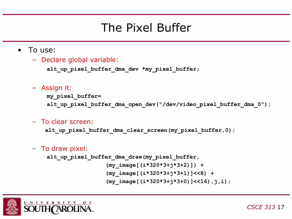
The Pixel Buffer
• To use:
– Declare global variable:
alt_up_pixel_buffer_dma_dev *my_pixel_buffer;
– Assign it:my_pixel_buffer=
alt_up_pixel_buffer_dma_open_dev("/dev/video_pixel_buffer_dma_0");
– To clear screen:
alt_up_pixel_buffer_dma_clear_screen(my_pixel_buffer,0);
– To draw pixel:alt_up_pixel_buffer_dma_draw(my_pixel_buffer,
(my_image[(i*320*3+j*3+2)]) +
(my_image[(i*320*3+j*3+1)]<<8) +
(my_image[(i*320*3+j*3+0)]<<16),j,i);
CSCE 313 17
Image Transformation Matrices
• Simple image transformation matrix can be used to…
– rotate, scale, shear, reflect, and orthogonal projection
• For Lab 2, we want to perform rotation and scaling
• The matrices we use are 2x2 and used to determine how to move each pixel from the original image to the new image in order to perform the transformation
• Consider:
– source pixels (row,col) of original image
– destination pixels (row’,col’) of transformed image
CSCE 313 18
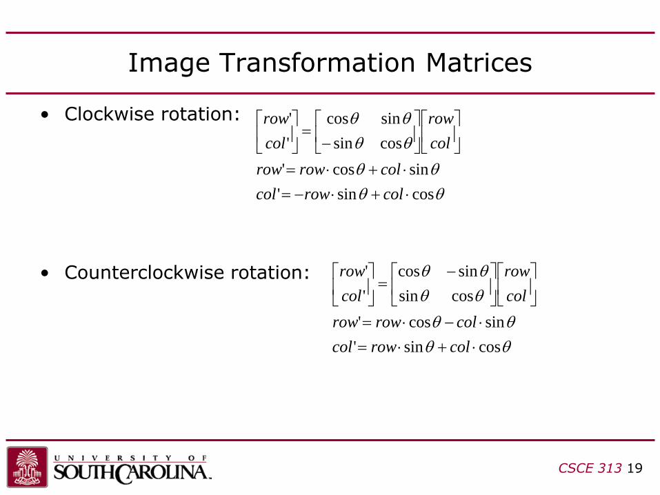
Image Transformation Matrices
• Clockwise rotation:
• Counterclockwise rotation:
CSCE 313 19
cossin'
sincos'
cossin
sincos
'
'
+−=
+=
−=
colrowcol
colrowrow
col
row
col
row
cossin'
sincos'
cossin
sincos
'
'
+=
−=
−=
colrowcol
colrowrow
col
row
col
row
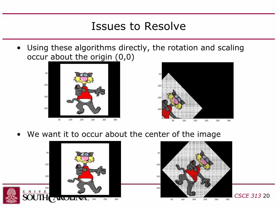
Issues to Resolve
• Using these algorithms directly, the rotation and scaling occur about the origin (0,0)
• We want it to occur about the center of the image
CSCE 313 20
50 100 150 200 250 300
50
100
150
200
50 100 150 200 250 300
50
100
150
200
50 100 150 200 250 300
50
100
150
200
50 100 150 200 250 300
50
100
150
200
Issues to Resolve
• To fix this:
– subtract 320/2 from the column
– subtract 240/2 from the row
…before you multiply against the transformation matrix, then add these values back after your multiply
CSCE 313 21

Issues to Resolve
• Second problem: pixels aliasing to same location, causing unfilled pixels in destination image
CSCE 313 22
20 40 60 80 100 120 140
20
40
60
80
100
120
140
160

Issues to Resolve
• To solve this, iterate over all destination image pixels and calculate reverse transform
– Counterclockwise rotation
CSCE 313 23
20 40 60 80 100 120 140 160 180 200
20
40
60
80
100
120
140
160
180
200
220
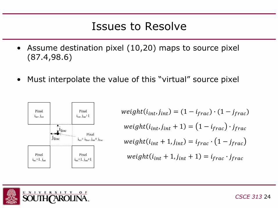
Issues to Resolve
• Assume destination pixel (10,20) maps to source pixel (87.4,98.6)
• Must interpolate the value of this “virtual” source pixel
CSCE 313 24
𝑤𝑒𝑖𝑔ℎ𝑡 𝑖𝑖𝑛𝑡, 𝑗𝑖𝑛𝑡 = (1 − 𝑖𝑓𝑟𝑎𝑐) ∙ (1 − 𝑗𝑓𝑟𝑎𝑐)
𝑤𝑒𝑖𝑔ℎ𝑡 𝑖𝑖𝑛𝑡, 𝑗𝑖𝑛𝑡 + 1 = 1 − 𝑖𝑓𝑟𝑎𝑐 ∙ 𝑗𝑓𝑟𝑎𝑐
𝑤𝑒𝑖𝑔ℎ𝑡 𝑖𝑖𝑛𝑡 + 1, 𝑗𝑖𝑛𝑡 = 𝑖𝑓𝑟𝑎𝑐 ∙ 1 − 𝑗𝑓𝑟𝑎𝑐
𝑤𝑒𝑖𝑔ℎ𝑡 𝑖𝑖𝑛𝑡 + 1, 𝑗𝑖𝑛𝑡 + 1 = 𝑖𝑓𝑟𝑎𝑐 ∙ 𝑗𝑓𝑟𝑎𝑐
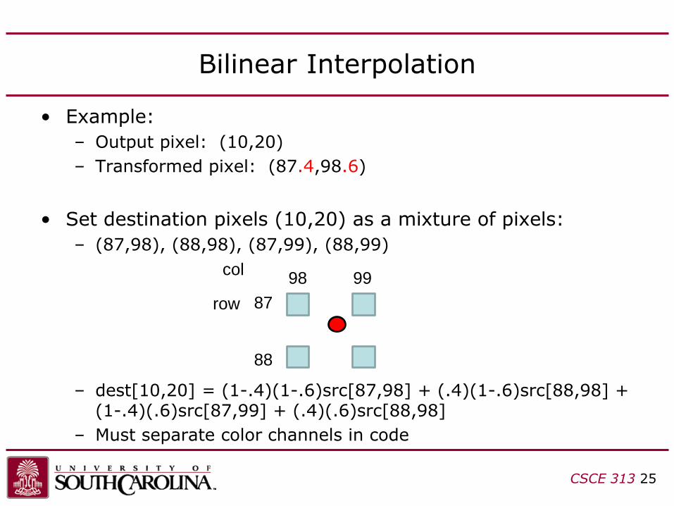
• Example:
– Output pixel: (10,20)
– Transformed pixel: (87.4,98.6)
• Set destination pixels (10,20) as a mixture of pixels:
– (87,98), (88,98), (87,99), (88,99)
– dest[10,20] = (1-.4)(1-.6)src[87,98] + (.4)(1-.6)src[88,98] + (1-.4)(.6)src[87,99] + (.4)(.6)src[88,98]
– Must separate color channels in code
Bilinear Interpolation
CSCE 313 25
87
88
row
col98 99
Issues to Resolve
• Make sure you…
– use rounding and type casting for the transformation matrix (float and alt_u16)
– disregard output coordinates that fall outside the frame
– always transform against the original image
– initialize the output image to black before transforming
CSCE 313 26