Embed Size (px)
Citation preview
1
CSCD 330Network Programming Winter 2014
Lecture 15Network LayerIP Addressing
Reading: Chapter 4
Some slides provided courtesy of J.F Kurose and K.W. Ross, All Rights Reserved, copyright 1996-2007

2
Network Layer
• 4. 1 Introduction
• 4.2 Virtual circuit and datagram networks
• 4.3 What’s inside a router
• 4.4 IP: Internet Protocol• Datagram format
• Fragmentation
• IPv4 addressing
• 4.5 Routing algorithms• Link state• Distance Vector• Hierarchical routing
• 4.6 Routing in the Internet
• RIP• OSPF• BGP
• 4.7 Broadcast and multicast routing
Introduction
• Last time, began the network layer• Provides a best effort service most of the time• Alternate model, ATM, Frame-relay tries to
create a virtual circuit on top of the best effort datagram environment
• Talked about router functions• Today, get into addressing …
3
IP Version 4 Header
• IPv4 Frame Header• Designed to handle addressing and routing challenges• Think about trying to route through a network where …
• Physical network varies – different capacity of links• Maximize efficiency – means minimize redundancy• Account for both uncertain and certain delivery• Handle errors
• Explains the IP packet header …
4
IPv4 Header
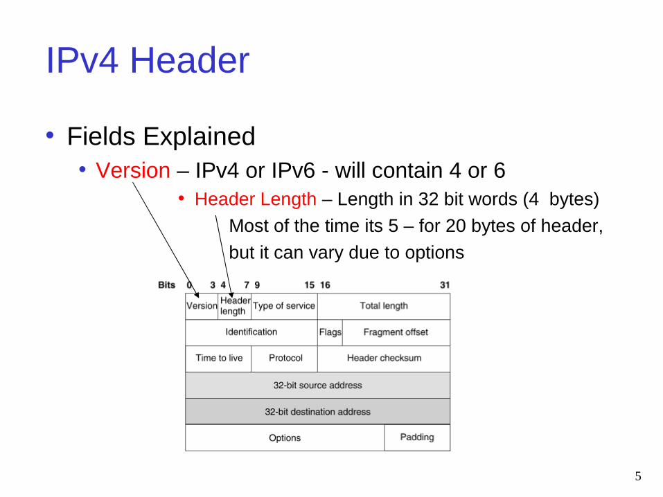
• Fields Explained• Version – IPv4 or IPv6 - will contain 4 or 6
• Header Length – Length in 32 bit words (4 bytes)
Most of the time its 5 – for 20 bytes of header,
but it can vary due to options
5
IPv4 Header
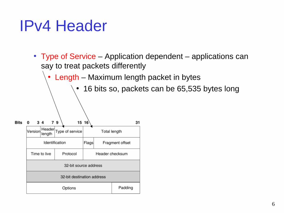
• Type of Service – Application dependent – applications can say to treat packets differently
• Length – Maximum length packet in bytes• 16 bits so, packets can be 65,535 bytes long
6

IPv4 Header• Time to Live (TTL) – Used to be a time, now its more a hop
count – don’t want packets circulating through network forever - Routers decrease this by 1, default 64
• Protocol – Upper layer protocol, TCP or UDP or ICMP
• Checksum – Only of the IP Header!
Computed by adding header as 16 bit words using ones complement arithmetic and then taking the one’s complement of the result, Routers compute it too.
At destination, compare it to value stored in this field and if different discard the packet
Line Two Deals with Fragments
Fragment offset – 13 bits, in bytes/8
Fragment Identification – 16 bits, identifier
set by sender
Flags – 3 bits, indicates fragments7

IPv4 Header
• Source Address 32 bits long• Destination Address 32 bits long
Gives us 232 addresses or
over 4 billion addresses• Options field – used sometimes
8
Fragmentation
• One design decision helped Internet remain flexible • Able to accommodate multiple network
technologies – Packet Fragmentation• Packets can be divided so can pass through links
of different sizes• Some typical maximum packet sizes
• Ethernet – 1500 bytes long• FDDI – 4500 bytes long• Point to point (PPP) – 532 bytes long
9
Fragmentation
• Every network sets its MTU • Maximum Transmission Unit
• Largest Frame Size of Data link layer• Previous slides shows -> MTU varies with link type
• IP packets need to adjust to that frame size• Think of squeezing packets through different sized pipes• If MTU along the way, is smaller than IP packet size on
your network
• Datagram must fit within payload of link layer frame so …
• Fragmentation occurs in router – when datagram size > than network MTU it must travel over
10
Example Fragmentation Links
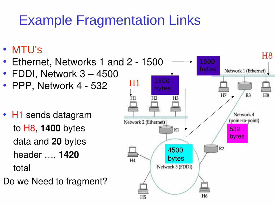
• MTU's• Ethernet, Networks 1 and 2 - 1500• FDDI, Network 3 – 4500• PPP, Network 4 - 532
• H1 sends datagram to H8, 1400 bytes data and 20 bytes header …. 1420 totalDo we Need to fragment?
11
4500 bytes
532 bytes
1500 bytes
H1
H8
1500 bytes
Fragmentation: Example Network
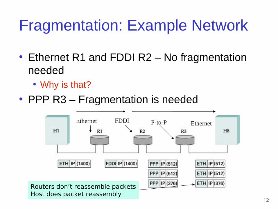
• Ethernet R1 and FDDI R2 – No fragmentation needed• Why is that?
• PPP R3 – Fragmentation is needed
12
Routers don’t reassemble packetsHost does packet reassembly
Ethernet FDDI P-to-P Ethernet
13
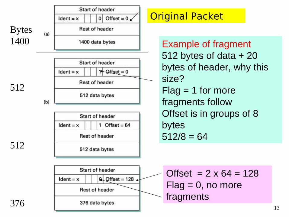
Example of fragment512 bytes of data + 20 bytes of header, why this size?Flag = 1 for more fragments followOffset is in groups of 8 bytes512/8 = 64
Offset = 2 x 64 = 128Flag = 0, no more fragments
Original Packet Bytes1400
512
512
376
Fragments Reassembly
• IF all fragments don’t arrive, • What do you do?• Discards ones that have arrived• Packet will need to be resent• Consequently, fragments can waste resources
• Not recommended !!!• Hosts encouraged to perform MTU path
discovery• Avoid fragments if possible
14
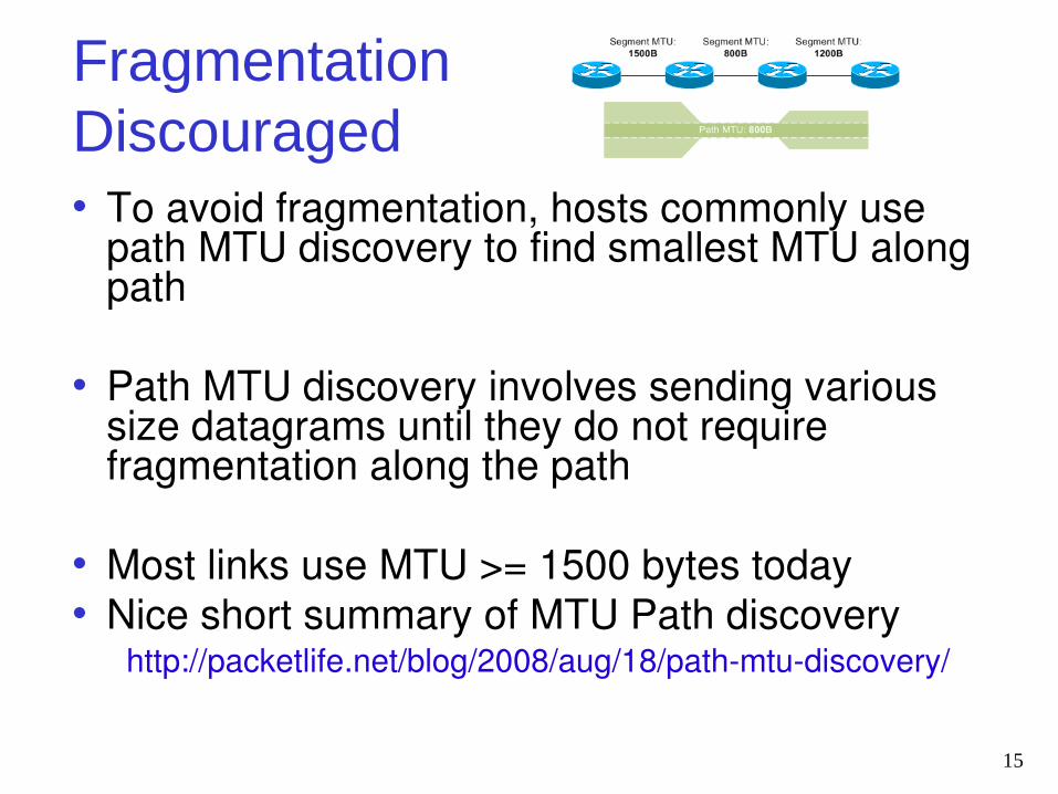
Fragmentation Discouraged• To avoid fragmentation, hosts commonly use
path MTU discovery to find smallest MTU along path
• Path MTU discovery involves sending various size datagrams until they do not require fragmentation along the path
• Most links use MTU >= 1500 bytes today • Nice short summary of MTU Path discovery http://packetlife.net/blog/2008/aug/18/path-mtu-discovery/
15
Network Addressing
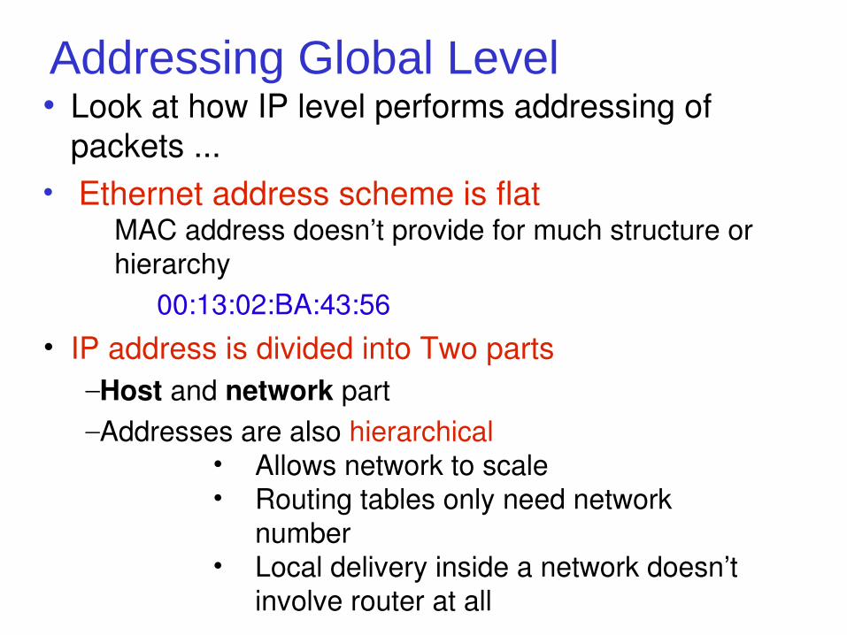
Addressing Global Level• Look at how IP level performs addressing of
packets ...• Ethernet address scheme is flat MAC address doesn’t provide for much structure or hierarchy
00:13:02:BA:43:56• IP address is divided into Two parts
–Host and network part–Addresses are also hierarchical
• Allows network to scale• Routing tables only need network
number• Local delivery inside a network doesn’t
involve router at all
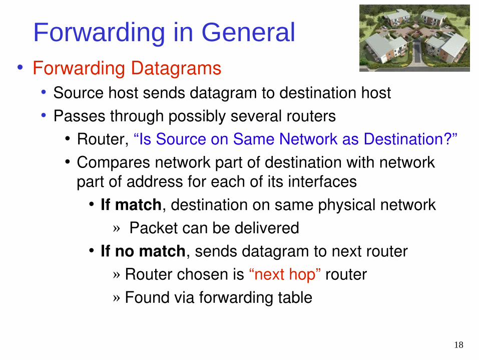
Forwarding in General• Forwarding Datagrams
• Source host sends datagram to destination host• Passes through possibly several routers
• Router, “Is Source on Same Network as Destination?”• Compares network part of destination with network
part of address for each of its interfaces• If match, destination on same physical network
» Packet can be delivered• If no match, sends datagram to next router
» Router chosen is “next hop” router » Found via forwarding table
18

IP Addresses
19
IP Addressing An Evolution
• IP Addresses and Grouping together to form networks• Didn’t happen by accident• Evolving process• First attempt
• Divide addresses into rigid categories• Then, more flexible way of addressing
•Subnetting • Still working on it … IPV6 is in the works
20
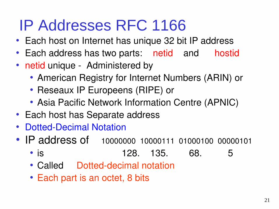
IP Addresses RFC 1166• Each host on Internet has unique 32 bit IP address• Each address has two parts: netid and hostid• netid unique - Administered by
• American Registry for Internet Numbers (ARIN) or• Reseaux IP Europeens (RIPE) or• Asia Pacific Network Information Centre (APNIC)
• Each host has Separate address • Dotted-Decimal Notation• IP address of 10000000 10000111 01000100 00000101
• is 128. 135. 68. 5• Called Dotted-decimal notation• Each part is an octet, 8 bits
21
Classful Addressing
• Classful addressing, formally adopted as part of the Internet Protocol (IP) in RFC 791, 1981• Internet's first major addressing scheme
• There were three address classes to chose from:• A, B, or C, corresponding to 8-bit, 16-bit, or 24-bit
network prefixes• No other prefix lengths were allowed• Not very flexible to needs of organizations
22
Classful Addresses
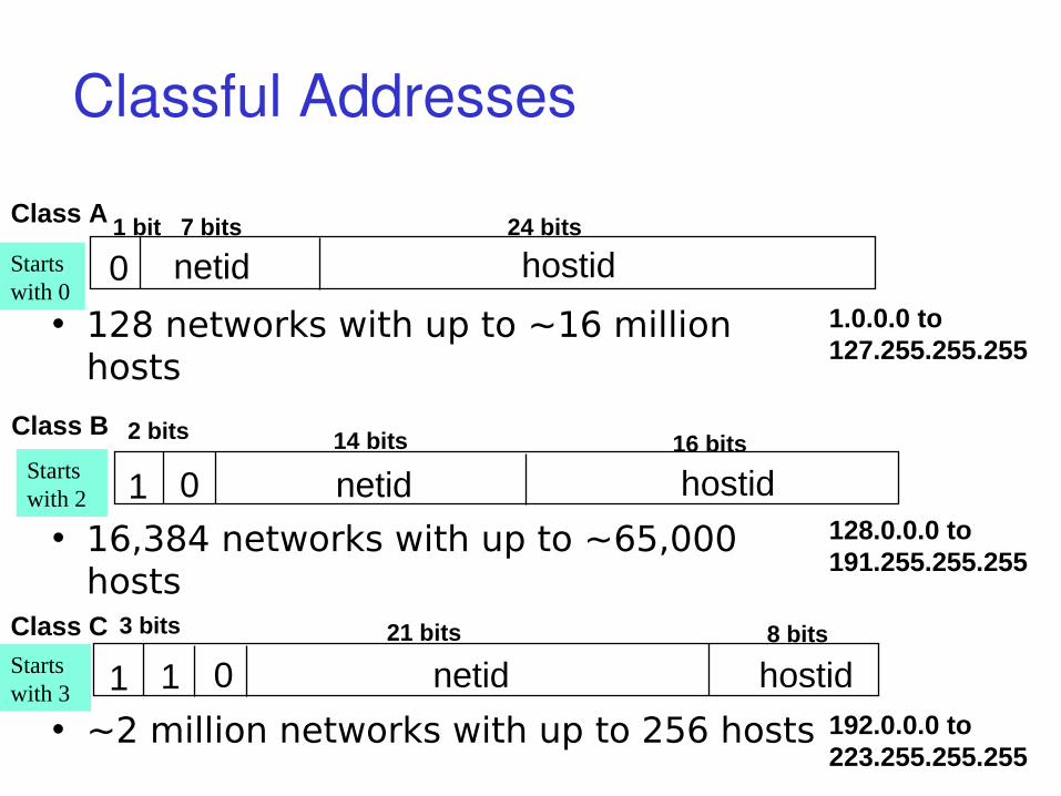
0
1 0
netid
netid
hostid
hostid
1 bit 7 bits 24 bits
14 bits 16 bits
Class A
Class B
• 128 networks with up to ~16 million hosts
• 16,384 networks with up to ~65,000 hosts
1.0.0.0 to127.255.255.255
128.0.0.0 to191.255.255.255
1 1 netid hostid21 bits 8 bitsClass C
0
• ~2 million networks with up to 256 hosts 192.0.0.0 to223.255.255.255
Starts with 0
Starts with 2
Starts with 3
2 bits
3 bits
Classful Address Examples• Upon installing a new Internet connection,
network engineer• Requested a Class A, B, or C network,
depending on expected size of the installed network
• For example• U.S. Department of Defense
• Large network, got a Class A network• University of Maryland,
• Mid-sized network, got a Class B network• Small consulting firm
• Small network, got a Class C network24
Problems with Classful Addressing
• Soon became apparent that classful addressing was inadequate
• For example, a reasonably sized company• Class C, with 254 IP addresses, would be too
small• Next larger choice would be a
• Class B, providing 65,534 IP addresses, too big• Unlikely that thousands of hosts would be
located on a single Ethernet LAN• How could we fix this?
25
Subnetting to the Rescue
• What many network engineers desired was• Ability to take Class B and break its 65,534
addresses into 100-200 smaller networks of 200-300 addresses each
• These smaller networks became known as Subnets, and a standard scheme called subnetting was formalized in RFC 950
• Was in 1985 … around 25 + years ago http://www.faqs.org/rfcs/rfc950.html
26
Subnets and Subnet Masks• Subnetting splits host field
• Subnet + host fields, creates a three-part address
• Network + Subnet + host• Network field remains unchanged,• You start with the Classful classification,
then borrow bits from host to make your subnets
27
Subnets and Subnet Masks
• When subnet created, engineer also creates subnet mask,
• 32 bits long, dotted decimal format, like IP address
• Purpose: Lets routers identify portion IP address that's related to network
• Each bit is either 1 to identify bit positions in the network and subnet fields, or 0 to identify bit positions in host field
• Then, the mask is AND'd with IP Address 255 = What is this value in binary? 11111111 by the way 28
Subnet Mask
Want only the network portion of the address The host part will be zero'd out Routers only care about the network part of the
IP Address Mask then, is composed of all 1's for the
network portion and 0's for the host. See some examples ...
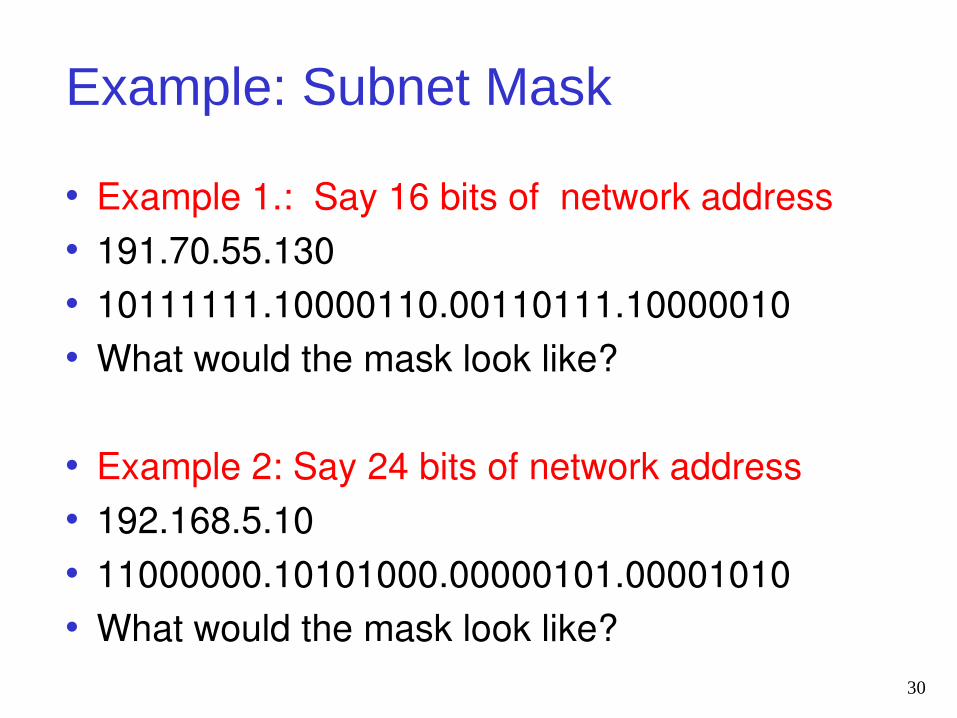
Example: Subnet Mask
• Example 1.: Say 16 bits of network address • 191.70.55.130• 10111111.10000110.00110111.10000010• What would the mask look like?
• Example 2: Say 24 bits of network address• 192.168.5.10• 11000000.10101000.00000101.00001010• What would the mask look like?
30
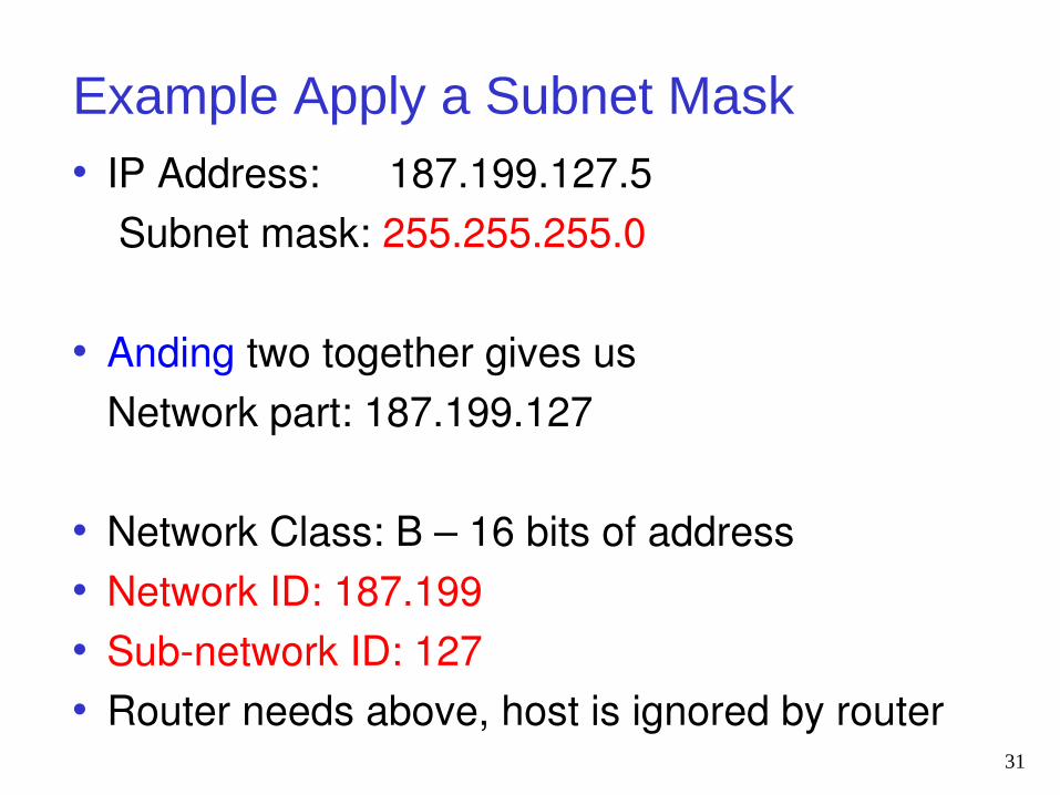
Example Apply a Subnet Mask• IP Address: 187.199.127.5 Subnet mask: 255.255.255.0
• Anding two together gives us Network part: 187.199.127
• Network Class: B – 16 bits of address• Network ID: 187.199• Sub-network ID: 127 • Router needs above, host is ignored by router
31
Subnetting Creates Hierarchy• Idea with subnetting, take one IP address
• Partition it into several IP addresses• Each refers to an actual physical network
• Assume that subnets are geographically close to one another• Because … distant routers only have one IP
address for entire set of subnets• So sending packets to these subnets through one
IP number should route packets in the same general direction
32
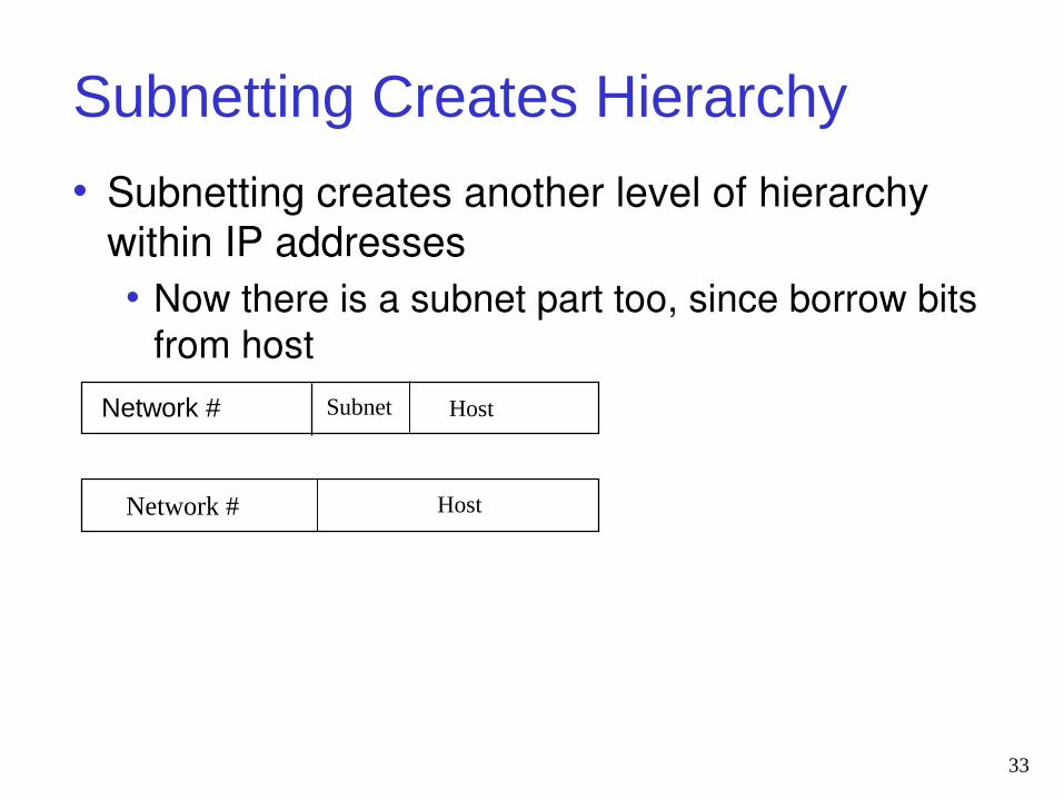
Subnetting Creates Hierarchy
• Subnetting creates another level of hierarchy within IP addresses• Now there is a subnet part too, since borrow bits
from host
33
Network # Subnet Host
HostNetwork #
Addressing Problems not Over
• By 1990, the Internet was facing serious growing pains …• Two most severe problems were
• Explosion of routing table size• Looming exhaustion of Class B networks
• Popularity of Internet triggered flood of new networks, and each network included in routing tables
• Routers were running out of memory, and spending too much time doing address lookup
34
Classless Interdomain Routing (CIDR)• Internet Engineering Task Force (IETF), proposed
• Solution known as classless routing, supernetting, or CIDR
• This addressing scheme currently used• CIDR based on already successful practice of
subnetting• Supernetting allows subnet boundary to move to
the left, into the network part• Groups of neighboring classful networks are
combined into single routing table entries• Size of routing tables reduced through
summarization35
CIDR Example
• Introduced CIDR notation of network192.0.2.0/18
• /18 says that the first 18 bits are network part of address and 14 bits are available for host addresses
• The network part is called the prefix
• Assume that a site requires a network address with 1000 addresses
• How many bits of network address gives us 1000 hosts?– See following slide for table
• With CIDR, network is assigned a continuous block of 1024 addresses with a 22-bit long prefix
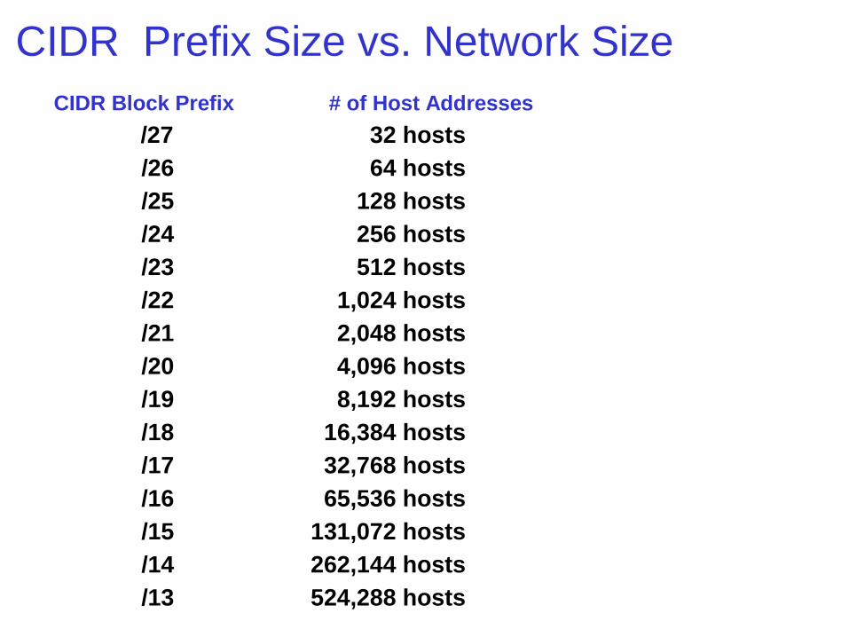
CIDR Prefix Size vs. Network SizeCIDR Block Prefix # of Host Addresses
/27 32 hosts
/26 64 hosts
/25 128 hosts
/24 256 hosts
/23 512 hosts
/22 1,024 hosts
/21 2,048 hosts
/20 4,096 hosts
/19 8,192 hosts
/18 16,384 hosts
/17 32,768 hosts
/16 65,536 hosts
/15 131,072 hosts
/14 262,144 hosts
/13 524,288 hosts
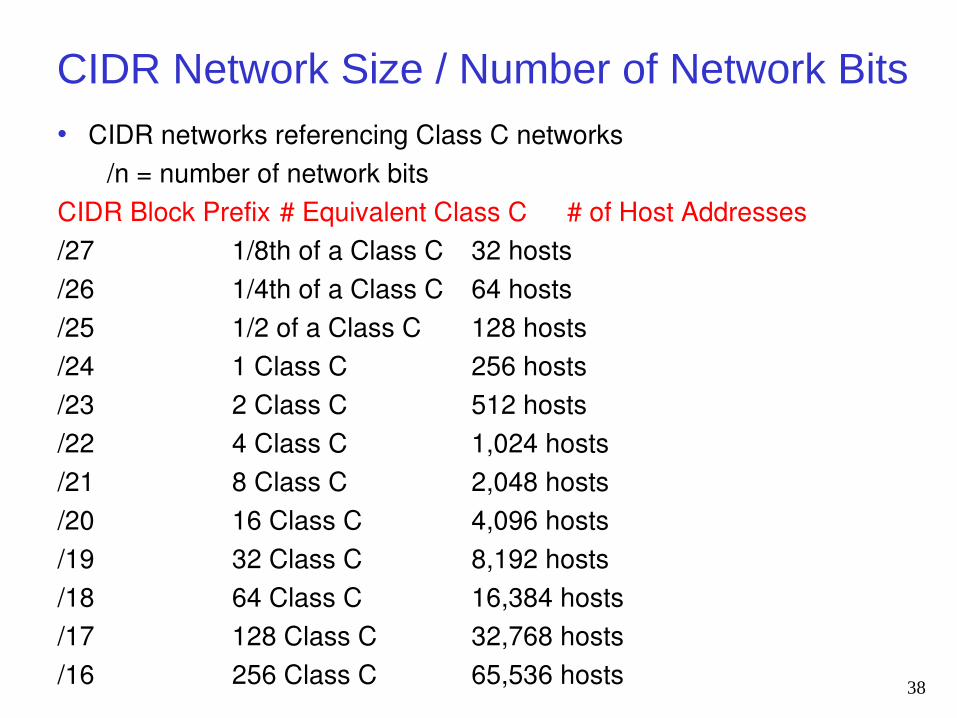
CIDR Network Size / Number of Network Bits• CIDR networks referencing Class C networks
/n = number of network bits CIDR Block Prefix # Equivalent Class C # of Host Addresses/27 1/8th of a Class C 32 hosts/26 1/4th of a Class C 64 hosts/25 1/2 of a Class C 128 hosts/24 1 Class C 256 hosts/23 2 Class C 512 hosts/22 4 Class C 1,024 hosts/21 8 Class C 2,048 hosts/20 16 Class C 4,096 hosts/19 32 Class C 8,192 hosts/18 64 Class C 16,384 hosts/17 128 Class C 32,768 hosts/16 256 Class C 65,536 hosts 38
Ipv4 Address Exhaustion
• Depletion of IPv4 allocation pool a concern since late 1980s when Internet started dramatic growth
• Anticipated shortage driving factor in creating and adopting several technologies1.Classless Inter-Domain Routing (CIDR)
methods in 19932. Network address translation (NAT) and3. Internet Protocol, IPv6, in 1998
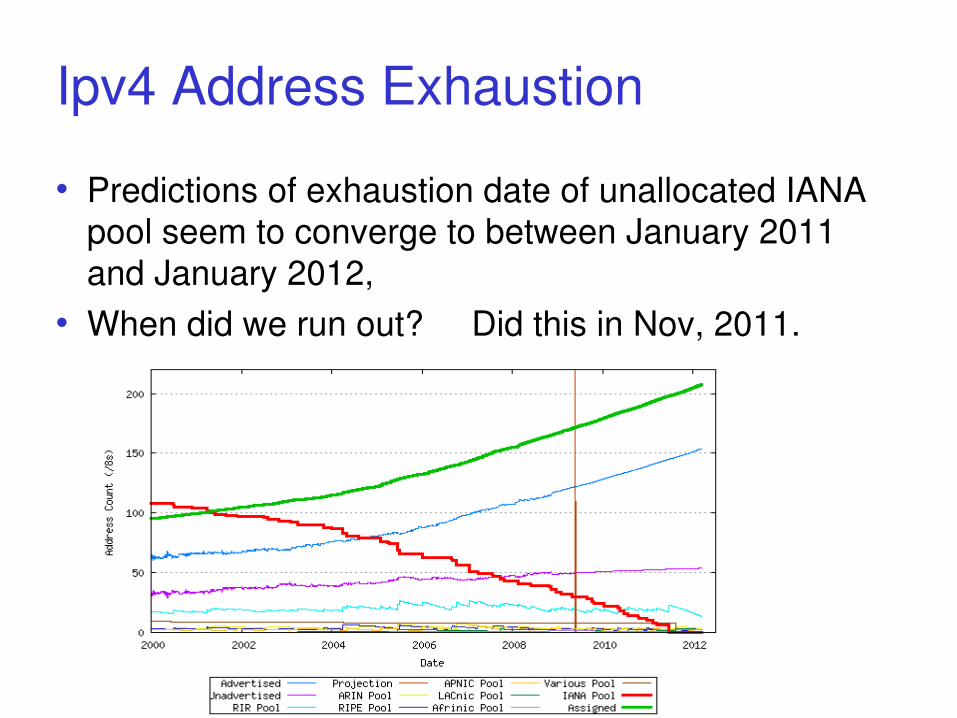
Ipv4 Address Exhaustion
• Predictions of exhaustion date of unallocated IANA pool seem to converge to between January 2011 and January 2012,
• When did we run out? Did this in Nov, 2011.
Ipv4 Address Exhaustion• Predicted that until exhaustion there will be no
significant demand for Ipv6• David Conrad, the general manager of IANA,
acknowledges: "I suspect we are actually beyond a reasonable
time frame where there won't be some disruption. Now it's more a question of how much."
http://en.wikipedia.org/wiki/IPv4_address_exhaustion

Stop here for now
CIDR and Subnetting
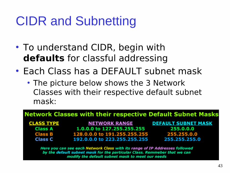
• To understand CIDR, begin with defaults for classful addressing
• Each Class has a DEFAULT subnet mask• The picture below shows the 3 Network
Classes with their respective default subnet mask:
43
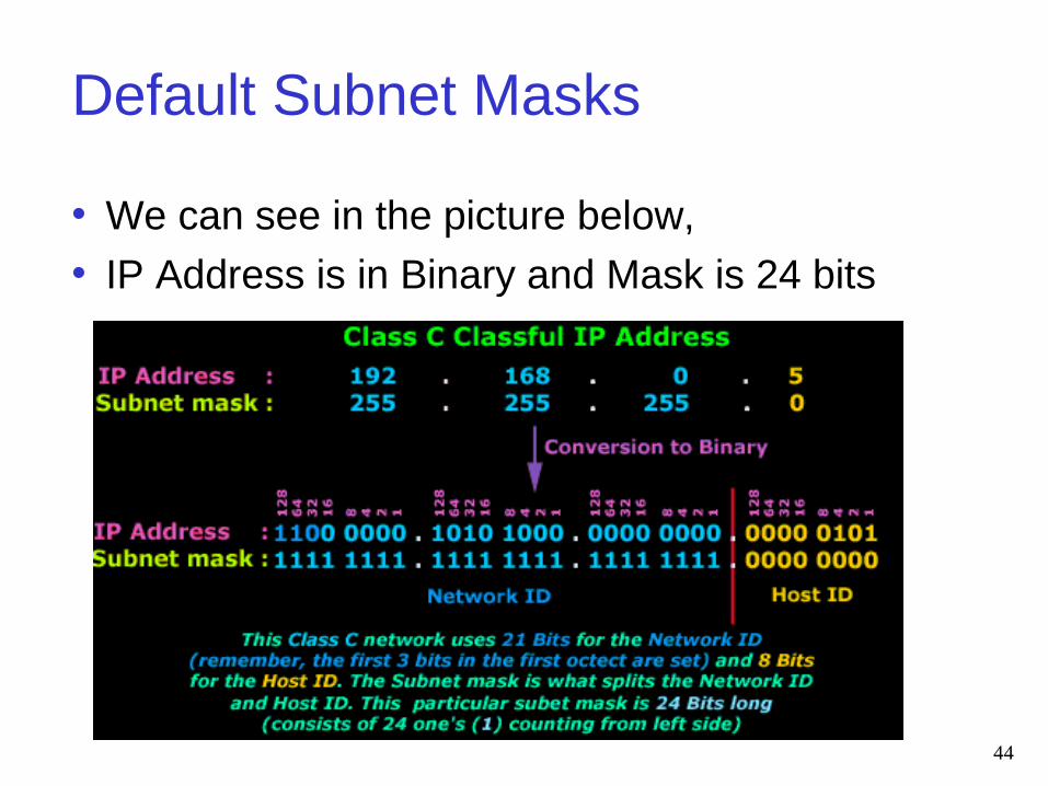
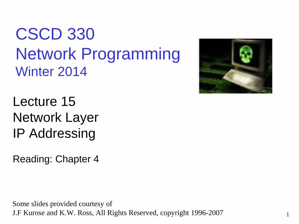
Default Subnet Masks
• We can see in the picture below,• IP Address is in Binary and Mask is 24 bits
44
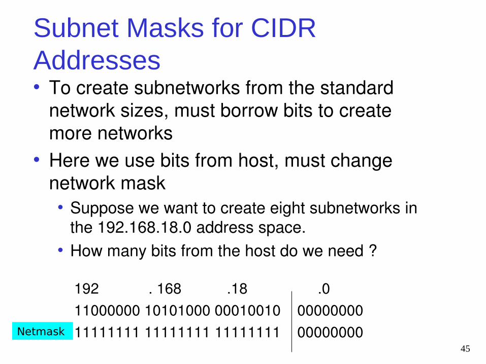
Subnet Masks for CIDR Addresses• To create subnetworks from the standard
network sizes, must borrow bits to create more networks
• Here we use bits from host, must change network mask• Suppose we want to create eight subnetworks in
the 192.168.18.0 address space.• How many bits from the host do we need ?
192 . 168 .18 .0 11000000 10101000 00010010 00000000 11111111 11111111 11111111 00000000
45
Netmask
Subnet Masks for CIDR Addresses
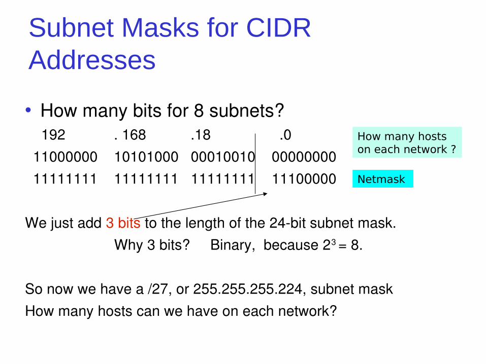
• How many bits for 8 subnets? 192 . 168 .18 .0 11000000 10101000 00010010 00000000 11111111 11111111 11111111 11100000
We just add 3 bits to the length of the 24-bit subnet mask. Why 3 bits? Binary, because 23 = 8.
So now we have a /27, or 255.255.255.224, subnet maskHow many hosts can we have on each network?
Netmask
How many hosts on each network ?
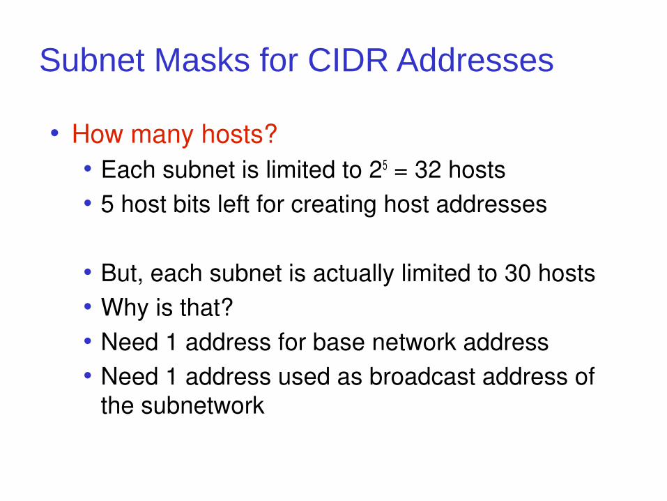
Subnet Masks for CIDR Addresses
• How many hosts?• Each subnet is limited to 25 = 32 hosts• 5 host bits left for creating host addresses
• But, each subnet is actually limited to 30 hosts• Why is that?• Need 1 address for base network address• Need 1 address used as broadcast address of
the subnetwork
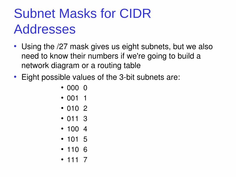
Subnet Masks for CIDR Addresses• Using the /27 mask gives us eight subnets, but we also
need to know their numbers if we're going to build a network diagram or a routing table
• Eight possible values of the 3-bit subnets are:• 000 0• 001 1• 010 2• 011 3• 100 4• 101 5• 110 6• 111 7
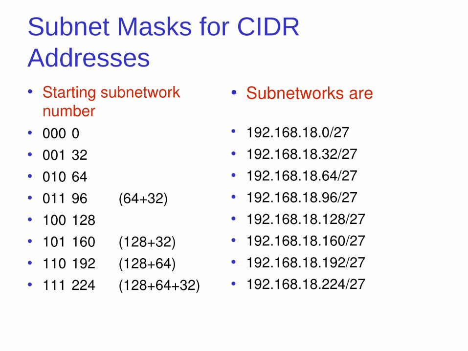
Subnet Masks for CIDR Addresses• Starting subnetwork
number• 000 0• 001 32• 010 64• 011 96 (64+32)• 100 128• 101 160 (128+32)• 110 192 (128+64)• 111 224 (128+64+32)
• Subnetworks are
192.168.18.0/27• 192.168.18.32/27• 192.168.18.64/27• 192.168.18.96/27• 192.168.18.128/27• 192.168.18.160/27• 192.168.18.192/27• 192.168.18.224/27
CIDR and Subnets Created Flexible Network Size • Helped with running out of address space
• Blocks of addresses can be assigned to networks as small as 32 hosts
• Or, over 500,000 hosts• Allows for address assignments that much more
closely fit an organization's specific needs• A single high-level route entry can represent many
lower-level routes in the global routing tables
50
Example of Subnetting
• This will be the lab this week!!!• URLs for Subnet Calculator http://www.subnetonline.com/pages/ subnet-calculators/ip-subnet-calculator.php
http://www.techzoom.net/tools/network-subnet-calculator.en
52
Router Table Aggregation
CIDR Also Helped with Route Aggregation
• Currently, big blocks of addresses assigned to large Internet Service Providers (ISPs)
• Re-allocate portions of their address blocks to their customers• Assigns its customers CIDR addresses from that block
• Customers, smaller ISPs, and in turn re-allocate portions of their address block to their users
• Yet global routing tables for all these networks can be represented by single route entry
53
CIDR Also Helped with Route Aggregation or Supernetting
• CIDR provides routing prefix aggregation, also known as supernetting• Example: Sixteen Contiguous /24 Networks
• Aggregated and advertised as a single /20 route• If first 20 bits of their network addresses match!!
• Two aligned contiguous /20s may then be aggregated to a /19, and so forth
• Allows a significant reduction in the number of routes that have to be advertised
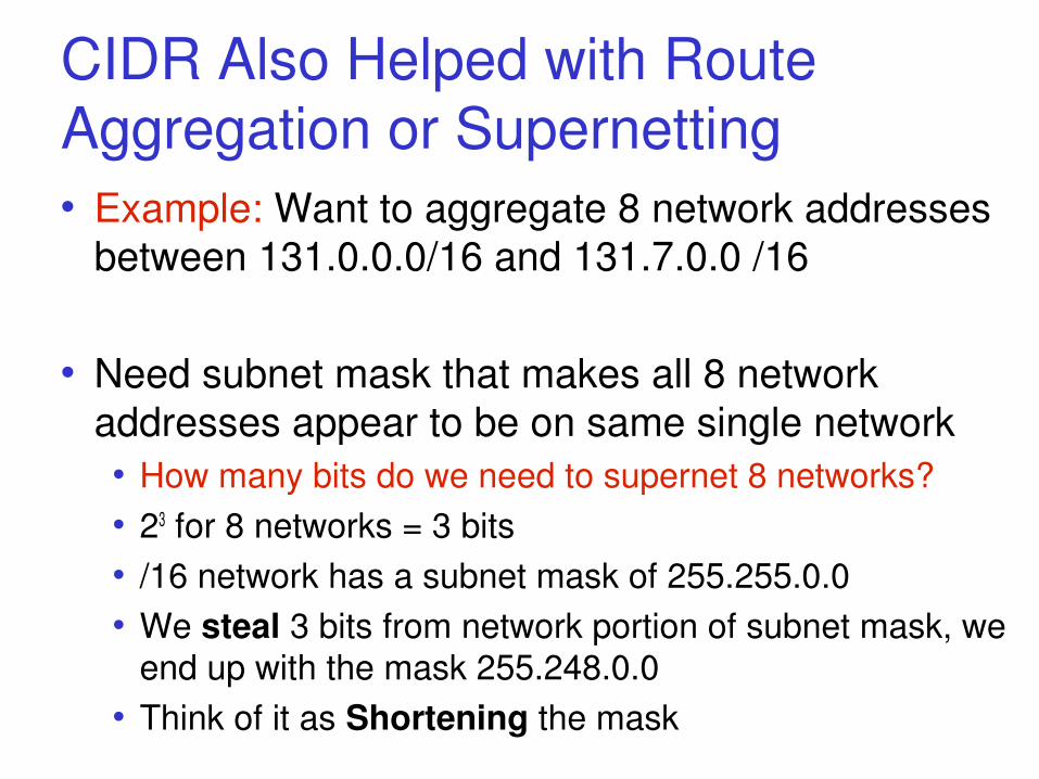
CIDR Also Helped with Route Aggregation or Supernetting• Example: Want to aggregate 8 network addresses
between 131.0.0.0/16 and 131.7.0.0 /16
• Need subnet mask that makes all 8 network addresses appear to be on same single network• How many bits do we need to supernet 8 networks? • 23 for 8 networks = 3 bits• /16 network has a subnet mask of 255.255.0.0• We steal 3 bits from network portion of subnet mask, we
end up with the mask 255.248.0.0• Think of it as Shortening the mask
Supernetting
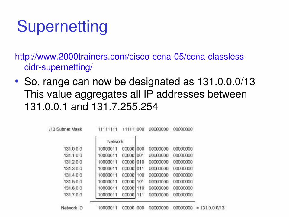
http://www.2000trainers.com/cisco-ccna-05/ccna-classless-cidr-supernetting/
• So, range can now be designated as 131.0.0.0/13 This value aggregates all IP addresses between 131.0.0.1 and 131.7.255.254
Reserved AddressesTwo Reserved Addresses
127.0.0.1 – What is this called?0.0.0.0 – Also reserved
Can we route to these normally?Blocks of Private Addresses
10.0.0.0/8 (10.0.0.0 to 10.255.255.255)172.16.0.0/12 (172.16.0.0 to 172.31.255.255)192.168.0.0/16 (192.168.0.0 to 192.168.255.255)169.254.0.0/16 (169.254.0.0 to 169.254.255.255)
Small companies use: 172.16.0.0Home users use: 192.168.0.0
References• Packet Fragmentation
http://www.cisco.com/en/US/tech/tk827/tk369/technologies_white_paper09186a00800d6979.shtml
• Subnettinghttp://microcomputer-network.net/calculate-subnet-mask
• More Subnettinghttp://learn-networking.com/network-design/how-to-subnet-a-
network• Subnetting Made Easy
http://www.techexams.net/forums/ccna-ccent/38772-subnetting-made-easy.html
• Calculatorshttp://jodies.de/ipcalchttp://www.aboutmyip.com/AboutMyXApp/SubnetCalculator.jsp
59
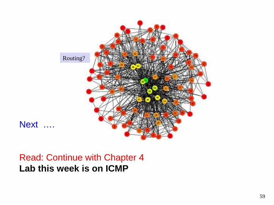
Next ….
Read: Continue with Chapter 4Lab this week is on ICMP
Routing?
1


16
Network Addressing


23


29
Subnet Mask
Want only the network portion of the address The host part will be zero'd out Routers only care about the network part of the
IP Address Mask then, is composed of all 1's for the
network portion and 0's for the host. See some examples ...


57
Reserved AddressesTwo Reserved Addresses
127.0.0.1 – What is this called?0.0.0.0 – Also reserved
Can we route to these normally?Blocks of Private Addresses
10.0.0.0/8 (10.0.0.0 to 10.255.255.255)172.16.0.0/12 (172.16.0.0 to 172.31.255.255)192.168.0.0/16 (192.168.0.0 to 192.168.255.255)169.254.0.0/16 (169.254.0.0 to 169.254.255.255)
Small companies use: 172.16.0.0Home users use: 192.168.0.0