Embed Size (px)
Citation preview
500 SeriesAdjustable Popoff & InlineRelief Valves.5 to 150 PSIG
Technical Data
• Popoff or Inline Valves
• Adjustable Crack Pressure
• Zero Leakage
• Optional Factory Preset
• Accurate Set Pressure
• Wide Range of CrackingPressure
• Tamper Proof Adjustment
• 100% Seat Leakage Tested
• Systems Overpressure Protection
• Storage Tanks
• Freon Recovery Systems
• Medical Equipment
• Refrigeration & Heating Equipment
• Measuring & Dispensing Pumps
• Communications Equipment
• Process Control Instruments
• R & D Pilot Plants
Body Construction Materials:
O-ring Materials:
Spring Materials:
Operating Pressure:
Inline Valve Proof Pressure:
Inline Valve Burst Pressure:
Temperature Range:
Connection Sizes:
• Aluminum, Brass, 303 or 316 Stainless Steel
• Buna N, Ethylene Propylene, Neoprene,Silicone, Teflon® or Viton®
• 302 Stainless Steel or 17-7PH Stainless Steel
• Vacuum to 200 PSIG (14 BAR)
• 400 PSIG (28 BAR)
• Above 500 PSIG (34 BAR)
• -320° F to +400° F (-196° C to +204° C)Based on o-ring material, see “How to Order”
• 1/8 inch to 1-1/4 inch
How it Works
CLOSEDResilient seal designprevents leakage.Sealing efficiencyincreases withincreased pressure upto cracking pressure.Metal-to-metal poppetstop supports springload, preventssticking.
OPENWhen systempressure overcomesspring force, poppetopens. As pressurecontinues to rise,variable orificebetween poppet andbody increases,allowing greater flow.
RESEALINGResilient seal automatically establishesline of contact with spherical seat. Sealprovides zero leakage at reseal.
NOTE: Proper filtration is recommended to prevent damage to sealing surfaces.
Features Applications
Fred C. Gilbert Co. 106 Norris Road
Bakersfield, Ca. 93308 661-399-9569
fax 661-393-9654
2
500 Series.5–150 PSI
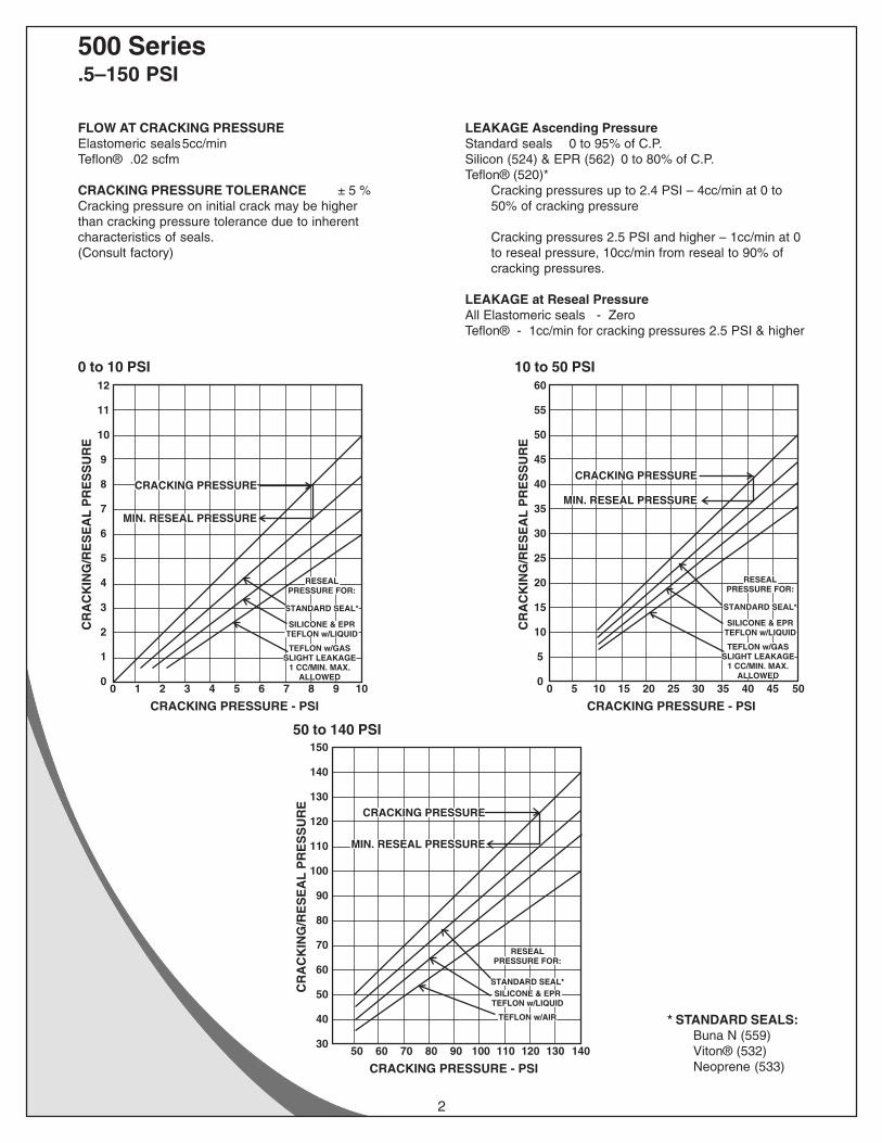
FLOW AT CRACKING PRESSUREElastomeric seals5cc/minTeflon® .02 scfm
CRACKING PRESSURE TOLERANCE ± 5 %Cracking pressure on initial crack may be higherthan cracking pressure tolerance due to inherentcharacteristics of seals.(Consult factory)
LEAKAGE Ascending PressureStandard seals 0 to 95% of C.P.Silicon (524) & EPR (562) 0 to 80% of C.P.Teflon® (520)*
Cracking pressures up to 2.4 PSI – 4cc/min at 0 to50% of cracking pressure
Cracking pressures 2.5 PSI and higher – 1cc/min at 0to reseal pressure, 10cc/min from reseal to 90% ofcracking pressures.
LEAKAGE at Reseal PressureAll Elastomeric seals - ZeroTeflon® - 1cc/min for cracking pressures 2.5 PSI & higher
TEFLON w/AIR
STANDARD SEAL*
CRACKING PRESSURE - PSI
CR
AC
KIN
G/R
ES
EA
L P
RE
SS
UR
E
50 60 70 80 90 100 110 120 130 14030
40
50
60
70
80
90
100
110
120
130
140
150
RESEALPRESSURE FOR:
CRACKING PRESSURE
MIN. RESEAL PRESSURE
SILICONE & EPRTEFLON w/LIQUID
CRACKING PRESSURE - PSI
CR
AC
KIN
G/R
ES
EA
L P
RE
SS
UR
E
0 5 10 15 20 25 30 35 40 45 500
5
10
15
20
25
30
35
40
45
50
55
60
TEFLON w/GASSLIGHT LEAKAGE
1 CC/MIN. MAX.ALLOWED
SILICONE & EPRTEFLON w/LIQUID
STANDARD SEAL*
RESEALPRESSURE FOR:
CRACKING PRESSURE
MIN. RESEAL PRESSURE
TEFLON w/GASSLIGHT LEAKAGE
1 CC/MIN. MAX.ALLOWED
SILICONE & EPRTEFLON w/LIQUID
STANDARD SEAL*
RESEALPRESSURE FOR:
CRACKING PRESSURE
MIN. RESEAL PRESSURE
CRACKING PRESSURE - PSI
CR
AC
KIN
G/R
ES
EA
L P
RE
SS
UR
E
0 1 2 3 4 5 6 7 8 9 100
1
2
3
4
5
6
7
8
9
10
11
12
* STANDARD SEALS:Buna N (559)Viton® (532)Neoprene (533)
0 to 10 PSI 10 to 50 PSI
50 to 140 PSI

3
500 Series.5–150 PSI
Hydraulic Flow Curves (500-M) Popoff Relief Valves
Hydraulic Fluid MIL-H-5606 Rate of Flow - GPM
PS
I
4
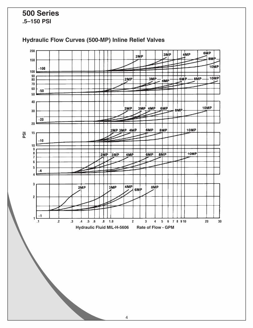
500 Series.5–150 PSI
Hydraulic Flow Curves (500-MP) Inline Relief Valves
Hydraulic Fluid MIL-H-5606 Rate of Flow - GPM
PS
I
5
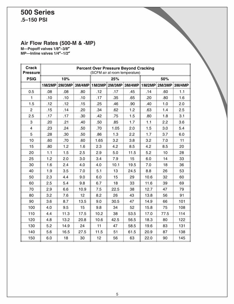
500 Series.5–150 PSI
Air Flow Rates (500-M & -MP)M—Popoff valves 1/8″″″″″–3/8″″″″″MP—Inline valves 1/4″″″″″–1/2″″″″″
CrackPressure
Percent Over Pressure Beyond Cracking(SCFM air at room temperature)
PSIG 10% 25% 50%
1M/2MP 2M/3MP 3M/4MP 1M/2MP 2M/3MP 3M/4MP 1M/2MP 2M/3MP 3M/4MP
0.5 .08 .08 .80 .12 .17 .45 .14 .60 1.1
1 .10 .10 .10 .17 .35 .65 .20 .80 1.6
1.5 .12 .12 .15 .25 .46 .90 .40 1.0 2.0
2 .15 .14 .20 .34 .62 1.2 .63 1.4 2.5
2.5 .17 .17 .30 .42 .75 1.5 .80 1.8 3.1
3 .20 .21 .40 .50 .85 1.7 1.1 2.2 3.6
4 .23 .24 .50 .70 1.05 2.0 1.5 3.0 5.4
5 .28 .30 .50 .86 1.3 2.2 1.7 3.7 6.0
10 .60 .70 .60 1.65 3.2 3.8 3.2 7.0 11
15 .80 1.2 1.6 2.3 4.2 8.5 4.2 8.5 20
20 1.1 1.5 2.5 2.9 5.0 11.5 5.2 10 28
25 1.2 2.0 3.0 3.4 7.9 15 6.0 14 33
30 1.6 2.4 4.0 4.0 10.1 19.5 7.0 18 36
40 1.9 3.5 7.0 5.1 13 24.5 8.8 26 53
50 2.3 4.4 9.0 6.0 15 29 10.6 32 60
60 2.5 5.4 9.8 6.7 18 33 11.6 39 69
70 2.9 6.6 10.9 7.5 22.5 38 12.7 47 79
80 3.2 7.6 12 8.2 26 43 13.8 56 91
90 3.6 8.7 13.5 9.0 30.5 47 14.9 66 101
100 4.0 9.5 15 9.8 34 52 15.8 75 108
110 4.4 11.3 17.5 10.2 38 53.5 17.0 77.5 114
120 4.8 13.2 20.8 10.6 42.5 56.5 18.3 80 122
130 5.2 14.9 24 11 47 58.5 19.6 83 131
140 5.6 16.5 27.5 11.5 51 61.5 20.9 87 138
150 6.0 18 30 12 56 63 22.0 90 145
6
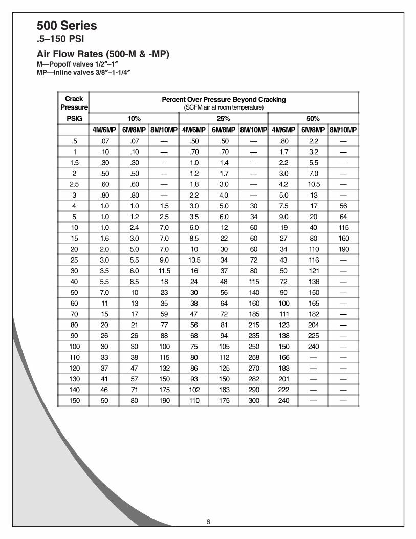
500 Series.5–150 PSI
Air Flow Rates (500-M & -MP)M—Popoff valves 1/2″″″″″–1″″″″″MP—Inline valves 3/8″″″″″–1-1/4″″″″″
CrackPressure
Percent Over Pressure Beyond Cracking(SCFM air at room temperature)
PSIG 10% 25% 50%
4M/6MP 6M/8MP 8M/10MP 4M/6MP 6M/8MP 8M/10MP 4M/6MP 6M/8MP 8M/10MP
.5 .07 .07 — .50 .50 — .80 2.2 —
1 .10 .10 — .70 .70 — 1.7 3.2 —
1.5 .30 .30 — 1.0 1.4 — 2.2 5.5 —
2 .50 .50 — 1.2 1.7 — 3.0 7.0 —
2.5 .60 .60 — 1.8 3.0 — 4.2 10.5 —
3 .80 .80 — 2.2 4.0 — 5.0 13 —
4 1.0 1.0 1.5 3.0 5.0 30 7.5 17 56
5 1.0 1.2 2.5 3.5 6.0 34 9.0 20 64
10 1.0 2.4 7.0 6.0 12 60 19 40 115
15 1.6 3.0 7.0 8.5 22 60 27 80 160
20 2.0 5.0 7.0 10 30 60 34 110 190
25 3.0 5.5 9.0 13.5 34 72 43 116 —
30 3.5 6.0 11.5 16 37 80 50 121 —
40 5.5 8.5 18 24 48 115 72 136 —
50 7.0 10 23 30 56 140 90 150 —
60 11 13 35 38 64 160 100 165 —
70 15 17 59 47 72 185 111 182 —
80 20 21 77 56 81 215 123 204 —
90 26 26 88 68 94 235 138 225 —
100 30 30 100 75 105 250 150 240 —
110 33 38 115 80 112 258 166 — —
120 37 47 132 86 125 270 183 — —
130 41 57 150 93 150 282 201 — —
140 46 71 175 102 163 290 222 — —
150 50 80 190 110 175 300 240 — —

7
500 Series.5–150 PSI
Air Flow Rates (D500-M)Popoff valves with deflector cap 1/8″″″″″–3/8″″″″″
CrackPressure
Percent Over Pressure Beyond Cracking(SCFM air at room temperature)
PSIG 10% 25% 50%
1M 2M 3M 1M 2M 3M 1M 2M 3M
.5 .12 .20 .15 .24 .50 .50 .44 1.2 1.1
1 .21 .30 .30 .40 .85 .85 .73 2.0 1.9
1.5 .21 .30 .30 .42 1.0 1.0 .80 2.7 3.1
2 .21 .30 .30 .45 1.2 1.2 .95 3.5 5.0
2.5 .22 .30 .30 .49 1.3 1.3 1.1 4.3 6.2
3 .23 .30 .30 .52 1.6 1.6 1.25 5.4 8.0
4 .23 .30 .30 .58 2.1 2.1 1.5 7.5 12
5 .32 .30 .30 .60 2.2 4.5 1.7 8.3 14
10 .70 .34 .40 1.6 2.5 14 3.2 12.6 23
15 1.4 1.3 1.5 2.0 6.0 18 3.9 16.5 29
20 1.8 2.2 3.0 2.7 10 23 5.4 21 36
25 1.9 3.0 8.0 2.8 11.5 27 6.0 23 40
30 2.0 4.0 14 3.0 14 32 7.0 27 47
40 2.3 5.9 26 3.5 18 42 9.0 33 59
50 2.4 8.0 39 3.8 25 54 10.5 40 74
60 3.2 17 43 4.6 33 62 11.4 46 —
70 4.0 26 47 5.5 41 70 12.4 52 —
80 4.9 36 52 6.4 50 79 13.7 59 —
90 5.9 46 58 7.5 61 89 15 67 —
100 7.0 56 65 8.5 72 100 16 76 —
110 7.3 56 65 9.5 73 113 24 80 —
120 7.7 57 66 12.8 74 127 33 84 —
130 8.1 58 67 16.2 76 142 43 89 —
140 8.6 59 68 20 78 158 53 96 —
150 9.0 61 70 25 80 176 60 104 —
8
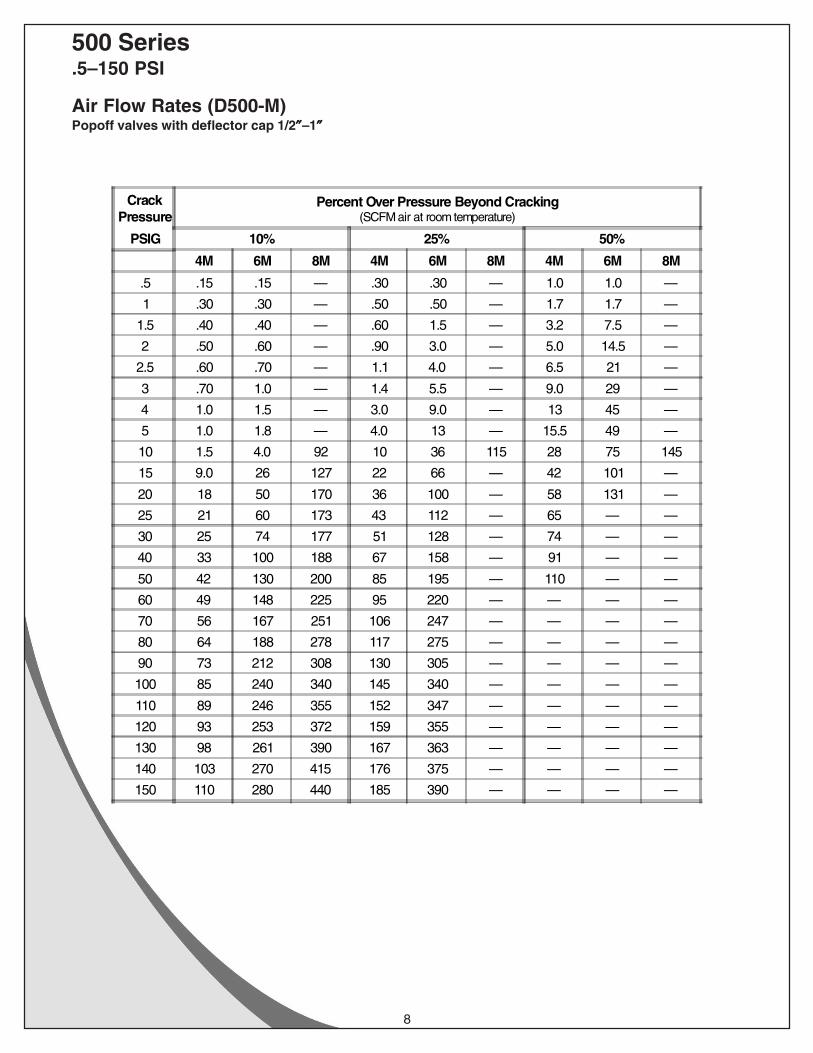
500 Series.5–150 PSI
Air Flow Rates (D500-M)Popoff valves with deflector cap 1/2″″″″″–1″″″″″
CrackPressure
Percent Over Pressure Beyond Cracking(SCFM air at room temperature)
PSIG 10% 25% 50%
4M 6M 8M 4M 6M 8M 4M 6M 8M
.5 .15 .15 — .30 .30 — 1.0 1.0 —
1 .30 .30 — .50 .50 — 1.7 1.7 —
1.5 .40 .40 — .60 1.5 — 3.2 7.5 —
2 .50 .60 — .90 3.0 — 5.0 14.5 —
2.5 .60 .70 — 1.1 4.0 — 6.5 21 —
3 .70 1.0 — 1.4 5.5 — 9.0 29 —
4 1.0 1.5 — 3.0 9.0 — 13 45 —
5 1.0 1.8 — 4.0 13 — 15.5 49 —
10 1.5 4.0 92 10 36 115 28 75 145
15 9.0 26 127 22 66 — 42 101 —
20 18 50 170 36 100 — 58 131 —
25 21 60 173 43 112 — 65 — —
30 25 74 177 51 128 — 74 — —
40 33 100 188 67 158 — 91 — —
50 42 130 200 85 195 — 110 — —
60 49 148 225 95 220 — — — —
70 56 167 251 106 247 — — — —
80 64 188 278 117 275 — — — —
90 73 212 308 130 305 — — — —
100 85 240 340 145 340 — — — —
110 89 246 355 152 347 — — — —
120 93 253 372 159 355 — — — —
130 98 261 390 167 363 — — — —
140 103 270 415 176 375 — — — —
150 110 280 440 185 390 — — — —

9
500 Series.5–150 PSI
Dimensions (Inches)
Popoff Valve Dimensions
Pipe SizeMale
L L1 Hex D diaMax
1/8" 1.14 .98 ½ 0.63
1/4" 1.38 1.20 5/8 0.90
3/8" 1.43 1.25 3/4 1.21
1/2" 1.98 1.74 1 1.45
3/4" 2.31 2.07 1-1/8 1.45
1" 3.16 2.85 1-1/2 1.89
Valve Size & Codes
Size
PipeThread
MalePipe ThreadMale/Female
British PipeThread
Male/Female
BritishTaper Pipe
Male
1/8" 1M 1S
1/4" 2M 2MP 2SX 2S
3/8" 3M 3MP 3SX 3S
1/2" 4M 4MP 4SX 4S
3/4" 6M 6MP 6SX 6S
1" 8M 8MP 8S
1-1/4" 10MP
Inline Valve Dimensions
Pipe Size Male& Female
L Hex
1/4" 1.62 3/4
3/8" 2.08 7/8
1/2" 2.34 1-1/8
3/4" 2.72 1-1/4
1" 3.62 1-1/2
1-1/4" 4.67 1-7/8
D Dia
LL1
HexAcrossFlats
D Dia
LL1
HexAcrossFlats
HexAcross
Flats L
Popoff
Inline
10
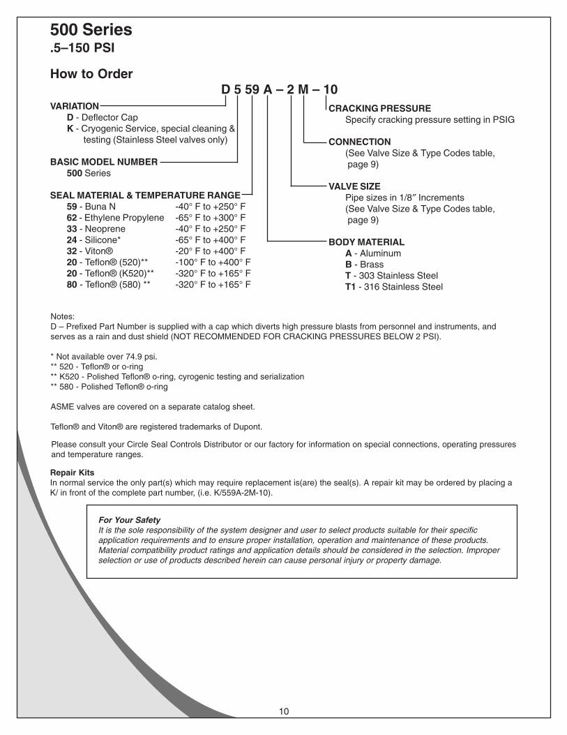
500 Series.5–150 PSI
How to OrderD 5 59 A – 2 M – 10
VARIATIOND - Deflector CapK - Cryogenic Service, special cleaning &
testing (Stainless Steel valves only)
BASIC MODEL NUMBER500 Series
SEAL MATERIAL & TEMPERATURE RANGE59 - Buna N -40° F to +250° F62 - Ethylene Propylene -65° F to +300° F33 - Neoprene -40° F to +250° F24 - Silicone* -65° F to +400° F32 - Viton® -20° F to +400° F20 - Teflon® (520)** -100° F to +400° F20 - Teflon® (K520)** -320° F to +165° F80 - Teflon® (580) ** -320° F to +165° F
CRACKING PRESSURESpecify cracking pressure setting in PSIG
CONNECTION(See Valve Size & Type Codes table, page 9)
VALVE SIZEPipe sizes in 1/8″ Increments(See Valve Size & Type Codes table, page 9)
BODY MATERIALA - AluminumB - BrassT - 303 Stainless SteelT1 - 316 Stainless Steel
Notes:D – Prefixed Part Number is supplied with a cap which diverts high pressure blasts from personnel and instruments, andserves as a rain and dust shield (NOT RECOMMENDED FOR CRACKING PRESSURES BELOW 2 PSI).
* Not available over 74.9 psi.** 520 - Teflon® or o-ring** K520 - Polished Teflon® o-ring, cyrogenic testing and serialization** 580 - Polished Teflon® o-ring
ASME valves are covered on a separate catalog sheet.
Teflon® and Viton® are registered trademarks of Dupont.
Please consult your Circle Seal Controls Distributor or our factory for information on special connections, operating pressuresand temperature ranges.
Repair KitsIn normal service the only part(s) which may require replacement is(are) the seal(s). A repair kit may be ordered by placing aK/ in front of the complete part number, (i.e. K/559A-2M-10).
For Your SafetyIt is the sole responsibility of the system designer and user to select products suitable for their specificapplication requirements and to ensure proper installation, operation and maintenance of these products.Material compatibility product ratings and application details should be considered in the selection. Improperselection or use of products described herein can cause personal injury or property damage.