Embed Size (px)
Citation preview
Tra
ansfo
orme
er ProPro
Cotectoduc
CSC-3tion Ict Gu
326 IED
uide

Note
the in
corre
: The comp
nstruction a
esponding se
Wecomdiss
Thisask
Thedeeconas apro
ManBeij
TelFaxEmWe
Add
any keeps t
at anywhere
ervice.
e reserve all rigmmercial propsemination to
s document h
ked to notify us
e data containemed to be anstantly seek ta result; it is pduct and this
nufacturer: jing Sifang Au
: +86 10 6296x: +86 10 8278ail: sf_sales@
ebsite: http://ww
d: No.9, Shang
C
the right to p
e, please co
® is regist
ghts to this doprietary right third parties, i
has been cares as soon as p
ned in this mastatement of
o ensure that possible that tinformation pr
utomation Co.,
62554, +86 10 83625
@sf-auto.comww.sf-auto.co
gdi 4th Street,
Copyright ow
perfect the i
ontact our c
tered tradema
ocument, evenis registered
is not permitte
efully checkedpossible.
anual is intendf guaranteed our products athere may be roduct.
, Ltd.
62961515 ex
om
, Haidian Distr
wner: Beijin
instruction. I
company in
rk of Beijing S
n in the event td. Improper ued.
. If the user n
ded solely for properties. Inare developedsome differen
xt. 8998
rict, Beijing, P
Doc. Co
Iss
ng Sifang A
If equipmen
time. We w
Sifang Automa
that a patent iuse, in partic
evertheless d
the IED descn the interestsd to the latest tnces between
.R.C.100085
Version
ode: 0SF.49
sued Date:
Automation
nts do not ag
will provide
ation Co., Ltd.
is issued and cular reprodu
detects any er
cription and iss of our custotechnological
n the hardware
n:V1.11
92.054(E)
2013.12
Co., Ltd
gree with
you with
a different uction and
rors, he is
s not to be omers, we standards e/software

CSC
spee
for tr
powe
appli
F
th
-t
S
p
U
u
F
-m
U
in
W
o
.
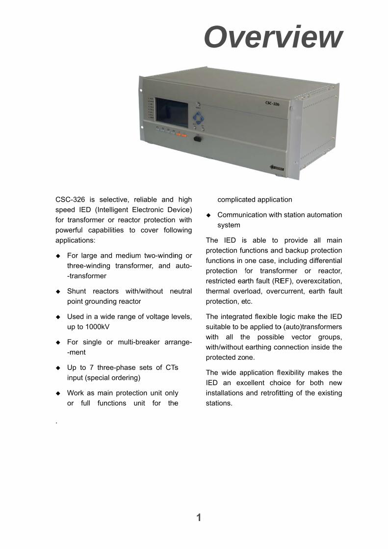
C-326 is se
ed IED (Int
ransformer
erful capab
ications:
For large an
hree-windin
transformer
Shunt reac
point ground
Used in a w
up to 1000kV
For single
ment
Up to 7 thr
nput (specia
Work as ma
or full fun
elective, re
telligent Ele
or reactor
bilities to
nd medium
ng transform
r
ctors with/
ding reactor
wide range o
V
or multi-br
ree-phase s
al ordering)
ain protectio
nctions un
liable and
ectronic De
protection
cover follo
m two-windin
mer, and
without ne
r
of voltage le
reaker arra
sets of CTs
on unit only
nit for the
O
1
high
evice)
with
owing
ng or
auto-
eutral
evels,
ange-
Ts
y
e
T
pr
fu
pr
re
th
pr
T
su
w
w
pr
T
IE
in
st
Ov
complica
Commun
system
he IED is
rotection fu
unctions in o
rotection f
estricted ea
hermal over
rotection, et
he integrate
uitable to be
with all th
with/without
rotected zo
he wide ap
ED an exc
nstallations
tations.
verv
ted applicat
nication with
s able to
nctions and
one case, in
for transfo
rth fault (RE
rload, overc
tc.
ed flexible l
e applied to
he possible
earthing co
ne.
pplication fl
cellent cho
and retrofit
vie
tion
h station aut
provide a
d backup pr
ncluding dif
ormer or
EF), overex
rcurrent, ea
logic make
o (auto)trans
e vector
onnection in
exibility ma
oice for bo
tting of the
ew
tomation
all main
rotection
fferential
reactor,
xcitation,
arth fault
the IED
sformers
groups,
nside the
akes the
oth new
existing
Feature
2
Protection and monitoring IED with
extensive functional library, user
configuration possibility and expand-
-able hardware design to meet with
user’s special requirements
Inter-lock between two CPU modules,
avoiding mal-operation due to internal
severe fault of one module
Transformer differential protection
(87T)
Treble slope percent differential
protection
Automatic CT ratio matching
Automatic vector group and zero
sequence current compensation
Settable 2nd harmonic restraint
function for transformer inrush
Fuzzy waveform recognition
restraint function for transformer
inrush
3rd or 5th harmonic restraint for
overexcitation
CT saturation detection
CT secondary circuit supervison
Differential current alarm
Reactor differential protection (87R)
Treble slope percent differential
protection
Automatic CT ratio matching
CT saturation detection
CT secondarycircuit supervison
Differential current supervision
Restricted earth fault protection for
transformer (87NT)
Two slope percent REF protection
Automatic CT ratio matching
CT saturation recognition
REF differential current super-
-vision
Restricted earth fault protection for
reactor(87NR)
Two slope percent REF protection
Automatic CT ratio matching
CT saturation recognition
REF differential current
supervision
Interturn fault protection (16)
Based on zero sequence direction
Self-adpative interturn fault
detection
A complete protection functions library,
include:
Transformer differential protection
(87T)
Reactor differential protection
(87R)
Restricted earth fault protection
for transformer(87NT)
Restricted earth fault protection
for reactor(87NR)
Inter-turn protection (16)
Overcurrent protection (50, 51,
67)
Earth fault protection (50N, 51N,
67N)
Neutral earth fault protection (50G,
51G, 67G)
Feature
3
Thermal overload protection (49)
Overload protection (50OL)
Delta winding overload protection
(50OL)
Overexcitation protection (24)
Overvoltage protection (59)
Circuit breaker failure protection
(50BF)
Poles discordance protection
(50PD)
Dead zone protection (50DZ)
Voltage transformer secondary
circuit supervision (97FF)
Current transformer secondary
circuit supervision
2 sets external trip commands (BIs →
BOs
Self-supervision to all modules in the
IED
Complete information recording:
tripping reports, alarm reports, startup
reports and general operation reports.
Any kinds of reports can be stored up
to 2000 and be memorized in case of
power disconnection
Up to three electric /optical Ethernet
ports can be selected to communicate
with substation automation system by
IEC61850 or IEC60870-5-103
protocols
Up to two electric RS-485 ports can be
selected to communicate with
substation automation system by
IEC60870-5-103 protocol
Time synchronization via network
(SNTP), pulse and IRIG-B mode
Configurable LEDs and output relays
satisfied users’ requirement
Versatile human-machine interface
Multifunctional software tool for setting,
monitoring, fault recording analysis,
configuration, etc.
Function
4
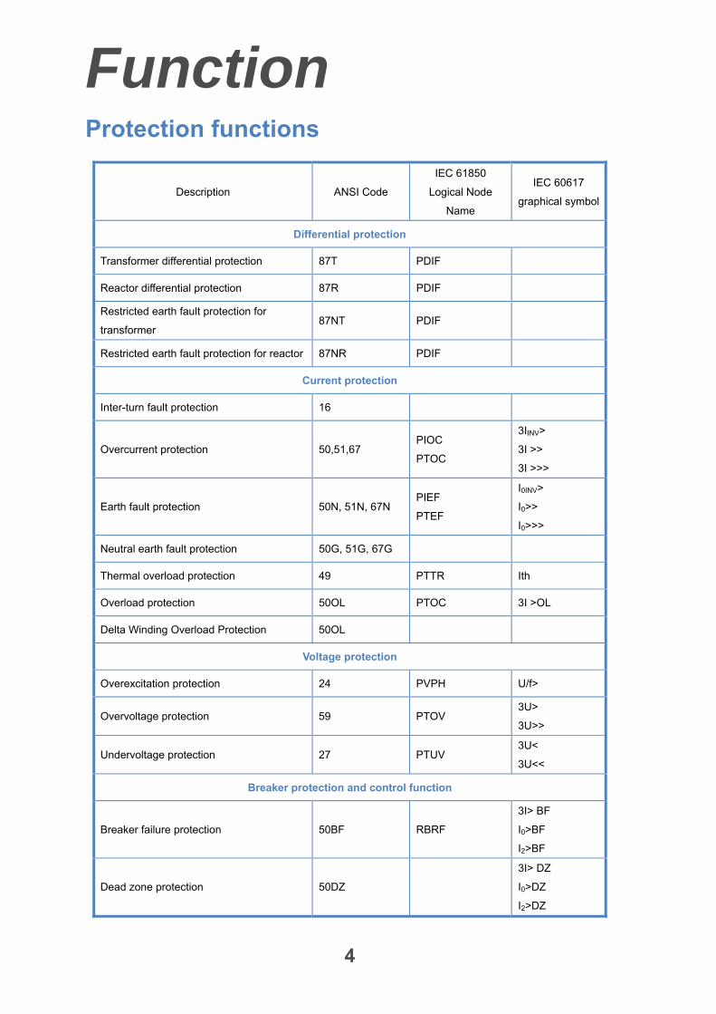
Protection functions
Description ANSI Code
IEC 61850
Logical Node
Name
IEC 60617
graphical symbol
Differential protection
Transformer differential protection 87T PDIF
Reactor differential protection 87R PDIF
Restricted earth fault protection for
transformer 87NT PDIF
Restricted earth fault protection for reactor 87NR PDIF
Current protection
Inter-turn fault protection 16
Overcurrent protection 50,51,67 PIOC
PTOC
3IINV>
3I >>
3I >>>
Earth fault protection 50N, 51N, 67N PIEF
PTEF
I0INV>
I0>>
I0>>>
Neutral earth fault protection 50G, 51G, 67G
Thermal overload protection 49 PTTR Ith
Overload protection 50OL PTOC 3I >OL
Delta Winding Overload Protection 50OL
Voltage protection
Overexcitation protection 24 PVPH U/f>
Overvoltage protection 59 PTOV 3U>
3U>>
Undervoltage protection 27 PTUV 3U<
3U<<
Breaker protection and control function
Breaker failure protection 50BF RBRF
3I> BF
I0>BF
I2>BF
Dead zone protection 50DZ
3I> DZ
I0>DZ
I2>DZ
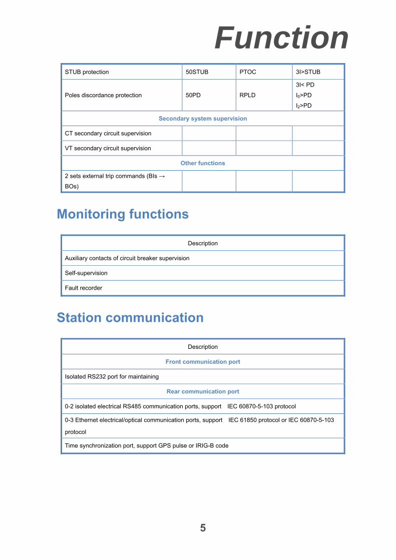
Function
5
STUB protection 50STUB PTOC 3I>STUB
Poles discordance protection 50PD RPLD
3I< PD
I0>PD
I2>PD
Secondary system supervision
CT secondary circuit supervision
VT secondary circuit supervision
Other functions
2 sets external trip commands (BIs →
BOs)
Monitoring functions
Description
Auxiliary contacts of circuit breaker supervision
Self-supervision
Fault recorder
Station communication
Description
Front communication port
Isolated RS232 port for maintaining
Rear communication port
0-2 isolated electrical RS485 communication ports, support IEC 60870-5-103 protocol
0-3 Ethernet electrical/optical communication ports, support IEC 61850 protocol or IEC 60870-5-103
protocol
Time synchronization port, support GPS pulse or IRIG-B code
Function
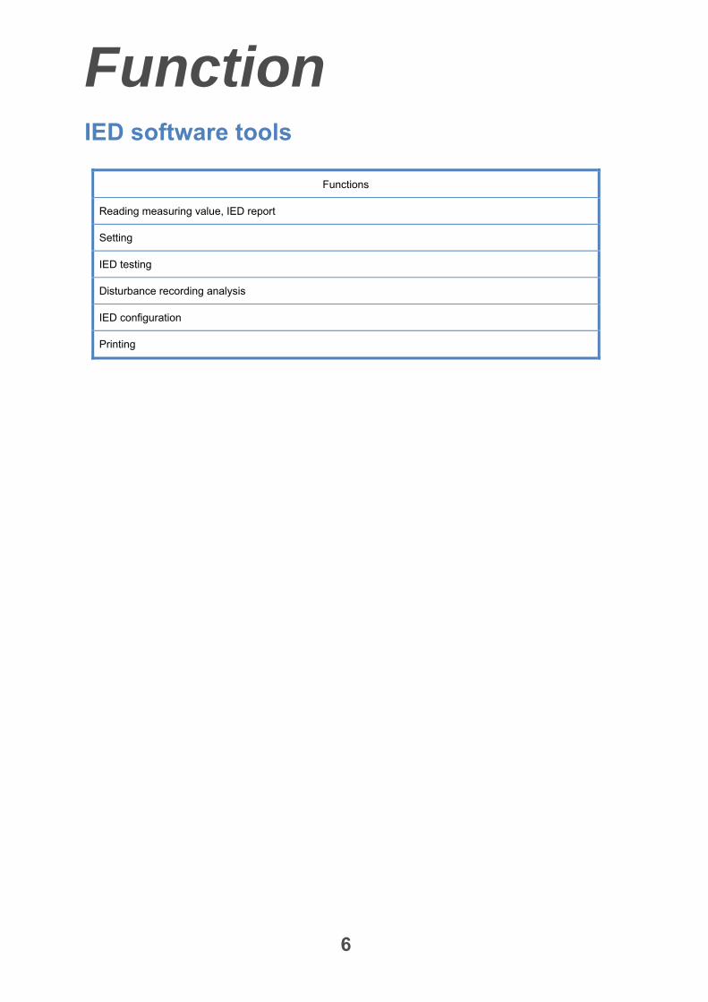
6
IED software tools
Functions
Reading measuring value, IED report
Setting
IED testing
Disturbance recording analysis
IED configuration
Printing
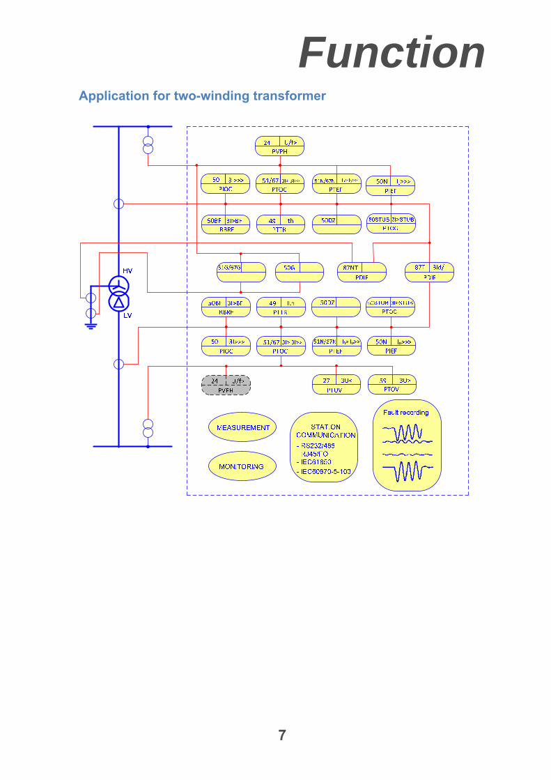
Function
7
Application for two-winding transformer
Function
8
Application for three-winding transformer
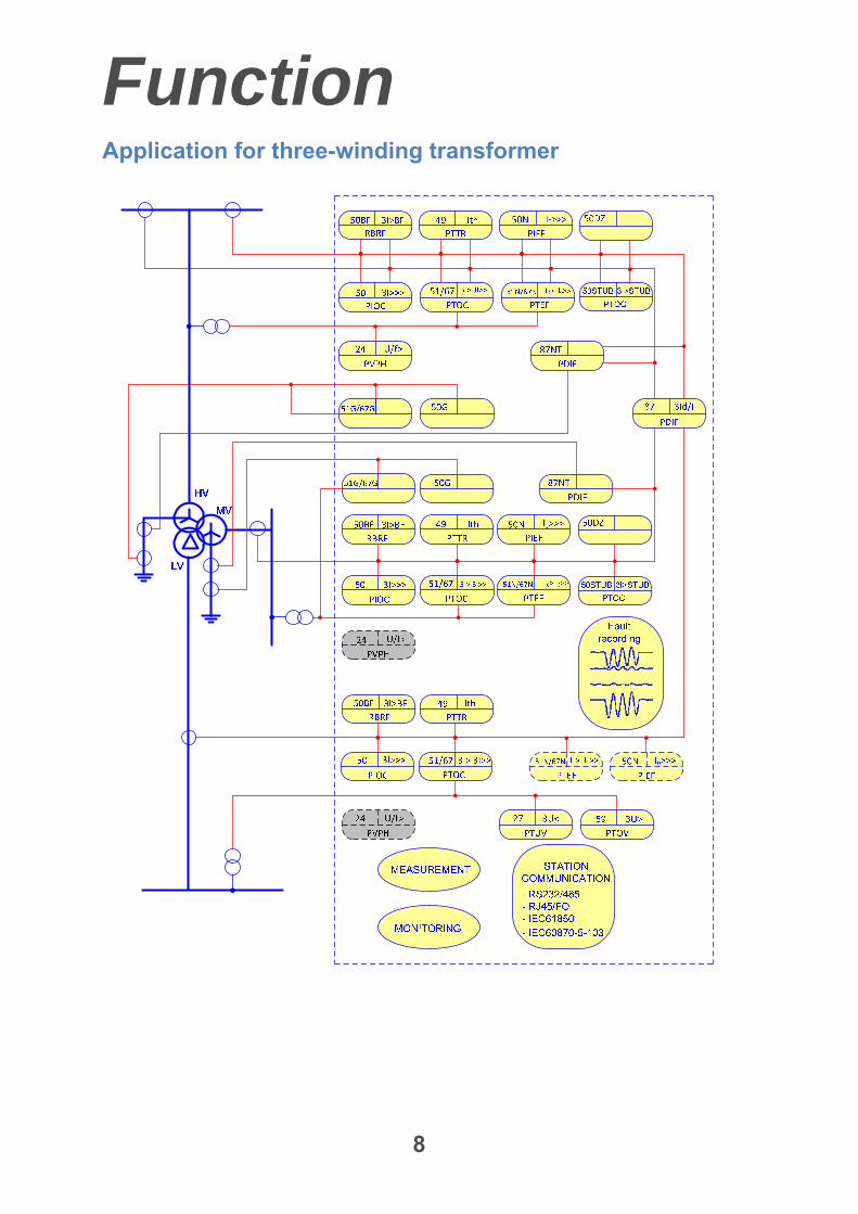
Function
9
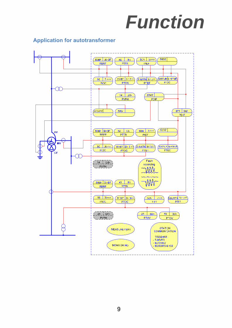
Application for autotransformer
Function
10
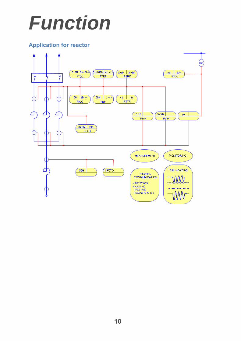
Application for reactor
Protection
11
Transformer differential protection (87T)
The transformer differential protection
function is provided to protect two-winding
transformer, three-winding transformer and
auto-transformer in various configurations
up to 1000 kV voltage level, with internal
CT ratio matching, vector group and zero
sequence current compensation. The
following features would be applied:
Operating characteristic
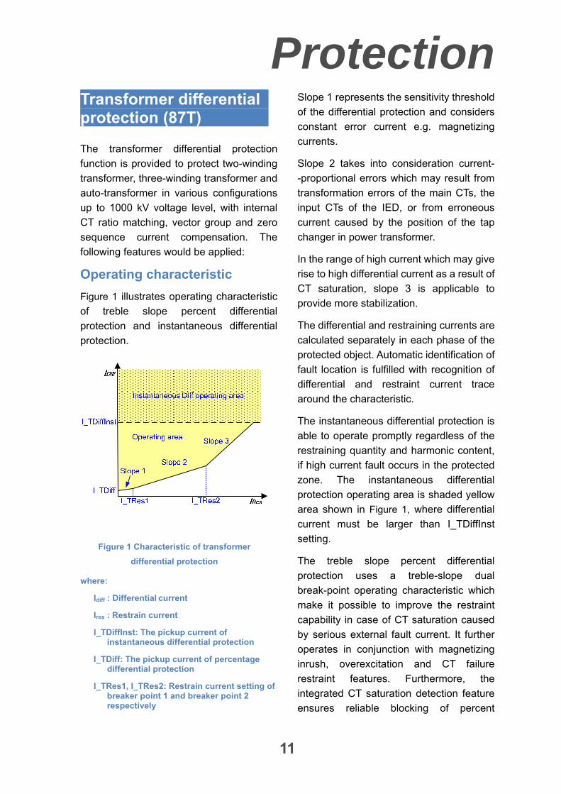
Figure 1 illustrates operating characteristic
of treble slope percent differential
protection and instantaneous differential
protection.
Figure 1 Characteristic of transformer
differential protection
where:
Idiff : Differential current
Ires : Restrain current
I_TDiffInst: The pickup current of instantaneous differential protection
I_TDiff: The pickup current of percentage differential protection
I_TRes1, I_TRes2: Restrain current setting of breaker point 1 and breaker point 2 respectively
Slope 1 represents the sensitivity threshold
of the differential protection and considers
constant error current e.g. magnetizing
currents.
Slope 2 takes into consideration current-
-proportional errors which may result from
transformation errors of the main CTs, the
input CTs of the IED, or from erroneous
current caused by the position of the tap
changer in power transformer.
In the range of high current which may give
rise to high differential current as a result of
CT saturation, slope 3 is applicable to
provide more stabilization.
The differential and restraining currents are
calculated separately in each phase of the
protected object. Automatic identification of
fault location is fulfilled with recognition of
differential and restraint current trace
around the characteristic.
The instantaneous differential protection is
able to operate promptly regardless of the
restraining quantity and harmonic content,
if high current fault occurs in the protected
zone. The instantaneous differential
protection operating area is shaded yellow
area shown in Figure 1, where differential
current must be larger than I_TDiffInst
setting.
The treble slope percent differential
protection uses a treble-slope dual
break-point operating characteristic which
make it possible to improve the restraint
capability in case of CT saturation caused
by serious external fault current. It further
operates in conjunction with magnetizing
inrush, overexcitation and CT failure
restraint features. Furthermore, the
integrated CT saturation detection feature
ensures reliable blocking of percent
Protection
12
differential protection in the case of CT
saturation caused by external fault. At the
same time, severe internal fault can cause
fast protection tripping.
Automatic ratio compensation
The input currents of the IED are converted
automatically in relation to the power
transformer rated currents to be matched
with each other. As a result, matching to
various power transformer and CT ratios is
performed purely mathematically inside the
IED and no external matching CT is
required.
Automatic vector group and zero sequence current compensation
Transformers have different vector groups,
which cause a shift of the phase angles
between the currents flowing through their
high medium and low voltage sides.
Without adequate correction, this phase
shift would cause a false differential current.
Furthermore, the existence of the neutral
point(s) of the power transformer has a
great impact on the differential current
during through fault currents.
The IED is capable to automatically
compensate for the adverse effect of
various vector groups of power trans-
-formers as well as the zero sequence
current which may flow into the protected
zone, depending on the condition of the
neutral point(s). This is achieved just by
informing the IED about the vector group of
the power transformer, and then, all
necessary compensations would be per-
-formed automatically by using coefficient
matrices programmed inside the IED. This
simplifies application of the IED in various
configurations.
Inrush restraint
This feature is provided in the IED to
prevent percent differential protection from
false tripping caused by high short-time
magnetizing currents which may be
present during transformer energizing
(inrush currents).
Two algorithms are available in the IED to
detect inrush conditions. The first one
operates based on 2nd harmonic stabiliza-
-tion, whereas the second algorithm
utilizes fuzzy wave recognition of inrush
conditions based on the current waveform.
Furthermore, a cross blocking feature is
provided which can be used to set the
protection in a way that when the 2nd
harmonic recognition is fulfilled only in one
phase, not only the phase with the inrush
current, but also the remaining phases of
percent differential protection are blocked
for a certain duration as well.
Overexcitation restraint
Stabilization of percent differential
protection function is provided against
unwanted differential currents caused by
transformer overexcitation. Since steady
state overexcitation is characterized by
odd harmonics, the 3rd or the 5th harmonic
can be selected in the IED to recognize for
overexcitation condition.
Current transformer saturation supervision
This integrated function is capable to
recognize CT saturation. CT saturation can
be detected when both the 2nd and 3rd
harmonic contents of phase currents
amongst all phase currents are more than
a threshold. If the CT saturation occurs
simultaneously with external fault
Protection
13
recognition, differential protection will be
blocked.
Differential current supervision
In normal operation condition, zero
differential current is expected in each
phase. The differential current supervision
monitors the differential current of each
phase. An alarm report will be given, if the
differential current exceeds the threshold
value for a delay time.
Reactor differential protection (87R)
The reactor differential protection function
is provided to protect shunt reactor in
various configurations up to 1000 kV
voltage level, with internal CT ratio
matching. The following features would be
applied:
Operating characteristic
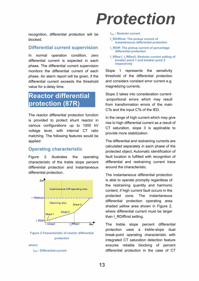
Figure 2 illustrates the operating
characteristic of the treble slope percent
differential protection and instantaneous
differential protection.
Figure 2 Characteristic of reactor differential
protection
where:
Idiff : Differential current
Ires : Restrain current
I_RDiffInst: The pickup current of instantaneous differential protection
I_RDiff: The pickup current of percentage differential protection
I_RRes1, I_RRes2: Restrain current setting of breaker point 1 and breaker point 2 respectively
Slope 1 represents the sensitivity
threshold of the differential protection
and considers constant error current e.g.
magnetizing currents.
Slope 2 takes into consideration current-
-proportional errors which may result
from transformation errors of the main
CTs and the input CTs of the IED.
In the range of high current which may give
rise to high differential current as a result of
CT saturation, slope 3 is applicable to
provide more stabilization.
The differential and restraining currents are
calculated separately in each phase of the
protected object. Automatic identification of
fault location is fulfilled with recognition of
differential and restraining current trace
around the characteristic.
The instantaneous differential protection
is able to operate promptly regardless of
the restraining quantity and harmonic
content, if high current fault occurs in the
protected zone. The instantaneous
differential protection operating area
shaded yellow area shown in Figure 2,
where differential current must be larger
than I_RDiffInst setting.
The treble slope percent differential
protection uses a treble-slope dual
break-point operating characteristic with
integrated CT saturation detection feature
ensures reliable blocking of percent
differential protection in the case of CT
Protection
14
saturation caused by external fault. At the
same time, severe internal fault can cause
fast protection tripping.
Automatic ratio compensation
The input currents of the IED are converted
automatically in relation to the shunt
reactor rated currents to be matched with
each other. As a result, matching to various
shunt reactor and CT ratios is performed
purely mathematically inside the device
and no external matching CT is required.
Current transformer saturation supervision
This integrated function is capable to
recognize CT saturation. CT saturation can
be detected when both the 2nd and 3rd
harmonic contents of phase currents
amongst all phase currents are more than
a threshold. If the CT saturation occurs
simultaneously with external fault
recognition, differential protection will be
blocked.
Differential current supervision
In normal operation condition, zero
differential current is expected in each
phase. The differential current supervision
monitors the differential current of each
phase. An alarm report will be given, if the
differential current exceeds the threshold
value for a delay time.
Restricted earth fault protection for transformer (87NT)
The REF protection provides higher
sensitivity and higher speed when they
measure individually on each winding.
They are capable to detect earth faults in
(auto) transformer earthed. A precondition
for using these functions is that a neutral
CT should be provided.
Operating characteristic
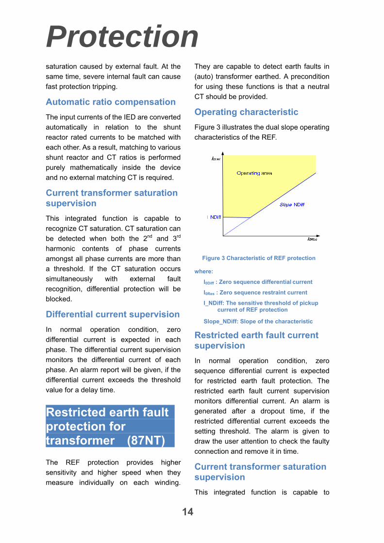
Figure 3 illustrates the dual slope operating
characteristics of the REF.
Figure 3 Characteristic of REF protection
where:
I0Diff : Zero sequence differential current
I0Res : Zero sequence restraint current
I_NDiff: The sensitive threshold of pickup current of REF protection
Slope_NDiff: Slope of the characteristic
Restricted earth fault current supervision
In normal operation condition, zero
sequence differential current is expected
for restricted earth fault protection. The
restricted earth fault current supervision
monitors differential current. An alarm is
generated after a dropout time, if the
restricted differential current exceeds the
setting threshold. The alarm is given to
draw the user attention to check the faulty
connection and remove it in time.
Current transformer saturation supervision
This integrated function is capable to
Protection
15
recognize CT saturation. In this situation,
CT saturation is detected when both the
2nd and 3rd harmonic components of
phase currents amongst all phase currents
are more than a threshold. Using these
measurements, if the CT saturation occurs
simultaneous with external fault
recognition, the restricted earth fault
protection will be blocked.
Difference of transient characteristic of CTs detection
Difference of transient characteristic of
phase or neutral CTs may result in
zero-sequence current in REF protection
during an external three-phase fault. To
remove this problem, the situation is
detected by using the calculated positive
and zero-sequence currents. The condition
is checked for each side of transformer
separately.
Restricted earth fault protection for reactor (87NR)
The REF protection provides higher
sensitivity and higher speed when they
measure individually on each winding.
They are capable to detect earth faults in
reactor earthed.
Operating characteristic
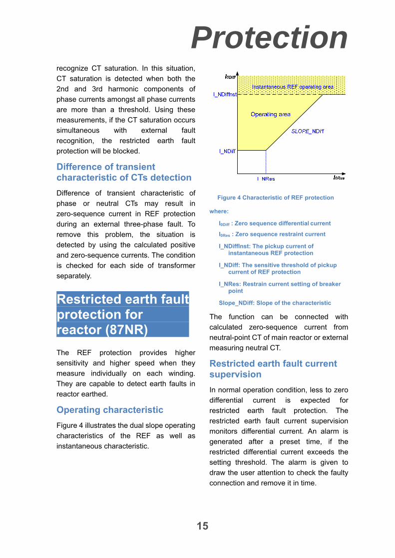
Figure 4 illustrates the dual slope operating
characteristics of the REF as well as
instantaneous characteristic.
Figure 4 Characteristic of REF protection
where:
I0Diff : Zero sequence differential current
I0Res : Zero sequence restraint current
I_NDiffInst: The pickup current of instantaneous REF protection
I_NDiff: The sensitive threshold of pickup current of REF protection
I_NRes: Restrain current setting of breaker point
Slope_NDiff: Slope of the characteristic
The function can be connected with
calculated zero-sequence current from
neutral-point CT of main reactor or external
measuring neutral CT.
Restricted earth fault current supervision
In normal operation condition, less to zero
differential current is expected for
restricted earth fault protection. The
restricted earth fault current supervision
monitors differential current. An alarm is
generated after a preset time, if the
restricted differential current exceeds the
setting threshold. The alarm is given to
draw the user attention to check the faulty
connection and remove it in time.
Protection
16
Current transformer saturation supervision
This integrated function is capable to
recognize CT saturation, if calculated zero
sequence current is used from neutral side
CT of the main reactor, instead measured
value from the dedicated neutral CT. In this
situation, CT saturation is detected when
both the 2nd and 3rd harmonic components
of phase currents amongst all phase
currents are more than a threshold. Using
these measurements, if the CT saturation
occurs simultaneous with external fault
recognition, the restricted earth fault
protection will be blocked.
Interturn fault protection (16)
The inter-turn fault protection detects faults
between reactor winding turns. A short
circuit of a few turns of the winding will give
rise to a heavy fault current in the
short-circuited loop, but the terminal
currents will be very small, because of the
high ratio of transformation between the
whole winding and the short-circuited turns.
Therefore, the short circuited turns can be
damaged by large short circuit current. In
this case, partial winding flashover is more
likely and the subsequent progress of the
fault, if not detected in the earliest fault
stage, may severely destroy the object.
The inter-turn fault protection in the IED
uses zero-sequence component direction
using zero-sequence current in neutral-
-point of the main reactor and the
calculated zero-sequence voltage at the
HV terminal of the reactor.
When there is inter-turn short-circuit inside
the reactor, the zero-sequence voltage
leads the zero-sequence current. However,
for an external fault, the corresponding
zero-sequence voltage will lag the
zero-sequence current. So, the phase-
-angle relation is used to distinguish the
internal or external fault of the reactor.
Overcurrent protection (50, 51, 67)
The protection provides following
features:
Two definite time stages
One inverse time stage
11 kinds of IEC and ANSI inverse time
characteristic curves as well as
optional user defined characteristic
Selectable directional element charac-
-teristic angle, to satisfy the different
network conditions and applications
Each stage can be set individually as
directional/non-directional
Directional element can be set to point
protected object or system for all
stages
Each stage can be set individually for
inrush restraint
Cross blocking function for inrush
detection
Settable maximum inrush current
VT secondary circuit supervision for
directional protection. Once VT failure
happens, the directional stage can be
set to be blocked or to be
non-directional
Inrush restraint function
Protection
17
The protection relay may detect large
magnetizing inrush currents during
transformer energizing. In addition to
considerable unbalance fundamental
current, Inrush current comprises large
second harmonic current which doesn’t
appear in short circuit current. Therefore,
the inrush current may affect the protection
functions which operate based on the
fundamental component of the measured
current. Accordingly, inrush restraint logic
is provided to prevent overcurrent
protection from maloperation.
Furthermore, by recognition of the inrush
current in one phase, it is possible to set
the protection in a way that not only the
phase with the considerable inrush current,
but also the other phases of the
overcurrent protection are blocked for a
certain time. This is achieved by
cross-blocking feature integrated in the
IED.
The inrush restraint function has a
maximum inrush current setting. Once
the measuring current exceeds the
setting, the overcurrent protection will not
be blocked any longer.
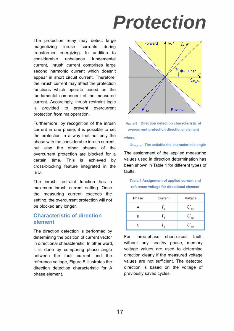
Characteristic of direction element
The direction detection is performed by
determining the position of current vector
in directional characteristic. In other word,
it is done by comparing phase angle
between the fault current and the
reference voltage, Figure 5 illustrates the
direction detection characteristic for A
phase element.
Figure 5 Direction detection characteristic of
overcurrent protection directional element
where:
ФPh_Char: The settable the characteristic angle
The assignment of the applied measuring
values used in direction determination has
been shown in Table 1 for different types of
faults.
Table 1 Assignment of applied current and
reference voltage for directional element
Phase Current Voltage
A aI bcU
B bI caU
C cI abU
For three-phase short-circuit fault,
without any healthy phase, memory
voltage values are used to determine
direction clearly if the measured voltage
values are not sufficient. The detected
direction is based on the voltage of
previously saved cycles.
Protection
18
Earth fault protection (50N, 51N, 67N)
The earth fault protection can be used to
clear phase to earth faults as system
back-up protection.
The protection provides following
features:
Two definite time stages
One inverse time stage
11 kinds of the IEC and ANSI inverse
time characteristic curves as well as
optional user defined characteristic
Zero sequence directional element
Each stage can be set individually as
directional/non-directional
Directional element can be set to be
forward toward the protected object or
reverse toward system for all stage
Settable directional element
characteristic angle, to satisfy the
different network conditions and
applications
Each stage can be set individually for
inrush restraint
Settable maximum inrush current
Inrush restraint function adopting 2nd
harmonic measured phase or earth
current settable
VT secondary circuit supervision for
directional protection function. Once
VT failure happens, the directional
stage can be set to be blocked or to be
non-directional
Zero-sequence current is calculated by
summation of 3 phase currents
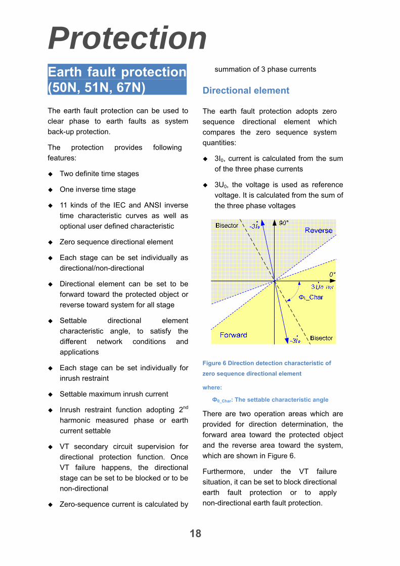
Directional element
The earth fault protection adopts zero
sequence directional element which
compares the zero sequence system
quantities:
3I0, current is calculated from the sum
of the three phase currents
3U0, the voltage is used as reference
voltage. It is calculated from the sum of
the three phase voltages
Figure 6 Direction detection characteristic of
zero sequence directional element
where:
Ф0_Char: The settable characteristic angle
There are two operation areas which are
provided for direction determination, the
forward area toward the protected object
and the reverse area toward the system,
which are shown in Figure 6.
Furthermore, under the VT failure
situation, it can be set to block directional
earth fault protection or to apply
non-directional earth fault protection.
Protection
19
Inrush restraint function
The protection relay may detect large
magnetizing inrush currents during
transformer energizing. In addition to
considerable unbalance fundamental
current, Inrush current comprises large
second harmonic current which doesn’t
appear in short circuit current. Therefore,
the inrush current may affect the protection
functions which operate based on the
fundamental component of the measured
current. Accordingly, inrush restraint logic
is provided to prevent earth fault protection
from mis-tripping.
Since inrush current cannot be more than a
specified value, the inrush restraint
provides an upper current limit in which
blocking does not occur.
Neutral earth fault protection (50G, 51G 67G)
The neutral earth fault protection focus
on phase to earth faults. The measuring
current is one phase current from
dedicated neutral CT.
The protection function provides following
features:
Two definite time stages
One inverse time stage
11 kinds of the IEC and ANSI inverse
time characteristic curves as well as
optional user defined characteristic
Each stage can be set to be
directional/non-directional
independently
Zero sequence directional element. Its
characteristic is same as earth fault
protection illustrated in Figure 6
Directional element can be set to be
forward toward the protected object or
reverse toward system for all stages
Setable directional element
characteristic angle, to satisfy the
different network conditions and
applications
Inrush restraint function can be set for
each stage separately
Settable maximum inrush current
VT secondary circuit supervision for
directional protection function
Neutral current is measured from
dedicated neutral CT
Inrush restraint feature
The neutral earth fault protection may
detect large magnetizing inrush currents
flowing when transformer is energized.
Directional element
Directional determination of neutral earth
fault element adopts the zero sequence
directional element as same as the one
applied by earth fault protection. The only
difference is the measured current, which
is measured from the neutral point CT
instead of being calculated from three
phase currents.
Thermal overload protection (49)
The insulating material surrounding the

Protection
20
windings ages rapidly if the temperature
exceeds the design limit value. Thus, a
thermal protection function is required to
supplement the existing winding
temperature device. The thermal
overload protection estimates winding
temperature and thus prevents it from
thermal damaging.
The thermal overload protection operates
based on an approximate replica of the
temperature rise in the protected object
caused by overload.
The thermal replica can be implemented
based on thermal models (Cold or Hot
Curve) of IEC60255-8 standard.
The thermal overload in the IED is
provided with one trip stage as well as one
alarm stage. It is possible to set the alarm
stage at a certain percentage of the setting
value applied at the trip stage.
The calculation is performed separately for
each phase, based on fundamental
component and harmonic components.
Overload protection (50OL)
The IED supervises load flow in real time.
If each phase current is greater than the
dedicated setting for a set delay time, the
protection will issue alarm.
Transformer delta winding overload protection (50OL)
When there is a dedicated CT for each
phase of the transformer delta winding,
the protection is provided to monitor the
load flow in real time. If all three phase
current are always greater than the
setting of power swing for a setting time,
the alarm will be reported.
Overexcitation protection (24)
The IED provides an overexcitation
protection to detect impermissible over-
-excitation conditions which can
endanger power transformers as a result
of saturation in iron core and resulting
large eddy current losses which may
lead to impermissible temperature rise
inside the transformer core.
The function measures the voltage
/frequency (U/f) ratio which is
proportional to the flux density in
transformer core.
One definite time stage for alarm
One definite time stage for trip
One thermal overexcitation time
characteristic stage, which can be
defined by user-defined settings (see
Figure 7
Figure 7 Thermal overexcitation time
characteristic
Protection
21
Overvoltage protection (59)
One voltage rise occur possibly in the
power system during abnormal conditions
such as no-load, lightly load, or open line
end on long line. The protection can be
used as open line end detector or as
system voltage supervision normally.
The protection provides following features:
Two definite time stages
First stage can be set to alarm or trip
Measuring voltage between phase-
-earth voltage and phase-phase
selectable
Settable dropout ratio
Undervoltage protection (27)
One voltage reduction can occur in the
power system during faults or abnormal
conditions.
The protection provides following
features:
Two definite time stages
First stage can be set to alarm or trip
Measuring voltage between phase-
-earth voltage and phase-phase
selectable
Current criteria supervision
Circuit breaker aux. contact super-
-vision
VT secondary circuit supervision, the
undervoltage function will be blocked
when VT failure happens
Settable dropout ratio
Zero sequence over- -voltage protection (64)
The zero sequence overvoltage
protection is able to monitor the voltage
displacement to detect the earth fault in
power system.
The displacement voltage 3U0 can be
either directly measured from VT or
calculated based on connected three
phases to earth voltages. In the latter
case, the three voltages transformers
input must be connected in an earth-wye
configuration.
The protection provide following
features:
Two definite time stages
3U0 based on calculated summation of
3 phase voltage or measured injected
residual voltage
Breaker failure protection (50BF)
The circuit breaker failure protection is
able to detect a failure of the circuit
breaker during a fault clearance. It
ensures fast back-up tripping of
surrounding breakers by tripping relevant
bus sections.
The protection can be three-phase
started to allow use with three phase
tripping applications.
Once a circuit breaker operating failure
occurs on a feeder/transformer, the bus
Protection
22
section which the feeder/transformer is
connected with can be selectively
isolated by the protection. In addition a
The CBs of the other windings of the
transformer are tripped at the same time.
In the event of a circuit breaker failure
with a busbar fault, a trip signal is issued
to trip the CBs of the other windings of
the transformer.
The current criteria are in combination
with three phase current, zero and
negative sequence current to achieve a
higher security.
The function can be set to give three phase
re-tripping of the local breaker to avoid
unnecessary tripping of surrounding
breakers in the case of two available trip
coils.
Two trip stages (local and surrounding
breaker tripping)
Internal/ external initiation
Selectable CB Aux contacts checking
Current criteria checking (including
phase current, zero and negative
sequence current)
Dead zone protection (50DZ)
The IED provides this protection function
to protect dead zone, namely the area
between circuit breaker and CT in the
case that CB is open. Therefore, by
occurrence of a fault in dead zone, the
short circuit current is measured by
protection relay while CB auxiliary
contacts indicate the CB is open.
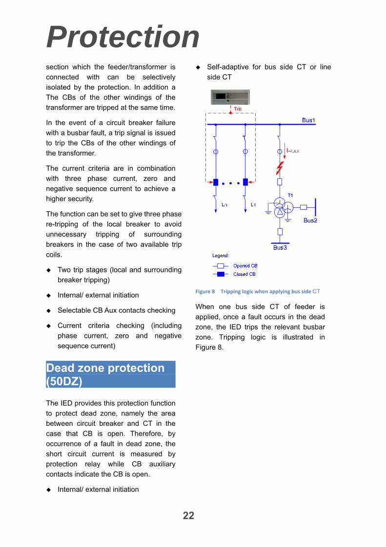
Internal/ external initiation
Self-adaptive for bus side CT or line
side CT
Figure 8 Tripping logic when applying bus side CT
When one bus side CT of feeder is
applied, once a fault occurs in the dead
zone, the IED trips the relevant busbar
zone. Tripping logic is illustrated in
Figure 8.
Protection
23
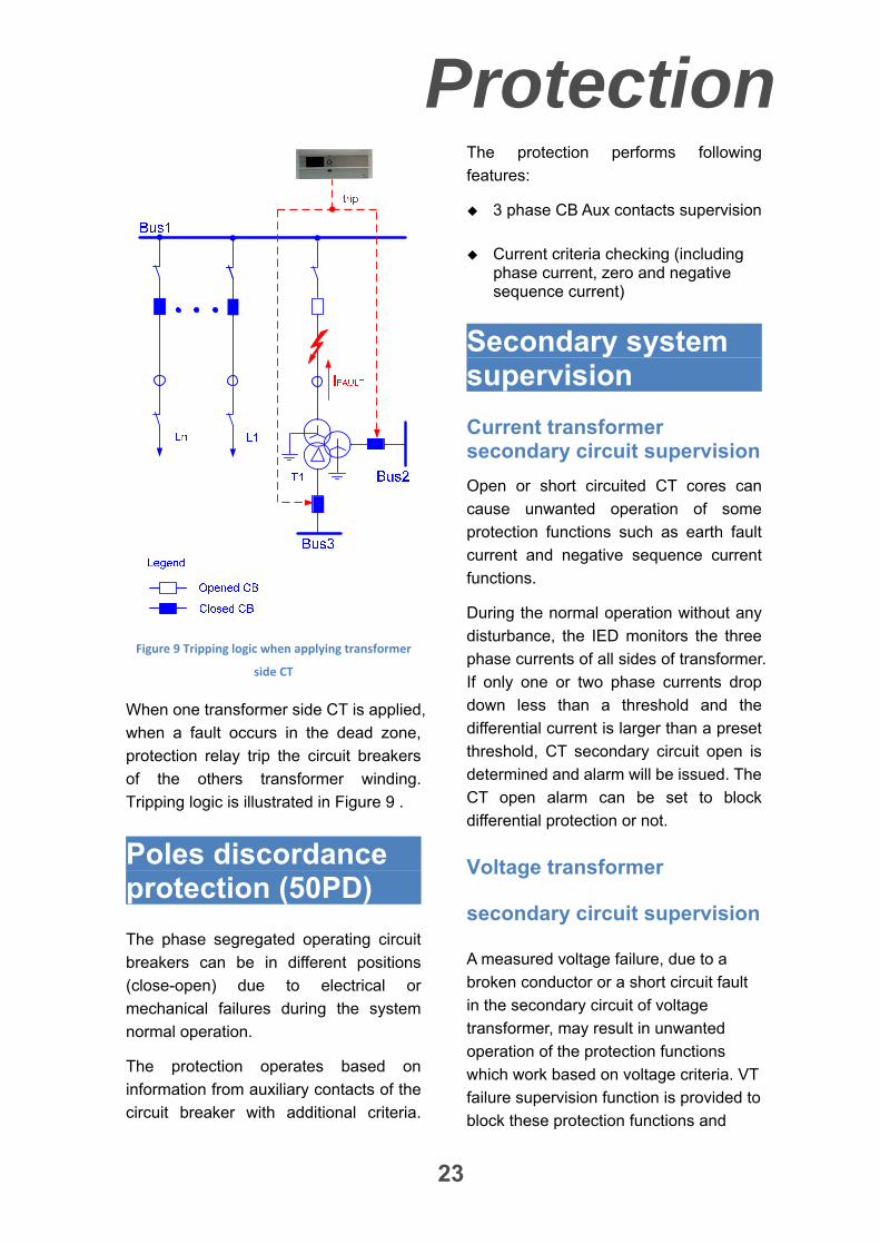
Figure 9 Tripping logic when applying transformer
side CT
When one transformer side CT is applied,
when a fault occurs in the dead zone,
protection relay trip the circuit breakers
of the others transformer winding.
Tripping logic is illustrated in Figure 9 .
Poles discordance protection (50PD)
The phase segregated operating circuit
breakers can be in different positions
(close-open) due to electrical or
mechanical failures during the system
normal operation.
The protection operates based on
information from auxiliary contacts of the
circuit breaker with additional criteria.
The protection performs following
features:
3 phase CB Aux contacts supervision
Current criteria checking (including phase current, zero and negative sequence current)
Secondary system supervision
Current transformer secondary circuit supervision
Open or short circuited CT cores can
cause unwanted operation of some
protection functions such as earth fault
current and negative sequence current
functions.
During the normal operation without any
disturbance, the IED monitors the three
phase currents of all sides of transformer.
If only one or two phase currents drop
down less than a threshold and the
differential current is larger than a preset
threshold, CT secondary circuit open is
determined and alarm will be issued. The
CT open alarm can be set to block
differential protection or not.
Voltage transformer
secondary circuit supervision
A measured voltage failure, due to a
broken conductor or a short circuit fault
in the secondary circuit of voltage
transformer, may result in unwanted
operation of the protection functions
which work based on voltage criteria. VT
failure supervision function is provided to
block these protection functions and
Protection
24
enable the backup protection functions.
The features of the function are as
follows:
Symmetrical/asymmetrical VT failure
detection
3-phase AC voltage MCB monitoring
1-phase AC voltage MCB monitoring
Zero and negative sequence current
monitoring
Applicable in solid grounded,
compensated or isolated networks

Monitoring
25
Self-supervision
All modules can perform self-
-supervision to its key hardware
components and program, as soon as
energizing. Parts of the modules are
self-supervised in real time. All internal
faults or abnormal conditions will
initiate an alarm. The fatal faults among
them will result in the whole IED
blocked
CPU module and communication
module perform real time inter-
-supervision. Therefore communication
interruption between them is detected
and related alarm will be given
CRC code checks for the setting,
program and configuration, etc.
Communication
26
Station communication
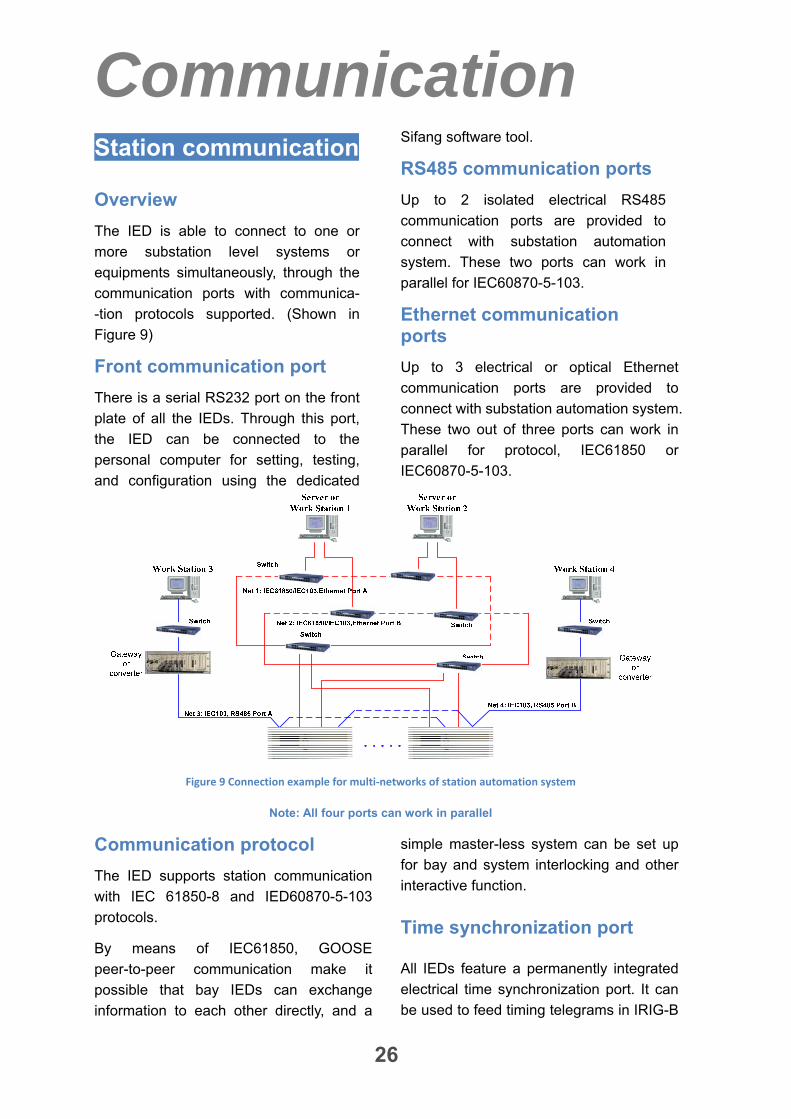
Overview
The IED is able to connect to one or
more substation level systems or
equipments simultaneously, through the
communication ports with communica-
-tion protocols supported. (Shown in
Figure 9)
Front communication port
There is a serial RS232 port on the front
plate of all the IEDs. Through this port,
the IED can be connected to the
personal computer for setting, testing,
and configuration using the dedicated
Sifang software tool.
RS485 communication ports
Up to 2 isolated electrical RS485
communication ports are provided to
connect with substation automation
system. These two ports can work in
parallel for IEC60870-5-103.
Ethernet communication ports
Up to 3 electrical or optical Ethernet
communication ports are provided to
connect with substation automation system.
These two out of three ports can work in
parallel for protocol, IEC61850 or
IEC60870-5-103.
Figure 9 Connection example for multi‐networks of station automation system
Note: All four ports can work in parallel
Communication protocol
The IED supports station communication
with IEC 61850-8 and IED60870-5-103
protocols.
By means of IEC61850, GOOSE
peer-to-peer communication make it
possible that bay IEDs can exchange
information to each other directly, and a
simple master-less system can be set up
for bay and system interlocking and other
interactive function.
Time synchronization port
All IEDs feature a permanently integrated
electrical time synchronization port. It can
be used to feed timing telegrams in IRIG-B
Communication
27
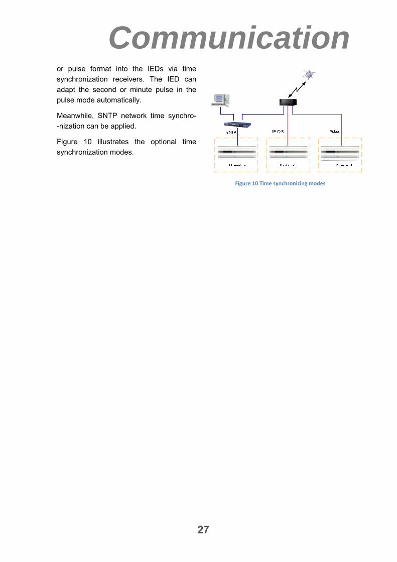
or pulse format into the IEDs via time
synchronization receivers. The IED can
adapt the second or minute pulse in the
pulse mode automatically.
Meanwhile, SNTP network time synchro-
-nization can be applied.
Figure 10 illustrates the optional time
synchronization modes.
Figure 10 Time synchronizing modes
So
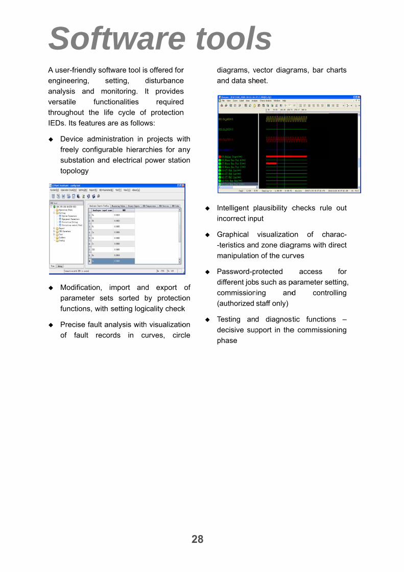
A user-f
enginee
analysis
versatile
through
IEDs. Its
Dev
free
subs
topo
Mod
para
func
Prec
of
oftfriendly soft
ering, se
s and mo
e funct
hout the life
s features a
vice adminis
ly configura
station and
ology
dification,
ameter set
ctions, with
cise fault an
fault reco
twatware tool is
etting, d
onitoring. I
tionalities
e cycle of
are as follow
stration in
able hierarc
electrical p
import and
ts sorted b
setting logi
nalysis with
ords in cu
ares offered for
disturbance
t provides
required
f protection
ws:
projects w
chies for a
power statio
d export
by protectio
cality check
h visualizatio
urves, circ
e to
28
r
e
s
d
n
ith
ny
on
of
on
k
on
cle
d
a
I
i
G
-
m
P
d
c
(
T
d
p
oolsdiagrams, v
and data sh
ntelligent p
ncorrect inp
Graphical
-teristics and
manipulatio
Password-p
different job
commission
(authorized
Testing and
decisive sup
phase
ls
vector diagr
eet.
plausibility c
put
visualizatio
d zone diag
n of the cur
protected
s such as p
ing and
staff only)
d diagnost
pport in the
rams, bar c
checks rule
on of ch
grams with
rves
access
parameter s
d contr
tic functio
e commissi
charts
e out
harac-
direct
for
etting,
rolling
ns –
oning
Hardware
29
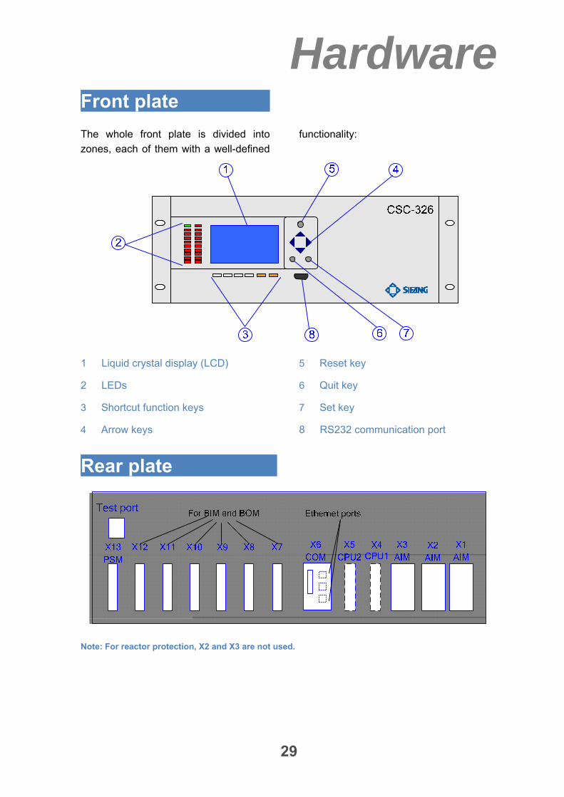
Front plate
The whole front plate is divided into
zones, each of them with a well-defined
functionality:
1 Liquid crystal display (LCD)
2 LEDs
3 Shortcut function keys
4 Arrow keys
5 Reset key
6 Quit key
7 Set key
8 RS232 communication port
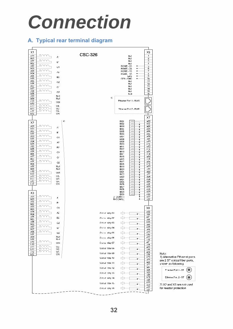
Rear plate
Note: For reactor protection, X2 and X3 are not used.
Hardware
30
Modules
Analogue Input Module (AIM)
The analogue input module is used to
galvanically separate and transform the
secondary currents and voltages
generated by the measuring transformers.
CPU Module (CPU)
The CPU module handles all protection
functions and logic. There are two CPU
modules in the IED, CPU1 and CPU2, with
the same software and hardware. They
work in parallel and interlock each other to
prevent maloperation due to the internal
faults of one CPU modules.
Moreover, the redundant A/D sampling
channels are equipped. By comparing the
data from redundant sampling channels,
any sampling data errors and the channel
hardware faults can be detected
immediately and the proper alarm and
blocking is initiated in time.
Communication Module (COM)
The communication module performs
communication between the internal
protection system and external equipments
such as HMI, engineering workstation,
substation automation system, RTU, etc.,
to transmit remote metering, remote
signaling, SOE, event reports and record
data.
Up to 3 channels isolated electrical or
optical Ethernet ports and up to 2 channels
RS485 serial communication ports can be
provided in communication module to meet
the communication demands of different
substation automation system and RTU at
the same time.
The time synchronization port is equipped,
which can work in pulse mode or IRIG-B
mode. SNTP mode can be applied through
communication port.
In addition, a series printer port is also
reserved.
Binary Input Module (BIM)
The binary input module is used to connect
the input signals and alarm signals such as
the auxiliary contacts of the circuit breaker
(CB), etc.
Binary Output Module (BOM)
The binary output modules mainly provide
tripping output contacts, initiating output
contacts and signaling output contacts. All
the tripping output relays have contacts
with a high switching capacity and are
blocked by protection startup elements.
Each output relay can be configured to
satisfy the demands of users.
Power Supply Module (PSM)
The power supply module is used to
provide the correct internal voltages and
full isolation between the terminal and the
battery system.
Hardware
31
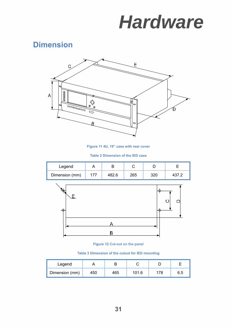
Dimension
Figure 11 4U, 19” case with rear cover
Table 2 Dimension of the IED case
Legend A B C D E
Dimension (mm) 177 482.6 265 320 437.2
Figure 12 Cut-out on the panel
Table 3 Dimension of the cutout for IED mounting
Legend A B C D E
Dimension (mm) 450 465 101.6 178 6.5
Connection
32
A. Typical rear terminal diagram
Connection
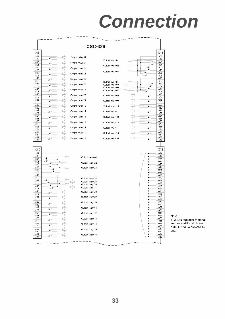
33
Connection
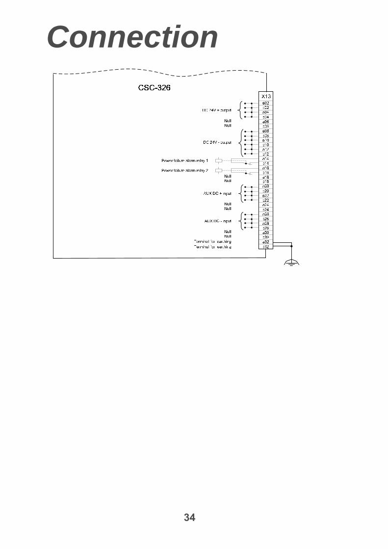
34
Connection
35
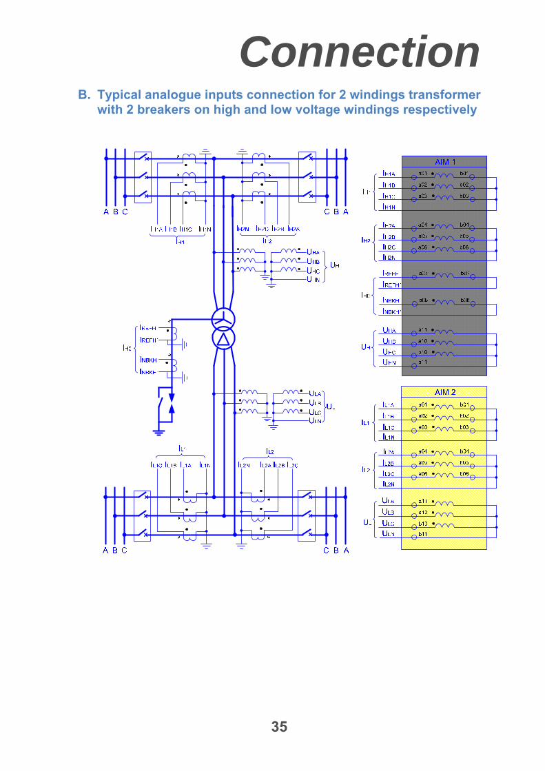
B. Typical analogue inputs connection for 2 windings transformer with 2 breakers on high and low voltage windings respectively
Connection
36
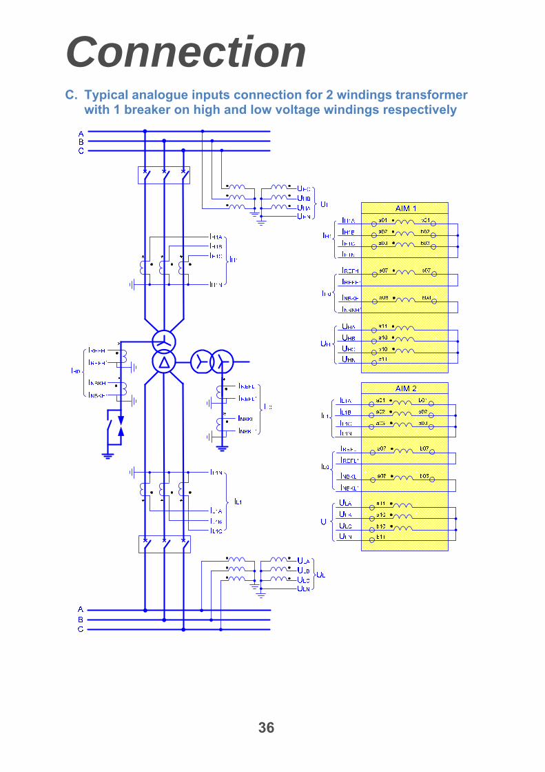
C. Typical analogue inputs connection for 2 windings transformer with 1 breaker on high and low voltage windings respectively
Connection
37
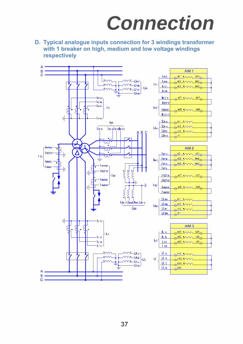
D. Typical analogue inputs connection for 3 windings transformer with 1 breaker on high, medium and low voltage windings respectively
Connection
38
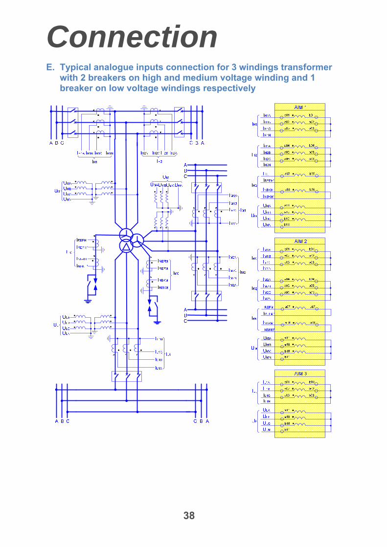
E. Typical analogue inputs connection for 3 windings transformer with 2 breakers on high and medium voltage winding and 1 breaker on low voltage windings respectively
Connection
39
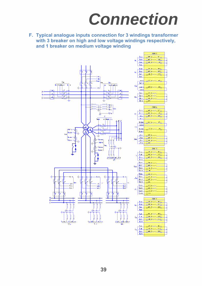
F. Typical analogue inputs connection for 3 windings transformer with 3 breaker on high and low voltage windings respectively, and 1 breaker on medium voltage winding
Connection
40
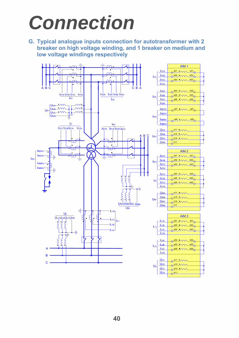
G. Typical analogue inputs connection for autotransformer with 2 breaker on high voltage winding, and 1 breaker on medium and low voltage windings respectively
a01
a02
a03
b01
b02
b03
**
*
*
A B C
**
*
BC
* * *
A
B
C
A
IH1A IH1B IH1C IH2C IH2B IH2A
IH1
IH1
IH2
IH1N
IH1N
a04
a05
a06
b04
b05
b06
IH2N
IH2
a11
a10
b10
UHN
UH
UHA
UHB
UHC
*
UH
UHA
UHB
UHC
IH2N
UHN
a07 b07
a08 b08
IREFH
IH1A
IH1B
IH1C
IH2A
IH2B
IH2C
IREFH
IREFH’
INBKH
INBKH’
IREFH’
INBKH
INBKH’
IL1A
IL1B
IL1C IL1
IL1N
a01
a02
a03
b01
b02
b03IL1
IL1N
a04
a05
a06
b04
b05
b06
IL2N
IL2
IL1A
IL1B
IL1C
IL2A
IL2B
IL2C
a11
a10
b10
ULN
ULA
ULB
ULCUL
b11
b11
IH0
IH0
UL
ULAULBULCUHN
A B C
**
*IM1A IM1B IM1CIM1N
UM
UMAUMBUMC UMN
IM1
a01
a02
a03
b01
b02
b03
IM1N
IM1
a11
a10
b10
UMN
UM
UMA
UMB
UMC
IM1A
IM1B
IM1C
b11
AIM 1
AIM 2
**
*
IG1C IG1BIG1A
IG
IG1N
a04
a05
a06
b04
b05
b06
IG1N
IG1A
IG1B
IG1CIG
AIM 3
Connection
41
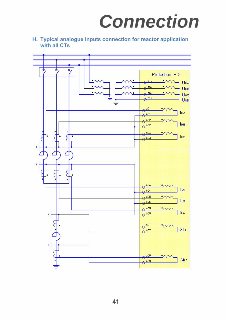
H. Typical analogue inputs connection for reactor application with all CTs
Connection
42
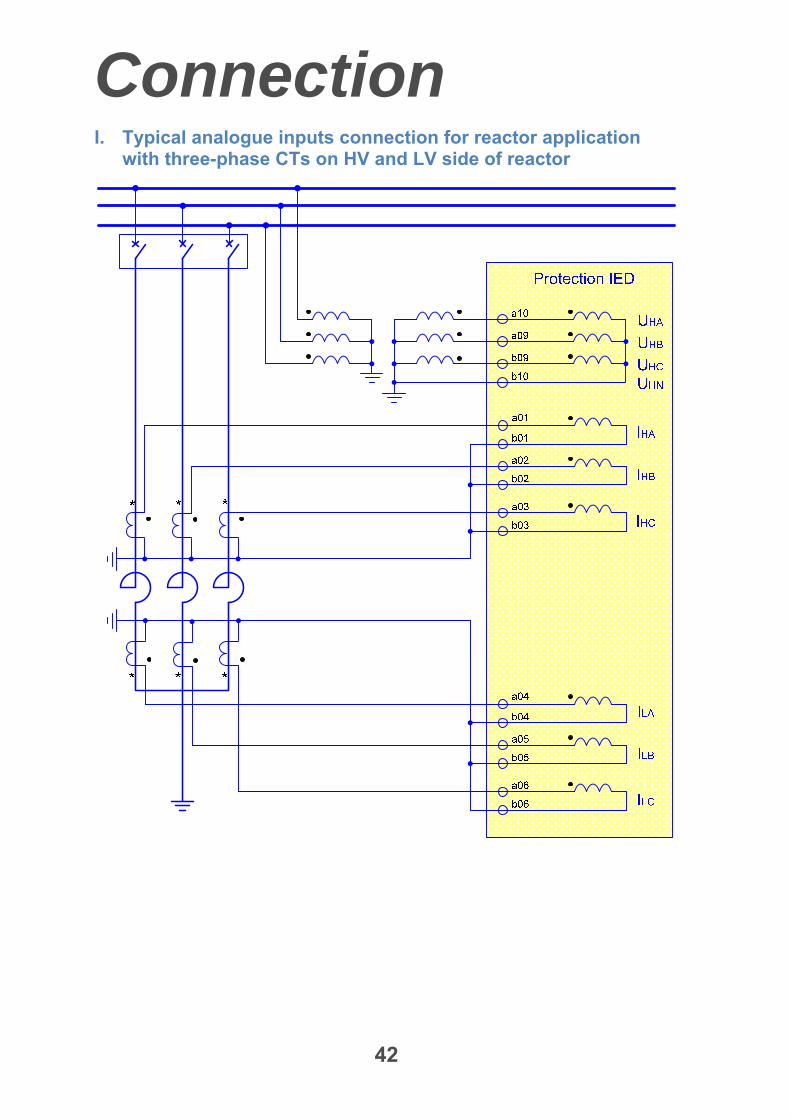
I. Typical analogue inputs connection for reactor application with three-phase CTs on HV and LV side of reactor
Connection
43
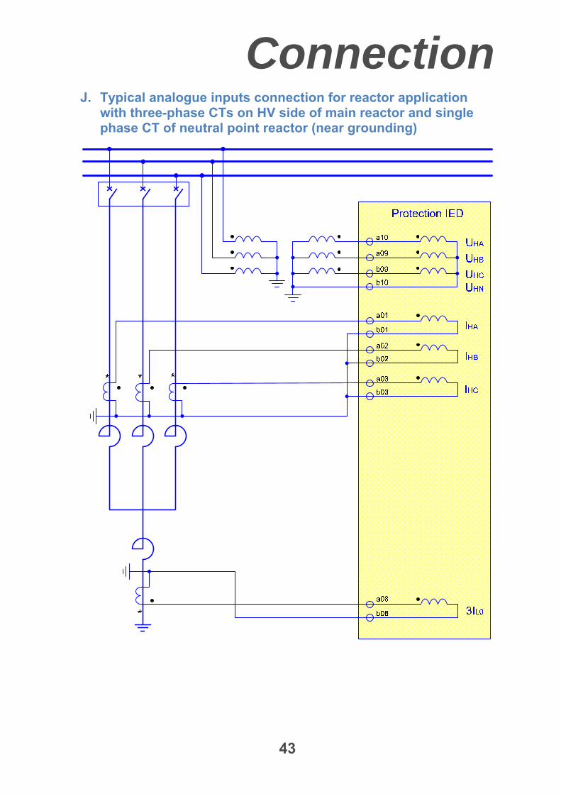
J. Typical analogue inputs connection for reactor application with three-phase CTs on HV side of main reactor and single phase CT of neutral point reactor (near grounding)
Connection
44
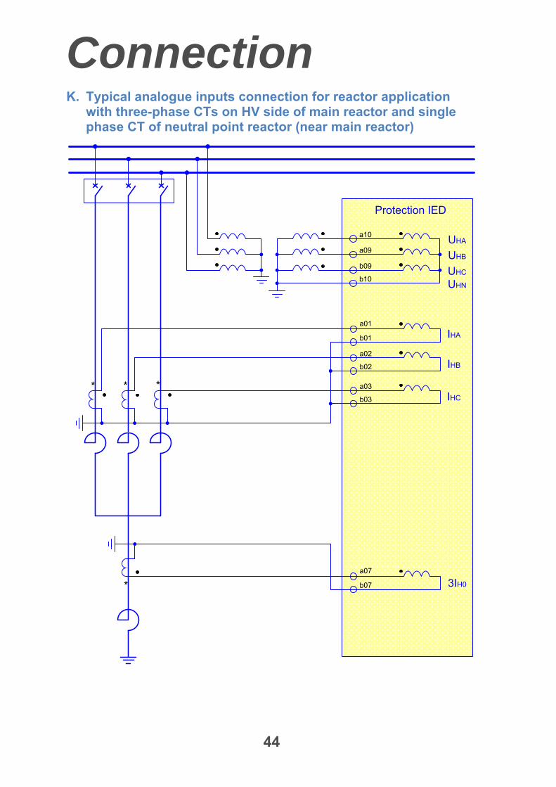
K. Typical analogue inputs connection for reactor application with three-phase CTs on HV side of main reactor and single phase CT of neutral point reactor (near main reactor)
* * *
IHA
IHB
IHC
Protection IED
a01
a02
a03
b01
b02
b03
* 3IH0
a07
b07
UHB
UHA
UHC
UHN
a10
a09
b09
b10
Technical data
45
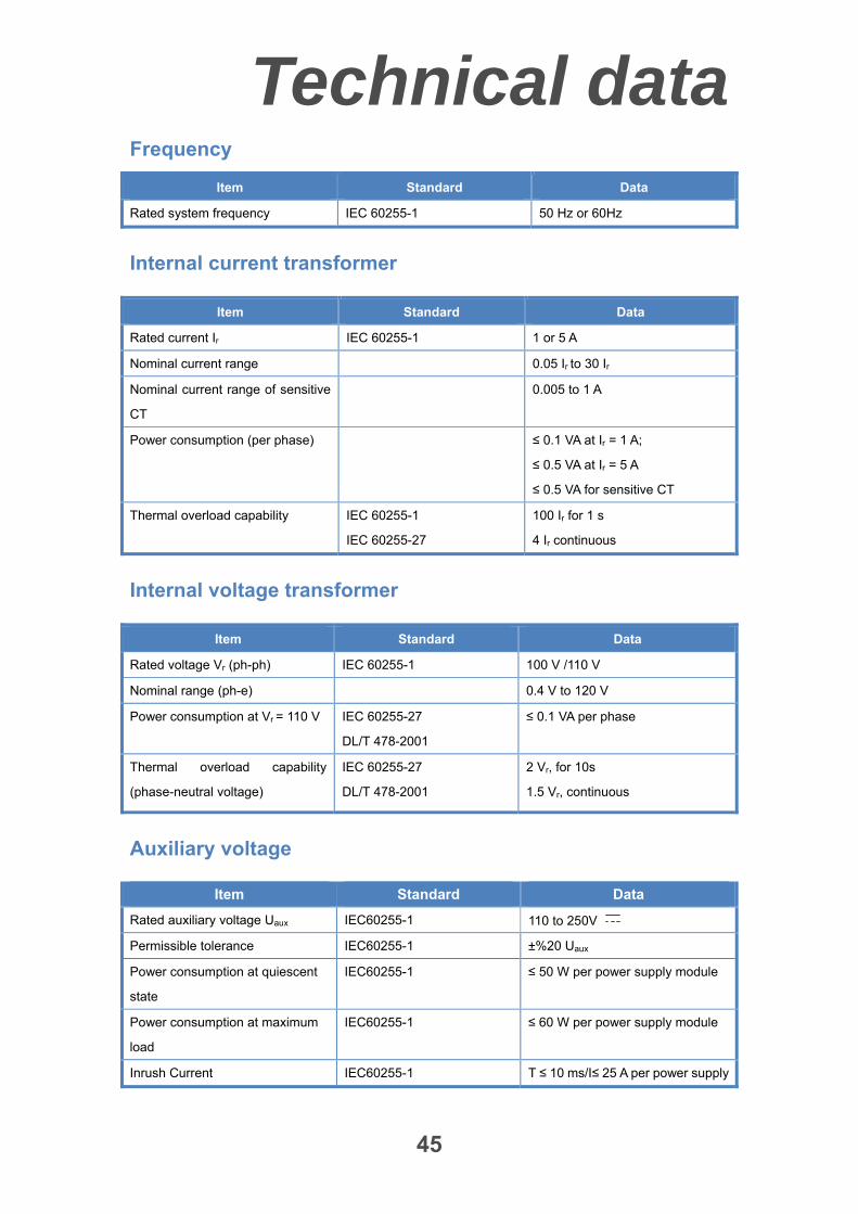
Frequency
Item Standard Data
Rated system frequency IEC 60255-1 50 Hz or 60Hz
Internal current transformer
Item Standard Data
Rated current Ir IEC 60255-1 1 or 5 A
Nominal current range 0.05 Ir to 30 Ir
Nominal current range of sensitive
CT
0.005 to 1 A
Power consumption (per phase) ≤ 0.1 VA at Ir = 1 A;
≤ 0.5 VA at Ir = 5 A
≤ 0.5 VA for sensitive CT
Thermal overload capability IEC 60255-1
IEC 60255-27
100 Ir for 1 s
4 Ir continuous
Internal voltage transformer
Item Standard Data
Rated voltage Vr (ph-ph) IEC 60255-1 100 V /110 V
Nominal range (ph-e) 0.4 V to 120 V
Power consumption at Vr = 110 V IEC 60255-27
DL/T 478-2001
≤ 0.1 VA per phase
Thermal overload capability
(phase-neutral voltage)
IEC 60255-27
DL/T 478-2001
2 Vr, for 10s
1.5 Vr, continuous
Auxiliary voltage
Item Standard Data
Rated auxiliary voltage Uaux IEC60255-1 110 to 250V
Permissible tolerance IEC60255-1 ±%20 Uaux
Power consumption at quiescent
state
IEC60255-1 ≤ 50 W per power supply module
Power consumption at maximum
load
IEC60255-1 ≤ 60 W per power supply module
Inrush Current IEC60255-1 T ≤ 10 ms/I≤ 25 A per power supply
Technical data
46
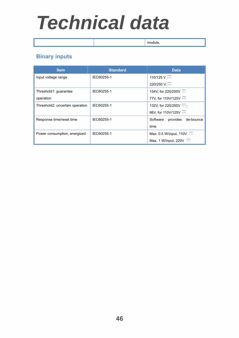
module,
Binary inputs
Item Standard Data
Input voltage range IEC60255-1 110/125 V
220/250 V
Threshold1: guarantee
operation
IEC60255-1 154V, for 220/250V
77V, for 110V/125V
Threshold2: uncertain operation IEC60255-1 132V, for 220/250V ;
66V, for 110V/125V
Response time/reset time IEC60255-1 Software provides de-bounce
time
Power consumption, energized IEC60255-1 Max. 0.5 W/input, 110V
Max. 1 W/input, 220V
Technical Data
47
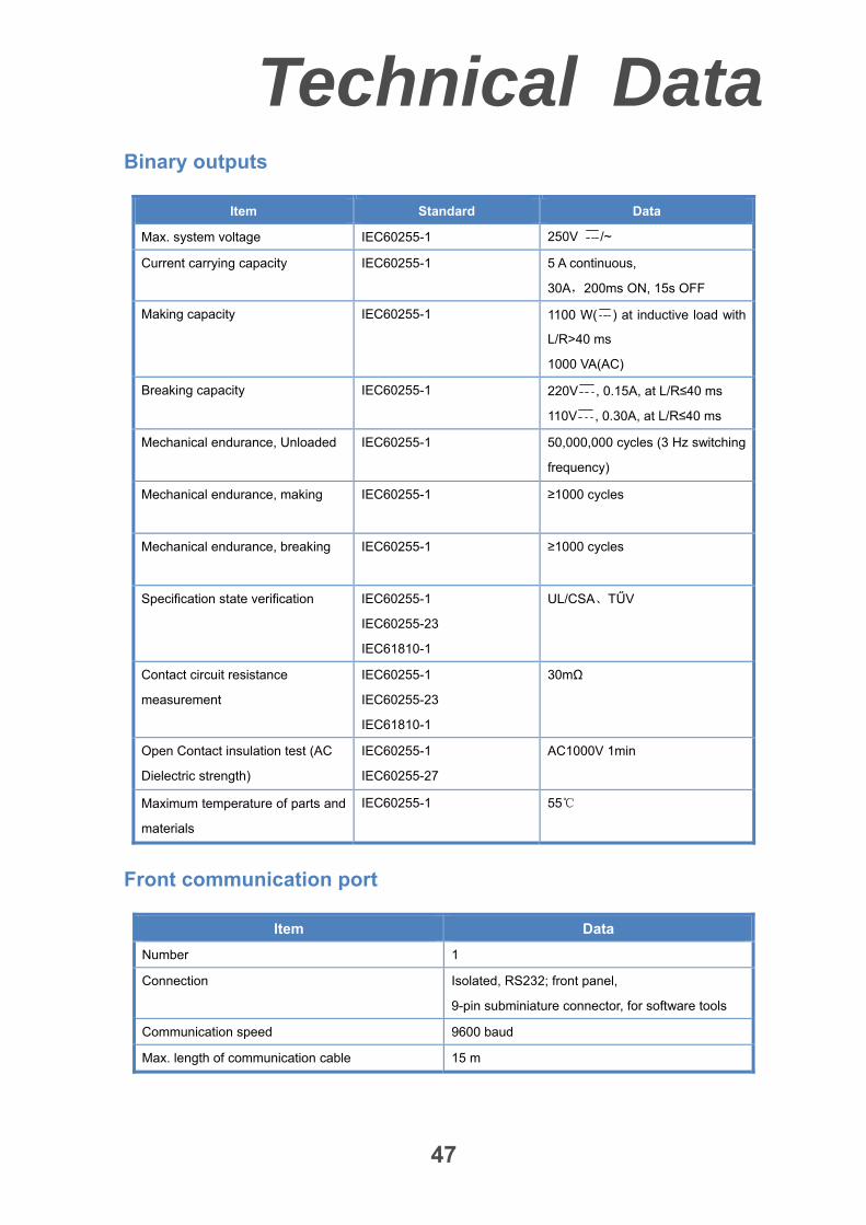
Binary outputs
Item Standard Data
Max. system voltage IEC60255-1 250V /~
Current carrying capacity IEC60255-1 5 A continuous,
30A,200ms ON, 15s OFF
Making capacity IEC60255-1 1100 W( ) at inductive load with
L/R>40 ms
1000 VA(AC)
Breaking capacity IEC60255-1 220V , 0.15A, at L/R≤40 ms
110V , 0.30A, at L/R≤40 ms
Mechanical endurance, Unloaded IEC60255-1 50,000,000 cycles (3 Hz switching
frequency)
Mechanical endurance, making IEC60255-1 ≥1000 cycles
Mechanical endurance, breaking IEC60255-1 ≥1000 cycles
Specification state verification IEC60255-1
IEC60255-23
IEC61810-1
UL/CSA、TŰV
Contact circuit resistance
measurement
IEC60255-1
IEC60255-23
IEC61810-1
30mΩ
Open Contact insulation test (AC
Dielectric strength)
IEC60255-1
IEC60255-27
AC1000V 1min
Maximum temperature of parts and
materials
IEC60255-1 55
Front communication port
Item Data
Number 1
Connection Isolated, RS232; front panel,
9-pin subminiature connector, for software tools
Communication speed 9600 baud
Max. length of communication cable 15 m
Technical Data
48
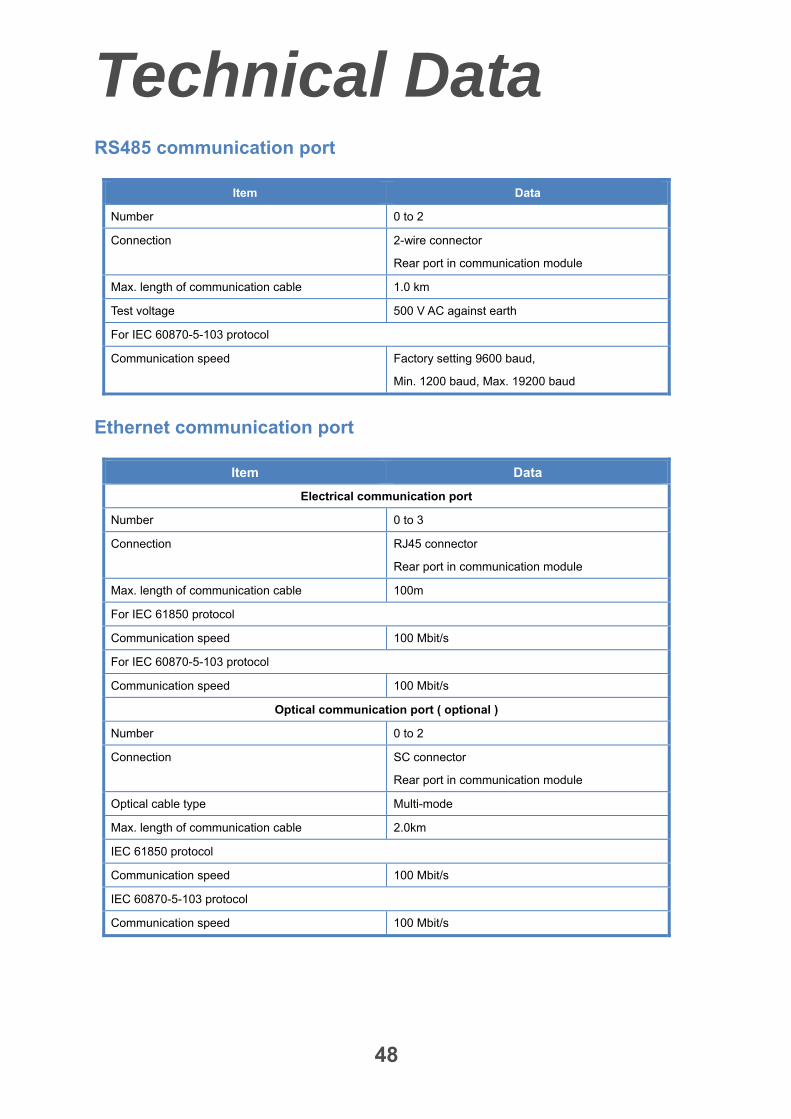
RS485 communication port
Item Data
Number 0 to 2
Connection 2-wire connector
Rear port in communication module
Max. length of communication cable 1.0 km
Test voltage 500 V AC against earth
For IEC 60870-5-103 protocol
Communication speed Factory setting 9600 baud,
Min. 1200 baud, Max. 19200 baud
Ethernet communication port
Item Data
Electrical communication port
Number 0 to 3
Connection RJ45 connector
Rear port in communication module
Max. length of communication cable 100m
For IEC 61850 protocol
Communication speed 100 Mbit/s
For IEC 60870-5-103 protocol
Communication speed 100 Mbit/s
Optical communication port ( optional )
Number 0 to 2
Connection SC connector
Rear port in communication module
Optical cable type Multi-mode
Max. length of communication cable 2.0km
IEC 61850 protocol
Communication speed 100 Mbit/s
IEC 60870-5-103 protocol
Communication speed 100 Mbit/s
Technical Data
49
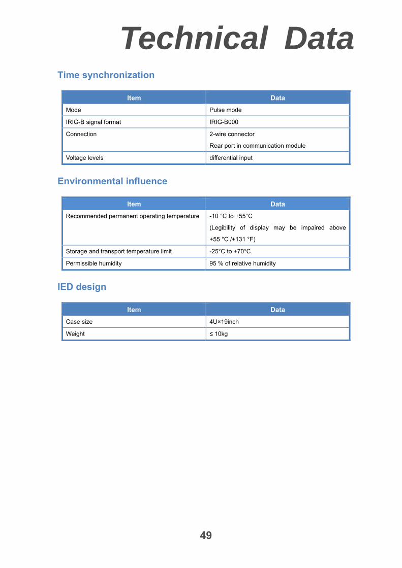
Time synchronization
Item Data
Mode Pulse mode
IRIG-B signal format IRIG-B000
Connection 2-wire connector
Rear port in communication module
Voltage levels differential input
Environmental influence
Item Data
Recommended permanent operating temperature -10 °C to +55°C
(Legibility of display may be impaired above
+55 °C /+131 °F)
Storage and transport temperature limit -25°C to +70°C
Permissible humidity 95 % of relative humidity
IED design
Item Data
Case size 4U×19inch
Weight ≤ 10kg
Technical Data
50
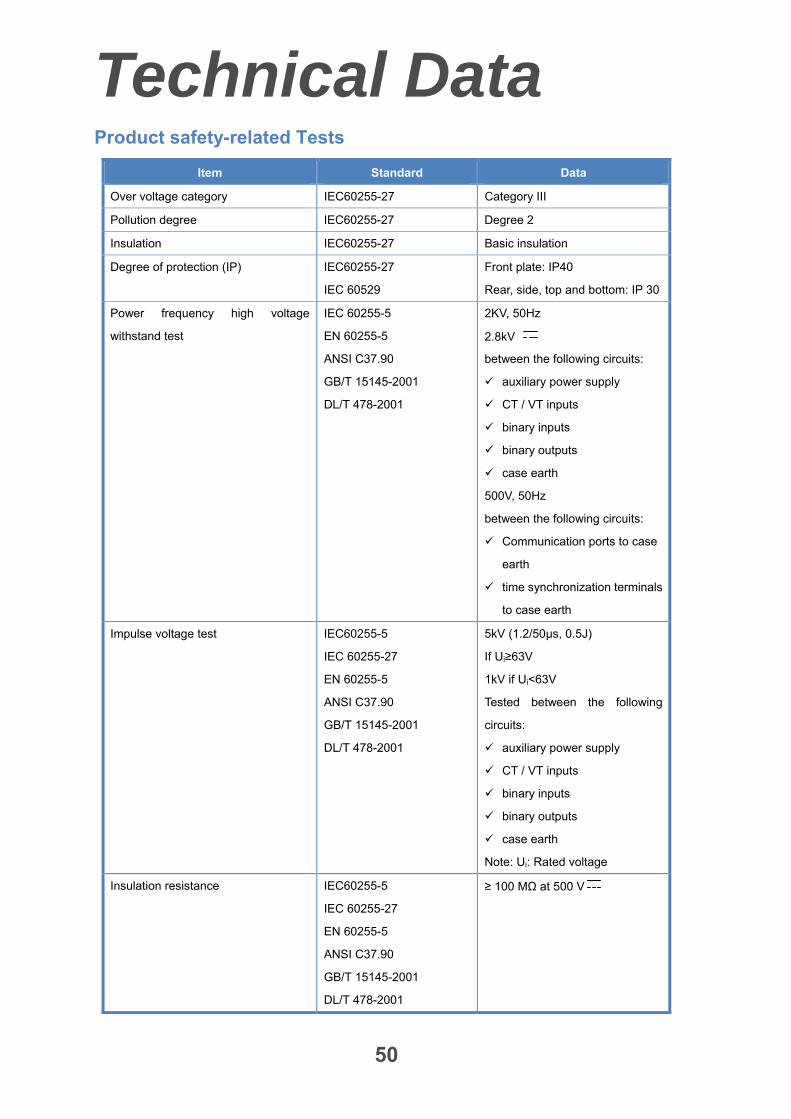
Product safety-related Tests
Item Standard Data
Over voltage category IEC60255-27 Category III
Pollution degree IEC60255-27 Degree 2
Insulation IEC60255-27 Basic insulation
Degree of protection (IP) IEC60255-27
IEC 60529
Front plate: IP40
Rear, side, top and bottom: IP 30
Power frequency high voltage
withstand test
IEC 60255-5
EN 60255-5
ANSI C37.90
GB/T 15145-2001
DL/T 478-2001
2KV, 50Hz
2.8kV
between the following circuits:
auxiliary power supply
CT / VT inputs
binary inputs
binary outputs
case earth
500V, 50Hz
between the following circuits:
Communication ports to case
earth
time synchronization terminals
to case earth
Impulse voltage test IEC60255-5
IEC 60255-27
EN 60255-5
ANSI C37.90
GB/T 15145-2001
DL/T 478-2001
5kV (1.2/50μs, 0.5J)
If Ui≥63V
1kV if Ui<63V
Tested between the following
circuits:
auxiliary power supply
CT / VT inputs
binary inputs
binary outputs
case earth
Note: Ui: Rated voltage
Insulation resistance IEC60255-5
IEC 60255-27
EN 60255-5
ANSI C37.90
GB/T 15145-2001
DL/T 478-2001
≥ 100 MΩ at 500 V
Technical Data
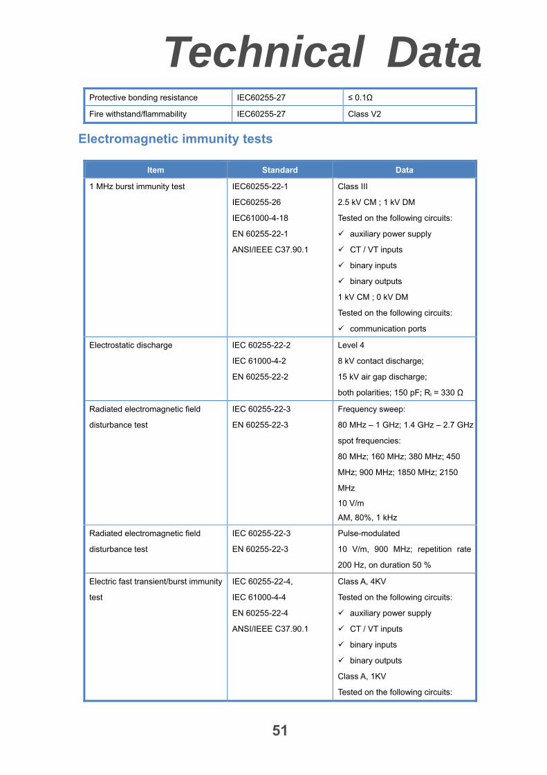
51
Protective bonding resistance IEC60255-27 ≤ 0.1Ω
Fire withstand/flammability IEC60255-27 Class V2
Electromagnetic immunity tests
Item Standard Data
1 MHz burst immunity test IEC60255-22-1
IEC60255-26
IEC61000-4-18
EN 60255-22-1
ANSI/IEEE C37.90.1
Class III
2.5 kV CM ; 1 kV DM
Tested on the following circuits:
auxiliary power supply
CT / VT inputs
binary inputs
binary outputs
1 kV CM ; 0 kV DM
Tested on the following circuits:
communication ports
Electrostatic discharge IEC 60255-22-2
IEC 61000-4-2
EN 60255-22-2
Level 4
8 kV contact discharge;
15 kV air gap discharge;
both polarities; 150 pF; Ri = 330 Ω
Radiated electromagnetic field
disturbance test
IEC 60255-22-3
EN 60255-22-3
Frequency sweep:
80 MHz – 1 GHz; 1.4 GHz – 2.7 GHz
spot frequencies:
80 MHz; 160 MHz; 380 MHz; 450
MHz; 900 MHz; 1850 MHz; 2150
MHz
10 V/m
AM, 80%, 1 kHz
Radiated electromagnetic field
disturbance test
IEC 60255-22-3
EN 60255-22-3
Pulse-modulated
10 V/m, 900 MHz; repetition rate
200 Hz, on duration 50 %
Electric fast transient/burst immunity
test
IEC 60255-22-4,
IEC 61000-4-4
EN 60255-22-4
ANSI/IEEE C37.90.1
Class A, 4KV
Tested on the following circuits:
auxiliary power supply
CT / VT inputs
binary inputs
binary outputs
Class A, 1KV
Tested on the following circuits:
Technical Data
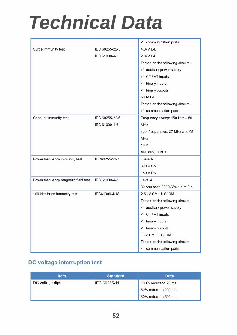
52
communication ports
Surge immunity test IEC 60255-22-5
IEC 61000-4-5
4.0kV L-E
2.0kV L-L
Tested on the following circuits:
auxiliary power supply
CT / VT inputs
binary inputs
binary outputs
500V L-E
Tested on the following circuits:
communication ports
Conduct immunity test IEC 60255-22-6
IEC 61000-4-6
Frequency sweep: 150 kHz – 80
MHz
spot frequencies: 27 MHz and 68
MHz
10 V
AM, 80%, 1 kHz
Power frequency immunity test IEC60255-22-7 Class A
300 V CM
150 V DM
Power frequency magnetic field test IEC 61000-4-8 Level 4
30 A/m cont. / 300 A/m 1 s to 3 s
100 kHz burst immunity test IEC61000-4-18 2.5 kV CM ; 1 kV DM
Tested on the following circuits:
auxiliary power supply
CT / VT inputs
binary inputs
binary outputs
1 kV CM ; 0 kV DM
Tested on the following circuits:
communication ports
DC voltage interruption test
Item Standard Data
DC voltage dips IEC 60255-11 100% reduction 20 ms
60% reduction 200 ms
30% reduction 500 ms
Technical Data
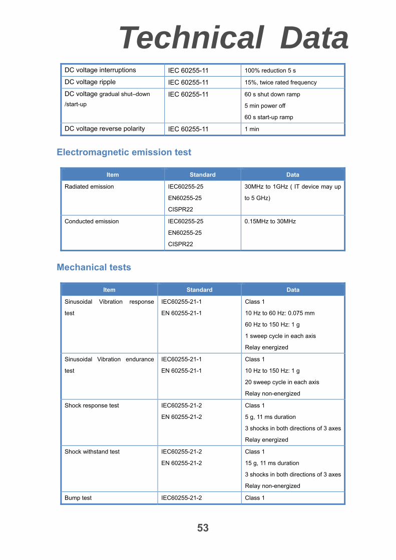
53
DC voltage interruptions IEC 60255-11 100% reduction 5 s
DC voltage ripple IEC 60255-11 15%, twice rated frequency
DC voltage gradual shut–down
/start-up
IEC 60255-11 60 s shut down ramp
5 min power off
60 s start-up ramp
DC voltage reverse polarity IEC 60255-11 1 min
Electromagnetic emission test
Item Standard Data
Radiated emission IEC60255-25
EN60255-25
CISPR22
30MHz to 1GHz ( IT device may up
to 5 GHz)
Conducted emission IEC60255-25
EN60255-25
CISPR22
0.15MHz to 30MHz
Mechanical tests
Item Standard Data
Sinusoidal Vibration response
test
IEC60255-21-1
EN 60255-21-1
Class 1
10 Hz to 60 Hz: 0.075 mm
60 Hz to 150 Hz: 1 g
1 sweep cycle in each axis
Relay energized
Sinusoidal Vibration endurance
test
IEC60255-21-1
EN 60255-21-1
Class 1
10 Hz to 150 Hz: 1 g
20 sweep cycle in each axis
Relay non-energized
Shock response test IEC60255-21-2
EN 60255-21-2
Class 1
5 g, 11 ms duration
3 shocks in both directions of 3 axes
Relay energized
Shock withstand test IEC60255-21-2
EN 60255-21-2
Class 1
15 g, 11 ms duration
3 shocks in both directions of 3 axes
Relay non-energized
Bump test IEC60255-21-2 Class 1
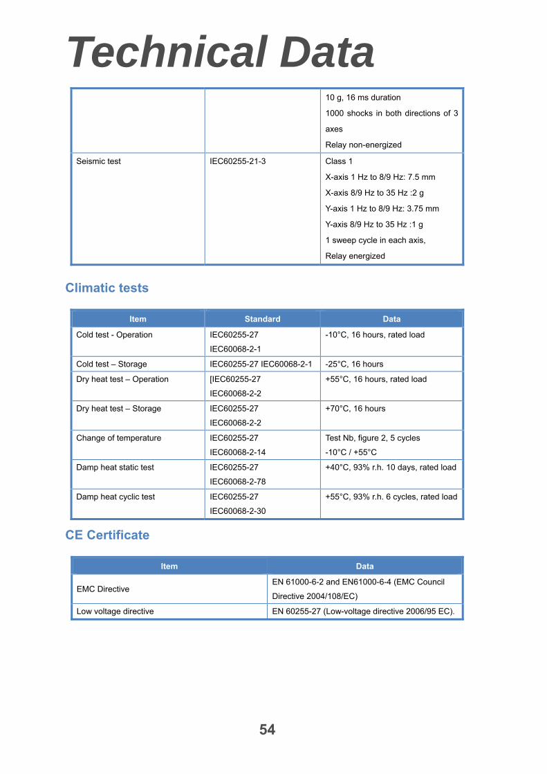
Technical Data
54
10 g, 16 ms duration
1000 shocks in both directions of 3
axes
Relay non-energized
Seismic test IEC60255-21-3 Class 1
X-axis 1 Hz to 8/9 Hz: 7.5 mm
X-axis 8/9 Hz to 35 Hz :2 g
Y-axis 1 Hz to 8/9 Hz: 3.75 mm
Y-axis 8/9 Hz to 35 Hz :1 g
1 sweep cycle in each axis,
Relay energized
Climatic tests
Item Standard Data
Cold test - Operation IEC60255-27
IEC60068-2-1
-10°C, 16 hours, rated load
Cold test – Storage IEC60255-27 IEC60068-2-1 -25°C, 16 hours
Dry heat test – Operation [IEC60255-27
IEC60068-2-2
+55°C, 16 hours, rated load
Dry heat test – Storage IEC60255-27
IEC60068-2-2
+70°C, 16 hours
Change of temperature IEC60255-27
IEC60068-2-14
Test Nb, figure 2, 5 cycles
-10°C / +55°C
Damp heat static test IEC60255-27
IEC60068-2-78
+40°C, 93% r.h. 10 days, rated load
Damp heat cyclic test IEC60255-27
IEC60068-2-30
+55°C, 93% r.h. 6 cycles, rated load
CE Certificate
Item Data
EMC Directive EN 61000-6-2 and EN61000-6-4 (EMC Council
Directive 2004/108/EC)
Low voltage directive EN 60255-27 (Low-voltage directive 2006/95 EC).
Technical Data
55
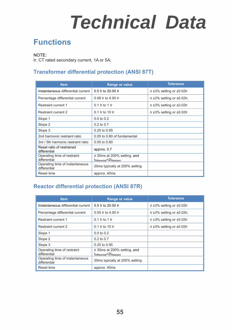
Functions
NOTE: Ir: CT rated secondary current, 1A or 5A;
Transformer differential protection (ANSI 87T)
Item Range or value Tolerance
Instantaneous differential current 0.5 Ir to 20.00 Ir ≤ ±3% setting or ±0.02Ir
Percentage differential current 0.08 Ir to 4.00 Ir ≤ ±3% setting or ±0.02Ir,
Restraint current 1 0.1 Ir to 1 Ir ≤ ±3% setting or ±0.02Ir
Restraint current 2 0.1 Ir to 10 Ir ≤ ±3% setting or ±0.02Ir
Slope 1 0.0 to 0.2
Slope 2 0.2 to 0.7
Slope 3 0.25 to 0.95
2nd harmonic restraint ratio 0.05 to 0.80 of fundamental
3rd / 5th harmonic restraint ratio 0.05 to 0.80
Reset ratio of restrained differential
approx. 0.7
Operating time of restraint differential
≤ 30ms at 200% setting, and IDifferential>2IRestraint
Operating time of instantaneous differential
20ms typically at 200% setting
Reset time approx. 40ms
Reactor differential protection (ANSI 87R)
Item Range or value Tolerance
Instantaneous differential current 0.5 Ir to 20.00 Ir ≤ ±3% setting or ±0.02Ir
Percentage differential current 0.05 Ir to 4.00 Ir ≤ ±3% setting or ±0.02Ir,
Restraint current 1 0.1 Ir to 1 Ir ≤ ±3% setting or ±0.02Ir
Restraint current 2 0.1 Ir to 10 Ir ≤ ±3% setting or ±0.02Ir
Slope 1 0.0 to 0.2
Slope 2 0.2 to 0.7
Slope 3 0.25 to 0.95
Operating time of restraint differential
≤ 30ms at 200% setting, and IDifferential>2IRestraint
Operating time of instantaneous differential
20ms typically at 200% setting
Reset time approx. 40ms
Technical Data
56
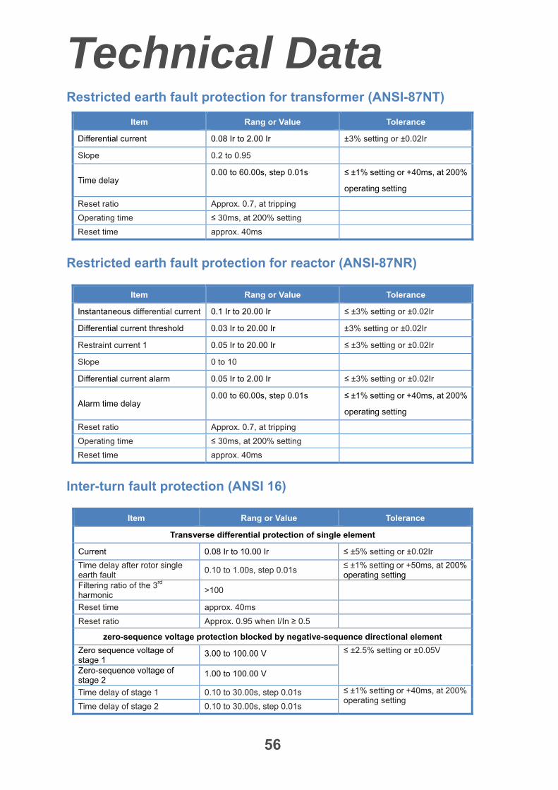
Restricted earth fault protection for transformer (ANSI-87NT)
Item Rang or Value Tolerance
Differential current 0.08 Ir to 2.00 Ir ±3% setting or ±0.02Ir
Slope 0.2 to 0.95
Time delay 0.00 to 60.00s, step 0.01s ≤ ±1% setting or +40ms, at 200%
operating setting
Reset ratio Approx. 0.7, at tripping
Operating time ≤ 30ms, at 200% setting
Reset time approx. 40ms
Restricted earth fault protection for reactor (ANSI-87NR)
Item Rang or Value Tolerance
Instantaneous differential current 0.1 Ir to 20.00 Ir ≤ ±3% setting or ±0.02Ir
Differential current threshold 0.03 Ir to 20.00 Ir ±3% setting or ±0.02Ir
Restraint current 1 0.05 Ir to 20.00 Ir ≤ ±3% setting or ±0.02Ir
Slope 0 to 10
Differential current alarm 0.05 Ir to 2.00 Ir ≤ ±3% setting or ±0.02Ir
Alarm time delay 0.00 to 60.00s, step 0.01s ≤ ±1% setting or +40ms, at 200%
operating setting
Reset ratio Approx. 0.7, at tripping
Operating time ≤ 30ms, at 200% setting
Reset time approx. 40ms
Inter-turn fault protection (ANSI 16)
Item Rang or Value Tolerance
Transverse differential protection of single element
Current 0.08 Ir to 10.00 Ir ≤ ±5% setting or ±0.02Ir
Time delay after rotor single earth fault
0.10 to 1.00s, step 0.01s ≤ ±1% setting or +50ms, at 200% operating setting
Filtering ratio of the 3rd harmonic
>100
Reset time approx. 40ms
Reset ratio Approx. 0.95 when I/In ≥ 0.5
zero-sequence voltage protection blocked by negative-sequence directional element
Zero sequence voltage of stage 1
3.00 to 100.00 V ≤ ±2.5% setting or ±0.05V
Zero-sequence voltage of stage 2
1.00 to 100.00 V
Time delay of stage 1 0.10 to 30.00s, step 0.01s ≤ ±1% setting or +40ms, at 200% operating setting
Time delay of stage 2 0.10 to 30.00s, step 0.01s
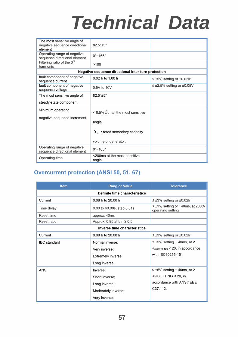
Technical Data
57
The most sensitive angle of negative sequence directional element
82.5°±5°
Operating range of negative sequence directional element
0°~165°
Filtering ratio of the 3rd harmonic
>100
Negative-sequence directional inter-turn protection
fault component of negative sequence current
0.02 Ir to 1.00 Ir ≤ ±5% setting or ±0.02Ir
fault component of negative sequence voltage
0.5V to 10V ≤ ±2.5% setting or ±0.05V
The most sensitive angle of
steady-state component
82.5°±5°
Minimum operating
negative-sequence increment
< 0.5% nS at the most sensitive
angle.
nS : rated secondary capacity
volume of generator.
Operating range of negative sequence directional element
0°~165°
Operating time <200ms at the most sensitive angle.
Overcurrent protection (ANSI 50, 51, 67)
Item Rang or Value Tolerance
Definite time characteristics
Current 0.08 Ir to 20.00 Ir ≤ ±3% setting or ±0.02Ir
Time delay 0.00 to 60.00s, step 0.01s ≤ ±1% setting or +40ms, at 200% operating setting
Reset time approx. 40ms
Reset ratio Approx. 0.95 at I/In ≥ 0.5
Inverse time characteristics
Current 0.08 Ir to 20.00 Ir ≤ ±3% setting or ±0.02Ir
IEC standard Normal inverse;
Very inverse;
Extremely inverse;
Long inverse
≤ ±5% setting + 40ms, at 2
<I/ISETTING < 20, in accordance
with IEC60255-151
ANSI Inverse;
Short inverse;
Long inverse;
Moderately inverse;
Very inverse;
≤ ±5% setting + 40ms, at 2
<I/ISETTING < 20, in
accordance with ANSI/IEEE
C37.112,
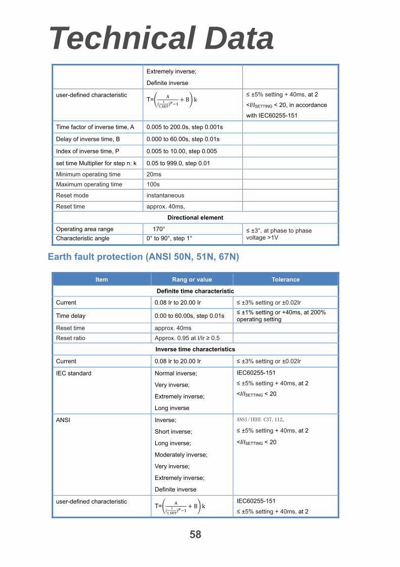
Technical Data
58
Extremely inverse;
Definite inverse
user-defined characteristic T=
_
B k ≤ ±5% setting + 40ms, at 2
<I/ISETTING < 20, in accordance
with IEC60255-151
Time factor of inverse time, A 0.005 to 200.0s, step 0.001s
Delay of inverse time, B 0.000 to 60.00s, step 0.01s
Index of inverse time, P 0.005 to 10.00, step 0.005
set time Multiplier for step n: k 0.05 to 999.0, step 0.01
Minimum operating time 20ms
Maximum operating time 100s
Reset mode instantaneous
Reset time approx. 40ms,
Directional element
Operating area range 170° ≤ ±3°, at phase to phase voltage >1V Characteristic angle 0° to 90°, step 1°
Earth fault protection (ANSI 50N, 51N, 67N)
Item Rang or value Tolerance
Definite time characteristic
Current 0.08 Ir to 20.00 Ir ≤ ±3% setting or ±0.02Ir
Time delay 0.00 to 60.00s, step 0.01s ≤ ±1% setting or +40ms, at 200% operating setting
Reset time approx. 40ms
Reset ratio Approx. 0.95 at I/Ir ≥ 0.5
Inverse time characteristics
Current 0.08 Ir to 20.00 Ir ≤ ±3% setting or ±0.02Ir
IEC standard Normal inverse;
Very inverse;
Extremely inverse;
Long inverse
IEC60255-151
≤ ±5% setting + 40ms, at 2
<I/ISETTING < 20
ANSI Inverse;
Short inverse;
Long inverse;
Moderately inverse;
Very inverse;
Extremely inverse;
Definite inverse
ANSI/IEEE C37.112,
≤ ±5% setting + 40ms, at 2
<I/ISETTING < 20
user-defined characteristic T=
_
B k IEC60255-151
≤ ±5% setting + 40ms, at 2
Technical Data
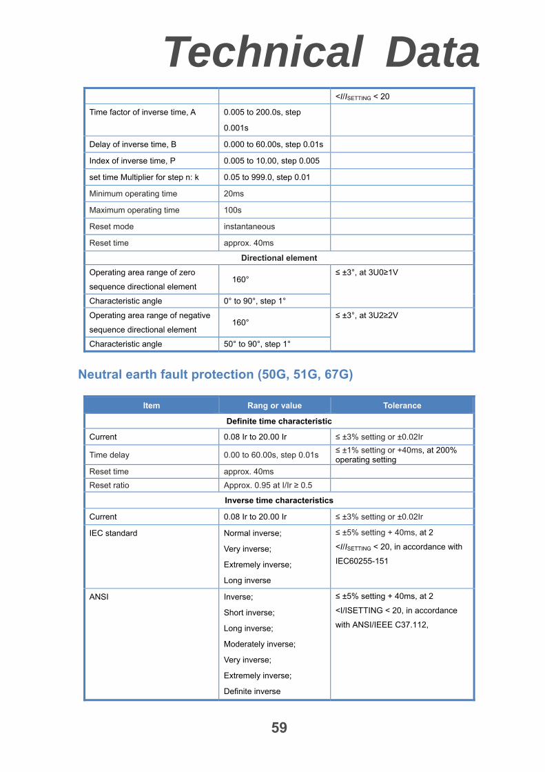
59
<I/ISETTING < 20
Time factor of inverse time, A 0.005 to 200.0s, step
0.001s
Delay of inverse time, B 0.000 to 60.00s, step 0.01s
Index of inverse time, P 0.005 to 10.00, step 0.005
set time Multiplier for step n: k 0.05 to 999.0, step 0.01
Minimum operating time 20ms
Maximum operating time 100s
Reset mode instantaneous
Reset time approx. 40ms
Directional element
Operating area range of zero
sequence directional element 160°
≤ ±3°, at 3U0≥1V
Characteristic angle 0° to 90°, step 1°
Operating area range of negative
sequence directional element 160°
≤ ±3°, at 3U2≥2V
Characteristic angle 50° to 90°, step 1°
Neutral earth fault protection (50G, 51G, 67G)
Item Rang or value Tolerance
Definite time characteristic
Current 0.08 Ir to 20.00 Ir ≤ ±3% setting or ±0.02Ir
Time delay 0.00 to 60.00s, step 0.01s ≤ ±1% setting or +40ms, at 200% operating setting
Reset time approx. 40ms
Reset ratio Approx. 0.95 at I/Ir ≥ 0.5
Inverse time characteristics
Current 0.08 Ir to 20.00 Ir ≤ ±3% setting or ±0.02Ir
IEC standard Normal inverse;
Very inverse;
Extremely inverse;
Long inverse
≤ ±5% setting + 40ms, at 2
<I/ISETTING < 20, in accordance with
IEC60255-151
ANSI Inverse;
Short inverse;
Long inverse;
Moderately inverse;
Very inverse;
Extremely inverse;
Definite inverse
≤ ±5% setting + 40ms, at 2
<I/ISETTING < 20, in accordance
with ANSI/IEEE C37.112,
Technical Data
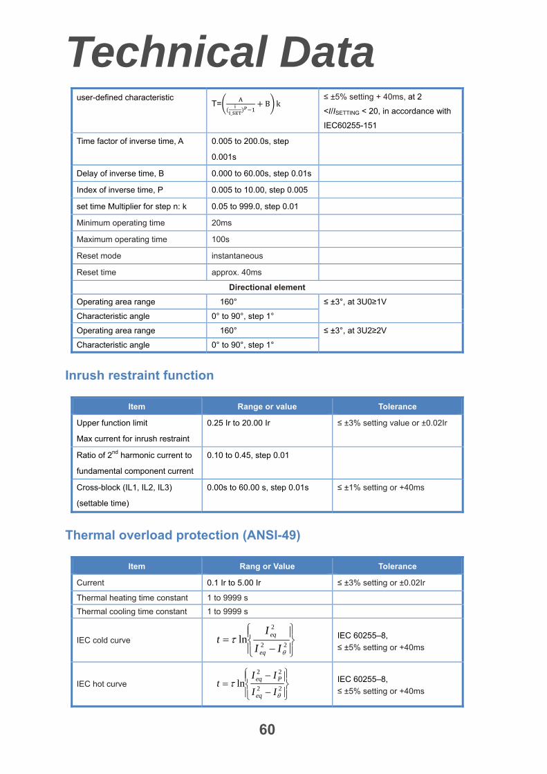
60
user-defined characteristic T=
_
B k ≤ ±5% setting + 40ms, at 2
<I/ISETTING < 20, in accordance with
IEC60255-151
Time factor of inverse time, A 0.005 to 200.0s, step
0.001s
Delay of inverse time, B 0.000 to 60.00s, step 0.01s
Index of inverse time, P 0.005 to 10.00, step 0.005
set time Multiplier for step n: k 0.05 to 999.0, step 0.01
Minimum operating time 20ms
Maximum operating time 100s
Reset mode instantaneous
Reset time approx. 40ms
Directional element
Operating area range 160° ≤ ±3°, at 3U0≥1V
Characteristic angle 0° to 90°, step 1°
Operating area range 160° ≤ ±3°, at 3U2≥2V
Characteristic angle 0° to 90°, step 1°
Inrush restraint function
Item Range or value Tolerance
Upper function limit
Max current for inrush restraint
0.25 Ir to 20.00 Ir ≤ ±3% setting value or ±0.02Ir
Ratio of 2nd harmonic current to
fundamental component current
0.10 to 0.45, step 0.01
Cross-block (IL1, IL2, IL3)
(settable time)
0.00s to 60.00 s, step 0.01s ≤ ±1% setting or +40ms
Thermal overload protection (ANSI-49)
Item Rang or Value Tolerance
Current 0.1 Ir to 5.00 Ir ≤ ±3% setting or ±0.02Ir
Thermal heating time constant 1 to 9999 s
Thermal cooling time constant 1 to 9999 s
IEC cold curve
22
2
ln
II
It
eq
eq IEC 60255–8,
≤ ±5% setting or +40ms
IEC hot curve
22
22
ln
II
IIt
eq
Peq
IEC 60255–8,
≤ ±5% setting or +40ms
Technical Data
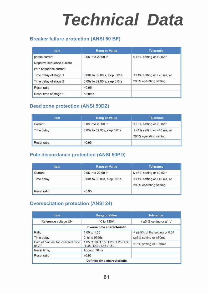
61
Breaker failure protection (ANSI 50 BF)
Item Rang or Value Tolerance
phase current
Negative sequence current
zero sequence current
0.08 Ir to 20.00 Ir ≤ ±3% setting or ±0.02Ir
Time delay of stage 1 0.00s to 32.00 s, step 0.01s ≤ ±1% setting or +25 ms, at
200% operating setting Time delay of stage 2 0.00s to 32.00 s, step 0.01s
Reset ratio >0.95
Reset time of stage 1 < 20ms
Dead zone protection (ANSI 50DZ)
Item Rang or Value Tolerance
Current 0.08 Ir to 20.00 Ir ≤ ±3% setting or ±0.02Ir
Time delay 0.00s to 32.00s, step 0.01s ≤ ±1% setting or +40 ms, at
200% operating setting
Reset ratio >0.95
Pole discordance protection (ANSI 50PD)
Item Rang or Value Tolerance
Current 0.08 Ir to 20.00 Ir ≤ ±3% setting or ±0.02Ir
Time delay 0.00s to 60.00s, step 0.01s ≤ ±1% setting or +40 ms, at
200% operating setting
Reset ratio >0.95
Overexcitation protection (ANSI 24)
Item Rang or Value Tolerance
Reference voltage UN 40 to 130V, ≤ ±3 % setting or ±1 V
Inverse time characteristic
Ratio: 1.00 to 1.50 ≤ ±2.5% of the setting or 0.01
Time delay 0.1s to 9999s ≤±5% setting or ±70ms
Pair of Values for characteristic of V/f
1.05 /1.10 /1.15 /1.20 /1.25 /1.30 /1.35 /1.40 /1.45 /1.50
≤±5% setting or ± 70ms
Reset time, Approx. 70ms
Reset ratio ≥0.96
Definite time characteristic
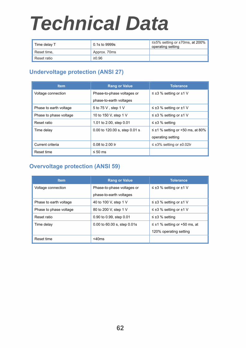
Technical Data
62
Time delay T 0.1s to 9999s ≤±5% setting or ±70ms, at 200% operating setting
Reset time, Approx. 70ms
Reset ratio ≥0.96
Undervoltage protection (ANSI 27)
Item Rang or Value Tolerance
Voltage connection Phase-to-phase voltages or
phase-to-earth voltages
≤ ±3 % setting or ±1 V
Phase to earth voltage 5 to 75 V , step 1 V ≤ ±3 % setting or ±1 V
Phase to phase voltage 10 to 150 V, step 1 V ≤ ±3 % setting or ±1 V
Reset ratio 1.01 to 2.00, step 0.01 ≤ ±3 % setting
Time delay 0.00 to 120.00 s, step 0.01 s ≤ ±1 % setting or +50 ms, at 80%
operating setting
Current criteria 0.08 to 2.00 Ir ≤ ±3% setting or ±0.02Ir
Reset time ≤ 50 ms
Overvoltage protection (ANSI 59)
Item Rang or Value Tolerance
Voltage connection Phase-to-phase voltages or
phase-to-earth voltages
≤ ±3 % setting or ±1 V
Phase to earth voltage 40 to 100 V, step 1 V ≤ ±3 % setting or ±1 V
Phase to phase voltage 80 to 200 V, step 1 V ≤ ±3 % setting or ±1 V
Reset ratio 0.90 to 0.99, step 0.01 ≤ ±3 % setting
Time delay 0.00 to 60.00 s, step 0.01s ≤ ±1 % setting or +50 ms, at
120% operating setting
Reset time <40ms
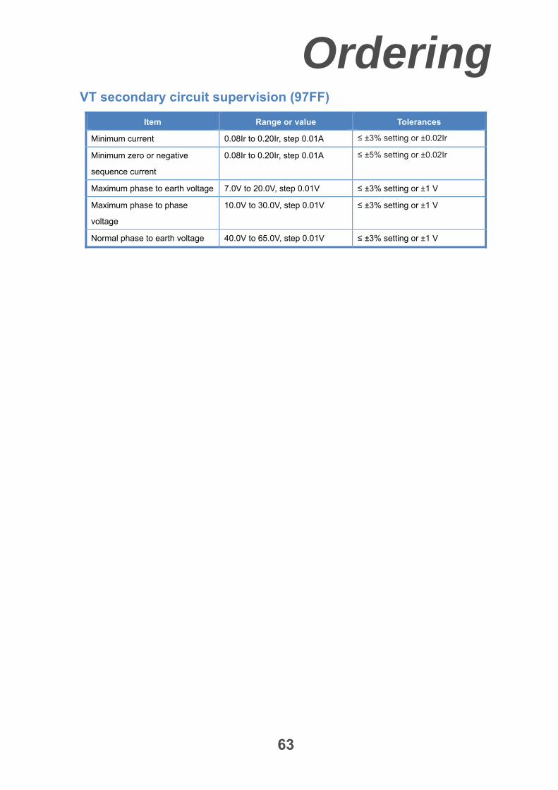
Ordering
63
VT secondary circuit supervision (97FF)
Item Range or value Tolerances
Minimum current 0.08Ir to 0.20Ir, step 0.01A ≤ ±3% setting or ±0.02Ir
Minimum zero or negative
sequence current
0.08Ir to 0.20Ir, step 0.01A ≤ ±5% setting or ±0.02Ir
Maximum phase to earth voltage 7.0V to 20.0V, step 0.01V ≤ ±3% setting or ±1 V
Maximum phase to phase
voltage
10.0V to 30.0V, step 0.01V ≤ ±3% setting or ±1 V
Normal phase to earth voltage 40.0V to 65.0V, step 0.01V ≤ ±3% setting or ±1 V
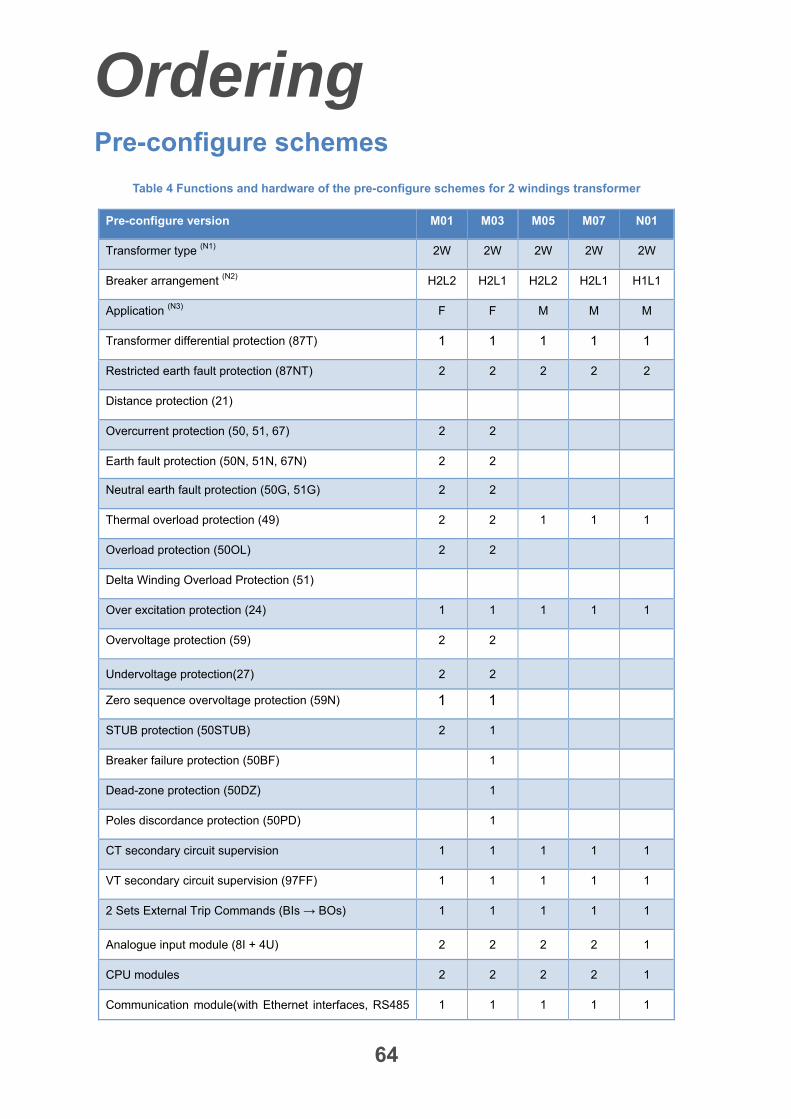
Ordering
64
Pre-configure schemes
Table 4 Functions and hardware of the pre-configure schemes for 2 windings transformer
Pre-configure version M01 M03 M05 M07 N01
Transformer type (N1) 2W 2W 2W 2W 2W
Breaker arrangement (N2) H2L2 H2L1 H2L2 H2L1 H1L1
Application (N3) F F M M M
Transformer differential protection (87T) 1 1 1 1 1
Restricted earth fault protection (87NT) 2 2 2 2 2
Distance protection (21)
Overcurrent protection (50, 51, 67) 2 2
Earth fault protection (50N, 51N, 67N) 2 2
Neutral earth fault protection (50G, 51G) 2 2
Thermal overload protection (49) 2 2 1 1 1
Overload protection (50OL) 2 2
Delta Winding Overload Protection (51)
Over excitation protection (24) 1 1 1 1 1
Overvoltage protection (59) 2 2
Undervoltage protection(27) 2 2
Zero sequence overvoltage protection (59N) 1 1
STUB protection (50STUB) 2 1
Breaker failure protection (50BF) 1
Dead-zone protection (50DZ) 1
Poles discordance protection (50PD) 1
CT secondary circuit supervision 1 1 1 1 1
VT secondary circuit supervision (97FF) 1 1 1 1 1
2 Sets External Trip Commands (BIs → BOs) 1 1 1 1 1
Analogue input module (8I + 4U) 2 2 2 2 1
CPU modules 2 2 2 2 1
Communication module(with Ethernet interfaces, RS485 1 1 1 1 1
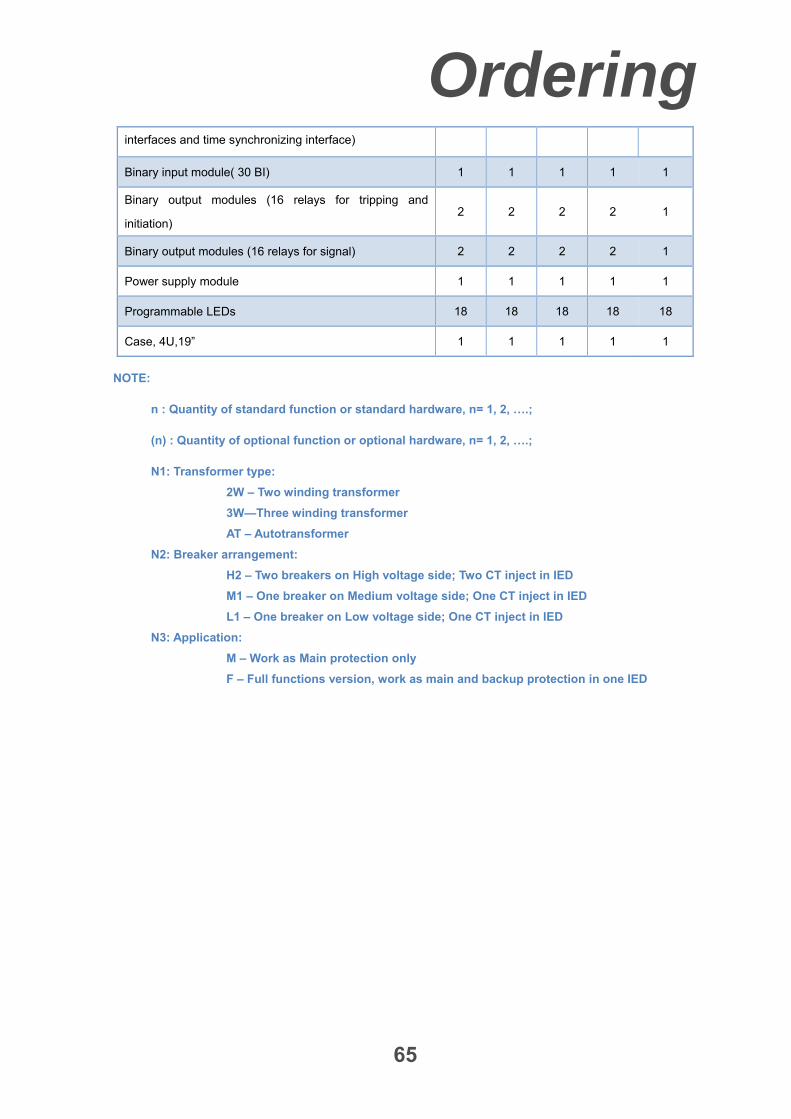
Ordering
65
interfaces and time synchronizing interface)
Binary input module( 30 BI) 1 1 1 1 1
Binary output modules (16 relays for tripping and
initiation) 2 2 2 2 1
Binary output modules (16 relays for signal) 2 2 2 2 1
Power supply module 1 1 1 1 1
Programmable LEDs 18 18 18 18 18
Case, 4U,19” 1 1 1 1 1
NOTE:
n : Quantity of standard function or standard hardware, n= 1, 2, ….;
(n) : Quantity of optional function or optional hardware, n= 1, 2, ….;
N1: Transformer type:
2W – Two winding transformer
3W—Three winding transformer
AT – Autotransformer
N2: Breaker arrangement:
H2 – Two breakers on High voltage side; Two CT inject in IED
M1 – One breaker on Medium voltage side; One CT inject in IED
L1 – One breaker on Low voltage side; One CT inject in IED
N3: Application:
M – Work as Main protection only
F – Full functions version, work as main and backup protection in one IED
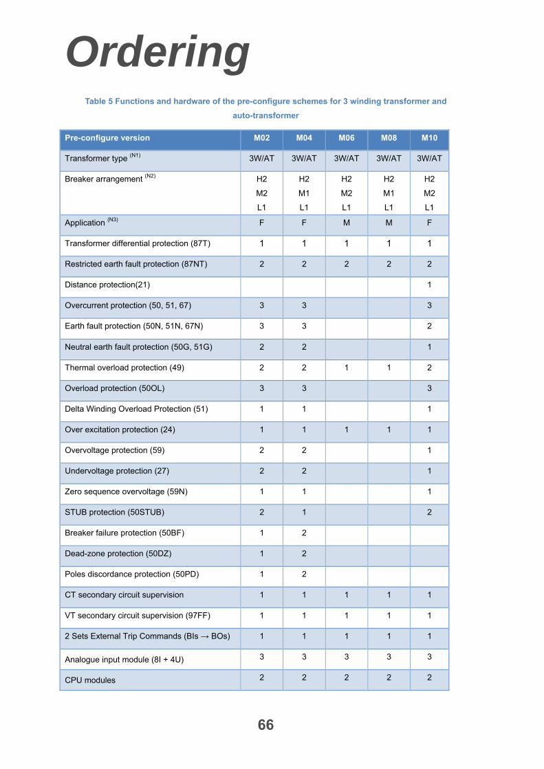
Ordering
66
Table 5 Functions and hardware of the pre-configure schemes for 3 winding transformer and
auto-transformer
Pre-configure version M02 M04 M06 M08 M10
Transformer type (N1) 3W/AT 3W/AT 3W/AT 3W/AT 3W/AT
Breaker arrangement (N2) H2
M2
L1
H2
M1
L1
H2
M2
L1
H2
M1
L1
H2
M2
L1
Application (N3) F F M M F
Transformer differential protection (87T) 1 1 1 1 1
Restricted earth fault protection (87NT) 2 2 2 2 2
Distance protection(21) 1
Overcurrent protection (50, 51, 67) 3 3 3
Earth fault protection (50N, 51N, 67N) 3 3 2
Neutral earth fault protection (50G, 51G) 2 2 1
Thermal overload protection (49) 2 2 1 1 2
Overload protection (50OL) 3 3 3
Delta Winding Overload Protection (51) 1 1 1
Over excitation protection (24) 1 1 1 1 1
Overvoltage protection (59) 2 2 1
Undervoltage protection (27) 2 2 1
Zero sequence overvoltage (59N) 1 1 1
STUB protection (50STUB) 2 1 2
Breaker failure protection (50BF) 1 2
Dead-zone protection (50DZ) 1 2
Poles discordance protection (50PD) 1 2
CT secondary circuit supervision 1 1 1 1 1
VT secondary circuit supervision (97FF) 1 1 1 1 1
2 Sets External Trip Commands (BIs → BOs) 1 1 1 1 1
Analogue input module (8I + 4U) 3 3 3 3 3
CPU modules 2 2 2 2 2
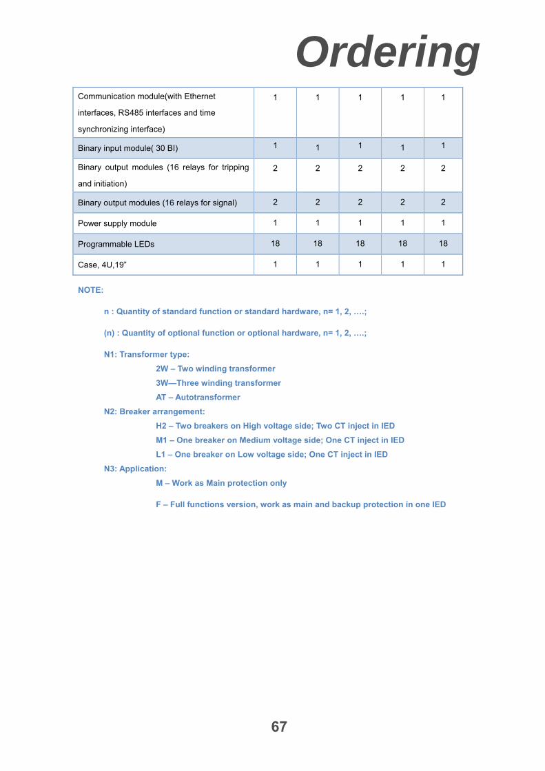
Ordering
67
Communication module(with Ethernet
interfaces, RS485 interfaces and time
synchronizing interface)
1 1 1 1 1
Binary input module( 30 BI) 1 1 1 1 1
Binary output modules (16 relays for tripping
and initiation)
2 2 2 2 2
Binary output modules (16 relays for signal) 2 2 2 2 2
Power supply module 1 1 1 1 1
Programmable LEDs 18 18 18 18 18
Case, 4U,19” 1 1 1 1 1
NOTE:
n : Quantity of standard function or standard hardware, n= 1, 2, ….;
(n) : Quantity of optional function or optional hardware, n= 1, 2, ….;
N1: Transformer type:
2W – Two winding transformer
3W—Three winding transformer
AT – Autotransformer
N2: Breaker arrangement:
H2 – Two breakers on High voltage side; Two CT inject in IED
M1 – One breaker on Medium voltage side; One CT inject in IED
L1 – One breaker on Low voltage side; One CT inject in IED
N3: Application:
M – Work as Main protection only
F – Full functions version, work as main and backup protection in one IED
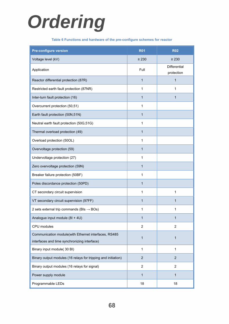
Ordering
68
Table 6 Functions and hardware of the pre-configure schemes for reactor
Pre-configure version R01 R02
Voltage level (kV) ≥ 230 ≥ 230
Application Full Differential
protection
Reactor differential protection (87R) 1 1
Restricted earth fault protection (87NR) 1 1
Inter-turn fault protection (16) 1 1
Overcurrent protection (50,51) 1
Earth fault protection (50N,51N) 1
Neutral earth fault protection (50G,51G) 1
Thermal overload protection (49) 1
Overload protection (50OL) 1
Overvoltage protection (59) 1
Undervoltage protection (27) 1
Zero overvoltage protection (59N) 1
Breaker failure protection (50BF) 1
Poles discordance protection (50PD) 1
CT secondary circuit supervision 1 1
VT secondary circuit supervision (97FF) 1 1
2 sets external trip commands (BIs → BOs) 1 1
Analogue input module (8I + 4U) 1 1
CPU modules 2 2
Communication module(with Ethernet interfaces, RS485
interfaces and time synchronizing interface) 1 1
Binary input module( 30 BI) 1 1
Binary output modules (16 relays for tripping and initiation) 2 2
Binary output modules (16 relays for signal) 2 2
Power supply module 1 1
Programmable LEDs 18 18
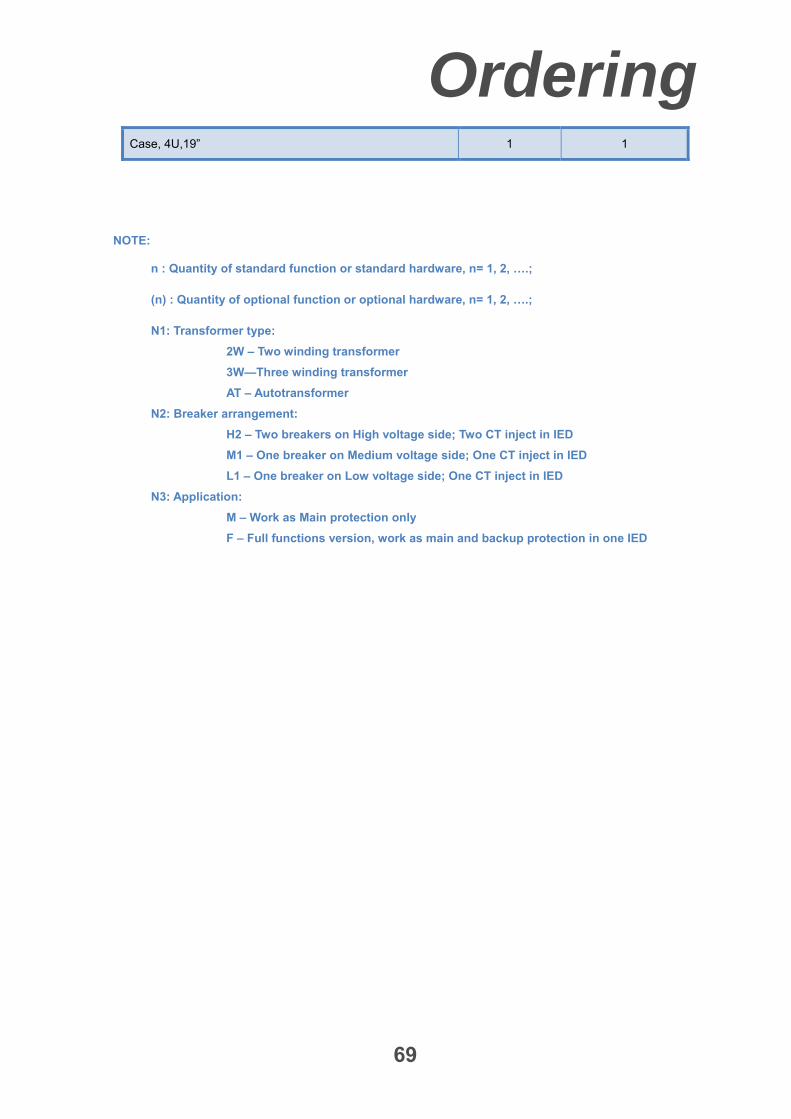
Ordering
69
Case, 4U,19” 1 1
NOTE:
n : Quantity of standard function or standard hardware, n= 1, 2, ….;
(n) : Quantity of optional function or optional hardware, n= 1, 2, ….;
N1: Transformer type:
2W – Two winding transformer
3W—Three winding transformer
AT – Autotransformer
N2: Breaker arrangement:
H2 – Two breakers on High voltage side; Two CT inject in IED
M1 – One breaker on Medium voltage side; One CT inject in IED
L1 – One breaker on Low voltage side; One CT inject in IED
N3: Application:
M – Work as Main protection only
F – Full functions version, work as main and backup protection in one IED
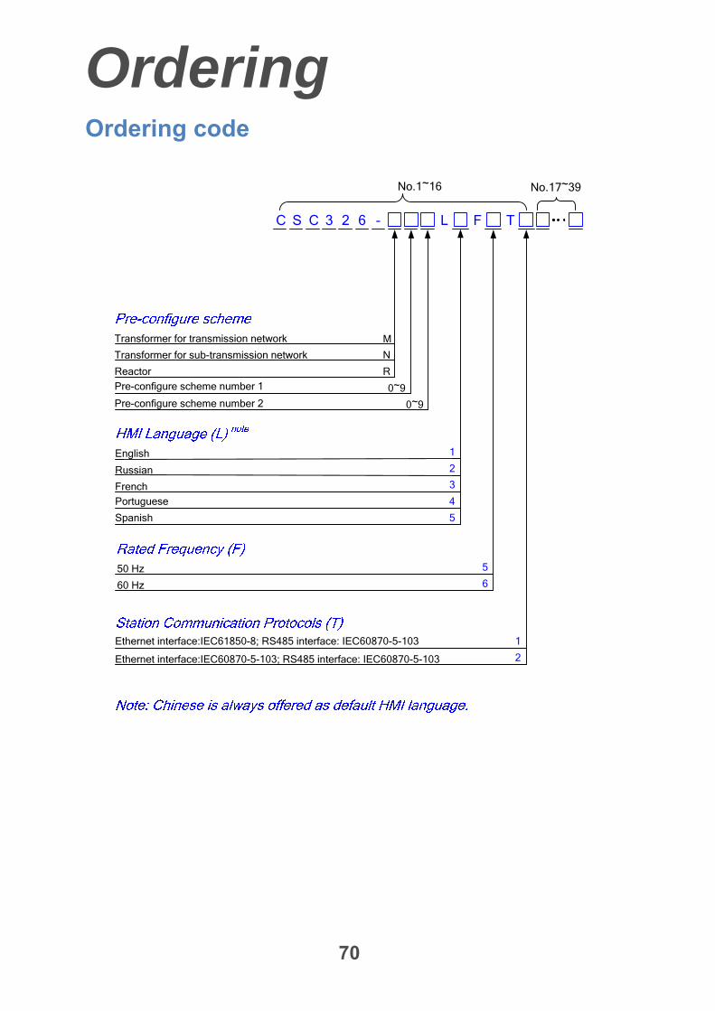
Ordering
70
Ordering code
C
M
0~9
0~9
No.1~16 No.17~39
S 3 2 -C 6
Ethernet interface:IEC61850-8; RS485 interface: IEC60870-5-103
English
French
Russian
Spanish
Portuguese
1
2
3
4
5
50 Hz 5
660 Hz
Ethernet interface:IEC60870-5-103; RS485 interface: IEC60870-5-103
FL T
1
2
Transformer for transmission network
Pre-configure scheme number 1
Pre-configure scheme number 2
Transformer for sub-transmission network N
Reactor R
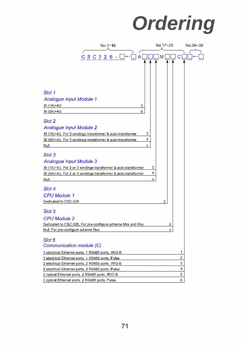
Ordering
71
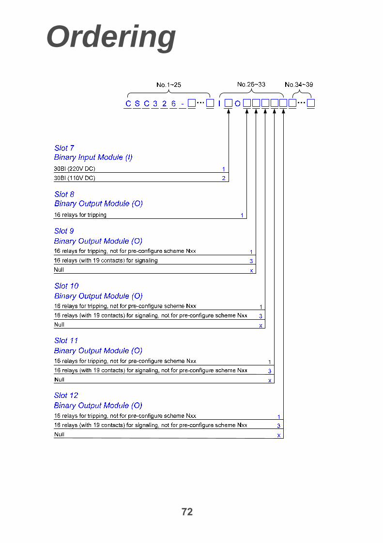
Ordering
72
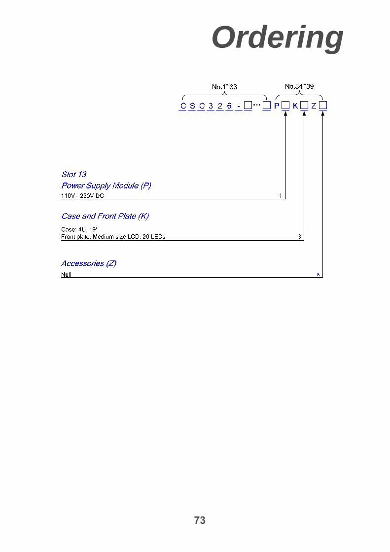
Ordering
73