Embed Size (px)
Citation preview
8/3/2019 CSANR2010-001.Ch09
http://slidepdf.com/reader/full/csanr2010-001ch09 1/24
CSANR Research Report 2010 – 001 Climate Friendly Farming
Ch. 9 Compressed Biomethane Page 1
Purification Technologies for Biogas Generated by
Anaerobic Digestion
Q. Zhao, E. Leonhardt, C. MacConnell, C. Frear and S. Chen
Background Biogas is produced in many different environments, including in landfills, sewagesludge and during anaerobic degradation of organic material. Biogas is comprised of methane (CH4, about 45-75% by volume), carbon dioxide (CO2, 25-55%), and othercompounds including hydrogen sulfide (H2S, present in concentrations from severalhundred to a couple of thousand parts per million), water, and other trace gascompounds. Methane is a powerful greenhouse gas if emitted into the atmosphere,but can also represent a valuable renewable energy source, with the potential toreduce GHG emissions when it is collected and substituted for fossil fuels.
Biogas can be used directly to generate power, but the large volume of CO2 reducesthe heating value of the gas, increasing compression and transportation costs andlimiting economic feasibility to uses that occur at the point of production.Purification allows for a wider variety of uses, either for heat and electricity, or forvehicle fuels. For use as a fuel, purification to remove carbon dioxide (CO2) andhydrogen sulfide (H2S) is required, because H2S corrodes vital mechanicalcomponents within engine generator sets and vehicle engines if it is not removed.
Purified biogas provides reductions in GHG emissions as well as several otherenvironmental benefits when used as a vehicle fuel. Biogas emits less nitrogenoxide, hydrocarbon and carbon monoxide than gasoline or diesel, and enginesfueled by purified biogas are quieter than diesel engines. Refueling with biogas
presents fewer environmental risks than refueling with gasoline or diesel, because it can be done at small units located at an owner’s home or business, minimizing thepotential impacts if leaks or spills occur. Potential negatives include the high cost ($3-6/GJ) to upgrade the biogas, reduced driving range for vehicles dependent onspecialty fuel, and less cargo space due to biogas storage.
Feasible biogas purification technologies exist for large-scale sewage and biowastedigesters, and the technologies for upgrading biogas, compressing, storing anddispensing biomethane are well developed. If cost-effective methods for upgradingbiogas could be developed for the farm-scale, biogas purification could providedairy farmers with revenue to complement (or replace) electrical power sales. This
is especially critical in the Pacific Northwest, where low power rates have preventedcost competitive power from farm-scale anaerobic-digesters, limiting total dairy-derived power.
Engine conversion to accommodate biogas also represents a potential barrier, but because biogas has the same properties as natural gas, it can be easily used byvehicles which are configured for natural gas. Worldwide, there are about 10,000biogas driven cars and buses, plus an additional 3.8 million natural gas fuelled
8/3/2019 CSANR2010-001.Ch09
http://slidepdf.com/reader/full/csanr2010-001ch09 2/24
CSANR Research Report 2010 – 001 Climate Friendly Farming
Ch. 9 Compressed Biomethane Page 2
vehicles (representing 0.5% of the world vehicle stock), mainly in Argentina, Brazil,Pakistan, Italy, India and the U.S. (ENGVA, 2004).
To help develop appropriate biogas purification technologies for farm-scaleanaerobic digesters, Washington State University evaluated various methods forremoving acidic impurities, and developed and tested absorption towertechnologies for application to a farm-scale anaerobic digester. In addition, WesternWashington University has begun the process of building a full-scale pilot system.This pilot system will purify biogas from Vander Haak Dairy (Lynden, Washington),and sell it to Airporter Shuttle/Belair Charters for use by buses running along theInterstate 5 “Green” corridor from the Seatac airport south of Seattle to Ferndale,north of Bellingham. This is a new project for the diary industry, fuel users, and thecommunity, as there is currently only one operational dairy-derived biomethane fortransportation facility in North America, at the Hilarides Dairy in Lindsay, California,which began operation in the summer of 2009.
Evaluation of Existing Biogas Purification Technologies (Washington State
University)
A review of existing technical solutions for scrubbing CO2 and/or H2S was carriedout to identify the most promising options for application to farm scale anaerobicdigesters. Existing technologies are summarized below with their major strengthsand weaknesses.
Water and Polyethylene Glycol Scrubbing
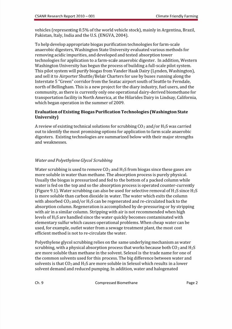
Water scrubbing is used to remove CO2 and H2S from biogas since these gases aremore soluble in water than methane. The absorption process is purely physical.Usually the biogas is pressurized and fed to the bottom of a packed column whilewater is fed on the top and so the absorption process is operated counter-currently(Figure 9.1). Water scrubbing can also be used for selective removal of H2S since H2Sis more soluble than carbon dioxide in water. The water which exits the columnwith absorbed CO2 and/or H2S can be regenerated and re-circulated back to theabsorption column. Regeneration is accomplished by de-pressuring or by strippingwith air in a similar column. Stripping with air is not recommended when highlevels of H2S are handled since the water quickly becomes contaminated withelementary sulfur which causes operational problems. When cheap water can beused, for example, outlet water from a sewage treatment plant, the most cost efficient method is not to re-circulate the water.
Polyethylene glycol scrubbing relies on the same underlying mechanism as waterscrubbing, with a physical absorption process that works because both CO2 and H2Sare more soluble than methane in the solvent. Selexol is the trade name for one of the common solvents used for this process. The big difference between water andsolvents is that CO2 and H2S are more soluble in Selexol which results in a lowersolvent demand and reduced pumping. In addition, water and halogenated
8/3/2019 CSANR2010-001.Ch09
http://slidepdf.com/reader/full/csanr2010-001ch09 3/24
CSANR Research Report 2010 – 001 Climate Friendly Farming
Ch. 9 Compressed Biomethane Page 3
hydrocarbons (contaminants in biogas from landfills) are removed when scrubbingbiogas with Selexol. Selexol scrubbing is always designed with recirculation. Due toformation of elementary sulfur stripping the Selexol solvent is normally done withsteam or inert gas rather than with air. Removing H2S beforehand is an alternative.
Figure 9.1: Flow chart of water scrubbing technology
The advantages of scrubbing are no special chemicals required (except relatively
inexpensive glycol) and removal of both CO2 and H2S. The disadvantages of water
scrubbing are that it requires a lot of water even with regeneration, as well as limitations
on H2S removal, because the CO2 decreases pH of the solution and corrosion to the
equipment caused by H2S. According to De Hullu et al. (2008), the cost of the water
scrubbing method is 0.13 €/Nm3
biogas.
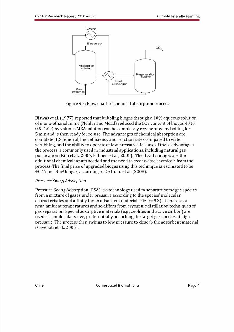
Chemical Absorption
Chemical absorption involves formation of reversible chemical bonds between the solute
and the solvent. Regeneration of the solvent, therefore, involves breaking of these bonds
and correspondingly, a relatively high energy input (Figure 9.2). Chemical solvents
generally employ either aqueous solutions of amines (i.e. mono-, di- or tri-ethanolamine)
or aqueous solution of alkaline salts (i.e. sodium, potassium and calcium hydroxides).
8/3/2019 CSANR2010-001.Ch09
http://slidepdf.com/reader/full/csanr2010-001ch09 4/24
CSANR Research Report 2010 – 001 Climate Friendly Farming
Ch. 9 Compressed Biomethane Page 4
Figure 9.2: Flow chart of chemical absorption process
Biswas et al. (1977) reported that bubbling biogas through a 10% aqueous solutionof mono-ethanolamine (Nelder and Mead) reduced the CO2 content of biogas 40 to0.5–1.0% by volume. MEA solution can be completely regenerated by boiling for5 min and is then ready for re-use. The advantages of chemical absorption arecomplete H2S removal, high efficiency and reaction rates compared to waterscrubbing, and the ability to operate at low pressure. Because of these advantages,the process is commonly used in industrial applications, including natural gaspurification (Kim et al., 2004; Palmeri et al., 2008). The disadvantages are theadditional chemical inputs needed and the need to treat waste chemicals from theprocess. The final price of upgraded biogas using this technique is estimated to be€0.17 per Nm3 biogas, according to De Hullu et al. (2008).
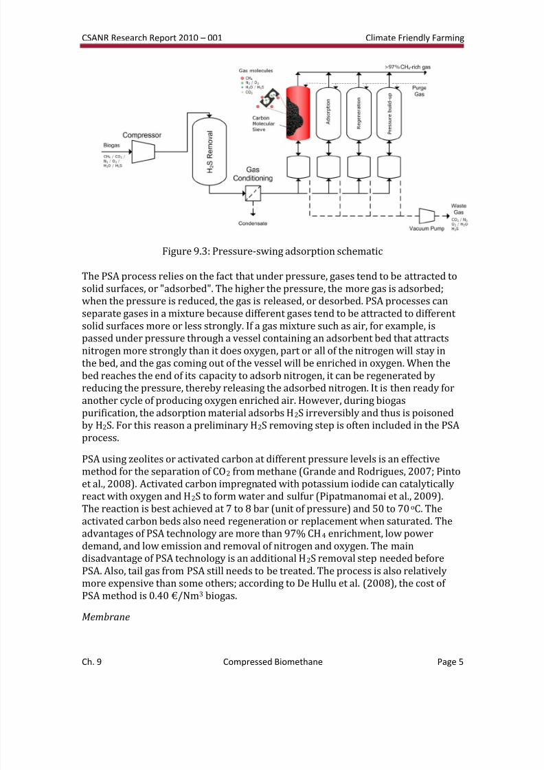
Pressure Swing Adsorption
Pressure Swing Adsorption (PSA) is a technology used to separate some gas speciesfrom a mixture of gases under pressure according to the species' molecularcharacteristics and affinity for an adsorbent material (Figure 9.3). It operates at near-ambient temperatures and so differs from cryogenic distillation techniques of gas separation. Special adsorptive materials (e.g., zeolites and active carbon) areused as a molecular sieve, preferentially adsorbing the target gas species at highpressure. The process then swings to low pressure to desorb the adsorbent material(Cavenati et al., 2005).
8/3/2019 CSANR2010-001.Ch09
http://slidepdf.com/reader/full/csanr2010-001ch09 5/24
CSANR Research Report 2010 – 001 Climate Friendly Farming
Ch. 9 Compressed Biomethane Page 5
Figure 9.3: Pressure-swing adsorption schematic
The PSA process relies on the fact that under pressure, gases tend to be attracted tosolid surfaces, or "adsorbed". The higher the pressure, the more gas is adsorbed;when the pressure is reduced, the gas is released, or desorbed. PSA processes canseparate gases in a mixture because different gases tend to be attracted to different solid surfaces more or less strongly. If a gas mixture such as air, for example, ispassed under pressure through a vessel containing an adsorbent bed that attractsnitrogen more strongly than it does oxygen, part or all of the nitrogen will stay inthe bed, and the gas coming out of the vessel will be enriched in oxygen. When thebed reaches the end of its capacity to adsorb nitrogen, it can be regenerated byreducing the pressure, thereby releasing the adsorbed nitrogen. It is then ready for
another cycle of producing oxygen enriched air. However, during biogaspurification, the adsorption material adsorbs H2S irreversibly and thus is poisonedby H2S. For this reason a preliminary H2S removing step is often included in the PSAprocess.
PSA using zeolites or activated carbon at different pressure levels is an effectivemethod for the separation of CO2 from methane (Grande and Rodrigues, 2007; Pintoet al., 2008). Activated carbon impregnated with potassium iodide can catalyticallyreact with oxygen and H2S to form water and sulfur (Pipatmanomai et al., 2009).The reaction is best achieved at 7 to 8 bar (unit of pressure) and 50 to 70oC. Theactivated carbon beds also need regeneration or replacement when saturated. Theadvantages of PSA technology are more than 97% CH4 enrichment, low powerdemand, and low emission and removal of nitrogen and oxygen. The maindisadvantage of PSA technology is an additional H2S removal step needed beforePSA. Also, tail gas from PSA still needs to be treated. The process is also relativelymore expensive than some others; according to De Hullu et al. (2008), the cost of PSA method is 0.40 €/Nm3 biogas.
Membrane
8/3/2019 CSANR2010-001.Ch09
http://slidepdf.com/reader/full/csanr2010-001ch09 6/24
CSANR Research Report 2010 – 001 Climate Friendly Farming
Ch. 9 Compressed Biomethane Page 6
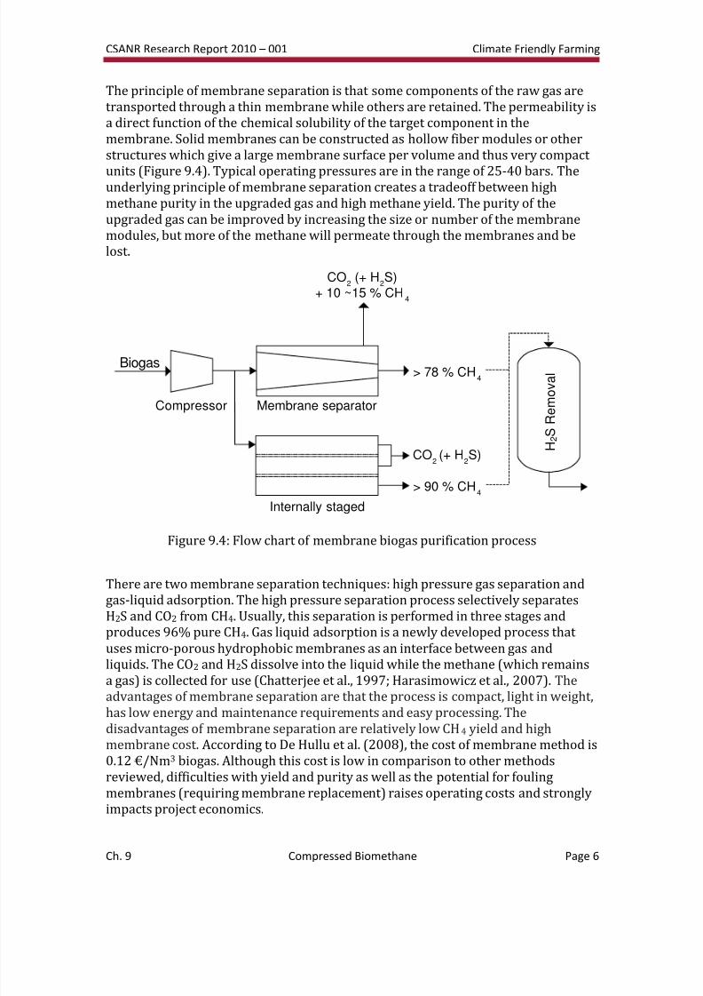
The principle of membrane separation is that some components of the raw gas aretransported through a thin membrane while others are retained. The permeability isa direct function of the chemical solubility of the target component in themembrane. Solid membranes can be constructed as hollow fiber modules or otherstructures which give a large membrane surface per volume and thus very compact
units (Figure 9.4). Typical operating pressures are in the range of 25-40 bars. Theunderlying principle of membrane separation creates a tradeoff between highmethane purity in the upgraded gas and high methane yield. The purity of theupgraded gas can be improved by increasing the size or number of the membranemodules, but more of the methane will permeate through the membranes and belost.
Figure 9.4: Flow chart of membrane biogas purification process
There are two membrane separation techniques: high pressure gas separation andgas-liquid adsorption. The high pressure separation process selectively separatesH2S and CO2 from CH4. Usually, this separation is performed in three stages andproduces 96% pure CH4. Gas liquid adsorption is a newly developed process that uses micro-porous hydrophobic membranes as an interface between gas andliquids. The CO2 and H2S dissolve into the liquid while the methane (which remainsa gas) is collected for use (Chatterjee et al., 1997; Harasimowicz et al., 2007). The
advantages of membrane separation are that the process is compact, light in weight,has low energy and maintenance requirements and easy processing. Thedisadvantages of membrane separation are relatively low CH4 yield and highmembrane cost. According to De Hullu et al. (2008), the cost of membrane method is0.12 €/Nm3 biogas. Although this cost is low in comparison to other methodsreviewed, difficulties with yield and purity as well as the potential for foulingmembranes (requiring membrane replacement) raises operating costs and stronglyimpacts project economics.
H 2 S R e m o v a l
Compressor
Biogas
Membrane separator
Internally staged
> 78 % CH4
CO2
(+ H2S)
+ 10 ~15 % CH4
CO2(+ H
2S)
> 90 % CH4
8/3/2019 CSANR2010-001.Ch09
http://slidepdf.com/reader/full/csanr2010-001ch09 7/24
CSANR Research Report 2010 – 001 Climate Friendly Farming
Ch. 9 Compressed Biomethane Page 7
Bio-filter
Biological processes are widely employed for H2S removal, especially in biogasapplications. Because chemical use is limited, they are often economical andenvironmentally friendly (Duan et al., 2006; van der Zee et al., 2007). The use of chemotropic bacterial species (Thiobacillus genus) to condition biogas is wellestablished. Microalgae cultures have also been examined but the availableliterature is short and cannot help in appropriately evaluating this option. Anothermethodology deploys anaerobic phototrophic bacteria (Cholorobium limicola)capable of oxidizing H2S in the presence of light and CO2. No known commercialapplications at this time use phototrophic bacteria. The following text thereforefocuses on chemotrophic bacteria.
Chemotrophic thiobacteria can purify H2S in both aerobic and anaerobic pathways.Most thiobacteria are autotrophic, consuming CO2 and generating chemical energyfrom the oxidation of reduced inorganic compounds such as H2S. These processescommonly produce SO4
2− and S0 as waste products. On the other hand, somethiobacteria (i.e., Thiobacillus novellus, Thiothrix nivea) can grow eitherheterotrophically or autotrophically, having the capability of using available organicmaterial as carbon source (i.e., glucose, amino acids). Biogas, which contains around30% CO2, is a good source of inorganic carbon, rendering it more suitable forautotrophic bacteria. Under limited oxygen conditions, Thiobacillus bacteria evoke aredox-reaction which produces S0 (Equation 1). Conversely, an excess oxygencondition will lead to SO4
2− generation and, thus, acidification, as shown in equation1.
H2S ↔H+ + HS− (dissociation)
HS−
+ 0.5O2 → S0 + OH−
(1)
HS− + 2O2 → SO42− + H+
Chung et al. (1996) isolated Thiobacillus thioparus from swine wastewater. Thebacteria were immobilized with Caalginate to produce pellet-packing materials for alab-scale biofilter (5-cm diameter, 25-cm working length). Growth was optimum at pH 6–8 under facultative autotrophic and heterotrophic conditions. The biofilterwas operated under air-H2S mixture flow between 36 to 150 L/h containing 5 to100 ppmv of H2S. Removal efficiency was more than 98% at residence times higherthan 28 s. Optimal S-loading was 25 g m−3 h−1. The main product was (i) S0 (72%) at high H2S concentration (60 ppmv), and (ii) sulfate (75%) at low H2S concentration(5 ppmv). No pH fluctuation was observed. The experiments showed notemperature influence on removal efficiency between 20° and 37°C.
Thiobacillus ferroxidans, another potential bacterial species, is an example of achemotrophic aerobe which can oxidize FeSO4 to Fe2(SO4)3. The resultant Fe3+ solutions are capable of dissolving H2S and oxidizing it to S0. This allows S0 separation and permits biological FeSO4 regeneration. These bacteria are acidophilic
8/3/2019 CSANR2010-001.Ch09
http://slidepdf.com/reader/full/csanr2010-001ch09 8/24
CSANR Research Report 2010 – 001 Climate Friendly Farming
Ch. 9 Compressed Biomethane Page 8
and are able to grow at low pH levels (1 to 6). The main biochemical reaction isdetailed in Equation 2.
2FeSO4 + 1/2 O2 + H2SO4 → Fe2(SO4)3 + H2O (pH = 2) (2)
Acidithiobacillus thiooxidans AZ11 has been isolated and incubated from H2S-
enriched soil (Lee et al., 2006). The bacteria can live in a very acidic environment, aslow as pH = 0.2, with high sulfate concentration (74 g/l). A lab-scale biofilter (4.6 cmdiameter, 30 cm working length) was inoculated with these inocula on a crushed,porous ceramic support. The study showed that, at a low flow rate (space velocity =200 h/1) and residence time of 18 s, this species was capable of degrading high H2Sconcentration (2200 ppmv) and S-loading of 670 g/(m3*h). Removal efficiencyranged from 94% to 99.9% and was demonstrated to be dependent on residencetime (the studied range was 6 to 18 s).
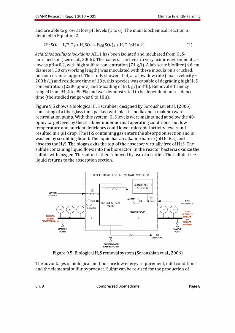
Figure 9.5 shows a biological H2S scrubber designed by Soroushian et al. (2006),consisting of a fiberglass tank packed with plastic media and a makeup water
recirculation pump. With this system, H2S levels were maintained at below the 40-ppmv target level by the scrubber under normal operating conditions, but lowtemperature and nutrient deficiency could lower microbial activity levels andresulted in a pH drop. The H2S containing gas enters the absorption section and iswashed by scrubbing liquid. The liquid has an alkaline nature (pH 8–8.5) andabsorbs the H2S. The biogas exits the top of the absorber virtually free of H2S. Thesulfide containing liquid flows into the bioreactor. In the reactor bacteria oxidize thesulfide with oxygen. The sulfur is then removed by use of a settler. The sulfide-freeliquid returns to the absorption section.
Figure 9.5: Biological H2S removal system (Soroushian et al., 2006)
The advantages of biological methods are low energy requirement, mild conditionsand the elemental sulfur byproduct. Sulfur can be re-used for the production of
8/3/2019 CSANR2010-001.Ch09
http://slidepdf.com/reader/full/csanr2010-001ch09 9/24
CSANR Research Report 2010 – 001 Climate Friendly Farming
Ch. 9 Compressed Biomethane Page 9
sulfuric acid, hydrogen sulfide or agricultural applications (Kim et al., 2002; Vanniniet al., 2008). Biological methods also have some disadvantages: additional nutrientsare required for growing bacteria, and a small amount of O2 and N2 are left intreated biogas. The H2S removal efficiency depends on the activity of bacteria. Bench-marking studies show that the method described above is cost effective up to
40 tons per day.
Cryogenic Separation
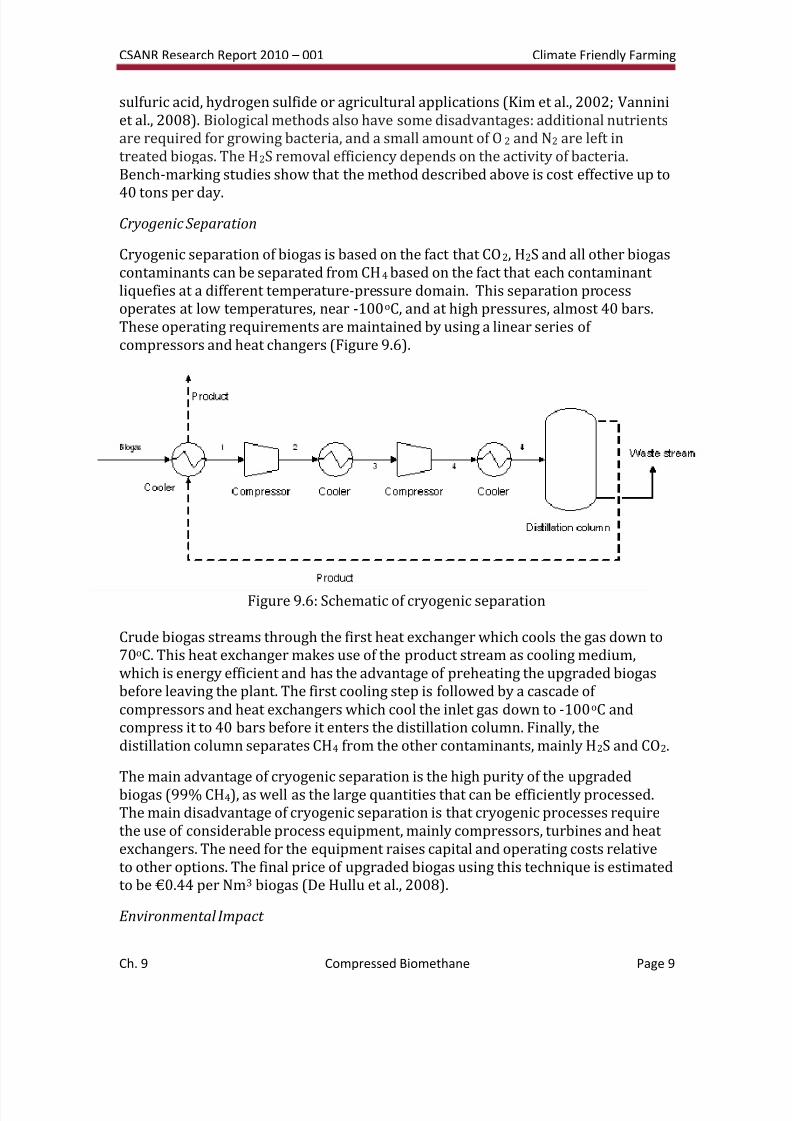
Cryogenic separation of biogas is based on the fact that CO2, H2S and all other biogascontaminants can be separated from CH4 based on the fact that each contaminant liquefies at a different temperature-pressure domain. This separation processoperates at low temperatures, near -100oC, and at high pressures, almost 40 bars.These operating requirements are maintained by using a linear series of compressors and heat changers (Figure 9.6).
Figure 9.6: Schematic of cryogenic separation
Crude biogas streams through the first heat exchanger which cools the gas down to70oC. This heat exchanger makes use of the product stream as cooling medium,which is energy efficient and has the advantage of preheating the upgraded biogasbefore leaving the plant. The first cooling step is followed by a cascade of compressors and heat exchangers which cool the inlet gas down to -100oC andcompress it to 40 bars before it enters the distillation column. Finally, thedistillation column separates CH4 from the other contaminants, mainly H2S and CO2.
The main advantage of cryogenic separation is the high purity of the upgradedbiogas (99% CH4), as well as the large quantities that can be efficiently processed.The main disadvantage of cryogenic separation is that cryogenic processes requirethe use of considerable process equipment, mainly compressors, turbines and heat exchangers. The need for the equipment raises capital and operating costs relativeto other options. The final price of upgraded biogas using this technique is estimatedto be €0.44 per Nm3 biogas (De Hullu et al., 2008).
Environmental Impact
8/3/2019 CSANR2010-001.Ch09
http://slidepdf.com/reader/full/csanr2010-001ch09 10/24
CSANR Research Report 2010 – 001 Climate Friendly Farming
Ch. 9 Compressed Biomethane Page 10
The environmental impact of the upgrading processes is an important factor that can be used to compare the different techniques. If the pollutants that are removedfrom biogas during upgrading are emitted in the atmosphere, the contamination of the environment will run counter to the goal of producing an environmentally-friendly fuel to replace current fossil fuels. Environmental impacts for each process
were therefore considered, with concerns summarized briefly below.
The only process stream other than biogas needed in the absorption process is aliquid water phase containing a catalyst. This either can be amines for theabsorption of CO2 or Fe/EDTA complexes for the absorption of H2S. During theupgrading process CO2 is emitted in the atmosphere as a waste stream. The usedamine solution must be replaced a few times a year and thus is also a waste. Thissolution can be separated into a water phase and the amines using a membrane. Theclean water phase can then be purged to a river.
Chemical Absorption
The water scrubbing process contains two main waste streams. The first wastestream is the exhaust of air which was used to strip the regenerated water. Thisstream mainly consists of air enriched in CO2 but also contains traces of H2S andCH4. Because H2S is rather poisonous, this stream needs to be treated. And becauseCH4 is far more damaging to the environment than CO2 the CH4 in this stream shouldbe burned. The second waste stream consists of water which is purged and replacedwith clean water to keep dissolubility as high as possible and avoid accumulations of CO2 and H2S. Because most of the CO2 and H2S will be absorbed in the stripperduring the gas phase the purge stream does not have to be treated.
High Pressure Water Scrubbing
Besides the product stream (upgraded biogas, containing more than 97% CH4), thepressure swing adsorption process creates a waste stream, which contains all theadsorbed material from the molecular sieves. Among other things, some significant amounts of CH4 are found in this waste stream. Normally, the CH4 is burned toavoid emissions. Often, the waste stream leads to a gas engine linked to a generator.Alternatively, the waste stream can be recycled back through the adsorptionprocess, which reduces the amount of CH4 in the waste stream and increases theyield of CH4 in the product stream.
Pressure Swing Adsorption
The fact that cryogenic separation uses no chemicals makes this separation anenvironmental friendly technique, though the process uses considerable energy. Theonly waste stream consists of a high percentage of CO2 with traces of H2S and CH4.As in other processes, because H2S is rather poisonous and CH4 is more damaging tothe environment than CO2, this stream needs to be treated.
Cryogenic Separation
8/3/2019 CSANR2010-001.Ch09
http://slidepdf.com/reader/full/csanr2010-001ch09 11/24
CSANR Research Report 2010 – 001 Climate Friendly Farming
Ch. 9 Compressed Biomethane Page 11
The waste gas still contains CH4 which is highly polluting. Part of it can be fed back into the inlet or, as in pressure swing absorption, the waste gas can be burnt in a gasengine linked to a generator. Using a multistage setup also increases the yield.Positive results have been found using an internally staged permeator. Electrical useis low since only a compressor has to be powered. The generator can power thecompressor which results in an even higher CH4 efficiency. The CO2 stream is then of no further use.
Membrane Separation
Experimental Testing of Absorption Tower Technologies (Washington State
University)
In addition to evaluating biogas purification technologies, WSU constructed andtested a laboratory-scale biogas purification tower based on the chemicalabsorption process.
Materials and Methods
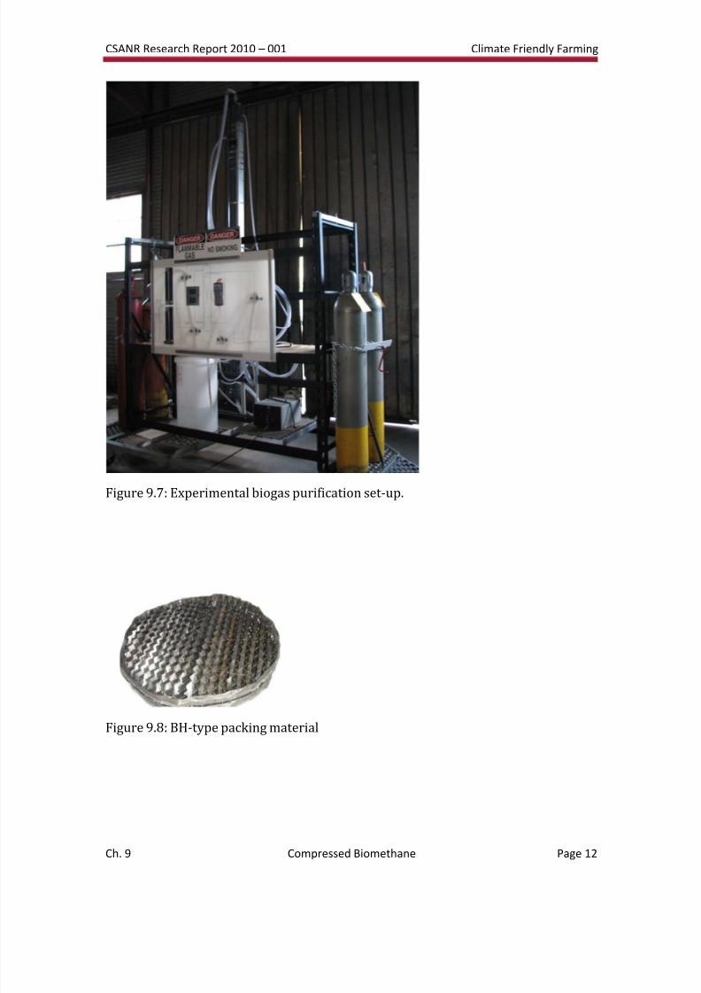
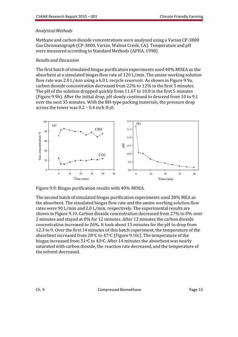
A laboratory-scale biogas purification tower (3.5 m tall) was constructed (Figure9.7) using 1.57x10⁻² m3 of BH-type packing. This packing was used to increase thetransfer efficiency of carbon dioxide between simulated biogas and an amineworking solution. The BH-type packing, shown in Figure 9.8, is characterized bychemically treated wave-like corrugated sheet surfaces with specific geometricareas ranging up to 2000 m2/m3 (Lei et al., 2009). The tower was operated in batchmode by spraying an amine working solution from the top through a distributoronto the packing material surface, allowing the working solution to contact thesimulated biogas for a specific period of time, and then collecting the working
solution at the bottom.Biogas was simulated by combining methane cylinder gas with carbon dioxidecylinder gas in various ratios. The biogas, introduced at the bottom of the tower,flows up through the packing material, interacts with the amine working solution,and then flows out near the top. Thermocouples were installed at both the top andthe bottom of the tower for monitoring of operating temperatures. Before eachbatch experiment, air was removed from the system using a nitrogen purge andthen nitrogen was removed using the simulated biogas mixture. Gas samples werecollected in vacuum polypropylene bags during the experiments. A baseline amineworking solution sample was taken prior to beginning the experiment. Severalamine types and concentrations were tested for their efficacy in removing CO2 fromthe biogas.
8/3/2019 CSANR2010-001.Ch09
http://slidepdf.com/reader/full/csanr2010-001ch09 12/24
CSANR Research Report 2010 – 001 Climate Friendly Farming
Ch. 9 Compressed Biomethane Page 12
Figure 9.7: Experimental biogas purification set-up.
Figure 9.8: BH-type packing material
8/3/2019 CSANR2010-001.Ch09
http://slidepdf.com/reader/full/csanr2010-001ch09 13/24
CSANR Research Report 2010 – 001 Climate Friendly Farming
Ch. 9 Compressed Biomethane Page 13
Analytical Methods
Methane and carbon dioxide concentrations were analyzed using a Varian CP-3800Gas Chromatograph (CP-3800, Varian, Walnut Creek, CA). Temperature and pHwere measured according to Standard Methods (APHA, 1998).
Results and Discussion
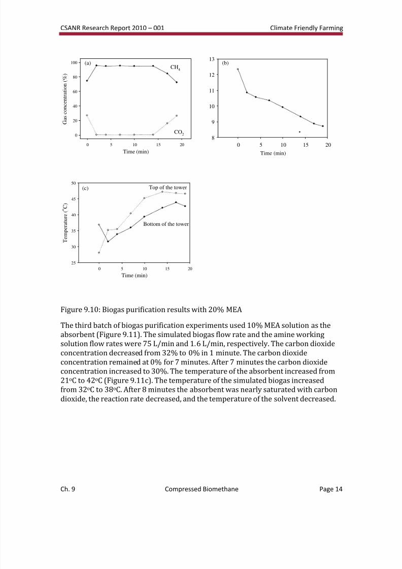
The first batch of simulated biogas purification experiments used 40% MDEA as theabsorbent at a simulated biogas flow rate of 120 L/min. The amine working solutionflow rate was 2.0 L/min using a 6.0 L recycle reservoir. As shown in Figure 9.9a,carbon dioxide concentration decreased from 22% to 12% in the first 5 minutes.The pH of the solution dropped quickly from 11.67 to 10.0 in the first 5 minutes(Figure 9.9b). After the initial drop, pH slowly continued to descend from 10 to 9.1over the next 35 minutes. With the BH-type packing materials, the pressure dropacross the tower was 0.2 – 0.4 inch H2O.
Time (min)
0 10 20 30 40 50
G a s c o n c e n t r a t i o n %
0
20
40
60
80
100
CH4
CO2
(a)
Time (min)
0 10 20 30 40
p H
9.0
9.5
10.0
10.5
11.0
11.5
12.0(b)
Figure 9.9: Biogas purification results with 40% MDEA.
The second batch of simulated biogas purification experiments used 20% MEA asthe absorbent. The simulated biogas flow rate and the amine working solution flowrates were 90 L/min and 2.0 L/min, respectively. The experimental results areshown in Figure 9.10. Carbon dioxide concentration decreased from 27% to 0% over2 minutes and stayed at 0% for 12 minutes. After 12 minutes the carbon dioxideconcentration increased to 26%. It took about 15 minutes for the pH to drop from12.3 to 9. Over the first 14 minutes of this batch experiment, the temperature of the
absorbent increased from 28oC to 47oC (Figure 9.10c). The temperature of thebiogas increased from 31oC to 43oC. After 14 minutes the absorbent was nearlysaturated with carbon dioxide, the reaction rate decreased, and the temperature of the solvent decreased.
8/3/2019 CSANR2010-001.Ch09
http://slidepdf.com/reader/full/csanr2010-001ch09 14/24
CSANR Research Report 2010 – 001 Climate Friendly Farming
Ch. 9 Compressed Biomethane Page 14
Time (min)
0 5 10 15 20
G a s c o n c e n
t r a t i o n ( % )
0
20
40
60
80
100CH
4
CO2
(a)
Time (min)
0 5 10 15 20
8
9
10
11
12
13(b)
Time (min)
0 5 10 15 20
T e m p e r a t u r e ( o C )
25
30
35
40
45
50Top of the tower
Bottom of the tower
(c)
Figure 9.10: Biogas purification results with 20% MEA
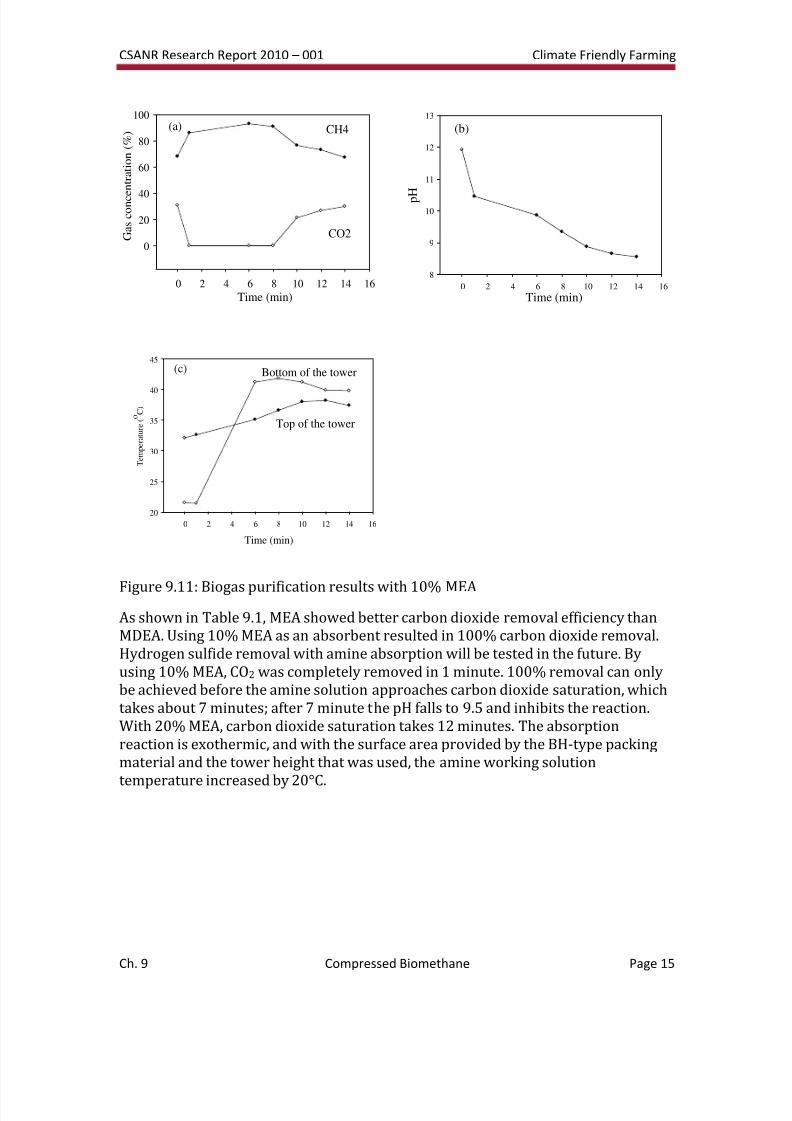
The third batch of biogas purification experiments used 10% MEA solution as theabsorbent (Figure 9.11). The simulated biogas flow rate and the amine workingsolution flow rates were 75 L/min and 1.6 L/min, respectively. The carbon dioxideconcentration decreased from 32% to 0% in 1 minute. The carbon dioxideconcentration remained at 0% for 7 minutes. After 7 minutes the carbon dioxideconcentration increased to 30%. The temperature of the absorbent increased from21oC to 42oC (Figure 9.11c). The temperature of the simulated biogas increasedfrom 32oC to 38oC. After 8 minutes the absorbent was nearly saturated with carbon
dioxide, the reaction rate decreased, and the temperature of the solvent decreased.
8/3/2019 CSANR2010-001.Ch09
http://slidepdf.com/reader/full/csanr2010-001ch09 15/24
CSANR Research Report 2010 – 001 Climate Friendly Farming
Ch. 9 Compressed Biomethane Page 15
0 2 4 6 8 10 12 14 16
0
20
40
60
80
100
G a s c o n c e n t r a t i o n ( % )
Time (min)
CH4
CO2
(a)
Time (min)0 2 4 6 8 10 12 14 16
p H
8
9
10
11
12
13
(b)
Time (min)
0 2 4 6 8 10 12 14 16
T e m p e r a t u r e ( o C )
20
25
30
35
40
45
Bottom of the tower
Top of the tower
(c)
Figure 9.11: Biogas purification results with 10% MEA
As shown in Table 9.1, MEA showed better carbon dioxide removal efficiency thanMDEA. Using 10% MEA as an absorbent resulted in 100% carbon dioxide removal.Hydrogen sulfide removal with amine absorption will be tested in the future. Byusing 10% MEA, CO2 was completely removed in 1 minute. 100% removal can onlybe achieved before the amine solution approaches carbon dioxide saturation, whichtakes about 7 minutes; after 7 minute the pH falls to 9.5 and inhibits the reaction.With 20% MEA, carbon dioxide saturation takes 12 minutes. The absorptionreaction is exothermic, and with the surface area provided by the BH-type packingmaterial and the tower height that was used, the amine working solution
temperature increased by 20°C.
8/3/2019 CSANR2010-001.Ch09
http://slidepdf.com/reader/full/csanr2010-001ch09 16/24
CSANR Research Report 2010 – 001 Climate Friendly Farming
Ch. 9 Compressed Biomethane Page 16
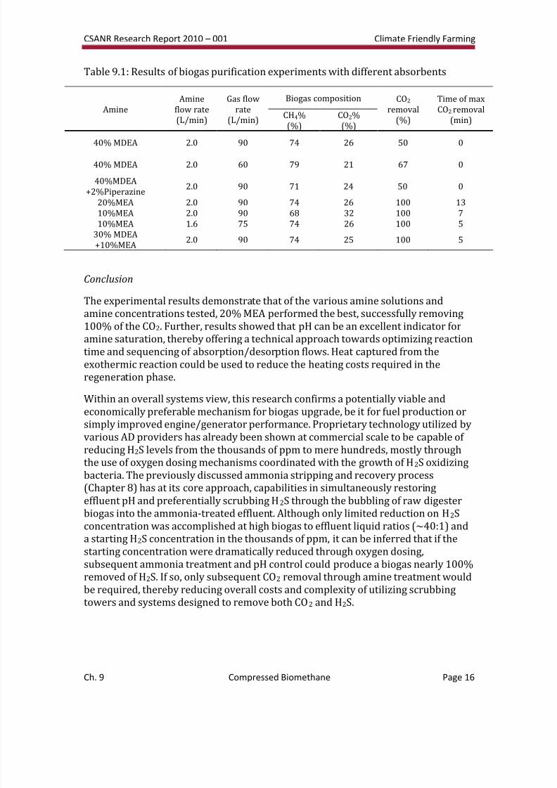
Table 9.1: Results of biogas purification experiments with different absorbents
AmineAmine
flow rate(L/min)
Gas flowrate
(L/min)
Biogas composition CO2 removal
(%)
Time of maxCO2 removal
(min)CH4%(%)
CO2%(%)
40% MDEA 2.0 90 74 26 50 0
40% MDEA 2.0 60 79 21 67 0
40%MDEA+2%Piperazine
2.0 90 71 24 50 0
20%MEA 2.0 90 74 26 100 1310%MEA 2.0 90 68 32 100 710%MEA 1.6 75 74 26 100 5
30% MDEA+10%MEA
2.0 90 74 25 100 5
Conclusion
The experimental results demonstrate that of the various amine solutions andamine concentrations tested, 20% MEA performed the best, successfully removing100% of the CO2. Further, results showed that pH can be an excellent indicator foramine saturation, thereby offering a technical approach towards optimizing reactiontime and sequencing of absorption/desorption flows. Heat captured from theexothermic reaction could be used to reduce the heating costs required in theregeneration phase.
Within an overall systems view, this research confirms a potentially viable and
economically preferable mechanism for biogas upgrade, be it for fuel production orsimply improved engine/generator performance. Proprietary technology utilized byvarious AD providers has already been shown at commercial scale to be capable of reducing H2S levels from the thousands of ppm to mere hundreds, mostly throughthe use of oxygen dosing mechanisms coordinated with the growth of H2S oxidizingbacteria. The previously discussed ammonia stripping and recovery process(Chapter 8) has at its core approach, capabilities in simultaneously restoringeffluent pH and preferentially scrubbing H2S through the bubbling of raw digesterbiogas into the ammonia-treated effluent. Although only limited reduction on H2Sconcentration was accomplished at high biogas to effluent liquid ratios (~40:1) anda starting H2S concentration in the thousands of ppm, it can be inferred that if the
starting concentration were dramatically reduced through oxygen dosing,subsequent ammonia treatment and pH control could produce a biogas nearly 100%removed of H2S. If so, only subsequent CO2 removal through amine treatment wouldbe required, thereby reducing overall costs and complexity of utilizing scrubbingtowers and systems designed to remove both CO2 and H2S.
8/3/2019 CSANR2010-001.Ch09
http://slidepdf.com/reader/full/csanr2010-001ch09 17/24
CSANR Research Report 2010 – 001 Climate Friendly Farming
Ch. 9 Compressed Biomethane Page 17
Preliminary Pilot-Scale Trials of Biogas Purification (Western Washington
University)
While WSU conducted targeted research on using chemical solvents to exclusivelyremove CO2 as its integrated nutrient recovery process was designed to pre-treat the H2S, WWU conducted its own pilot-scale research comparing two base methodsfor removing H2S and CO2. Beginning in 2004, Western Washington University’sVehicle Research Institute (WWU-VRI) surveyed two processes for upgrading biogasto biomethane, a sodium hydroxide system and a diethanolamine system.
Sodium Hydroxide System
The first system used sodium hydroxide because it reacts with both hydrogensulfide and carbon dioxide but not with methane. A three tower system wasconstructed, consisting of a first stage with iron filings, a second stage with sodiumhydroxide, and a third stage of desiccant. The first tower used a polyvinyl chloride(PVC) pipe with a 100 mm inside diameter and a 3 m height. The tower was packed
with machine shop tailings of iron and steel, as hydrogen sulfide reacts with ironoxide to form iron sulfide. The biogas entered the tower from the bottom through a19 mm hose. The second tower used a 300 mm inside diameter PVC pipe of 1.8 mheight. A 10% solution of sodium hydroxide was sprayed from the top of the tower.Polyethylene balls of 25 mm provide a large surface area to increase thebiogas/liquid interaction. The biogas rises from the bottom and the carbon dioxidereacts with the sodium hydroxide to form sodium carbonate. The third tower was0.6 m tall and 250 mm inside diameter, and filled with desiccant to remove watervapor from the biogas. The biomethane was then compressed to 1700 psi andcollected in storage tanks. An intermediate tank was used as an oil trap. The PVCconstruction is low cost and resistant to the corrosive effects of hydrogen sulfide. It
was determined that epoxy was required to seal PVC seams and joints when dealingwith raw biogas.
Analytical Methods
Biogas from the Vander Haak Dairy (Lynden, WA) anaerobic digester and theupgraded biomethane from the sodium hydroxide system were sampled in test bags. The bags were tested in the gas chromatograph at the Conoco Philips refineryin Ferndale, Washington.
Results and Discussion
The inlet biogas was roughly 60% methane, 40% carbon dioxide and 3500 ppmhydrogen sulfide. The sodium hydroxide system improved methane concentrationfrom roughly 60% to 94%. The caustic solution corroded the spray system, whichrequired cleaning after only two to three hours of operation. After six to eight hours,the caustic solution became saturated with carbon dioxide and was no longer able toremove hydrogen sulfide or carbon dioxide. Results of three testing periods areshown in Table 9.2.
8/3/2019 CSANR2010-001.Ch09
http://slidepdf.com/reader/full/csanr2010-001ch09 18/24
CSANR Research Report 2010 – 001 Climate Friendly Farming
Ch. 9 Compressed Biomethane Page 18
Table 9.2: Sample results from the first refinery
Sample Date CH4 CO2 H2S N ORaw 4/28/2006 60.59% 36.03% 0.34% 2.50% 0.53%1 4/28/2006 93.62% 2.05% <1000 ppm 3.29% 0.77%
2 5/4/2006 57.38% 40.76% <1000 ppm 1.52% 0.34%3 5/4/2006 56.06% 41.76% 0.35% 1.48% 0.35%Tank 1 5/5/2006 81% 15.03% 900ppm 2.26% 0.37%Tank 2 5/5/2006 83.46% 11.51% 850ppm 2.97% 0.57%Tank 3 5/5/2006 75.28% 14.54% <1000 ppm 7.46% 1.47%
A sample of the raw biogas was taken prior to the refinery inlet. Samples 1 – 3 weretaken at the outlet. Sample 1 was taken twenty minutes after system startup,whereas Samples 2 and 3 were taken after more than eight hours of operation andshow the degraded performance of the system. Tank samples 1 – 3 show methanelevels taken from the storage tanks at 100 bar pressure following compression.
Hydrogen sulfide levels remain below 1000 ppm in all of the tests (except rawbiogas). This may represent hydrogen sulfide reduction from the operation of aniron filing tower alone. The sodium hydroxide appeared to be loaded with carbondioxide during most of the tests.
Conclusion
Although team was encouraged by the initial test results, the results shown aboveindicate that the sodium hydroxide system is not appropriate for a refinery, as theneed for continuous addition of sodium hydroxide solution seems unworkable. Inaddition, the gas with ~900 ppm hydrogen sulfide stored in tanks over a three
month period caused tank valves to seize, ultimately requiring replacements.Diethanolamine System
Two subsequent pilot refinery units relied on amine-based recovery, whichultimately was combined with a biological process. It is hoped that this will result inlower costs for biogas upgrading.
The first diethalanolamine system was constructed to be transportable (to meet therequirements of the EPA People, Prosperity, and Planet award competition held inWashington D.C.). After a design phase and a physical mock-up, the second refinerywas built with eight, 2 m long PVC tubes of 100 mm inside diameter. The tubes were
arrayed vertically in a two by four pattern as viewed from above. High surface areapolyethylene balls, injection molded by students, filled each tower. A 19 mmdiameter fitting at the bottom of the first tube allowed raw biogas to enter. Thebiogas traveled upward through the 25 mm polyethylene balls in the first tower andthen downward to the next tube in a 19 mm high velocity connector tube. A total of 200 liters of DEA solution was sprayed from the top of each tube at a rate of 4 to 10liters per minute. Gas sampling ports were built into the system after the first tube
8/3/2019 CSANR2010-001.Ch09
http://slidepdf.com/reader/full/csanr2010-001ch09 19/24
CSANR Research Report 2010 – 001 Climate Friendly Farming
Ch. 9 Compressed Biomethane Page 19
and then after every second tube. Four sampling ports were provided between thetubes.
Analytical Methods
Samples were taken and analyzed at the BP Cherry Point refinery gas
chromatograph. Results are shown in Figure 9.12.
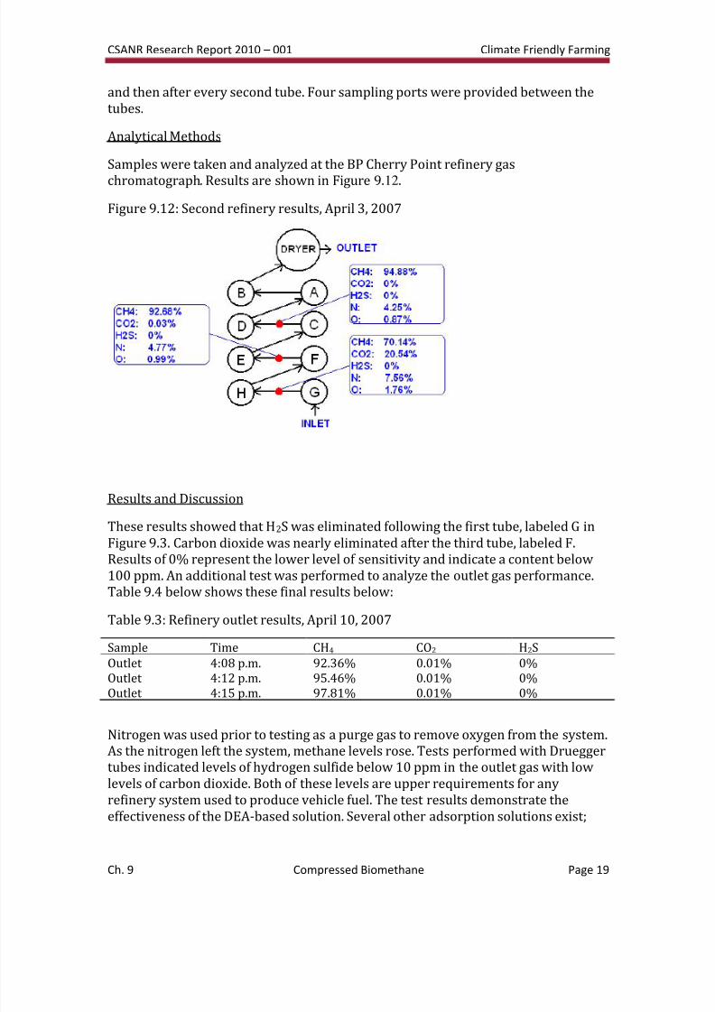
Figure 9.12: Second refinery results, April 3, 2007
Results and Discussion
These results showed that H2S was eliminated following the first tube, labeled G inFigure 9.3. Carbon dioxide was nearly eliminated after the third tube, labeled F.Results of 0% represent the lower level of sensitivity and indicate a content below100 ppm. An additional test was performed to analyze the outlet gas performance.Table 9.4 below shows these final results below:
Table 9.3: Refinery outlet results, April 10, 2007
Sample Time CH4 CO2 H2S
Outlet 4:08 p.m. 92.36% 0.01% 0%Outlet 4:12 p.m. 95.46% 0.01% 0%Outlet 4:15 p.m. 97.81% 0.01% 0%
Nitrogen was used prior to testing as a purge gas to remove oxygen from the system.As the nitrogen left the system, methane levels rose. Tests performed with Drueggertubes indicated levels of hydrogen sulfide below 10 ppm in the outlet gas with lowlevels of carbon dioxide. Both of these levels are upper requirements for anyrefinery system used to produce vehicle fuel. The test results demonstrate theeffectiveness of the DEA-based solution. Several other adsorption solutions exist;
8/3/2019 CSANR2010-001.Ch09
http://slidepdf.com/reader/full/csanr2010-001ch09 20/24
CSANR Research Report 2010 – 001 Climate Friendly Farming
Ch. 9 Compressed Biomethane Page 20
some may prove superior to DEA. DEA was chosen due to its ability to absorb largequantities of carbon dioxide and still adsorb hydrogen sulfide.
Conclusion
Although the system successfully upgraded biogas, several operational challenges
remained, that are being addressed in a farm-scale pilot system being installed at VanDerHaak Dairy in Lynden, WA. Specifically, the design of the system (with eight separate 2 m towers) created issues with pressure drops, and difficulties inbalancing the flow and fluid levels in each tower. Unfortunately, the DEA workingsolution pump was directly plumbed to a spray head at the top of each tube. Eachspray head could be individually throttled, but there was no return line from thespray head array to the DEA sump. As a result, attempts to reduce and balance theflow at each spray head led to an increase in system pressure, and ultimately, leaksand joint failures. These design issues were addressed in the third refinery unit,designed for pilot scale operation.
Pilot-Scale Biogas Purification (Western Washington University)
The full pilot-scale refinery unit attempted to address the design limitationsdiscovered in the previous design, as well as to create a method for regenerating theDEA and fully treat the waste streams resulting from the process. The refinery wasbuilt at the same dairy in Lynden, WA where the initial anaerobic digester wasinstalled and tested, adjacent to the anaerobic digester. The current target is tooperate an Airporter Shuttle/Bellair Charter bus on biomethane.
The pilot scale refinery unit is currently in construction. It is designed to produce 25scfm of refined biomethane at nearly 250 bar (3600 psi) for storage in tanks. The
system will have provisions for both fast fill and time fill operations. The refinerydesign target could support up to 16 large buses or nearly 170 vehicles. Storagecapacity and amine regeneration rates will initially limit production to support up tofive large buses. The unit consists of two 6 m towers with 300 mm inside diameter.A DEA working solution sprays from the top of each tower onto a collection of highsurface area elements. Biogas enters each tower from the bottom. A 12 m (40 ft)double door shipping container is used to house two 28 scfm compressors, an amineregeneration unit, and a bioreactor system for processing hydrogen sulfide andcarbon dioxide. A control room will manage process flows automatically with aprogrammable logic control system. Racks of DOT cylinders will be stored on thetop of the container. The entire system sits on a concrete pad roughly 6 m by 12 m.
The system meets or exceeds all existing codes, especially NFPA 52.
To enable the design of the pilot scale refinery, three different investigations wereperformed. The first was a material study to analyze the corrosive effects of DEAsolutions loaded with hydrogen sulfide and carbon dioxide. The second was a studyof an amine regeneration unit, and the third was testing involving bioreactors. Theuse of the bioreactor is novel and requires protection from public disclosure.
8/3/2019 CSANR2010-001.Ch09
http://slidepdf.com/reader/full/csanr2010-001ch09 21/24
CSANR Research Report 2010 – 001 Climate Friendly Farming
Ch. 9 Compressed Biomethane Page 21
The material study focused on grade 316 stainless steel, PVC, and chemicallyresistant fiberglass composite as potential materials for the main refinery towers.Samples of each material were prepared and submerged in corrosive solutions forvarying lengths of time. The samples were observed under a scanning electronmicroscope and compared with samples that were not submerged. All three
materials showed minimal damage. The fiberglass was the least damaged and waschosen for the 6 m tubes over stainless steel as a result of this test and thesignificant cost savings achieved. The material study guided the selection of allrefinery related materials. Grade 316 stainless steel pipe in 25 mm diameter is usedfor all DEA lines while polyethylene (PE) will be used for some lines as well. Thechallenge with PE is the difficulty of forming corrosion resistant joints.
An amine regeneration unit was built in small scale to demonstrate the feasibility of regeneration. The process is used in oil refineries to remove hydrogen sulfide fromgas streams. The Klaus process is then used to process the hydrogen sulfide.Remaining hydrogen sulfide is then oxidized in a furnace. For the biomethane
refinery, the Klaus process was deemed too complex and expensive at small scaleand the furnace entirely unacceptable from an emission point of view. Theregeneration unit is still required to reuse the amine solution and separate thehydrogen sulfide and carbon dioxide. The test unit is designed to have an aminesolution enter a heat exchanger to heat up the incoming solution and reject heat from the outgoing solution. The amine working solution passes through a heatingvessel, where 10,000 BTU propane burners heat the vessel. As the amine solutionapproaches 100oC, the hydrogen sulfide and carbon dioxide de-adsorb and rise to avent. The amine solution passes back through the heat exchanger and returns to theamine solution sump. A motor controller was designed and fabricated at WWU tocontrol a pump for the amine solution that operates prior to the heat exchanger on
the inlet side. The vapor that leaves the heating vessel travels through a 2 m tubewith a 200 mm inside diameter, filled with polyethylene balls. A solution of sodiumhypochlorite sprays down upon the tower and polyethylene balls to react with thehydrogen sulfide. The remaining gas travels through an iron-filing-filled tube toremove any remaining hydrogen sulfide, while the carbon dioxide is allowed to passthrough. As of April 1, 2010, construction of the pilot facility was nearingcompletion.
Getting the upgraded biogas to the end user has also presented some challenges.Ultimately, the upgraded biogas should ideally be injected directly into an existingnatural gas pipeline system or (as a less-preferred solution) be hauled by tanker.
However, for this initial pilot study, a refueling rig will take biogas from the farm inLynden to the Airporter Shuttle/Bellair Charter bus depot in Ferndale, roughly 17miles away. (Concerns with border traffic made it infeasible for buses to fueldirectly at the farm.) The refueling rig has wiring for a generator and space for amobile natural gas compressor. It can hold up to ten compressed natural gas tanks,with a capacity of more than 200 GGE. The vehicle has been purchased, and thenecessary conversions are in the process of being completed.
8/3/2019 CSANR2010-001.Ch09
http://slidepdf.com/reader/full/csanr2010-001ch09 22/24
CSANR Research Report 2010 – 001 Climate Friendly Farming
Ch. 9 Compressed Biomethane Page 22
Unfortunately, the use of a refueling rig adds complexity and cost to the pilot project. As a tank array is used to fill a CNG vehicle’s fuel tank, the two fuel systemscome to pressure equilibrium. At this point, no further gas will flow into the CNGvehicle’s fuel tank and a significant quantity of fuel will remain in the storage tank array. Typically up to 40% of the fuel in the storage array may not be used. To
address this issue requires either larger storage facilities or a booster compressorthat regulating the fuel pressure down to an inlet pressure of a pump beforecompressing it back into a vehicle tank. Either solution is costly, requires additionalspace and weight on a mobile vehicle and uses additional energy for the boosterpump. This challenge would not occur if the vehicle could be fueled at the farm,where the compressor could be used to top off the vehicle.
Due to a variety of constraints on the way the funding for the vehicle can be spent,the vehicle chosen to run on upgraded biogas is a 2000-2003 year MCI F coach bus.Conversion will be completed by Cummings Northwest. In addition to this bus, aFord E250 bi-fuel van, with both gasoline and natural gas capability, was purchased
and will be updated with a compressed natural gas fuel injection.Finally, beyond the technical challenges, the team is providing assistance to developthe contract between the dairy and Airporter Shuttle/Bellair Charters for biogaspurchase and delivery. The team is leveraging experience gained from other localgovernments in buying and selling biomethane. The team is also working with theWhatcom Public Utility District No. 1.
Conclusion
Though technical obstacles remain, the team has made considerable progresstowards implementing a pilot-scale biogas purification facility next to a farm-scale
anaerobic digester. Overcoming the challenges continues to generate lessons that will be helpful to others aiming to implement similar technologies. Through theadditional revenue generated, biogas purification technologies have the potential toimprove the economic feasibility of anaerobic digestion, particularly in the PacificNorthwest, where prices received for electricity generation are relatively lowbecause of the abundance of cheap hydroelectric power in our region.
References
APHA, 2005. Standard Methods for the examination of water and wastewater, 21st Edition, American Public Health Association, Washington, D.C.
Biswas, T. D., A. R. S. Kartha, et al. (1977). Removal of carbon dioxide from biogas.Proceedings of national symposium on biogas technology and uses. NewDelhi, India, IARI.
Cavenati, S., Grande, C.A., Rodrigues, A.E., 2005. Upgrade of methane from landfillgas by pressure swing adsorption. Energy & Fuels, 19, 2545-2555.
8/3/2019 CSANR2010-001.Ch09
http://slidepdf.com/reader/full/csanr2010-001ch09 23/24
CSANR Research Report 2010 – 001 Climate Friendly Farming
Ch. 9 Compressed Biomethane Page 23
Chatterjee, G., Houde, A.A., Stern, S.A., 1997. Poly(ether urethane) and poly(etherurethane urea) membranes with high H2S/CH4 selectivity. Journal of
Membrane Science, 135, 99-106.
Chung, Y.C., Huang, C.P., Tseng, C.P., 1996. Operation optimization of Thiobacillusthioparus CH11 biofilter for hydrogen sulfide removal. Journal of
Biotechnology , 52, 31-38.
Davis, R. A. and O. C. Sandall (1993). "CO2/CH4 separation by facilitated transport inamine-polyethylene glycol mixtures." Aiche Journal 39(7): 1135-1145.
de Hullu, J., Maassen, J.I.W., van Meel, P.A., Shazad, S., Vaessen, J.M.P. (2008).Comparing different biogas upgrading techniques. Eindhoven University of Technology, The Netherlands.
Duan, H.Q., Koe, L.C.C., Yan, R., Chen, X.G., 2006. Biological treatment of H2S usingpellet activated carbon as a carrier of microorganisms in a biofilter. Water
Research, 40, 2629-2636.
ENGVA. 2004. Worldwide Natural Gas Vehicle Statistics. [web publication].http://www.ngvaeurope.eu/worldwide-ngv-statistics. ENGVA Europe,Madrid, Spain. Accessed May 19, 2010.
Godini, H. R. and D. Mowla (2008). "Selectivity study of H2S and CO2 absorptionfrom gaseous mixtures by MEA in packed beds." Chemical EngineeringResearch & Design 86(4A): 401-409.
Grande, C.A., Rodrigues, A.E., 2007. Biogas to fuel by vacuum pressure swingadsorption - I. Behavior of equilibrium and kinetic-based adsorbents.
Industrial & Engineering Chemistry Research, 46, 4595-4605.
Harasimowicz, M., Orluk, P., Zakrzewska-Trznadel, G., Chmielewskia, A.G., 2007.Application of polyimide membranes for biogas purification and enrichment.
Journal of Hazardous Materials, 144, 698-702
Kim, H.S., Kim, Y.J., Chung, J.S., Xie, Q., 2002. Long-term operation of a biofilter forsimultaneous removal of H2S and NH3. Journal of the Air & Waste
Management Association, 52, 1389-1398.
Kim, S., H. T. Kim, et al. (2004). "Optimization of CO2 absorption process with MEAsolution." Carbon Dioxide Utilization for Global Sustainability 153: 429-434.
Krumdieck, S., J. Wallace, et al. (2008). "Compact, low energy CO2 management using amine solution in a packed bubble column." Chemical EngineeringJournal 135(1-2): 3-9.
Lee, E.Y., Lee, N.Y., Cho, K.S., Ryu, H.W., 2006. Removal of hydrogen sulfide bysulfate-resistant Acidithiobacillus thiooxidans AZ11. Journal of Bioscience and
Bioengineering, 101, 309-314.
8/3/2019 CSANR2010-001.Ch09
http://slidepdf.com/reader/full/csanr2010-001ch09 24/24
CSANR Research Report 2010 – 001 Climate Friendly Farming
Lei, Z., Y. Yang, et al. (2009). "Catalytic distillation for the synthesis of tert-butylalcohol with structured catalytic packing " Catalysis Today 147(Supplement 1): S352-S356.
Lin, C. C. and K. S. Chien (2008). "Mass-transfer performance of rotating packed bedsequipped with blade packings in VOCs absorption into water." Separationand Purification Technology 63(1): 138-144.
Palmeri, N., Cavallaro, S., Bart, J.C.J., 2008. Carbon dioxide absorption by MEA - Apreliminary evaluation of a bubbling column reactor. Journal of Thermal
Analysis and Calorimetry , 91, 87-91.
Pinto, M.L., Pires, J., Rocha, J., 2008. Porous materials prepared from clays for theupgrade of landfill gas. Journal of Physical Chemistry C , 112, 14394-14402.
Pipatmanomai, S., Kaewluan, S., Vitidsant, T., 2009. Economic assessment of biogas-to-electricity generation system with H2S removal by activated carbon in
small pig farm. Applied Energy , 86, 669-674.
Rao, A. B. and E. S. Rubin (2002). "A technical, economic, and environmentalassessment of amine-based CO2 capture technology for power plant greenhouse gas control." Environmental Science & Technology 36(20): 4467-4475.
Soroushian, F., Shang, Y., Whitman, E.J., Garza, G., Zhang, Z., 2006. Development andapplication of biological H2S scrubbers for treatment of digester gas WEF'sAnnual Technical Exhibition and Conference, Texas, USA, pp. 3541-3547.
van der Zee, F.P., Villaverde, S., Garcia, P.A., Fdz-Polanco, F., 2007. Sulfide removal by
moderate oxygenation of anaerobic sludge environments. BioresourceTechnology , 98, 518-524.
Vannini, C., Munz, G., Mori, G., Lubello, C., Verni, F., Petroni, G., 2008. Sulphideoxidation to elemental sulphur in a membrane bioreactor: Performance andcharacterization of the selected microbial sulphur-oxidizing community.Systematic and Applied Microbiology , 31, 461-473.
Vijay, V. (1989). Studies on utilization of biogas for improved performance of duelfuel engine. Udaipur, India, College of Technology and Engineering. ME.