Embed Size (px)
Citation preview

Zero Boil‐Off Tank (ZBOT) Experiment
Joint CSA/ESA/JAXA/NASA Increments 47 and 48 Science
Symposium
19 – 21 January 2016
John McQuillenZBOT Project Scientist

ZBOT Team Contacts
Increment 47 & 48 Science Symposium
SCIENCEName Role Affiliation EmailDr. Mohammad Kassemi Principal Investigator Case Western
Reserve [email protected]
Dr. David Chato Co-Principal Investigator NASA [email protected]
Sonya Hylton Research Scientist Apogee Engineering, LLC
Dr. Olga Kartuzova Research Scientist Apogee Engineering, LLC
John McQuillen Project Scientist NASA [email protected]
MANAGEMENT
Name Role Affiliation EmailWilliam Sheredy Project Manager NASA [email protected]
Bart Gruber Project Lead Zin Technologies, Inc. [email protected]
2
ZBOT Project Team
Increment 47 & 48 Science Symposium 3
SCIENCE AND MANAGEMENTBill Sheredy– NASA GRC PMMohammad Kassemi – PI, CWRUDavid Chato - Co-Principal Investigator, NASA
Kevin Magee – Fluids Engineer, ZIN John Morrison – Software EngineerJim Ogrin – Mechanical Lead, ZINWilliam Pachinger – Electrical Engineer, ZINJim Paskert – Manufacturing Engineer, ZINJoseph Samrani – Electrical Lead, ZINChris Werner – Structural Engineer, ZINMichel Kahwaji Janho – Chemical Engineer, ZIN
Nechelle Grant - Risk Management, ARESRick Plastow– Software QA, BastionChris Bodzioney– Safety Engineer, ZINDarryl Seeley – Quality Assurance, ZIN
John McQuillen– Project Scientist, NASASonya Hylton – Research Scientist, ApogeeOlga Kartuzova – Research Scientist, ApogeeBart Gruber – Project Manager, ZIN
ENGINEERINGBernie Bolte – Electrical Engineer, ZINRobert Brock – Software Lead, ZINKimesha Calaway – Systems/Integration, ZINKevin Dendorfer – Electrical Technician, ZINJeff Eggers – Software Engineer, ZINAndrew Kawecki – Mechanical Technician, ZINAlex Kieckhafer – Thermal Engineer, ZIN
SAFETY and MISSION ASSURANCEAlex Beltram– RM Facilitator, ZINBrian Loucks– Quality Oversight, ARES

Science Background
NASA’s Cryogenic Fluid Management Challenges• Reliable cryogenic storage for use in propellant
systems is essential to meeting NASA’s future exploration goals.
• Heat leaks from surroundings lead to cryogen boil-off and excessive tank pressures.
• Tank is vented to reduce pressure, but also results in loss of cryogenic fluid.
• Predicting boil-off and self-pressurization rates is important to identify both active and passive techniques to minimize these losses.
Increment 47 & 48 Science Symposium 4

Significance of Cryogenic Research:Mars Mission Example
DRAFT14
12
10
8
6
4
2
Normalize
d Mass Savings
DRA 5.0 Reference
Maintenance & Spares
Nuclear Surface Power
ISRU Propellants
Closed‐Loop Life Support
Advanced Propulsion
Cargo Aerocapture at Mars
Improved Cryogenic Boil‐off
Notes:• Approximate results only. • Further assessments required.• Results are cumulative and thus dependent on
combinations/sequences of technologies applied• The change between points shows the relative mass savings for
that particular technology
• RED Text areas of Physical Science Impact
Advanced Avionics
• Physical sciences research on ISS provides the knowledge base for designing systems, ISS provides a platform to validate technologies for inclusion in flagship missions.
Increment 47 & 48 Science Symposium 5

1. Develop a small-scale simulant-fluid experiment for both preliminary ground-based testing and subsequent ISS flight experiments to obtain valuable microgravity empirical data for tank pressure control design and archival science data for model validation.
2. Build a science base for future space storage tank engineering efforts by elucidating the roles of the various interacting transport and phase change phenomena that impact tank pressurization and pressure control in variable gravity through systematic 1g and microgravity scientific investigation.
3. Develop, validate, and verify two-phase CFD models for tank pressure control that can be used to aid the future scale-up tank design.
4. Demonstrate the feasibility of Zero-Boil-Off (ZBO) pressure control schemes for microgravity and variable gravity applications by examining the effect of forced mixing of the bulk liquid on destratification and pressure reduction in a ventlessDewar.
ZBOT Science Objectives
Increment 47 & 48 Science Symposium 6

ZBOT Measurement Approach
• Transparent test tank accommodates the simulant fluid (perfluoro-normal-pentane - C5F12), mixing nozzle, heaters, and sensors.
• Thermal conditions of the tank and fluid are controlled: The test tank is isolated inside a vacuum jacket by insulating supports.
• Resistance Temperature Detectors (RTDs) and pressure transducers provide temperatures and pressures to assess the thermodynamic state of the test fluid.
• Fluid Support Unit provides flow and fine thermal conditioning of fluid.• Fluid Reservoir provides fluid storage and the ability to change the fill
level in the tank per the test matrix.
Increment 47 & 48 Science Symposium 7

Data Acquisition and Control Unit
(DACU)
Fluid Reservoir
Thermal Control Unit
(TCU)
Cold Plate Package
(CPP)
Camera Package Mounting Location SAMS Head
Mounting Location
Test Section (14.0”W x 22.5”H
x 14.8”D)
Illumination Package
Not Shown: Particle Injector and MSG Window.
25.1”
35.7”
ZBOT in the MSG Engineering Unit(at NASA MSFC)
Increment 47 & 48 Science Symposium 8
Fluid Support Unit (FSU)

Vacuum Jacket
IlluminationWindow
Test Tank (ullage end)
Insulated Test Tank Supports
Camera Window
Strip Heaters
Mixing Nozzle
Cooling Jacket
Beam Dump
ZBOT Test Section
Tank Volume: 0.83 L Tank Diameter: 10 cm Tank Height : 20 cm.Ability to have localized and global heating.
Increment 47 & 48 Science Symposium 9

ZBOT Operational Overview
Increment 47 & 48 Science Symposium 10
ZBOT Operational Scheme:1. Adjust tank fill level as necessary.2. Thoroughly mix tank contents to achieve initial uniform temperature
distribution in liquid.3. Heat tank
1. Use either tank wall heaters or radiate from vacuum jacket.2. Measure pressure and temperature rise.
4. Inject measured flow of controlled liquid temperature into tank.1. Measure pressure and temperature changes.2. Visualize jet penetration into ullage bubble.
5. Repeat as necessary (66 test points).
Technology Demonstration of Particle Imaging Velocimetry:6. Conduct tests after completing test matrix at 90% fill level.7. Inject particles as necessary.8. Repeat steps 2 – 5 but visualize particle flow patterns in steps 3 & 4
(32 test points).
Importance and Reason for ISS
Duration of microgravity test conditions:• Permits well-defined initial conditions to be established
for each test run.– Uniform Temperature– Quiescent
• Lack of buoyancy-driven convection establishes a fluid stratification that is significantly different than in a terrestrial environment.
• Significant curvature of ullage bubble in reduced gravity cannot be established in normal gravity environment.
• Bubble position within tank can be influenced by both liquid jet and Marangoni flows.
Increment 47 & 48 Science Symposium 11

Key Questions and Impact on Advancing the Field
• How much natural mixing (buoyancy vs. surface tension-driven) will take place in a given tank during operation at various gravitational levels?
• How much forced mixing is needed to thermally de-stratify the tanks without active cooling?
• Under what conditions will it be necessary to augment the thermal destratification through active cooling?
• How effectively do mixing-only and/or mixing-with-active-cooling decrease the pressure reduction times?
Need: reliable engineering correlations for mixing, destratification, and pressure reduction times as functions of relevant tank parameters such as heat leak rates, mixing flow rates, and fill levels
Application: sizing of the pumps, determining forced mixing modes, possible placement of flow control structures, and sizing and implementation of the active cooling mechanisms (TVS, Cryocooler, etc.)
Increment 47 & 48 Science Symposium 12

Benefits/Spin‐off Applications
• Space:– Reduced propellant launch mass (cost) and decreased risks
for future space missions by aiding the development of dynamic pressure control schemes for long-term storage of cryogenic fluids.
– Increased design reliability by providing archival data for benchmarking and improving computational fluid dynamic models used by the cryogenic fluid management community and aerospace companies for future tank designs.
• Earth Benefit– Advances the state-of-the-art knowledge in cryogenic fluid
management and two-phase flow and heat transfer.
Increment 47 & 48 Science Symposium 13

pBackup Charts
Increment 47 & 48 Science Symposium 14

• Perfluoro-n-Pentane (PnP, or C5F12)• High purity (99.7% straight-chained n-isomer).• Non-flammable, non-toxic, refrigerant/cleaning
fluid.• Physical properties
o Boiling Point = 29°C @ 1 atmo Vapor Pressure = 12.5 psia @ 25°Co Liquid Density ~ 1.6 g/cm3
o Liquid Viscosity ~ 0.6 cPo Surface Tension ~ 9 dynes/cmo ∆Hvap ~ 90J/go Liquid Specific Heat ~ 1.09 J/g°Co Liquid Thermal Conductivity ~ 0.056 W/m°C
• Benefits:o Relatively volatile at room temperatureo Tox 0 – Approved by JSC toxicology and
MSFC ECLSS groups
PnP n-Isomer (Straight Chained) Chemical Structure
ZBOT Test Fluid
Increment 47 & 48 Science Symposium 15

ZBOT‐1 Measurements & Data
Increment 47 & 48 Science Symposium
Type of Test Method & Mode
Pressurization
Heater Strip
Vacuum Jacket Heating
Heater and VacuumJacket
Mixing OnlyUniform Temperature
After Self-Pressurization
Subcooled Mixing
Uniform Temperature
After Self-Pressurization
Outputs as Time Evolution
Pressure
Fluid Temperature (6 locations)
Wall Temperature (17 locations)
Jacket Temperature (21 locations)
Jet Penetration Depth
DPIV Velocity/Flow Structures
Input Variables (Tolerances)Heater Power(w/ in 5 mW RMS)
Vacuum Jacket Offset(+/- 0.2°C)
Fill Level(70% +/- 3%, 80% +/- 3%, 90% -3%)
Jet Temperature(+/- 0.25°C)
Jet Velocity/Flow rate (10% of reading)
16

17
PMMA (Acrylic) Test Tank Dome
Stainless Steel Test Tank Base
Test Section – Test Tank

ZBOT Simplified Fluids Schematic
Increment 47 & 48 Science Symposium 18
Membrane Contactor
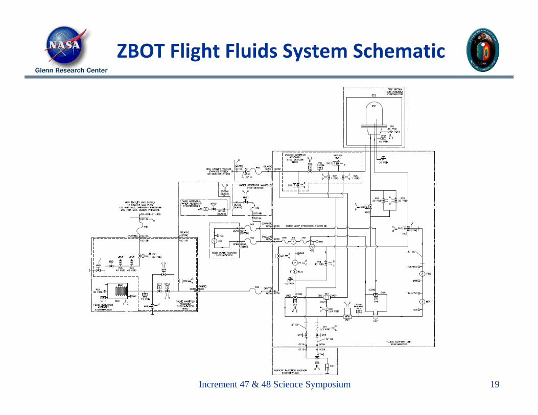
ZBOT Flight Fluids System Schematic
Increment 47 & 48 Science Symposium 19