Embed Size (px)
Citation preview
Page 1 56189_97_A
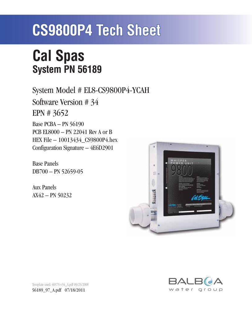
CS9800P4 Tech SheetCS9800P4 Tech Sheet
56189_97_A.pdf 07/18/2011Template used: 40575-v34_A.pdf 09/25/2008
Software Version # 34EPN # 3652Base PCBA – PN 56190PCB EL8000 – PN 22041 Rev A or BHEX File – 10013434_CS9800P4.hexConfiguration Signature – 4E6D2901
Base PanelsDB700 – PN 52659-05
Aux PanelsAX42 – PN 50232
Cal SpasSystem PN 56189
System Model # EL8-CS9800P4-YCAH
Page 2 56189_97_A
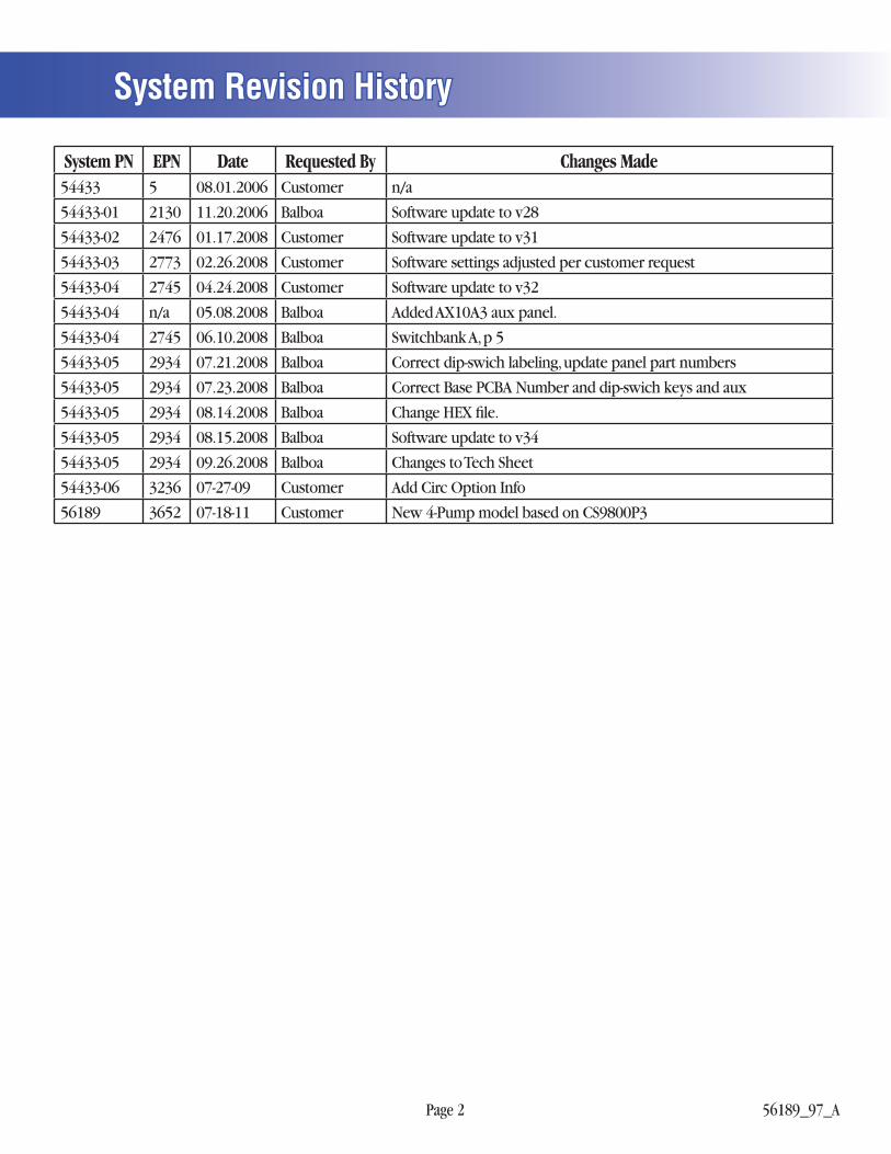
System Revision HistorySystem Revision History
System PN EPN Date Requested By Changes Made54433 5 08.01.2006 Customer n/a
54433-01 2130 11.20.2006 Balboa Software update to v28
54433-02 2476 01.17.2008 Customer Software update to v31
54433-03 2773 02.26.2008 Customer Software settings adjusted per customer request
54433-04 2745 04.24.2008 Customer Software update to v32
54433-04 n/a 05.08.2008 Balboa Added AX10A3 aux panel.
54433-04 2745 06.10.2008 Balboa Switchbank A, p 5
54433-05 2934 07.21.2008 Balboa Correct dip-swich labeling, update panel part numbers
54433-05 2934 07.23.2008 Balboa Correct Base PCBA Number and dip-swich keys and aux
54433-05 2934 08.14.2008 Balboa Change HEX fi le.
54433-05 2934 08.15.2008 Balboa Software update to v34
54433-05 2934 09.26.2008 Balboa Changes to Tech Sheet
54433-06 3236 07-27-09 Customer Add Circ Option Info
56189 3652 07-18-11 Customer New 4-Pump model based on CS9800P3
Page 3 56189_97_A
Power Requirements• 240VAC, 60Hz, 48A, Class A GFCI-protected service (Circuit Breaker rating = 60A max.)
• 4 wires (hot, hot, neutral, ground)
System Outputs
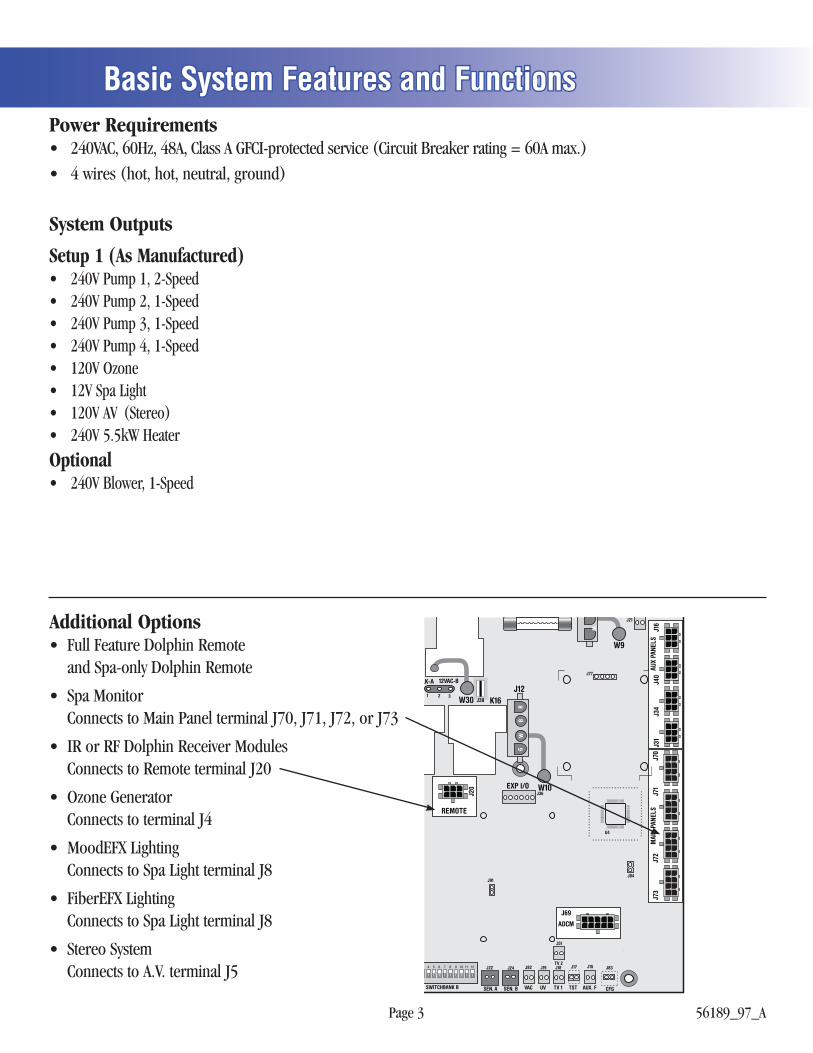
Basic System Features and FunctionsBasic System Features and Functions
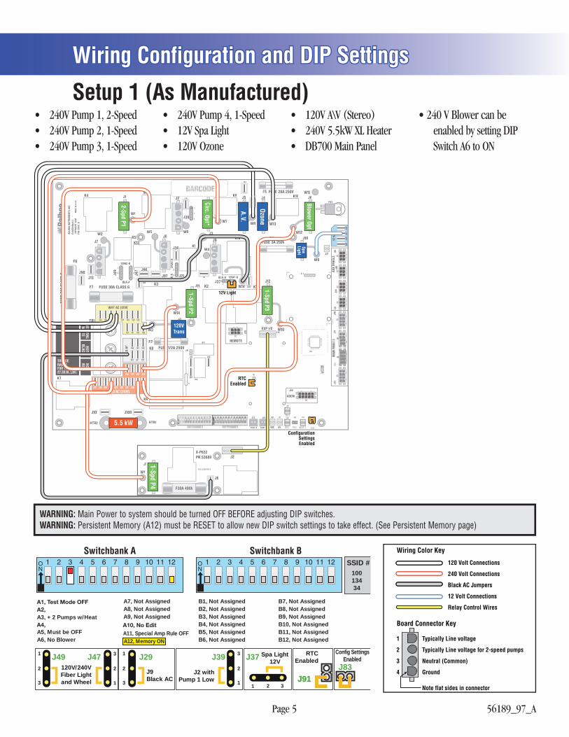
Setup 1 (As Manufactured)• 240V Pump 1, 2-Speed• 240V Pump 2, 1-Speed• 240V Pump 3, 1-Speed• 240V Pump 4, 1-Speed• 120V Ozone• 12V Spa Light• 120V AV (Stereo)• 240V 5.5kW Heater
Optional• 240V Blower, 1-Speed
Additional Options• Full Feature Dolphin Remote
and Spa-only Dolphin Remote
• Spa MonitorConnects to Main Panel terminal J70, J71, J72, or J73
• IR or RF Dolphin Receiver ModulesConnects to Remote terminal J20
• Ozone GeneratorConnects to terminal J4
• MoodEFX LightingConnects to Spa Light terminal J8
• FiberEFX LightingConnects to Spa Light terminal J8
• Stereo SystemConnects to A.V. terminal J5
K16J12
GR
BW
W30
W10
W9
SWITCHBANK B
J17
J84
J15 J83J22 J24 J82
TST AUX. F CFGSEN. A SEN. B VAC
J91
J21
TV 1
J51
TV 2
J36
J19 J18
UV
W
W
U4
REMOTE
EXP I/O
ADCM
J69
J20
J381 2 3
LK-A 12VAC-BJ77
MAI
N PA
NELS
AUX
PANE
LSJ1
6J4
0J3
4J3
1J7
3J7
2J7
1J7
0
Page 4 56189_97_A
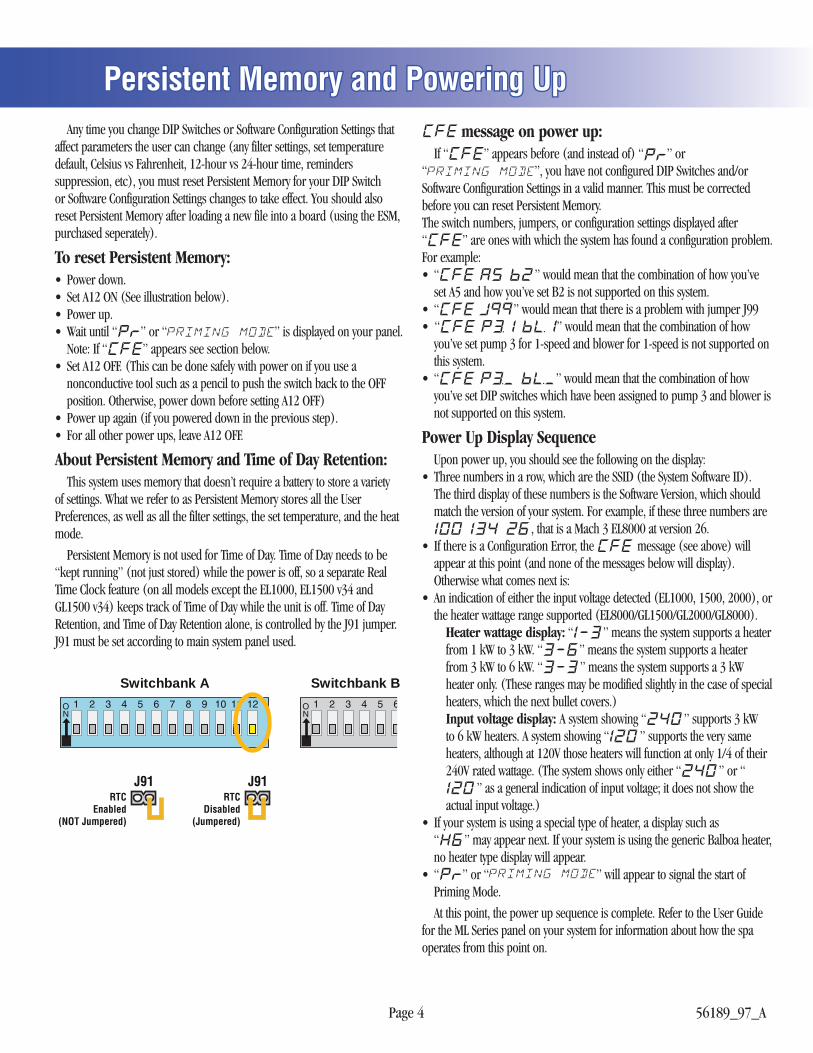
Persistent Memory and Powering UpPersistent Memory and Powering Up Any time you change DIP Switches or Software Configuration Settings that affect parameters the user can change (any filter settings, set temperature default, Celsius vs Fahrenheit, 12-hour vs 24-hour time, reminders suppression, etc), you must reset Persistent Memory for your DIP Switch or Software Configuration Settings changes to take effect. You should also reset Persistent Memory after loading a new file into a board (using the ESM, purchased seperately).
To reset Persistent Memory:• Power down.• Set A12 ON (See illustration below).• Power up.• Wait until “ ” or “ ” is displayed on your panel.
Note: If “ ” appears see section below.• Set A12 OFF. (This can be done safely with power on if you use a
nonconductive tool such as a pencil to push the switch back to the OFF position. Otherwise, power down before setting A12 OFF)
• Power up again (if you powered down in the previous step).• For all other power ups, leave A12 OFF.
About Persistent Memory and Time of Day Retention: This system uses memory that doesn’t require a battery to store a variety of settings. What we refer to as Persistent Memory stores all the User Preferences, as well as all the filter settings, the set temperature, and the heat mode.
Persistent Memory is not used for Time of Day. Time of Day needs to be “kept running” (not just stored) while the power is off, so a separate Real Time Clock feature (on all models except the EL1000, EL1500 v34 and GL1500 v34) keeps track of Time of Day while the unit is off. Time of Day Retention, and Time of Day Retention alone, is controlled by the J91 jumper. J91 must be set according to main system panel used.
message on power up: If “ ” appears before (and instead of) “ ” or“ ”, you have not configured DIP Switches and/or Software Configuration Settings in a valid manner. This must be corrected before you can reset Persistent Memory.The switch numbers, jumpers, or configuration settings displayed after “ ” are ones with which the system has found a configuration problem.For example:• “ ” would mean that the combination of how you’ve
set A5 and how you’ve set B2 is not supported on this system.• “ ” would mean that there is a problem with jumper J99• “ ” would mean that the combination of how
you’ve set pump 3 for 1-speed and blower for 1-speed is not supported on this system.
• “ ” would mean that the combination of how you’ve set DIP switches which have been assigned to pump 3 and blower is not supported on this system.
Power Up Display Sequence Upon power up, you should see the following on the display:• Three numbers in a row, which are the SSID (the System Software ID).
The third display of these numbers is the Software Version, which should match the version of your system. For example, if these three numbers are
, that is a Mach 3 EL8000 at version 26.• If there is a Configuration Error, the message (see above) will
appear at this point (and none of the messages below will display). Otherwise what comes next is:• An indication of either the input voltage detected (EL1000, 1500, 2000), or
the heater wattage range supported (EL8000/GL1500/GL2000/GL8000). Heater wattage display: “ ” means the system supports a heater
from 1 kW to 3 kW. “ ” means the system supports a heater from 3 kW to 6 kW. “ ” means the system supports a 3 kW heater only. (These ranges may be modified slightly in the case of special heaters, which the next bullet covers.)
Input voltage display: A system showing “ ” supports 3 kW to 6 kW heaters. A system showing “ ” supports the very same heaters, although at 120V those heaters will function at only 1/4 of their 240V rated wattage. (The system shows only either “ ” or “
” as a general indication of input voltage; it does not show the actual input voltage.)
• If your system is using a special type of heater, a display such as “ ” may appear next. If your system is using the generic Balboa heater, no heater type display will appear.
• “ ” or “ ” will appear to signal the start of Priming Mode.
At this point, the power up sequence is complete. Refer to the User Guide for the ML Series panel on your system for information about how the spa operates from this point on.
Switchbank A Switchbank B
J91RTC
Disabled(Jumpered)
J91RTC
Enabled(NOT Jumpered)
Page 5 56189_97_A
Wiring Configuration and DIP SettingsWiring Configuration and DIP Settings
WHT AC (120V)
BLK
AC
RED AC (240V)
J66 J65 J68
J64 J63 J67
J58 J57 J62 J54
J59 J60 J56 J61J74 J75 J53J95 J46 J55
J44 J52J28 J27 J35 J43 J23 J32TB1
FUSE 30A CLASS G
FUSE
30A
CLA
SS G
F6
F7
K7
HTR2 HTR1
K6
K8 FUSE 1/2A 250VF2
K4
K3 K2J37
K16
J7J8
K11K9 K10
GN
GN
GN
J9
J11
GN
J1
GN
GN
J12
GN
GN
GN
GN
J2
J3
J5 J6
J49
J47
BLK-A
BLK-
A
J39
K5K13
K1
K14W5
W4
W30
W14
W10
W6
W7 W8
W12
W9
W13
W15
W2
W1
W3
J84
J22
K12
K15
J86J92
J85
F1
J24 J82
SEN. ASE SEN. BE VAC
J91
J21
J36
TRC6
J19
UV
FUSE 20A 250V
J90
J94
J76J76
J93J93
FUSE 3A 250VF4
NG
J10
U4
REMOTE
EXP I/O
ADCM
J69
J20
J25
J38J38
J81
J45
J41
J33
1
1
22
3
3J29
1
1
2
2
3
3
12VAC-B
12VA
C-BB
BLK-A 12VAC-B
1
2
J89
J26 J48J50J42
J77
AUX
PANE
LS12
VAC
J16
J40
J34
J31
J73
J71
J70
TORQUE RANGEFOR TB1:27-30 IN. LBS.
HOTBLACK
NEUTRALW
HITEHOTRED
BALB
OA IN
STRU
MEN
TS, I
NC.
EL80
00 M
ach
3CO
PYRI
GHT
2006
P/N
2204
1_B
MAD
E IN
U.S
.A.
GN
J96J96
J101 J100
J13 J97
J30
GR
BW
J1
W1
J2
J6
F30A 480V
X-P632PN 53680
P/N 22909 REV B
1-Spd P45.5 kW
120VTrans
ConfigurationSettingsEnabled
RTCEnabled
A.V.
Ozone
12V Light
Spa Light
Circ. Opt*
Blower Opt
1-Spd P3
1-Spd P2
2-Spd P1
Setup 1 (As Manufactured)• 240V Pump 1, 2-Speed• 240V Pump 2, 1-Speed• 240V Pump 3, 1-Speed
• 240V Pump 4, 1-Speed• 12V Spa Light• 120V Ozone
• 120V A\V (Stereo)• 240V 5.5kW XL Heater• DB700 Main Panel
• 240 V Blower can be enabled by setting DIP Switch A6 to ON
120 Volt Connections
240 Volt Connections
Black AC Jumpers
12 Volt Connections
Relay Control Wires
Wiring Color Key
Typically Line voltage
Typically Line voltage for 2-speed pumps
Neutral (Common)
Ground
Note flat sides in connector
1
2
3
4
Board Connector Key
WARNING: Main Power to system should be turned OFF BEFORE adjusting DIP switches.WARNING: Persistent Memory (A12) must be RESET to allow new DIP switch settings to take effect. (See Persistent Memory page)
Switchbank A Switchbank B
B2, AssignableB3, AssignableB4, AssignableB5, AssignableB6, Assignable
A5, AssignableA6, Assignable
B1, AssignableB8, AssignableB9, AssignableB10, AssignableB11, AssignableB12, Assignable
B7, AssignableA8, AssignableA9, Assignable
A7, Assignable
A11, Special Amp Rule OFFA12, Memory ON
10013434
SSID #
1
2
3
1 2 33
2
1
3
2
13
2
1 J91J91J83
Config SettingsEnabled
RTCEnabled
Spa Light12V
J37
J2 withPump 1 Low
J39
J9 Black AC
J29120V/240VFiber Lightand Wheel
J49 J47
B2, Not AssignedB3, Not AssignedB4, Not AssignedB5, Not AssignedB6, Not Assigned
A5, Must be OFFA6, No Blower
B1, Not AssignedB8, Not AssignedB9, Not AssignedB10, Not AssignedB11, Not AssignedB12, Not Assigned
B7, Not AssignedA8, Not AssignedA9, Not Assigned
A7, Not Assigned
A3, + 2 Pumps w/Heat
Page 6 56189_97_A
DIP Switches DefinitionsDIP Switches DefinitionsWARNING:• Setting DIP switches incorrectly may cause abnormal system behavior and/or damage to system components.• Refer to Switchbank illustration on Wiring Configuration page for correct settings for this system.• Contact Balboa if you require additional configuration pages added to this tech sheet.
DIP Switchbank A KeyA1 ............... Test Mode (normally Off)A2 ............... In “ON” position, add one high-speed pump (or blower) with HeaterA3 ............... In “ON” position, add two high-speed pumps (or 1 HS Pump and Blower) with HeaterA4 ............... In “ON” position, add four high-speed pumps (or 3 HS Pumps and Blower) with HeaterA10 ............... When switched ON when spa is on, system will enter the Edit Menu for Configuration Settings Do not start spa with A10 turned on or CFE* error will occurA11 ............... In “ON” position, enables Special Amperage Rule, see "SA" in Software Configuration section for functionality with your system ............... In “OFF” position, disables Special Amperage RuleA12 ............... Persistent memory reset (used when spa is powering up) See "Persistent Memory and Powering Up" page
A2, A3, and A4 work in combination to determine the number of high-speed devices and blowers that can run before the heat is disabled. i.e. A2 and A3 in the ON position and A4 in the OFF position will allow the heater to operate with up to 3 high-speed pumps (or two HS Pumps and Blower) running at the same time. Heat is disabled when the fourth high-speed pump or blower is turned on.
Note: A2/A3/A4 all off = No heat with any high-speed pump or blower.
*CFE errors are illegal configurations such as a pump and a blower set to run on the same output. The configuration must be corrected before the spa will operate.
Assignable DIP Switch KeyA5 .............Must Be OFFA6 .............In “ON” position, Blower Enabled ..............In “OFF” position, Blower DisabledA7 . . . . . . Not AssignedA8 . . . . . . Not AssignedA9 . . . . . . Not AssignedB1 . . . . . . Not AssignedB2 . . . . . . Not AssignedB3 . . . . . . Not AssignedB4 . . . . . . Not AssignedB5 . . . . . . Not AssignedB6 . . . . . . Not AssignedB7 . . . . . . Not AssignedB8 . . . . . . Not AssignedB9 . . . . . . Not AssignedB10 . . . . . . Not AssignedB11 . . . . . . Not AssignedB12 . . . . . . Not Assigned
Page 7 56189_97_A
Jumper DefinitionsJumper Definitions
Jumpers Key
J29 . . . . . . . . . Jumper on Pins 1 and 2 will power J9-pin 1 (Mister) at 12 Volts AC. Jumper on Pins 2 and 3 will power J9-pin 1 (Mister) at 120/240 Volts AC. Note: W4 controls voltage on return line of J9-pin 3 and must be set for the same voltage.
J37 . . . . . . . . . Jumper on Pins 1 and 2 will power one leg of J10-pin 2 (Spa Light) at 120/240 Volts AC. Jumper on Pins 2 and 3 will power one leg of J10-pin 2 (Spa Light) at 12 Volts AC. Note: W9 controls voltage on the return line of J10-pin 1 and must be set for the same voltage.
J39 . . . . . . . . . Jumper on Pins 1 and 2 will power J2 pin 2 with Pump 1 Low. Jumper on Pins 2 and 3 will power J2 pin 2 with the Circ Pump. Note: W6 controls voltage on common line of J2-pin 3
J47 . . . . . . . . . Jumper on Pins 1 and 2 will power J8 pin 2 (Fiber Optic Light) and J7 at 120/240 Volts AC. Jumper on Pins 2 and 3 will power J8 pin 2 (Fiber Optic Light) at 12 Volts AC. Note: J47 and J49 must be set for the same voltage. W5 controls voltage on return line of J8-pin 3 and must be set to the same voltage.
J49 . . . . . . . . . Jumper on Pins 2 and 3 will power J8 pin 1 (Fiber Optic Wheel) at 120/240 Volts AC. Jumper on Pins 1 and 2 will power J8 pin 1 (Fiber Optic Wheel) at 12 Volts AC. Note: J47 and J49 must be set for the same voltage. W5 controls voltage on return line of J8-pin 3 and must be set to the same voltage.
J91 . . . . . . . . . Jumper on 1 Pin only enables Real Time Clock function, for use with time capable panels. Jumper on Pins 1 and 2 will disable RTC function, for use with non-time capable panels.
WARNING:• Setting DIP switches incorrectly may cause abnormal system behavior and/or damage to system components.• Refer to Switchbank illustration on Wiring Configuration page for correct settings for this system.• Contact Balboa if you require additional configuration pages added to this tech sheet.
Page 8 56189_97_A
Program Filter Cycles by Duration n Y _ n = Start and stop times; for time capable panels.
Y = Duration; for non-time capable panels _ = 1 DIP Switch
Pump 1 in Filter (w/Circ Pump) n Y (This feature is used in Circ Mode only.) Allows Pump 1 Low to operate in Filter Cycles to add extra filtration.
n = Normal; Y = Pump 1 with Circ
24-Hour Time* n Y _ n = 12-hour (am/pm); Y = 24-hour (military\European); _ = 1 DIP Switch
*Sets default for user preferences - only applies when persistent memory is reset (A12 On) during power-up.
Celsius** n Y _ n = Fahrenheit; Y = Celsius; _ = 1 DIP Switch
**Sets default for user preferences - only applies when persistent memory is reset (A12 On) during power-up
Timeouts 1 F 2 3 4 5 6 1-6 = 10, 20, 30, 40, 50, 60 minutes; F = 15 minutes
Pump 1 Low Timeout d 1 2 3 4 _ d = Use “Timeouts” value above; 1-4 = number of hours; _ = 3 DIP Switch
Light Timeout d 1 2 3 4 d = Use “Timeouts” value above; 1-4 = number of hours
Scrunch Panel n Y _ n = Normal panel layout;
Y = Alternate panel layout (ML900 scrunching enabled - ML550/700 Jets 3 replaces Blower; _ = 1 DIP Switch
Circ Type (behavior) n A 3 P _ n = Non circ or circ pump not plumbed with heater; A = 24-hour;
3 = 24-hour with 3ºF shutoff outside filter; P = Acts like Pump 1 Low (filter cycles, polls, etc.); _ = 2 DIP Switch
Software Configuration SettingsSoftware Configuration SettingsOEM Setting (Green circle)n =
Page 9 56189_97_A
Pump 1 Speeds 1 2 _ 1 = 1 speed; 2 = 2 speed; _ = 1 DIP Switch
Pump 2 Speeds 0 1 2 _ 0 = Disabled; 1 = On/Off; 2 = 2 speed; _ = 2 DIP Switch
Pump 3 Speeds 0 1 2 _ 0 = Disabled; 1 = On/Off; 2 = 2 speed; _ = 3 DIP Switch
Pump 4 Speeds 0 1 E H L _ 0 = Disabled; 1 = On/Off on board; E = External X-P or X-P231 board
H = On/Off on pin 1 of X-P632 board; L = 2 speed on X-P632 board; _ = 3 DIP Switch
Pump 5 Speeds 0 1 E L _ 0 = Disabled; 1 = On/Off on board; E = External X-P or X-P231 board
L = On/Off on pin 2 of X-P632 board; _ = 2 DIP Switch
Pump 6 Speeds 0 1 _ 0 = Disabled; 1 = On/Off; _ = 1 DIP Switch
Blower Speeds 0 1 2 3 _ 0 = Disabled; 1 = On/Off; 2 = 2 speeds; 3 = 3 speeds; _ = 2 DIP Switch
Separate Spa Light Buttons n Y _ See Chart Below (This feature applies when n = No Spa light button, Spa Light output is on with Fiber;
using Fiber Optic light) Y = Separate Spa Light button on ML900 or Aux panel _ = 1 DIP SwitchNote: The Light button on an ML900 panel is a SpaLight button. The Light button on most other panels is an EitherLight button.
Lb.n Lb.YFo.n No separately-controlled fi ber light; spa light enabled on both SpaLight and EitherLight buttons; fi ber light
(not wheel) comes on with spa light (at any intensity)
Fo.Y No separately-controlled fi ber light; fi ber light enabled on both FiberLight and EitherLight buttons; spa light comes on with fi ber light
Spa light and fi ber light each separately controlled; fi ber light enabled on both FiberLight and EitherLight buttons; spa light enabled on SpaLight buttons only
Spa Light On/Off n Y _ n = Dimmable (H, M, L) Light; Y = On/Off Light; _ = 1 DIP Switch
Fiber Optics n Y _ n = Disabled; Y = Light and Wheel Enabled;; _ = 2 DIP Switch
Software Configuration Settings ContinuedSoftware Configuration Settings ContinuedLI
GHTI
NG C
ONTR
OLPU
MP
SPEE
DS
Page 10 56189_97_A
Mister 1 n Y _ n = Mister Disabled;
Y = Mister Enabled on J9; _ = 1 DIP Switch
Mister 2 n Y _ n = Mister Disabled; Y = Mister Enabled on pin 1 of X-P632 board; _ = 1 DIP Switch
Mister 3 n Y _ n = Mister Disabled; Y = Mister Enabled on pin 2 of X-P632 board; _ = 1 DIP Switch
Option 1* n Y P _ n = Disabled; Y/P = Enabled on J9; _ = 2 DIP Switch
Option 2* n Y P _ n = Disabled; Y/P = Enabled on "alarm" relay; _ = 2 DIP Switch
Option 3* n Y P _ n = Disabled; Y/P = Enabled on pin 1 of X-P632 board; _ = 2 DIP Switch
Option 4* n Y P _ n = Disabled; Y/P = Enabled on pin 2 of X-P632 board; _ = 2 DIP Switch
Option 5* n Y P _ n = Disabled; Y/P = Enabled on J7; _ = 2 DIP Switch *Note: Options 1-5: Y = On/Off w/no timeout (toggle) mode; P = Pulse (momentary) mode
Cleanup Cycles** 0 1 2 3 4 0 = Disabled; 1-4 = Number of hours
**Sets default for user preferences - only applies when persistent memory is reset (A12 On) during power-up.
Cleanup Cycles as User Preference n Y n = Only in Configuration Settings; Y = Over-rideable by User via User Preferences
Ozone Operation A F _ A= Operates with Heater Pump (Pump 1 Low or Circ Pump);
F = Operates in Filter and Cleanup Cycles only; _ = 1 DIP Switch
Ozone Suppression n Y _ n = No Suppress; Y = 1-hour suppress on button press; _ = 1 DIP Switch
Ozone Icon n Y U n = Disabled; Y = Enabled ; U = Controlled by UV input
Software Configuration Settings ContinuedSoftware Configuration Settings ContinuedOZ
ONE
OPTI
ONS
Page 11 56189_97_A
Aux Button 1 (Bank A) 1 2 3 4 5 6 b g F E o t d P n A U r O H 9 L 8 7
Aux Button 2 (Bank A) 1 2 3 4 5 6 b g F E o t d P n A U r O H 9 L 8 7
Aux Button 3 (Bank A) 1 2 3 4 5 6 b g F E o t d P n A U r O H 9 L 8 7
Aux Button 4 (Bank A) 1 2 3 4 5 6 b g F E o t d P n A U r O H 9 L 8 7
1-6 = Assigns Pump Number (Pump 1, Pump 2, etc); b = Blower; g = Spa Light; F = Fiber-Optic wheel/light; E = EitherLight; o = Option 1; t = Mister 1; d = Mister 2/Cool; P = Mister 3/Elec Heat; n = Ext Heat; A = Sound Mode Select; U = Button Disabled; r = Air Valve; O = Option 2; H = Option 3; 9 = Invert; L = Option 4; 8 = Stir; 7 = Option 5
Aux Button 1 (Bank B) 1 2 3 4 5 6 b g F E o t d P n A U r O H 9 L 8 7
Aux Button 2 (Bank B) 1 2 3 4 5 6 b g F E o t d P n A U r O H 9 L 8 7
Aux Button 3 (Bank B) 1 2 3 4 5 6 b g F E o t d P n A U r O H 9 L 8 7
Aux Button 4 (Bank B) 1 2 3 4 5 6 b g F E o t d P n A U r O H 9 L 8 7
1-6 = Assigns Pump Number (Pump 1, Pump 2, etc); b = Blower; g = Spa Light; F = Fiber-Optic wheel/light; E = EitherLight; o = Option 1; t = Mister 1; d = Mister 2/Cool; P = Mister 3/Elec Heat; n = Ext Heat; A = Sound Mode Select; U = Button Disabled; r = Air Valve; O = Option 2; H = Option 3; 9 = Invert; L = Option 4; 8 = Stir; 7 = Option 5
Aux Button Bank Select A b _ A = Bank A; b = Bank B; _ = 1 DIP Switch
Suppress all Reminders n Y _ n = Display Reminders; Y = Suppress all Reminders; _ = 1 DIP Switch
Check pH Reminder Period 0 1 2 3 4 5 6 7 8 9 t
Check Sanitizer Reminder Period 0 1 2 3 4 5 6 7 8 9 t
Clean Filter Reminder Period 0 1 2 3 4 5 6 7 8 9 t
Test GFCI Reminder Period 0 1 2 3 4 5 6 7 8 9 t
Drain Water Reminder Period 0 1 2 3 4 5 6 7 8 9 t
Change Mineral Cartridge 0 1 2 3 4 5 6 7 8 9 t
Clean Cover Reminder Period 0 1 2 3 4 5 6 7 8 9 t
Treat Wood Reminder Period 0 1 2 3 4 5 6 7 8 9 t
Change Filter Reminder Period 0 1 2 3 4 5 6 7 8 9 t
0 = Off; 1 = 7 days; 2 = 14 days; 3 = 30 days; 4 = 45 days; 5 = 60 days; 6 = 90 days; 7 = 120 days; 8 = 180 days; 9 = 365 days; t = 21 days
Software Configuration Settings ContinuedSoftware Configuration Settings ContinuedRE
MIN
DERS
AUXI
LIAR
Y BU
TTON
S
Page 12 56189_97_A
Lowest Set Temperature* 8 7 8 = 80˚F/26.0˚C; 7 = 70˚F/21.0˚C
*Setting LS at 7 and Fr at 5 will cause a CFE error.
Default Set Temperature** 5 6 7 8 9 0 1 2 3 4 E F n
5 = 95˚F/35.0˚C; 6 = 96˚F/35.5˚C; 7 = 97˚F/36.0˚C; 8 = 98˚F/36.5˚C; 9 = 99˚F/37.0˚C; 0 = 100˚F/38.0˚C; 1 = 101˚F/38.5˚C; 2 = 102˚F/39.0˚C; 3 = 103˚F/39.5˚C; 4 = 104˚F/40.0˚C; E = 80˚F/26.5˚C; F = 85˚F/29.5˚C n = 90˚F/32.0˚C **Sets default for user preferences - only applies when persistent memory is reset (A12 On) during power-up.
Uppermost Set Temperature 5 6 7 8 9 0 1 2 3 4 E F n
5 = 95˚F/35.0˚C; 6 = 96˚F/35.5˚C; 7 = 97˚F/36.0˚C; 8 = 98˚F/36.5˚C; 9 = 99˚F/37.0˚C; 0 = 100˚F/38.0˚C; 1 = 101˚F/38.5˚C; 2 = 102˚F/39.0˚C; 3 = 103˚F/39.5˚C; 4 = 104˚F/40.0˚C; E = 80˚F/26.5˚C; F = 85˚F/29.5˚C n = 90˚F/32.0˚C
Freeze Temperature Threshold 3 4 9 5 3 = 39˚F/3.9˚C; 4 = 44˚F/6.7˚C; 9 = 49˚F/9.4˚C; 5 = 54˚F/12.2˚C;
Set Temperature Lock t S t = Temp Lock Only; S = Temp + Settings Lock
Software Configuration Settings ContinuedSoftware Configuration Settings ContinuedTE
MPE
RATU
RE S
ETTI
NGS
Page 13 56189_97_A
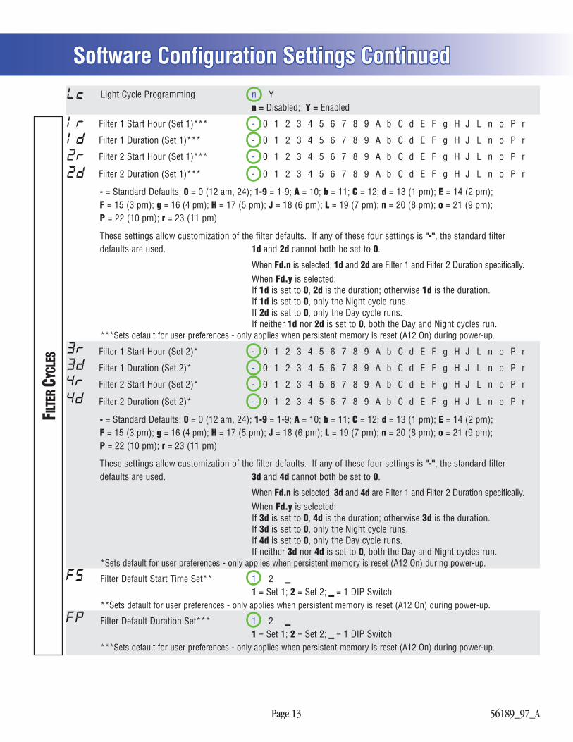
Light Cycle Programming n Y n = Disabled; Y = Enabled
Filter 1 Start Hour (Set 1)*** - 0 1 2 3 4 5 6 7 8 9 A b C d E F g H J L n o P r
Filter 1 Duration (Set 1)*** - 0 1 2 3 4 5 6 7 8 9 A b C d E F g H J L n o P r
Filter 2 Start Hour (Set 1)*** - 0 1 2 3 4 5 6 7 8 9 A b C d E F g H J L n o P r
Filter 2 Duration (Set 1)*** - 0 1 2 3 4 5 6 7 8 9 A b C d E F g H J L n o P r
- = Standard Defaults; 0 = 0 (12 am, 24); 1-9 = 1-9; A = 10; b = 11; C = 12; d = 13 (1 pm); E = 14 (2 pm); F = 15 (3 pm); g = 16 (4 pm); H = 17 (5 pm); J = 18 (6 pm); L = 19 (7 pm); n = 20 (8 pm); o = 21 (9 pm); P = 22 (10 pm); r = 23 (11 pm)
These settings allow customization of the filter defaults. If any of these four settings is "-", the standard filter defaults are used. 1d and 2d cannot both be set to 0.
When Fd.n is selected, 1d and 2d are Filter 1 and Filter 2 Duration specifically. When Fd.y is selected: If 1d is set to 0, 2d is the duration; otherwise 1d is the duration. If 1d is set to 0, only the Night cycle runs. If 2d is set to 0, only the Day cycle runs. If neither 1d nor 2d is set to 0, both the Day and Night cycles run. ***Sets default for user preferences - only applies when persistent memory is reset (A12 On) during power-up.
Filter 1 Start Hour (Set 2)* - 0 1 2 3 4 5 6 7 8 9 A b C d E F g H J L n o P r
Filter 1 Duration (Set 2)* - 0 1 2 3 4 5 6 7 8 9 A b C d E F g H J L n o P r
Filter 2 Start Hour (Set 2)* - 0 1 2 3 4 5 6 7 8 9 A b C d E F g H J L n o P r
Filter 2 Duration (Set 2)* - 0 1 2 3 4 5 6 7 8 9 A b C d E F g H J L n o P r
- = Standard Defaults; 0 = 0 (12 am, 24); 1-9 = 1-9; A = 10; b = 11; C = 12; d = 13 (1 pm); E = 14 (2 pm); F = 15 (3 pm); g = 16 (4 pm); H = 17 (5 pm); J = 18 (6 pm); L = 19 (7 pm); n = 20 (8 pm); o = 21 (9 pm); P = 22 (10 pm); r = 23 (11 pm)
These settings allow customization of the filter defaults. If any of these four settings is "-", the standard filter defaults are used. 3d and 4d cannot both be set to 0.
When Fd.n is selected, 3d and 4d are Filter 1 and Filter 2 Duration specifically. When Fd.y is selected: If 3d is set to 0, 4d is the duration; otherwise 3d is the duration. If 3d is set to 0, only the Night cycle runs. If 4d is set to 0, only the Day cycle runs. If neither 3d nor 4d is set to 0, both the Day and Night cycles run. *Sets default for user preferences - only applies when persistent memory is reset (A12 On) during power-up.
Filter Default Start Time Set** 1 2 _ 1 = Set 1; 2 = Set 2; _ = 1 DIP Switch **Sets default for user preferences - only applies when persistent memory is reset (A12 On) during power-up.
Filter Default Duration Set*** 1 2 _ 1 = Set 1; 2 = Set 2; _ = 1 DIP Switch ***Sets default for user preferences - only applies when persistent memory is reset (A12 On) during power-up.
Software Configuration Settings ContinuedSoftware Configuration Settings ContinuedFIL
TER C
YCLE
S
Page 14 56189_97_A
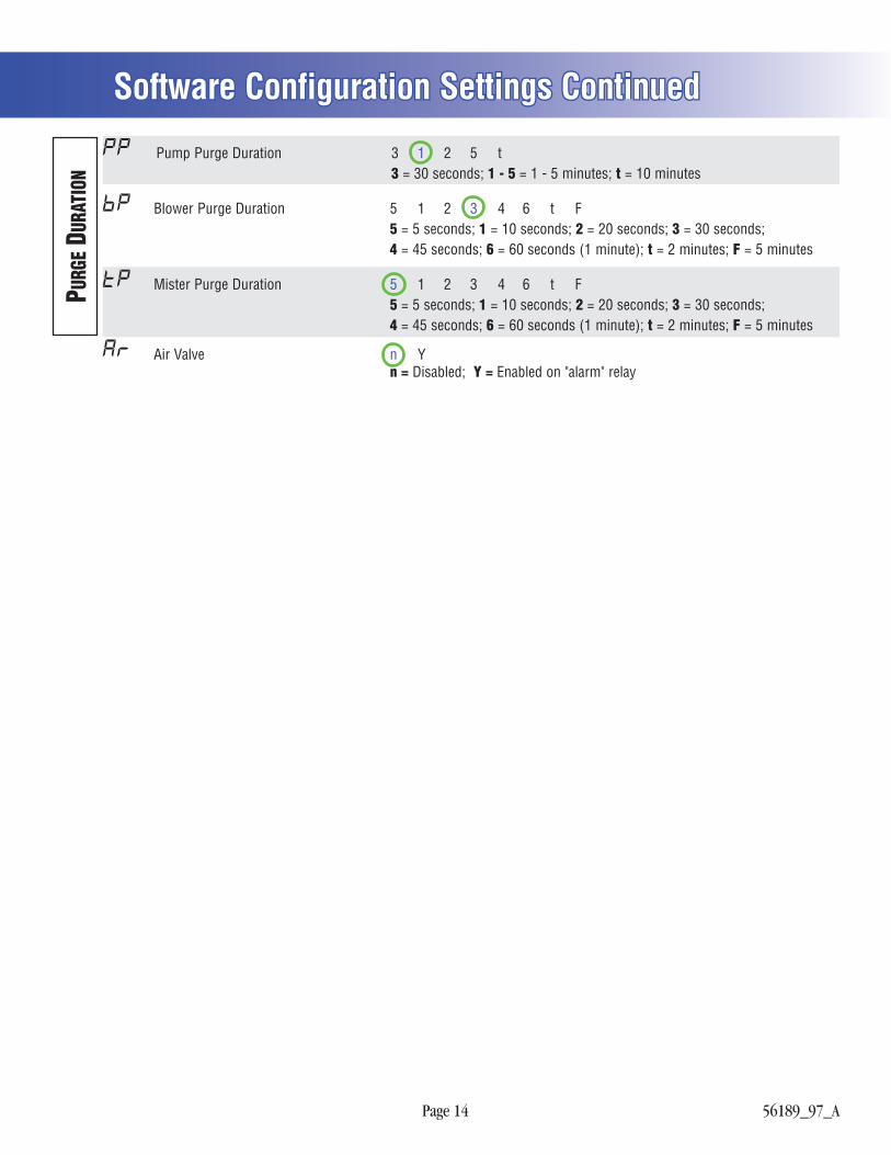
Pump Purge Duration 3 1 2 5 t 3 = 30 seconds; 1 - 5 = 1 - 5 minutes; t = 10 minutes
Blower Purge Duration 5 1 2 3 4 6 t F 5 = 5 seconds; 1 = 10 seconds; 2 = 20 seconds; 3 = 30 seconds; 4 = 45 seconds; 6 = 60 seconds (1 minute); t = 2 minutes; F = 5 minutes
Mister Purge Duration 5 1 2 3 4 6 t F 5 = 5 seconds; 1 = 10 seconds; 2 = 20 seconds; 3 = 30 seconds; 4 = 45 seconds; 6 = 60 seconds (1 minute); t = 2 minutes; F = 5 minutes
Air Valve n Y n = Disabled; Y = Enabled on "alarm" relay
Software Configuration Settings ContinuedSoftware Configuration Settings ContinuedPU
RGE D
URAT
ION
Page 15 56189_97_A
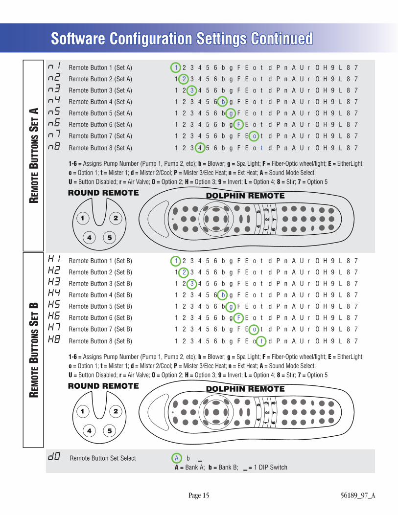
Remote Button 1 (Set A) 1 2 3 4 5 6 b g F E o t d P n A U r O H 9 L 8 7
Remote Button 2 (Set A) 1 2 3 4 5 6 b g F E o t d P n A U r O H 9 L 8 7
Remote Button 3 (Set A) 1 2 3 4 5 6 b g F E o t d P n A U r O H 9 L 8 7
Remote Button 4 (Set A) 1 2 3 4 5 6 b g F E o t d P n A U r O H 9 L 8 7
Remote Button 5 (Set A) 1 2 3 4 5 6 b g F E o t d P n A U r O H 9 L 8 7
Remote Button 6 (Set A) 1 2 3 4 5 6 b g F E o t d P n A U r O H 9 L 8 7
Remote Button 7 (Set A) 1 2 3 4 5 6 b g F E o t d P n A U r O H 9 L 8 7
Remote Button 8 (Set A) 1 2 3 4 5 6 b g F E o t d P n A U r O H 9 L 8 7
1-6 = Assigns Pump Number (Pump 1, Pump 2, etc); b = Blower; g = Spa Light; F = Fiber-Optic wheel/light; E = EitherLight; o = Option 1; t = Mister 1; d = Mister 2/Cool; P = Mister 3/Elec Heat; n = Ext Heat; A = Sound Mode Select; U = Button Disabled; r = Air Valve; O = Option 2; H = Option 3; 9 = Invert; L = Option 4; 8 = Stir; 7 = Option 5
1
1 2
54
45
23
67
8
DOLPHIN REMOTEROUND REMOTE
Remote Button 1 (Set B) 1 2 3 4 5 6 b g F E o t d P n A U r O H 9 L 8 7
Remote Button 2 (Set B) 1 2 3 4 5 6 b g F E o t d P n A U r O H 9 L 8 7
Remote Button 3 (Set B) 1 2 3 4 5 6 b g F E o t d P n A U r O H 9 L 8 7
Remote Button 4 (Set B) 1 2 3 4 5 6 b g F E o t d P n A U r O H 9 L 8 7
Remote Button 5 (Set B) 1 2 3 4 5 6 b g F E o t d P n A U r O H 9 L 8 7
Remote Button 6 (Set B) 1 2 3 4 5 6 b g F E o t d P n A U r O H 9 L 8 7
Remote Button 7 (Set B) 1 2 3 4 5 6 b g F E o t d P n A U r O H 9 L 8 7
Remote Button 8 (Set B) 1 2 3 4 5 6 b g F E o t d P n A U r O H 9 L 8 7
1-6 = Assigns Pump Number (Pump 1, Pump 2, etc); b = Blower; g = Spa Light; F = Fiber-Optic wheel/light; E = EitherLight; o = Option 1; t = Mister 1; d = Mister 2/Cool; P = Mister 3/Elec Heat; n = Ext Heat; A = Sound Mode Select; U = Button Disabled; r = Air Valve; O = Option 2; H = Option 3; 9 = Invert; L = Option 4; 8 = Stir; 7 = Option 5
1
1 2
54
45
23
67
8
DOLPHIN REMOTEROUND REMOTE
Remote Button Set Select A b _ A = Bank A; b = Bank B; _ = 1 DIP Switch
Software Configuration Settings ContinuedSoftware Configuration Settings ContinuedRE
MOT
E BU
TTON
S SE
T ARE
MOT
E BUT
TONS
SET
B
Page 16 56189_97_A
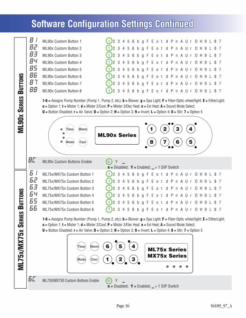
ML90x Custom Button 1 1 2 3 4 5 6 b g F E o t d P n A U r O H 9 L 8 7
ML90x Custom Button 2 1 2 3 4 5 6 b g F E o t d P n A U r O H 9 L 8 7
ML90x Custom Button 3 1 2 3 4 5 6 b g F E o t d P n A U r O H 9 L 8 7
ML90x Custom Button 4 1 2 3 4 5 6 b g F E o t d P n A U r O H 9 L 8 7
ML90x Custom Button 5 1 2 3 4 5 6 b g F E o t d P n A U r O H 9 L 8 7
ML90x Custom Button 6 1 2 3 4 5 6 b g F E o t d P n A U r O H 9 L 8 7
ML90x Custom Button 7 1 2 3 4 5 6 b g F E o t d P n A U r O H 9 L 8 7
ML90x Custom Button 8 1 2 3 4 5 6 b g F E o t d P n A U r O H 9 L 8 7
1-6 = Assigns Pump Number (Pump 1, Pump 2, etc); b = Blower; g = Spa Light; F = Fiber-Optic wheel/light; E = EitherLight; o = Option 1; t = Mister 1; d = Mister 2/Cool; P = Mister 3/Elec Heat; n = Ext Heat; A = Sound Mode Select; U = Button Disabled; r = Air Valve; O = Option 2; H = Option 3; 9 = Invert; L = Option 4; 8 = Stir; 7 = Option 5
ML90x Series1 2 3 4
8 7 6 5
Time WarmWarm
Modee Cool
ML90x Custom Buttons Enable n Y _ n = Disabled; Y = Enabled; _ = 1 DIP Switch
ML75x/MX75x Custom Button 1 1 2 3 4 5 6 b g F E o t d P n A U r O H 9 L 8 7
ML75x/MX75x Custom Button 2 1 2 3 4 5 6 b g F E o t d P n A U r O H 9 L 8 7
ML75x/MX75x Custom Button 3 1 2 3 4 5 6 b g F E o t d P n A U r O H 9 L 8 7
ML75x/MX75x Custom Button 4 1 2 3 4 5 6 b g F E o t d P n A U r O H 9 L 8 7
ML75x/MX75x Custom Button 5 1 2 3 4 5 6 b g F E o t d P n A U r O H 9 L 8 7
ML75x/MX75x Custom Button 6 1 2 3 4 5 6 b g F E o t d P n A U r O H 9 L 8 7
1-6 = Assigns Pump Number (Pump 1, Pump 2, etc); b = Blower; g = Spa Light; F = Fiber-Optic wheel/light; E = EitherLight; o = Option 1; t = Mister 1; d = Mister 2/Cool; P = Mister 3/Elec Heat; n = Ext Heat; A = Sound Mode Select; U = Button Disabled; r = Air Valve; O = Option 2; H = Option 3; 9 = Invert; L = Option 4; 8 = Stir; 7 = Option 5
ML75x SeriesMX75x Series
6 5 4
1 2 3
Time WarmmmWW
Modeee Cool
ML750/MX750 Custom Buttons Enable n Y _ n = Disabled; Y = Enabled; _ = 1 DIP Switch
Software Configuration Settings ContinuedSoftware Configuration Settings ContinuedM
L75X
/MX7
5X S
ERIE
S BUT
TONS
ML9
0X S
ERIE
S BUT
TONS
Page 17 56189_97_A
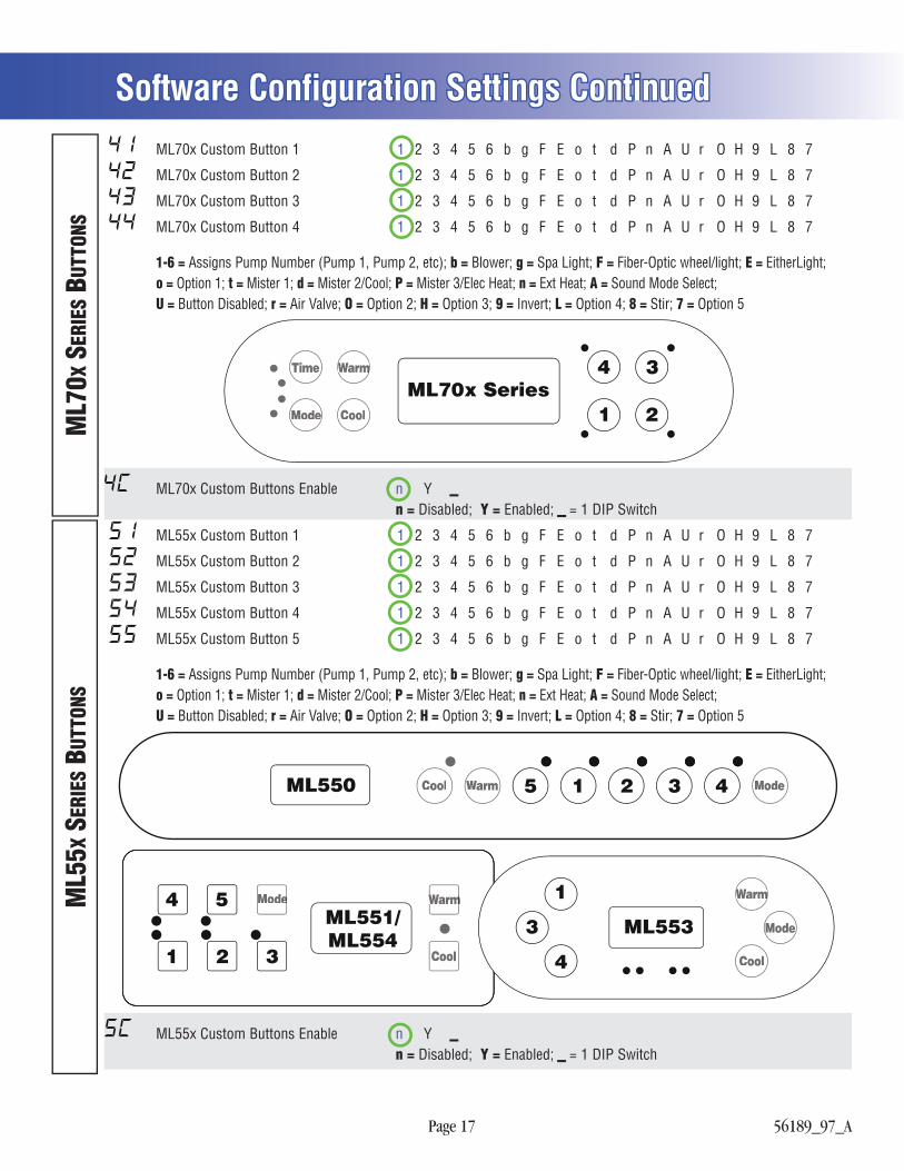
ML70x Custom Button 1 1 2 3 4 5 6 b g F E o t d P n A U r O H 9 L 8 7
ML70x Custom Button 2 1 2 3 4 5 6 b g F E o t d P n A U r O H 9 L 8 7
ML70x Custom Button 3 1 2 3 4 5 6 b g F E o t d P n A U r O H 9 L 8 7
ML70x Custom Button 4 1 2 3 4 5 6 b g F E o t d P n A U r O H 9 L 8 7
1-6 = Assigns Pump Number (Pump 1, Pump 2, etc); b = Blower; g = Spa Light; F = Fiber-Optic wheel/light; E = EitherLight; o = Option 1; t = Mister 1; d = Mister 2/Cool; P = Mister 3/Elec Heat; n = Ext Heat; A = Sound Mode Select; U = Button Disabled; r = Air Valve; O = Option 2; H = Option 3; 9 = Invert; L = Option 4; 8 = Stir; 7 = Option 5
ML70x Series4 3
1 2
Time WarmWarm
Modee Cool
ML70x Custom Buttons Enable n Y _ n = Disabled; Y = Enabled; _ = 1 DIP Switch
ML55x Custom Button 1 1 2 3 4 5 6 b g F E o t d P n A U r O H 9 L 8 7
ML55x Custom Button 2 1 2 3 4 5 6 b g F E o t d P n A U r O H 9 L 8 7
ML55x Custom Button 3 1 2 3 4 5 6 b g F E o t d P n A U r O H 9 L 8 7
ML55x Custom Button 4 1 2 3 4 5 6 b g F E o t d P n A U r O H 9 L 8 7
ML55x Custom Button 5 1 2 3 4 5 6 b g F E o t d P n A U r O H 9 L 8 7
1-6 = Assigns Pump Number (Pump 1, Pump 2, etc); b = Blower; g = Spa Light; F = Fiber-Optic wheel/light; E = EitherLight; o = Option 1; t = Mister 1; d = Mister 2/Cool; P = Mister 3/Elec Heat; n = Ext Heat; A = Sound Mode Select; U = Button Disabled; r = Air Valve; O = Option 2; H = Option 3; 9 = Invert; L = Option 4; 8 = Stir; 7 = Option 5
ML550
ML551/ML554
1
1 2 3
5 2 3 4
4 5ML553
1
3
4
Cool
CoolCool
Warm
WarmWarmWarmWarm
Mode
Modee
Modee
ML55x Custom Buttons Enable n Y _ n = Disabled; Y = Enabled; _ = 1 DIP Switch
Software Configuration Settings ContinuedSoftware Configuration Settings ContinuedM
L70X
SER
IES B
UTTO
NSM
L55X
SER
IES B
UTTO
NS
Page 18 56189_97_A
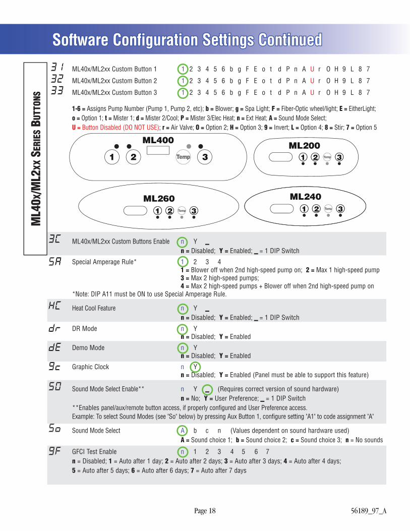
ML40x/ML2xx Custom Button 1 1 2 3 4 5 6 b g F E o t d P n A U r O H 9 L 8 7
ML40x/ML2xx Custom Button 2 1 2 3 4 5 6 b g F E o t d P n A U r O H 9 L 8 7
ML40x/ML2xx Custom Button 3 1 2 3 4 5 6 b g F E o t d P n A U r O H 9 L 8 7
1-6 = Assigns Pump Number (Pump 1, Pump 2, etc); b = Blower; g = Spa Light; F = Fiber-Optic wheel/light; E = EitherLight; o = Option 1; t = Mister 1; d = Mister 2/Cool; P = Mister 3/Elec Heat; n = Ext Heat; A = Sound Mode Select; U = Button Disabled (DO NOT USE); r = Air Valve; O = Option 2; H = Option 3; 9 = Invert; L = Option 4; 8 = Stir; 7 = Option 5
ML400
1 2 3ML200
321
ML260321
ML240321
TempTemp
TempTempp TempTemp
TempTemp
ML40x/ML2xx Custom Buttons Enable n Y _ n = Disabled; Y = Enabled; _ = 1 DIP Switch
Special Amperage Rule* 1 2 3 4 1 = Blower off when 2nd high-speed pump on; 2 = Max 1 high-speed pump 3 = Max 2 high-speed pumps; 4 = Max 2 high-speed pumps + Blower off when 2nd high-speed pump on *Note: DIP A11 must be ON to use Special Amperage Rule.
Heat Cool Feature n Y _ n = Disabled; Y = Enabled; _ = 1 DIP Switch
DR Mode n Y n = Disabled; Y = Enabled
Demo Mode n Y n = Disabled; Y = Enabled
Graphic Clock n Y n = Disabled; Y = Enabled (Panel must be able to support this feature)
Sound Mode Select Enable** n Y _ (Requires correct version of sound hardware) n = No; Y = User Preference; _ = 1 DIP Switch **Enables panel/aux/remote button access, if properly configured and User Preference access. Example: To select Sound Modes (see "So" below) by pressing Aux Button 1, configure setting "A1" to code assignment "A"
Sound Mode Select A b c n (Values dependent on sound hardware used) A = Sound choice 1; b = Sound choice 2; c = Sound choice 3; n = No sounds
GFCI Test Enable n 1 2 3 4 5 6 7 n = Disabled; 1 = Auto after 1 day; 2 = Auto after 2 days; 3 = Auto after 3 days; 4 = Auto after 4 days; 5 = Auto after 5 days; 6 = Auto after 6 days; 7 = Auto after 7 days
Software Configuration Settings ContinuedSoftware Configuration Settings ContinuedM
L40X
/ML2
XX S
ERIE
S BUT
TONS
Page 19 56189_97_A
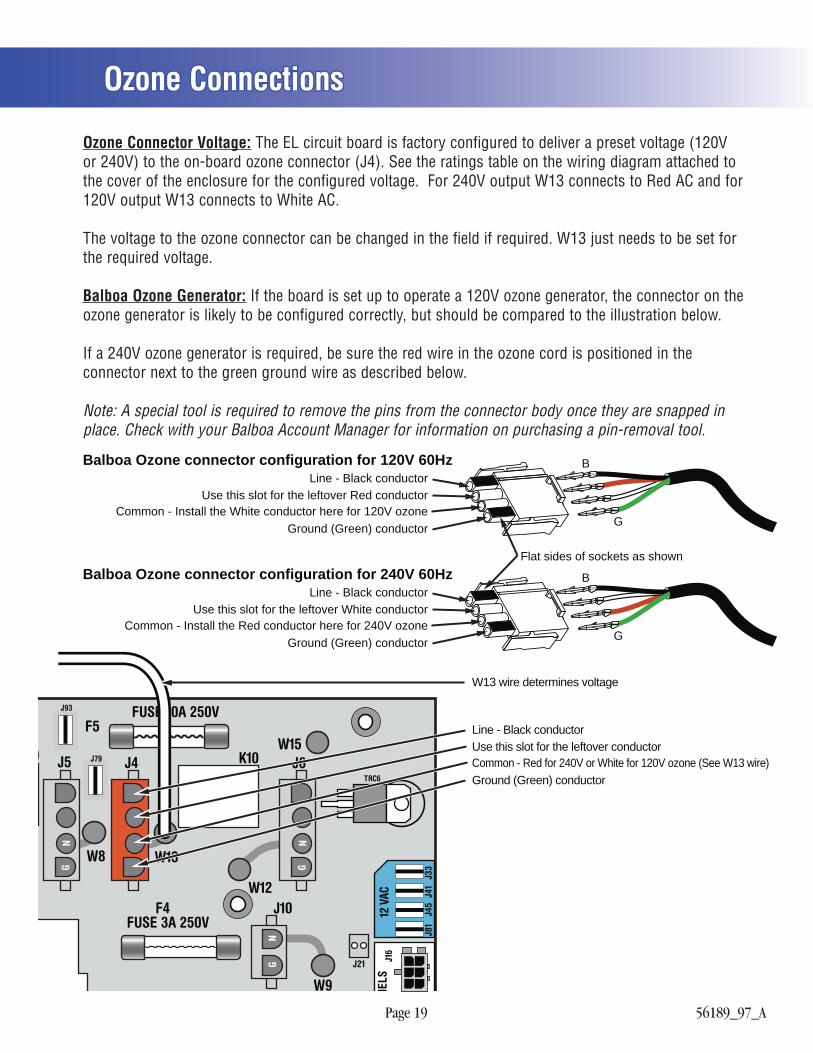
Ozone ConnectionsOzone Connections
9 K10
GN
GN
J4J5 J6
W8
W12
W9
W13
W15
J21
TRC6
F5FUSE 10A 250VJ93
J79
FUSE 3A 250VF4
NG
J10
J81
J45
J41
J33
NELS
12 V
ACJ1
6
Use this slot for the leftover Red conductorLine - Black conductor
Balboa Ozone connector configuration for 120V 60Hz
Ground (Green) conductor
Flat sides of sockets as shown
Common - Install the White conductor here for 120V ozone
Use this slot for the leftover White conductorLine - Black conductor
Balboa Ozone connector configuration for 240V 60Hz
Ground (Green) conductorCommon - Install the Red conductor here for 240V ozone
B
G
B
G
Use this slot for the leftover conductorLine - Black conductor
Ground (Green) conductorCommon - Red for 240V or White for 120V ozone (See W13 wire)
W13 wire determines voltage
Ozone Connector Voltage: The EL circuit board is factory configured to deliver a preset voltage (120V or 240V) to the on-board ozone connector (J4). See the ratings table on the wiring diagram attached to the cover of the enclosure for the configured voltage. For 240V output W13 connects to Red AC and for 120V output W13 connects to White AC.
The voltage to the ozone connector can be changed in the field if required. W13 just needs to be set for the required voltage.
Balboa Ozone Generator: If the board is set up to operate a 120V ozone generator, the connector on the ozone generator is likely to be configured correctly, but should be compared to the illustration below.
If a 240V ozone generator is required, be sure the red wire in the ozone cord is positioned in the connector next to the green ground wire as described below.
Note: A special tool is required to remove the pins from the connector body once they are snapped in place. Check with your Balboa Account Manager for information on purchasing a pin-removal tool.
Page 20 56189_97_A
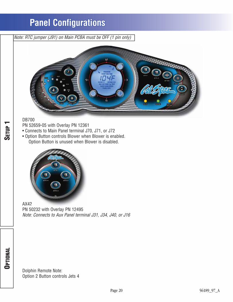
Panel ConfigurationsPanel Configurations
SETU
P 1
OPTI
ONAL
Note: RTC jumper (J91) on Main PCBA must be OFF (1 pin only)
DB700PN 52659-05 with Overlay PN 12361• Connects to Main Panel terminal J70, J71, or J72• Option Button controls Blower when Blower is enabled. Option Button is unused when Blower is disabled.
AX42PN 50232 with Overlay PN 12495Note: Connects to Aux Panel terminal J31, J34, J40, or J16
Dolphin Remote Note:Option 2 Button controls Jets 4
242