Embed Size (px)
Citation preview

CS420-L and CS425-L Druck’sModels PDCR 1830 and 1230
Pressure TransducersRevision: 12/07
C o p y r i g h t © 2 0 0 0 - 2 0 0 7C a m p b e l l S c i e n t i f i c , I n c .

The CS420-L and CS425-L Pressure Transducers are manufactured by Druck Incorporated. Druck’s conditions of sale and return policy apply to these items. Products may not be returned without prior authorization. To obtain an RMA number contact Druck, Inc., phone (203) 746-0400. NOTE: if the product has been exposed to hazardous media, it must be fully decontaminated and neutralized prior to return to Druck.

CS420-L/CS425-L (Druck PDCR Series) Table of Contents PDF viewers note: These page numbers refer to the printed version of this document. Use the Adobe Acrobat® bookmarks tab for links to specific sections.
1. General Information.....................................................1
2. Specifications ..............................................................1
3. Installation....................................................................2 3.1 Vent Tubes................................................................................................2 3.2 Dislodging Bubbles ..................................................................................2 3.3 Transient Protection..................................................................................2 3.4 Temperature Fluctuations .........................................................................2
4. Datalogger - Sensor Connections ..............................2 4.1 Six-Wire Configuration ............................................................................3 4.2 Four-Wire Configuration..........................................................................3
5. Programming ...............................................................3 5.1 Using Short Cut ........................................................................................3 5.2 Using CRBasic, Edlog, or the Keyboard/Display.....................................4
5.2.1 Calculating the Multiplier ...............................................................4 5.2.2 Calculating the Offset .....................................................................5
5.3 Fine Tuning the Excitation and Input Range ............................................5 5.4 Increasing the Resolution .........................................................................6
6. CRBasic Program Examples ......................................7 6.1 Wiring for the Program Examples ............................................................7
6.1.1 BrFull Instruction (4-Wire Full Bridge Measurement) ...................7 6.1.2 BrFull6W Instruction (6-Wire Full Bridge Measurement) .............7
6.2 CR800, CR850, and CR1000 Programs ...................................................8 6.2.1 BrFull Instruction (4-Wire Full Bridge Measurement) ...................8 6.2.2 BrFull6W Instruction (6-Wire Full Bridge Measurement) .............8
6.3 CR3000 Programs.....................................................................................9 6.3.1 BrFull Instruction (4-Wire Full Bridge Measurement) ...................9 6.3.2 BrFull6W Instruction (6-Wire Full Bridge Measurement) .............9
6.4 CR5000 Programs...................................................................................10 6.4.1 BrFull Instruction (4-Wire Full Bridge Measurement) .................10 6.4.2 BrFull6W Instruction (6-Wire Full Bridge Measurement) ...........10
i

CS420-L/CS425-L Table of Contents
ii
7. Edlog Program Examples .........................................11 7.1 CR10(X), CR510, and CR500 Examples............................................... 11
7.1.1 Instruction 6 (4-Wire Full Bridge Measurement)......................... 11 7.1.2 Instruction 9 (6-Wire Full Bridge w/Excitation).......................... 12
7.2 CR23X and 21X Examples .................................................................... 13 7.2.1 Instruction 6 (4-Wire Full Bridge Measurement)......................... 13 7.2.2 Instruction 9 (6-Wire Full Bridge w/Excitation).......................... 14
8. Using Multiplexers .....................................................15 8.1 Examples................................................................................................ 15
8.1.1 Wiring For One Druck Multiplexer/Datalogger........................... 15 8.1.2 Multiplexer Connection................................................................ 16 8.1.3 CRBasic Multiplexer Examples ................................................... 16 8.1.4 Edlog Example ............................................................................. 19
9. Maintenance ...............................................................20 9.1 Every Visit, At Least Monthly............................................................... 20 9.2 Every Three Months .............................................................................. 21 9.3 Every Two to Three Years or on a Rotating Schedule........................... 21
10. Troubleshooting.......................................................21
Table 1. Conversion Factors .................................................................................... 4

CS420-L and CS425-L Pressure Transducers This manual describes using the CS420-L and CS425-L pressure transducers with Campbell Scientific’s CR800, CR850, CR1000, CR3000, CR5000, CR10(X), CR23X, CR510, CR500, and 21X dataloggers. Information provided in the manual includes datalogger-to-sensor connection, datalogger programming, use of multiplexers in the system, and maintenance requirements.
1. General Information The CS420-L is Druck’s model PDCR 1830-8388; the CS425-L is model PDCR 1230-8388. Druck PDCR 1230 and 1830 pressure transducers are used for surface and ground water level measurement. The CS425-L sensor can be ordered in pressure ranges between 5 and 900 psi and has an accuracy of ±0.25% of the Full Scale Range (FSR); the CS420-L can be ordered in pressure ranges between 1 and 900 psi and has an accuracy of ±0.1% FSR. Further information on sensor construction can be obtained from Druck’s 1230 or 1830 Pressure Transducer brochures.
2. Specifications Overpressure 8x for 1 and 2.5 psig range 6x for 5 psig range 4x for 10 psig and above ranges
Excitation Voltage 10 Volts at 5 mA maximum
Output Voltage 25mV for 1 psig range 50mV for 2.5 and 5 psig ranges 100mV for ranges 10 psi and above Output is ratiometric to supply
Combined non-linearity, hysteresis and repeatability ±0.1% of Full Scale, Best Fit Straight Line for CS420-L ±0.25% of Full Scale, Best Fit Straight Line for CS425-L
Operating Temperature Range -20ºC to +60ºC
Compensated Temperature Range -2ºC to +30ºC
Long Term Stability Typically ±0.1 mV/annum
1

CS420-L and CS425-L Pressure Transducers
3. Installation 3.1 Vent Tubes
A vent tube incorporated in the cable vents the sensor diaphragm to the atmosphere. This eliminates the need to compensate the water level measurement for changes in barometric pressure.
To prevent water vapor from entering the inner cavity of the sensor, the transducers are typically shipped with the vent tubes sealed. Before operation, visually confirm the vent tube is open. The vent tube opening must terminate inside a desiccated enclosure or a Campbell Scientific DES2 desiccant case.
The desiccant must be changed regularly. NOTE
3.2 Dislodging Bubbles While submersing the sensor, air bubbles may become trapped between the pressure plate and the water surface, causing small offset errors until the bubbles dissolve. Dislodge these bubbles by gently shaking the pressure transducer while it is under water.
Do not hit the sensor against the well casing or other solid surface while dislodging the bubbles, because the diaphragm could be damaged.
CAUTION
3.3 Transient Protection Campbell Scientific recommends transient surge protection for sensors installed in lightning prone areas. No lightning protection is capable of withstanding a direct hit, but surge protectors afford a degree of protection for near misses. Surge protection can be provided by Campbell Scientific’s SVP48 Surge Voltage Protector. When an electrical surge occurs, the surge protectors involved may need to be replaced.
3.4 Temperature Fluctuations Temperature fluctuations can be minimized by using a minimum cable burial depth of six inches and a sensor submersion depth of one foot. Also, if your site may experience extreme temperature fluctuations, the transducer must be measured using the six-wire configuration.
4. Datalogger - Sensor Connections The transducers are configured for a six-wire measurement. If using short cable lengths (< 100 feet) and extreme temperature fluctuations are not likely, a four-wire measurement can also be made reliably. The six-wire measurement is more accurate and the only advantage of the four-wire measurement is it requires fewer analog channels. The four-wire configuration
2

CS420-L and CS425-L Pressure Transducers
does not use the orange and black wires and the ends of each of these wires should be taped to prevent shorting.
4.1 Six-Wire Configuration Datalogger CS420-L/CS425-L
Excitation Red (Supply Positive) AG (Analog Ground) White (Supply Negative) HI (Analog) Orange (Excitation Monitor +) LO (Analog) Black (Excitation Monitor -) HI (Analog) Yellow (Signal Output +) LO (Analog) Blue (Signal Output -) G (Ground) Clear (Shield)
4.2 Four-Wire Configuration Datalogger CS420-L/CS425-L
Excitation Red (Supply Positive) AG (Analog Ground) White (Supply Negative) HI (Analog) Yellow (Signal Output +) LO (Analog) Blue (Signal Output -) G (Ground) Clear (Shield)
The datalogger must be properly grounded. This reduces electromagnetic noise and chances of damage from lightning.
NOTE
5. Programming Use Short Cut, CRBasic, Edlog, or the datalogger Keyboard/Display to program the datalogger to read these sensors. All programming methods require the sensitivity value which is listed in the calibration certificate. A calibration certificate should accompany every sensor received from Druck. It is specific to the individual sensor; verify that the certificate and the sensor have the same serial number, and retain the certificate for your records.
5.1 Using Short Cut Short Cut is the easiest and typically the preferred method for programming the datalogger. Short Cut will ask for the sensitivity which is listed on the calibration certificate. From this value, Short Cut will calculate the multiplier.
Choose either the “Manual Offset” or “Automatic Offset” module to adjust the transducer reading to the current water level reading.
Short Cut stores the Druck level data in the high resolution format. Short Cut also generates a wiring diagram that shows how to connect the Druck transducer to your datalogger.
3

CS420-L and CS425-L Pressure Transducers
The sections that immediately follow are for CRBasic, Edlog, and Keyboard/Display users. Short Cut users can jump ahead to the Maintenance section (page 21).
NOTE
5.2 Using CRBasic, Edlog, or the Keyboard/Display For dataloggers programmed with CRBasic use the BrFull instruction to make a four-wire measurement and BrFull6W to make a six wired measurement. For Edlog dataloggers use Instruction 6–Full Bridge Measurement to make a four-wire measurement or Instruction 9–Full Bridge with Measured Excitation to make a six-wire measurement. These instructions require a unique multiplier and offset to be calculated for each sensor. Your datalogger manual has a detailed explanation of these instructions and there is extensive help in the CRBasic editor. Also see the programming examples that start on page 7 of this document.
5.2.1 Calculating the Multiplier The value for the sensitivity is listed on each transducer’s calibration certificate. It will be shown in units of either mV/V/psig or mV. Based on the units of sensitivity, choose one of the following equations to calculate the multiplier (M):
(V) Voltagey (mV)/Supply Sensitivit
(psig) Range =Mor
)(mV/V/psigy Sensitivit
1=M
After calculating M, use the conversion factor listed in Table 1 to convert the value to the desired engineering units.
TABLE 1. Conversion Factors
To change To Multiply by
mb ft of water 0.0334883 psig ft of water 2.306725 mb meters of water 0.010207 psig meters of water 0.70309
Example:
When Druck calibration certificate lists the following values for a sensor:
sensitivity = 0.98 (mV/V)/psig
The multiplier is:
M = 1/(0.98 (mV/V)/psig) = 1.02 psig/(mV/V)
If the desired engineering units are feet of water, the multiplier becomes:
(1.02 psig/(mV/V))*(2.306725 ft of water/psig)= 2.3529 ft of water/(mV/V)
4

CS420-L and CS425-L Pressure Transducers
5.2.2 Calculating the Offset The offset is calculated with the following procedure:
1. Program the datalogger using the calculated multiplier and an offset of 0 in either a 6-wire full bridge instruction (BrFull6W in CRBasic or Instruction 9 in Edlog) or a 4-wire full bridge instruction (BrFull in CRBasic or Instruction 6 in Edlog). Set the execution interval to one second.
2. Install the Druck transducer and a staff gauge at the same location or install the Druck transducer at a known depth.
3. If applicable, measure the depth using the staff gauge.
4. Use a keyboard display or PC to view the depth reading (refer to your datalogger manual for information about viewing real-time data).
5. Subtract the value displayed on the keyboard display or PC from the known depth or the staff gauge’s reading.
Always make sure your multiplier and offset are in the same units (e.g., feet, inches).
NOTE
When using Edlog, large offsets may cause truncation of Final Storage values resulting in fewer significant digits. If this is a problem, do the offset correction after the data is collected or use Instruction 78 to store the data in the high resolution format.
Example:
A staff gauge and a Druck transducer are installed at the same location. If the staff gauge reads 10.07 feet and the value displayed on your keyboard display or PC is 10.56 feet, the offset for the Full Bridge Instruction is:
Offset = 10.07 ft - 10.56 ft = -0.49 ft
Enter -0.49 for the offset parameter in the Full Bridge Instruction.
5.3 Fine Tuning the Excitation and Input Range Choose a datalogger input range that is larger than the output from the sensor. The voltage ranges and codes are listed in your datalogger manual, the CRBasic help, or the Edlog help.
Typically 2500 mV excitation is used with CR800, CR850, CR1000, CR10(X), CR510, or CR500 dataloggers; 5000 mV is used with CR3000, CR5000, CR23X, and 21X dataloggers. To calculate the sensor output when a specific excitation is applied, use one of the following equations:
output mV = (pressure range psig) (sensitivity (mV/V)(psig) (excitation V)
∗∗
5
CS420-L and CS425-L Pressure Transducers
or
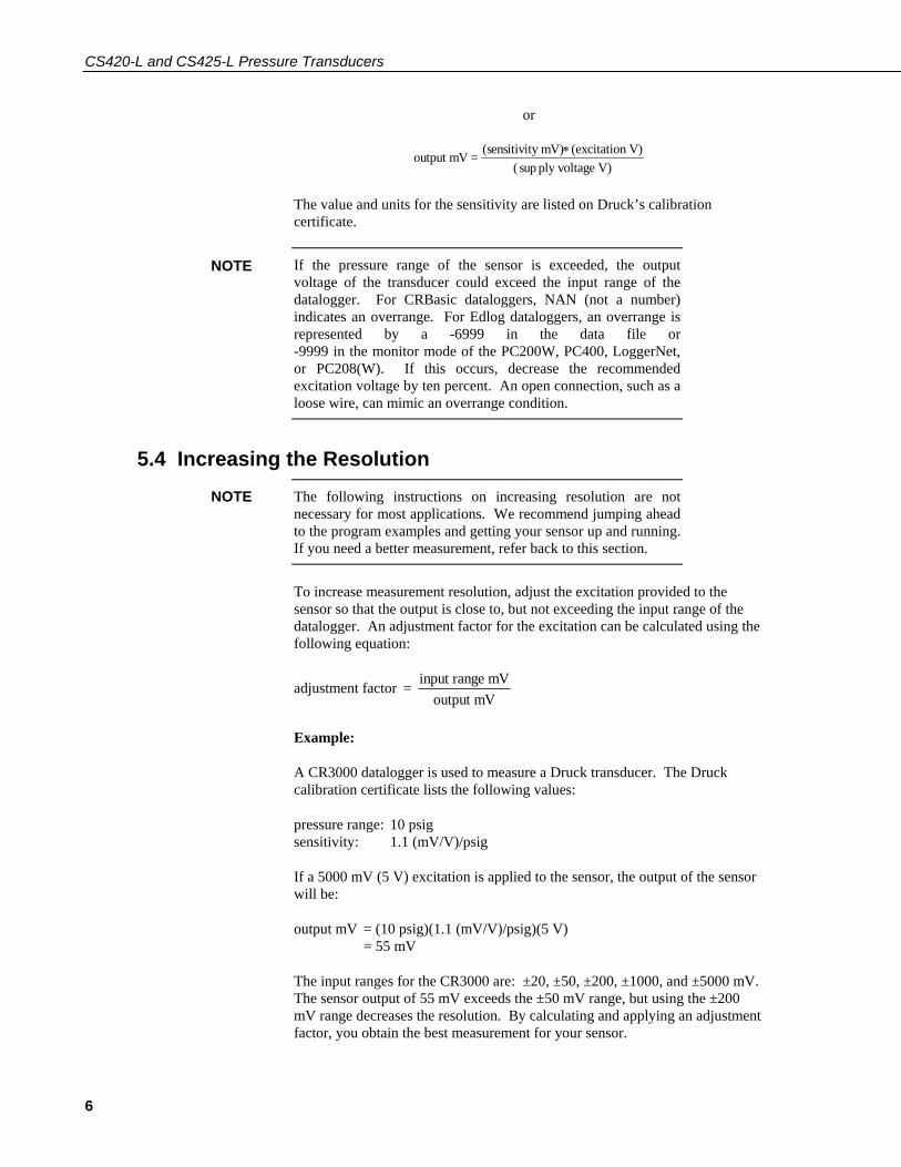
output mV = (sensitivity mV) (excitation V)( ply voltage V)
∗sup
The value and units for the sensitivity are listed on Druck’s calibration certificate.
If the pressure range of the sensor is exceeded, the output voltage of the transducer could exceed the input range of the datalogger. For CRBasic dataloggers, NAN (not a number) indicates an overrange. For Edlog dataloggers, an overrange is represented by a -6999 in the data file or -9999 in the monitor mode of the PC200W, PC400, LoggerNet, or PC208(W). If this occurs, decrease the recommended excitation voltage by ten percent. An open connection, such as a loose wire, can mimic an overrange condition.
NOTE
5.4 Increasing the Resolution The following instructions on increasing resolution are not necessary for most applications. We recommend jumping ahead to the program examples and getting your sensor up and running. If you need a better measurement, refer back to this section.
NOTE
To increase measurement resolution, adjust the excitation provided to the sensor so that the output is close to, but not exceeding the input range of the datalogger. An adjustment factor for the excitation can be calculated using the following equation:
adjustment factor = input range mVoutput mV
Example:
A CR3000 datalogger is used to measure a Druck transducer. The Druck calibration certificate lists the following values:
pressure range: 10 psig sensitivity: 1.1 (mV/V)/psig
If a 5000 mV (5 V) excitation is applied to the sensor, the output of the sensor will be:
output mV = (10 psig)(1.1 (mV/V)/psig)(5 V) = 55 mV
The input ranges for the CR3000 are: ±20, ±50, ±200, ±1000, and ±5000 mV. The sensor output of 55 mV exceeds the ±50 mV range, but using the ±200 mV range decreases the resolution. By calculating and applying an adjustment factor, you obtain the best measurement for your sensor.
6

CS420-L and CS425-L Pressure Transducers
adjustment factor = input rangeoutput
= 50 mV55 mV
= .909
The excitation adjusted to output 50 mV is:
adjusted excitation = (original excitation)*(calculated adjustment factor) = (5000 mV)*(.909) = 4545 mV
Use 4545 mV to excite the sensor instead of 5000 mV within either the BrFull or BrFull6W instruction.
6. CRBasic Program Examples 6.1 Wiring for the Program Examples
6.1.1 BrFull Instruction (4-Wire Full Bridge Measurement) Datalogger CS420-L/CS425-L
Excitation E1 Red (Supply +) Input H1 Yellow (Output +) Input L1 Blue (Output -) Analog Ground AG White (Supply -) G Clear (Shield)
The orange and black wires are not used and the ends of these wires should be taped to prevent shorting.
6.1.2 BrFull6W Instruction (6-Wire Full Bridge Measurement) Datalogger CS420-L/CS425-L
Excitation E1 Red (Supply +) Input H1 Orange (Monitor +) Input L1 Black (Monitor -) Input H2 Yellow (Output +) Input L2 Blue (Output -) An. Ground AG White (Supply -) G Clear (Shield)
7

CS420-L and CS425-L Pressure Transducers
6.2 CR800, CR850, and CR1000 Programs
6.2.1 BrFull Instruction (4-Wire Full Bridge Measurement) 'CR1000, CR800, CR850 '4wire configuration Public Depth_Ft DataTable (WtrData,1,-1) DataInterval (0,15,Min,10) Sample (1,Depth_Ft,FP2) EndTable BeginProg Scan (15,Min,0,0) BrFull (Depth_Ft,1,mV2500,1,Vx1,1,2500,True ,True ,0,250,2.3529,-0.49) CallTable WtrData NextScan EndProg
6.2.2 BrFull6W Instruction (6-Wire Full Bridge Measurement) 'CR1000, CR800, CR850 '6wire configuration Public Depth_Ft DataTable (WtrData,1,-1) DataInterval (0,15,Min,10) Sample (1,Depth_Ft,FP2) EndTable BeginProg Scan (15,Min,0,0) BrFull6W (Depth_Ft,1,mV2500,mV25,1,Vx1,1,2500,True ,True ,0,250,2.3529,-0.49) CallTable WtrData NextScan EndProg
8
CS420-L and CS425-L Pressure Transducers
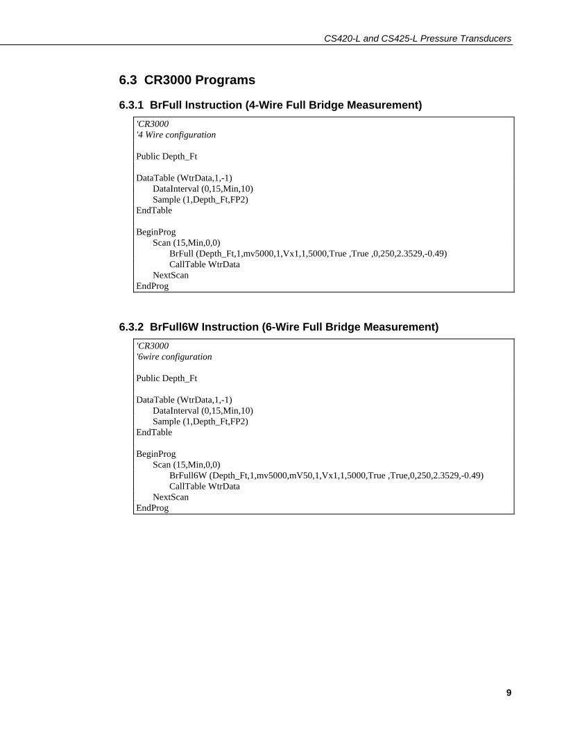
6.3 CR3000 Programs
6.3.1 BrFull Instruction (4-Wire Full Bridge Measurement) 'CR3000 '4 Wire configuration Public Depth_Ft DataTable (WtrData,1,-1) DataInterval (0,15,Min,10) Sample (1,Depth_Ft,FP2) EndTable BeginProg Scan (15,Min,0,0) BrFull (Depth_Ft,1,mv5000,1,Vx1,1,5000,True ,True ,0,250,2.3529,-0.49) CallTable WtrData NextScan EndProg
6.3.2 BrFull6W Instruction (6-Wire Full Bridge Measurement) 'CR3000 '6wire configuration Public Depth_Ft DataTable (WtrData,1,-1) DataInterval (0,15,Min,10) Sample (1,Depth_Ft,FP2) EndTable BeginProg Scan (15,Min,0,0) BrFull6W (Depth_Ft,1,mv5000,mV50,1,Vx1,1,5000,True ,True,0,250,2.3529,-0.49) CallTable WtrData NextScan EndProg
9

CS420-L and CS425-L Pressure Transducers
6.4 CR5000 Programs
6.4.1 BrFull Instruction (4-Wire Full Bridge Measurement) 'CR5000 '4 Wire configuration Public Depth_Ft DataTable (WtrData,1,-1) DataInterval (0,15,Min,10) Sample (1,Depth_Ft,FP2) EndTable BeginProg Scan (15,Min,0,0) BrFull (Depth_Ft,1,mV20,1,Vx1,1,5000,True ,True,0,250,2.3529,-0.49) CallTable WtrData NextScan EndProg
6.4.2 BrFull6W Instruction (6-Wire Full Bridge Measurement) 'CR5000 '6 wire configuration Public Depth_Ft DataTable (WtrData,1,-1) DataInterval (0,15,Min,10) Sample (1,Depth_Ft,FP2) EndTable BeginProg Scan (15,Min,0,0) BrFull6W (Depth_Ft,1,mv5000,mV50,1,Vx1,1,5000,True ,True,0,250,2.3529,-0.49) CallTable WtrData NextScan EndProg
10

CS420-L and CS425-L Pressure Transducers
7. Edlog Program Examples 7.1 CR10(X), CR510, and CR500 Examples
7.1.1 Instruction 6 (4-Wire Full Bridge Measurement)
7.1.1.1 Wiring
Datalogger CS420-L/CS425-L
Excitation E1 Red (Supply +) Input H1 Yellow (Output +) Input L1 Blue (Output -) An. Ground AG White (Supply -) G Clear (Shield)
The orange and black wires are not used and the ends of these wires should be taped to prevent shorting.
7.1.1.2 Edlog Program
; Measure one 4-wire DRUCK Sensor. * Table 1 Program 01: 5 Execution Interval (seconds) 1: Full Bridge (P6) 1: 1 Reps 2: 3 25 mV slow range 3: 1 DIFF channel 4: 1 Excite all reps w/Exchan 1 5: 2500 mV excitation 6: 1 Loc [DEPTH_FT] 7: 2.3529 Mult 8: -0.49 Offset ; Every 60 minutes output the array ID, time, ; and average water depth in feet 2: If Time Is (P92) 1: 0 Minutes (seconds --) into 2: 60 Interval (same units as above) 3: 10 Set output flag high (Flag 0) 3: Real Time (P77) 1: 110 Day, Hour/Minute (midnight = 0000) 4: Average (P71) 1: 1 Reps 2: 1 Loc [DEPTH_FT]
11

CS420-L and CS425-L Pressure Transducers
7.1.2 Instruction 9 (6-Wire Full Bridge w/Excitation)
7.1.2.1 Wiring
Datalogger CS420-L/CS425-L
Excitation E1 Red (Supply +) Input H1 Orange (Monitor +) Input L1 Black (Monitor -) Input H2 Yellow (Output +) Input L2 Blue (Output -) An. Ground AG White (Supply -) G Clear (Shield)
7.1.2.2 Edlog Program
; Measure one 6-wire DRUCK Sensor. * Table 1 Programs 01: 5 Sec. Execution Interval 1: Full Bridge w/mV Excit (P9) 1: 1 Reps 2: 5 2500 mV Slow Ex Range 3: 3 25 mV Slow Br Range 4: 1 DIFF Channel 5: 1 Excite all reps w/Exchan 1 6: 2500 mV Excitation 7: 1 Loc [DEPTH_FT] 8: 2.3529 Mult 9: -0.49 Offset ; Every 60 minutes output the array ID, time, ; and average water depth in feet 2: If time is (P92) 1: 0000 Minutes (seconds --) into a 2: 60 Interval (same units as above) 3: 10 Set output flag high (Flag 0) 3: Real Time (P77) 1: 110 Day, Hour/Minute (midnight = 0000) 4: Average (P71) 1: 1 Reps 2: 1 Loc [DEPTH_FT]
12

CS420-L and CS425-L Pressure Transducers
7.2 CR23X and 21X Examples
7.2.1 Instruction 6 (4-Wire Full Bridge Measurement)
7.2.1.1 Wiring
Datalogger CS420-L/CS425-L
Excitation E1 Red (Supply +) Input H1 Yellow (Output +) Input L1 Blue (Output -) G White (Supply -) G Clear (Shield)
The orange and black wires are not used and the ends of these wires should be taped to prevent shorting.
7.2.1.2 Edlog Program
; Measure one 4-wire DRUCK Sensor. * Table 1 Program 01: 5 Execution Interval (seconds) 1: Full Bridge (P6) 1: 1 Reps 2: 22* 50 mV, 60 Hz Rejection, Slow Range 3: 1 DIFF Channel 4: 1 Excite all reps w/Exchan 1 5: 5000 mV Excitation 6: 1 Loc [DEPTH_FT] 7: 2.3529 Mult 8: -0.49 Offset *for 21X use Range Code 3 ; Every 60 minutes output the array ID, time, ; and average water depth in feet. 2: If time is (P92) 1: 0000 Minutes into a 2: 60 Minute Interval 3: 10 Set output flag high 3: Real Time (P77) 1: 110 Day, Hour/Minute (midnight = 0000) 4: Average (P71) 1: 1 Reps 2: 1 Loc [DEPTH_FT]
13

CS420-L and CS425-L Pressure Transducers
7.2.2 Instruction 9 (6-Wire Full Bridge w/Excitation)
7.2.2.1 Wiring
Datalogger CS420-L/CS425-L
Excitation E1 Red (Supply +) Input H1 Orange (Monitor +) Input L1 Black (Monitor -) Input H2 Yellow (Output +) Input L2 Blue (Output -) G White (Supply -) G Clear (Shield)
7.2.2.2 Edlog Program
; Measure one 6-wire DRUCK Sensor. * Table 1 Program 01: 5 Execution Interval (seconds) 1: Full Bridge w/mV Excit (P9) 1: 1 Reps 2 25* 5000 mV, 60Hz Rejection, slow Ex Range 3: 22** 50 mV, 60 Hz Rejection, Slow Br Range 4: 1 DIFF Channel 5: 1 Excite all reps w/Exchan 1 6: 5000 mV Excitation 7: 1 Loc [DEPTH_FT] 8: 2.3529 Mult 9: -0.49 Offset *For 21X use Range Code 5 **For 21X use Range Code 3 ; Every 60 minutes output the array ID, time, ; and average water depth in feet 2: If time is (P92) 1: 0000 Minutes into a 2: 60 Minute Interval 3: 10 Set output flag high 3: Real Time (P77) 1: 110 Day, Hour/Minute (midnight = 0000) 4: Average (P71) 1: 1 Reps 2 1 Loc [DEPTH_FT]
14

CS420-L and CS425-L Pressure Transducers
8. Using Multiplexers Multiplexers increase the number of transducers a single datalogger can measure.
The CR500 and CR510 dataloggers do not support the use of multiplexers.
NOTE
8.1 Examples The dataloggers in the examples measure four Druck pressure transducers that are connected to an AM16/32A multiplexer. Excitation is supplied to the sensor from the datalogger wiring panel. In the examples, excitation voltage and ground connection to the sensor bypass the multiplexer and are applied directly from the datalogger to the sensor.
This configuration allows up to 16 pressure transducers to be measured using a single datalogger. Because the 5000 mV excitation exceeds the 21X’s drive current, the 21X requires two loops that measure eight sensors each.
These examples require a pressure transducer with a minimum impedance of 2K. Most Druck pressure transducers meet this requirement. However, you can verify the transducer’s impedance by reading across the red and white wire with an ohm meter.
NOTE
8.1.1 Wiring For One Druck Multiplexer/Datalogger Multiplexer CS420-L/CS425-L Datalogger
SENSOR #1: H1 (1) Orange (Monitor +) L1 (1) Black (Monitor -) H2 (1) Yellow (Output +) L2 (1) Blue (Output -) Shield Clear (Shield) Red (Excitation Voltage) E1 White (Supply G.) AG
Sensors #2, #3, and #4 are wired similarly to the multiplexer in sequential input terminals. All red and white sensor wires bypass the multiplexer and connect to the datalogger’s E1 and G respectively.
15

CS420-L and CS425-L Pressure Transducers
8.1.2 Multiplexer Connection Multiplexer Datalogger
COM H1 H1 COM L1 L1 COM H2 H2 COM L2 L2 12V 12V G G RES C1 CLK C2 Shield G
8.1.3 CRBasic Multiplexer Examples
8.1.3.1 CR800, CR850, and CR1000 Program
Although the following program was written for the CR1000, the CR800 and CR850 could use the same program.
'CR1000 'For use with an AM16/32 in a 6 wire configuration, with four sensors. Public WellDepth(4) Dim LoopCount Dim Mult(4) Dim Offset(4) DataTable (WellData,1,-1) DataInterval (0,30,Sec,10) Sample (4,WellDepth(),FP2) Maximum (4,WellDepth(),FP2,False,True) Minimum (4,WellDepth(),FP2,False,True) EndTable BeginProg Scan (5,Sec,0,0) 'Load multiplier and offset for each individual sensor Mult(1) = 2.2975 Mult(2) = 1.0560 Mult(3) = 3.0001 Mult(4) = 1.9821 Offset(1) = .36781 Offset(2) = .4011 Offset(3) = .2103 Offset(4) = 1.0029
16

CS420-L and CS425-L Pressure Transducers
PortSet (1 ,1 )' Activate AM16/32 LoopCount = 1 'Reset loop counter SubScan (0,Sec,4) PulsePort (2 ,10000) 'Switch to next transducer, delay 10000 us before measurement BrFull6W(WellDepth(LoopCount),1,mV2500,mV25,1, Vx1,1, 2500,True,True,0,250,Mult(LoopCount),Offset(LoopCount)) LoopCount = LoopCount + 1 NextSubScan PortSet (1 ,0)' Deactivate AM16/32 CallTable WellData NextScan EndProg
8.1.3.2 CR3000 Program
'CR3000 'For use with an AM16/32 in a 6 wire configuration, with four sensors. Public WellDepth(4) Dim LoopCount Dim Mult(4) Dim Offset(4) DataTable (WellData,1,-1) DataInterval (0,30,Sec,10) Sample (4,WellDepth(),FP2) Maximum (4,WellDepth(),FP2,False,True) Minimum (4,WellDepth(),FP2,False,True) EndTable BeginProg Scan (5,Sec,0,0) 'Load multiplier and offset for each individual sensor Mult(1) = 2.2975 Mult(2) = 1.0560 Mult(3) = 3.0001 Mult(4) = 1.9821 Offset(1) = .36781 Offset(2) = .4011 Offset(3) = .2103 Offset(4) = 1.0029 PortSet (1 ,1 )' Activate AM16/32 LoopCount = 1 'Reset loop counter SubScan (0,Sec,4) PulsePort (2 ,10000)
17
CS420-L and CS425-L Pressure Transducers
'Switch to next transducer, delay 10000 use before measurement BrFull6W(WellDepth(LoopCount),1,mv5000,mV50,1,Vx1, 1,5000,True ,True,0,250,Mult(LoopCount),Offset(LoopCount)) LoopCount = LoopCount + 1 NextSubScan PortSet (1 ,0)' Deactivate AM16/32 CallTable WellData NextScan EndProg
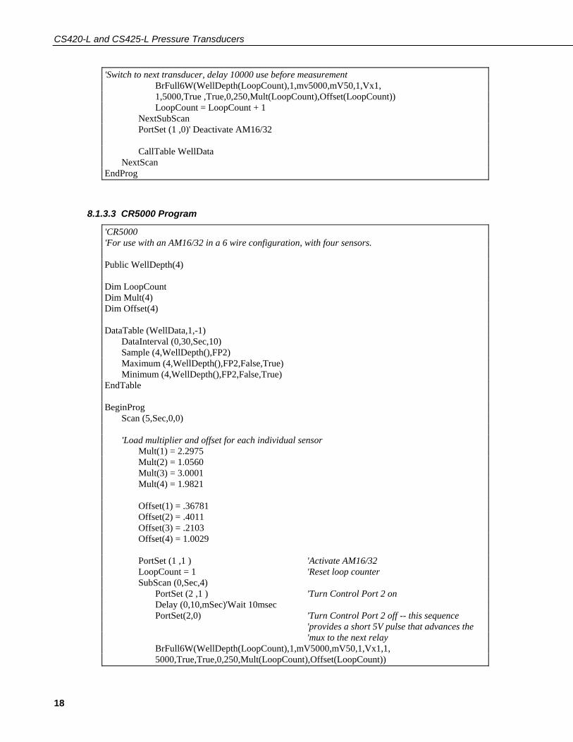
8.1.3.3 CR5000 Program
'CR5000 'For use with an AM16/32 in a 6 wire configuration, with four sensors. Public WellDepth(4) Dim LoopCount Dim Mult(4) Dim Offset(4) DataTable (WellData,1,-1) DataInterval (0,30,Sec,10) Sample (4,WellDepth(),FP2) Maximum (4,WellDepth(),FP2,False,True) Minimum (4,WellDepth(),FP2,False,True) EndTable BeginProg Scan (5,Sec,0,0) 'Load multiplier and offset for each individual sensor Mult(1) = 2.2975 Mult(2) = 1.0560 Mult(3) = 3.0001 Mult(4) = 1.9821 Offset(1) = .36781 Offset(2) = .4011 Offset(3) = .2103 Offset(4) = 1.0029 PortSet (1 ,1 ) 'Activate AM16/32 LoopCount = 1 'Reset loop counter SubScan (0,Sec,4) PortSet (2 ,1 ) 'Turn Control Port 2 on Delay (0,10,mSec)'Wait 10msec PortSet(2,0) 'Turn Control Port 2 off -- this sequence 'provides a short 5V pulse that advances the 'mux to the next relay BrFull6W(WellDepth(LoopCount),1,mV5000,mV50,1,Vx1,1, 5000,True,True,0,250,Mult(LoopCount),Offset(LoopCount))
18

CS420-L and CS425-L Pressure Transducers
LoopCount = LoopCount + 1 NextSubScan PortSet (1 ,0)' Deactivate AM16/32 CallTable WellData NextScan EndProg
8.1.4 Edlog Example The following program is for the CR10(X); a CR23X is programmed similarly.
Each sensor has an independent multiplier and offset that must be applied. To determine multiplier (M) and offset, see the Multiplier and Offset sections.
NOTE
* Table 1 Program 01: 60 Execution Interval (seconds) ; Set Reset on AM16/32A Multiplexer: 1: Do (P86) 1: 41 Set Port 1 High 2: Beginning of Loop (P87) 1: 0000 Delay 2: 4 Loop Count 3: Do (P86) 1: 72Pulse Port 2 4: Excitation with Delay (P22) 1: 1 Ex Channel 2: 0 Delay w/Ex (units = 0.01 sec) 3: 1 Delay after Ex (units = 0.01 sec) 4: 0 mV Excitation ; Measure Druck Pressure Transducer 5: Full Bridge w/mV Excit (P9) 1: 1 Rep 2: 5 2500 mV Slow Ex Range 3: 3 25 mV Slow Br Range 4: 1 DIFF Chan 5: 1 Excite all reps w/Exchan 1 6: 2500 mV Excitation 7: 1-- Loc [DEPTH_FT] (--Index Input Loc.1-4) 8: 1 Mult 9: 0 Offset
19

CS420-L and CS425-L Pressure Transducers
6: End (P95) ; Deactivate Multiplexer 7: Do (P86) 1: 51 Set Port 1 Low ; Adjust sensor readings for multiplier and ; offset: 8: Scaling Array (A*Loc + B) (P53) 1: 1 Start Loc [DEPTH_FT] 2: 2.2975 A1 ;Multiplier #1 3: .36781 B1 ;Offset #1 4: 1.0560 A2 ;Multiplier #2 5: .4011 B2 ;Offset #2 6: 3.0001 A3 ;Multiplier #3 7: .2103 B3 ;Offset #3 8: 1.9821 A4 ;Multiplier #4 9: 1.0029 B4 ;Offset #4 ; Record average depth every hour. 9: If Time is (P92) 1: 0000 Minutes (seconds --) into a 2: 60 Minute Interval (same units as above) 3: 10 Set output flag high (Flag 0) 10: Real Time (P77) 1: 110 Day, Hour/Minute 11: Average (P71) 1: 4 Reps 2: 1 Loc [DEPTH_FT]
9. Maintenance Periodic evaluation of the desiccant is vital for keeping the vent tube dry. To assess the effectiveness of the desiccant, use one of the following:
• An indicating desiccant that changes color when it’s losing its drying power
• An enclosure humidity indicator such as our #6571 humidity indicator card
9.1 Every Visit, At Least Monthly • Collect data
• Visually inspect wiring and physical conditions
20

CS420-L and CS425-L Pressure Transducers
• Check indicating desiccant or enclosure humidity indicator; service desiccant if necessary
• Check battery condition (inspect physical appearance and use a keyboard display or laptop to view the battery voltage)
• Check all sensor readings (using keyboard display or laptop); adjust transducer offsets if necessary
• Check recent data using keyboard display or laptop
• Perform routine maintenance suggested by manufacturers
See datalogger manual for more information about using a keyboard display or laptop to view battery voltage, sensor readings, and recent data.
NOTE
9.2 Every Three Months • Change batteries (as needed--may be less often)
• Replace enclosure desiccants
• Check calibration of all sensors
• Inspect probe cable conditions for deterioration or damage
• Check wire connections ensuring they are still secure
9.3 Every Two to Three Years or on a Rotating Schedule Send the transducers to the factory or laboratory for inspection and have them serviced and/or replaced as needed.
10. Troubleshooting The most common causes of erroneous pressure transducer data include:
• poor sensor connections to the datalogger
• damaged cables
• damaged transducers
• moisture in the vent tube
21

CS420-L and CS425-L Pressure Transducers
22
To troubleshoot, do the following:
• Check your connections to the datalogger. Look for loose or broken wires, and moisture at the points of connection.
• Inspect the pressure transducer cable for wear, stress, or other indications of damage.
• Check the vent tube for plugging and condensation.

This is a blank page.

Campbell Scientific Companies
Campbell Scientific, Inc. (CSI) 815 West 1800 North Logan, Utah 84321 UNITED STATES
www.campbellsci.com [email protected]
Campbell Scientific Africa Pty. Ltd. (CSAf)
PO Box 2450 Somerset West 7129
SOUTH AFRICA www.csafrica.co.za
Campbell Scientific Australia Pty. Ltd. (CSA) PO Box 444
Thuringowa Central QLD 4812 AUSTRALIA www.campbellsci.com.au [email protected]
Campbell Scientific do Brazil Ltda. (CSB)
Rua Luisa Crapsi Orsi, 15 Butantã CEP: 005543-000 São Paulo SP BRAZIL
www.campbellsci.com.br [email protected]
Campbell Scientific Canada Corp. (CSC)
11564 - 149th Street NW Edmonton, Alberta T5M 1W7
CANADA www.campbellsci.ca
Campbell Scientific Ltd. (CSL) Campbell Park
80 Hathern Road Shepshed, Loughborough LE12 9GX
UNITED KINGDOM www.campbellsci.co.uk [email protected]
Campbell Scientific Ltd. (France)
Miniparc du Verger - Bat. H 1, rue de Terre Neuve - Les Ulis
91967 COURTABOEUF CEDEX FRANCE
www.campbellsci.fr [email protected]
Campbell Scientific Spain, S. L.
Psg. Font 14, local 8 08013 Barcelona
SPAIN www.campbellsci.es [email protected]
Please visit www.campbellsci.com to obtain contact information for your local US or International representative.