Embed Size (px)
Citation preview

3/05/03 ©UCB Spring 2003 CS152 / Kubiatowicz
Lec11.1
CS 152 Computer Architecture and Engineering
Lecture 11
Multicycle Controller Design
March 5, 2003
John Kubiatowicz (www.cs.berkeley.edu/~kubitron)
lecture slides: http://inst.eecs.berkeley.edu/~cs152/

3/05/03 ©UCB Spring 2003 CS152 / Kubiatowicz
Lec11.2
Review: High Level Design° Design Process• Design Entry: Schematics, HDL, Compilers
• High Level Analysis: Simulation, Testing, Assertions
• Technology Mapping: Turn design into physical implementation
• Low Level Analysis: Check out Timing, Setup/Hold, etc
° Verilog – Three programming styles• Structural: Like a Netlist
- Instantiation of modules + wires between them
• Dataflow: Higher Level
- Expressions instead of gates
• Behavioral: Hardware programming
- Full flow-control mechanisms
- Registers, variables
- File I/O, consol display, etc

3/05/03 ©UCB Spring 2003 CS152 / Kubiatowicz
Lec11.3
Review: Testing: Make sure that things work° Testing methodologies
• Understand what correct behavior iswhen you design things
- Collect vectors for later use
• Build monitor modules to check assertions of correct values
• Produce a regression test
- Set of tests to run each time something changes
° Types of test (Doug Clark):• Directed Vectors – test explicit behavior
• Random Vectors – apply random values or orderings to device
• Daemons – continuous error insertion
° Monitor modules:• Check to see if invariants are maintained
during long running simulations
Alewife Numbers
3/05/03 ©UCB Spring 2003 CS152 / Kubiatowicz
Lec11.4
module monitorsum32(carry,sum,A,B );input [31:0] A,B;output [31:0] sum;output carry;reg [31:0] predsum;reg precarry;
// The “real” addersum32 mysum (carry,sum,A,B);
`ifndef synthesis // This checker code only for simulationalways @(A or B)
begin #100 //wait for output to settle (don’t make too long!){predcarry,predsum} = A + B;
if ((carry != predcarry) || (sum != predsum))$display(“>>> Mismatch: 0x%x+0x%x->0x%x carry %x”,
A,B,sum,carry);end
`endifendmodule
Review: Monitor Modules: Passthrough testing

3/05/03 ©UCB Spring 2003 CS152 / Kubiatowicz
Lec11.5
Lab4 version: monitors and benches° Idea: wrap testing infrastructure around devices under
test (DUT)
° Include test vectors that are supposed to detect errors in implementation. Even strange ones…
° Can (and probably should in later labs) include assert statements to check for “things that should never happen”
Test Bench
Device UnderTest
Inline vectorsAssert StatementsFile IO (either for patternsor output diagnostics)
Inline Monitor
Output in readableformat (disassembly)Assert Statements
Complete Top-Level Design

3/05/03 ©UCB Spring 2003 CS152 / Kubiatowicz
Lec11.6
The Big Picture: Where are We Now?
° The Five Classic Components of a Computer
° Today’s Topics: • Microprogramed control
• Administrivia; Courses
• Microprogram it yourself
• Exceptions
• Intro to Pipelining (if time permits)
Control
Datapath
Memory
Processor
Input
Output

3/05/03 ©UCB Spring 2003 CS152 / Kubiatowicz
Lec11.7
Alternative multicycle datapath (book)
° Miminizes Hardware: 1 memory, 1 adder
IdealMemoryWrAdrDin
RAdr
32
32
32Dout
MemWr
32
AL
U
3232
ALUOp
ALUControl
32
IRWr
Instru
ction R
eg
32
Reg File
Ra
Rw
busW
Rb5
5
32busA
32busB
RegWr
Rs
Rt
Mu
x
0
1
Rt
Rd
PCWr
ALUSelA
Mux 01
RegDst
Mu
x
0
1
32
PC
MemtoReg
Extend
ExtOp
Mu
x
0
132
0
1
23
4
16Imm 32
<< 2
ALUSelB
Mu
x1
0
32
Zero
ZeroPCWrCond PCSrc
32
IorD
Mem
Data R
eg
AL
U O
ut
B
A
3/05/03 ©UCB Spring 2003 CS152 / Kubiatowicz
Lec11.8
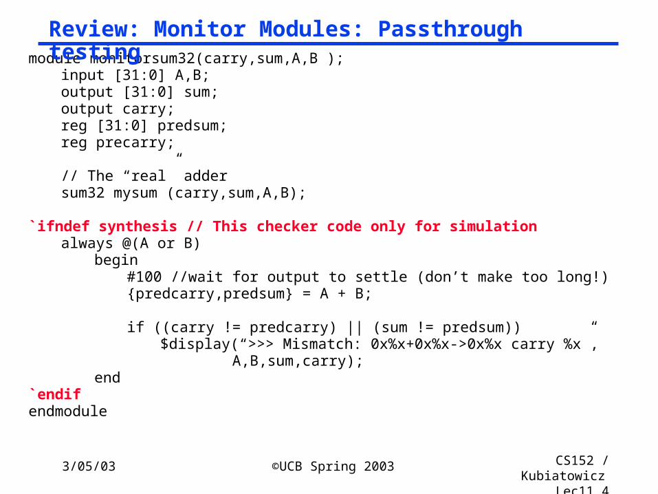
New Finite State Machine (FSM) Spec
IR <= MEM[PC]PC <= PC + 4
R-type
ALUout <= A fun B
R[rd] <= ALUout
ALUout <= A or ZX
R[rt] <= ALUout
ORi
ALUout <= A + SX
R[rt] <= M
M <= MEM[ALUout]
LW
ALUout <= A + SX
MEM[ALUout] <= B
SW
“instruction fetch”
“decode”
Execute
Memory
Write-back
0000
0001
0100
0101
0110
0111
1000
1001
1010
1011
1100
BEQ
0010
0011
If A = B then PC <= ALUout
ALUout <= PC +SX
Q: How improveto do something instate 0001?

3/05/03 ©UCB Spring 2003 CS152 / Kubiatowicz
Lec11.9
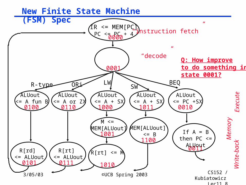
Finite State Machine (FSM) Spec
IR <= MEM[PC]PC <= PC + 4
R-type
ALUout <= A fun B
R[rd] <= ALUout
ALUout <= A or ZX
R[rt] <= ALUout
ORi
ALUout <= A + SX
R[rt] <= M
M <= MEM[ALUout]
LW
ALUout <= A + SX
MEM[ALUout] <= B
SW
“instruction fetch”
“decode”
0000
0001
0100
0101
0110
0111
1000
1001
1010
1011
1100
BEQ
0010
If A = B then PC <= ALUout
ALUout <= PC +SX
Execute
Memory
Write-back

3/05/03 ©UCB Spring 2003 CS152 / Kubiatowicz
Lec11.10
sequencercontrol
micro-PC-sequencer:fetch,dispatch,sequential
DispatchROM
Opcode
Inputs
Recap: Microprogramming
° Microprogramming is a fundamental concept• implement an instruction set by building a very simple processor
and interpreting the instructions
• essential for very complex instructions and when few register transfers are possible
• overkill when ISA matches datapath 1-1
-Code ROM
To DataPath
DecodeDecode
datapath control
microinstruction ()

3/05/03 ©UCB Spring 2003 CS152 / Kubiatowicz
Lec11.11
Recap: Microprogramming° Microprogramming is a convenient method for implementing structured control state diagrams:
• Random logic replaced by microPC sequencer and ROM
• Each line of ROM called a instruction: contains sequencer control + values for control points
• limited state transitions: branch to zero, next sequential,branch to instruction address from displatch ROM
° Horizontal Code: one control bit in Instruction for every control line in datapath
° Vertical Code: groups of control-lines coded together in Instruction (e.g. possible ALU dest)
° Control design reduces to Microprogramming• Part of the design process is to develop a “language” that
describes control and is easy for humans to understand

3/05/03 ©UCB Spring 2003 CS152 / Kubiatowicz
Lec11.12
Recap: “Macroinstruction” Interpretation
MainMemory
executionunit
controlmemory
CPU
ADDSUBAND
DATA
.
.
.
User program plus Data
this can change!
AND microsequence
e.g., Fetch Calc Operand Addr Fetch Operand(s) Calculate Save Answer(s)
one of these ismapped into oneof these

3/05/03 ©UCB Spring 2003 CS152 / Kubiatowicz
Lec11.13
Designing a Microinstruction Set
1) Start with list of control signals
2) Group signals together that make sense (vs. random): called “fields”
3) Place fields in some logical order (e.g., ALU operation & ALU operands first and microinstruction sequencing last)
4) To minimize the width, encode operations that will never be used at the same time
5) Create a symbolic legend for the microinstruction format, showing name of field values and how they set the control signals
• Use computers to design computers

3/05/03 ©UCB Spring 2003 CS152 / Kubiatowicz
Lec11.14
Again: Alternative multicycle datapath (book)
° Miminizes Hardware: 1 memory, 1 adder
IdealMemoryWrAdrDin
RAdr
32
32
32Dout
MemWr
32
AL
U
3232
ALUOp
ALUControl
32
IRWr
Instru
ction R
eg
32
Reg File
Ra
Rw
busW
Rb5
5
32busA
32busB
RegWr
Rs
Rt
Mu
x
0
1
Rt
Rd
PCWr
ALUSelA
Mux 01
RegDst
Mu
x
0
1
32
PC
MemtoReg
Extend
ExtOp
Mu
x
0
132
0
1
23
4
16Imm 32
<< 2
ALUSelB
Mu
x1
0
32
Zero
ZeroPCWrCond PCSrc
32
IorD
Mem
Data R
eg
AL
U O
ut
B
A

3/05/03 ©UCB Spring 2003 CS152 / Kubiatowicz
Lec11.15
1&2) Start with list of control signals, grouped into fields
Signal name Effect when deasserted Effect when assertedALUSelA 1st ALU operand = PC 1st ALU operand = Reg[rs]RegWrite None Reg. is written MemtoReg Reg. write data input = ALU Reg. write data input = memory RegDst Reg. dest. no. = rt Reg. dest. no. = rdMemRead None Memory at address is read,
MDR <= Mem[addr]MemWrite None Memory at address is written IorD Memory address = PC Memory address = SIRWrite None IR <= MemoryPCWrite None PC <= PCSourcePCWriteCond None IF ALUzero then PC <= PCSourcePCSource PCSource = ALU PCSource = ALUoutExtOp Zero Extended Sign Extended
Sin
gle
Bit
Con
trol
Signal name Value Effect ALUOp 00 ALU adds 01 ALU subtracts 10 ALU does function code
11 ALU does logical OR ALUSelB 00 2nd ALU input = 4 01 2nd ALU input = Reg[rt] 10 2nd ALU input = extended,shift left 2 11 2nd ALU input = extended
Mu
ltip
le B
it C
ontr
ol

3/05/03 ©UCB Spring 2003 CS152 / Kubiatowicz
Lec11.16
3&4) Microinstruction Format: unencoded vs. encoded fields
Field Name Width Control Signals Set
wide narrow
ALU Control 4 2 ALUOp
SRC1 2 1 ALUSelA
SRC2 5 3 ALUSelB, ExtOp
ALU Destination 3 2 RegWrite, MemtoReg, RegDst
Memory 3 2 MemRead, MemWrite, IorD
Memory Register 1 1 IRWrite
PCWrite Control 3 2 PCWrite, PCWriteCond, PCSource
Sequencing 3 2 AddrCtl
Total width 24 15 bits

3/05/03 ©UCB Spring 2003 CS152 / Kubiatowicz
Lec11.17
5) Legend of Fields and Symbolic Names
Field Name Values for Field Function of Field with Specific ValueALU Add ALU adds
Subt. ALU subtractsFunc code ALU does function codeOr ALU does logical OR
SRC1 PC 1st ALU input = PCrs 1st ALU input = Reg[rs]
SRC2 4 2nd ALU input = 4Extend 2nd ALU input = sign ext. IR[15-0]Extend0 2nd ALU input = zero ext. IR[15-0] Extshft 2nd ALU input = sign ex., sl IR[15-0]rt 2nd ALU input = Reg[rt]
destination rd ALU Reg[rd] = ALUout rt ALU Reg[rt] = ALUout
rt Mem Reg[rt] = Mem Memory Read PC Read memory using PC
Read ALU Read memory using ALUout for addrWrite ALU Write memory using ALUout for addr
Memory register IR IR = MemPC write ALU PC = ALU
ALUoutCond IF ALU Zero then PC = ALUoutSequencing Seq Go to sequential µinstruction
Fetch Go to the first microinstructionDispatch Dispatch using ROM.

3/05/03 ©UCB Spring 2003 CS152 / Kubiatowicz
Lec11.18
Administrivia° Midterm I next Wednesday
• 5:30 - 8:30 probably in 277 Cory • Bring a Calculator!• One 8 1/2 by 11 page (both sides) of notes• Make up exam: Tuesday 5:30 – 8:30 in 606 Soda Hall
° Materials through Chapter 5, Appendix A, B & C° Review session this Sunday 7:00 306 Soda° Lab 3:
• Please include a file called instructions.txt that give explicit details on how to run the simulation for 3c
° Tomorrow: Must come to section!• Creating groups: 4 or 5 per group• Also: Please read the Doug Clark paper on testing before
section – you are going to discuss it° Lab 4 breakdown due midnight Friday
• EMail to your TA• This is a complicated lab – may need to give updates as we
get the boards installed

3/05/03 ©UCB Spring 2003 CS152 / Kubiatowicz
Lec11.19
Quick check: what do these fieldnames mean?
Code Name RegWrite MemToRegRegDest
00 --- 0 X X01 rd ALU 1 0 110 rt ALU 1 0 011 rt MEM 1 1 0
Code Name ALUSelB ExtOp000 --- X X001 4 00 X010 rt 01 X011 ExtShft 10 1100 Extend 11 1111 Extend0 11 0
Destination:
SRC2:

3/05/03 ©UCB Spring 2003 CS152 / Kubiatowicz
Lec11.20
Specific Sequencer from last lecture
Sequencer-based control unit from last lecture• Called “microPC” or “µPC” vs. state register
Code Name Effect 00 fetch Next µaddress = 0 01 dispatch Next µaddress = dispatch ROM 10 seq Next µaddress = µaddress + 1
ROM:
Opcode
microPC
1
µAddressSelectLogic
Adder
ROM
Mux
0012
R-type 000000 0100BEQ 000100 0011ori 001101 0110LW 100011 1000SW 101011 1011

3/05/03 ©UCB Spring 2003 CS152 / Kubiatowicz
Lec11.21
Microprogram it yourself!
Label ALU SRC1 SRC2 Dest. Memory Mem. Reg. PC Write SequencingFetch: Add PC 4 Read PC IR ALU Seq

3/05/03 ©UCB Spring 2003 CS152 / Kubiatowicz
Lec11.23
An Alternative MultiCycle DataPath
° In each clock cycle, each Bus can be used to transfer from one source
° µ-instruction can simply contain B-Bus and W-Dst fields
RegFile
A
B
A-Bus
B Bus
IR S mem
W-Bus
PC
instmem
nextPC ZX SX
3/05/03 ©UCB Spring 2003 CS152 / Kubiatowicz
Lec11.24
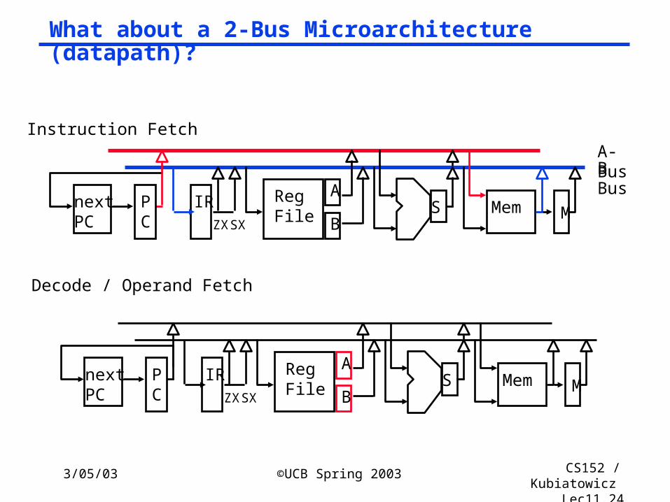
What about a 2-Bus Microarchitecture (datapath)?
RegFile
A
B
A-BusB Bus
IR SPC
nextPC ZXSX
Mem
RegFile
A
BIR SP
CnextPC ZXSX
Mem
Instruction Fetch
Decode / Operand Fetch
M
M

3/05/03 ©UCB Spring 2003 CS152 / Kubiatowicz
Lec11.25
Load
° What about 1 bus ? 1 adder? 1 Register port?
RegFile
A
BIR SP
CnextPC ZXSX
Mem
RegFile
A
BIR SP
CnextPC ZXSX
Mem
RegFile
A
BIR SP
CnextPC ZXSX
Mem
Execute
addr
M
M
M
Mem
Write-back

3/05/03 ©UCB Spring 2003 CS152 / Kubiatowicz
Lec11.26
Legacy Software and Microprogramming
° IBM bet company on 360 Instruction Set Architecture (ISA): single instruction set for many classes of machines
• (8-bit to 64-bit)
° Stewart Tucker stuck with job of what to do about software compatibility
• If microprogramming could easily do same instruction set on many different microarchitectures, then why couldn’t multiple microprograms do multiple instruction sets on the same microarchitecture?
• Coined term “emulation”: instruction set interpreter in microcode for non-native instruction set
• Very successful: in early years of IBM 360 it was hard to know whether old instruction set or new instruction set was more frequently used

3/05/03 ©UCB Spring 2003 CS152 / Kubiatowicz
Lec11.27
Microprogramming Pros and Cons
° Ease of design
° Flexibility• Easy to adapt to changes in organization, timing, technology
• Can make changes late in design cycle, or even in the field
° Can implement very powerful instruction sets (just more control memory)
° Generality• Can implement multiple instruction sets on same machine.
• Can tailor instruction set to application.
° Compatibility• Many organizations, same instruction set
° Costly to implement
° Slow

3/05/03 ©UCB Spring 2003 CS152 / Kubiatowicz
Lec11.28
Summary° Microprogramming is a fundamental concept
• implement an instruction set by building a very simple processor and interpreting the instructions
• essential for very complex instructions and when few register transfers are possible
• Control design reduces to Microprogramming
° Design of a Microprogramming language1. Start with list of control signals
2. Group signals together that make sense (vs. random): called “fields”
3. Place fields in some logical order (e.g., ALU operation & ALU operands first and microinstruction sequencing last)
4. To minimize the width, encode operations that will never be used at the same time
5. Create a symbolic legend for the microinstruction format, showing name of field values and how they set the control signals

3/05/03 ©UCB Spring 2003 CS152 / Kubiatowicz
Lec11.29
Thought: Microprogramming one inspiration for RISC
° If simple instruction could execute at very high clock rate…
° If you could even write compilers to produce microinstructions…
° If most programs use simple instructions and addressing modes…
° If microcode is kept in RAM instead of ROM so as to fix bugs …
° If same memory used for control memory could be used instead as cache for “macroinstructions”…
° Then why not skip instruction interpretation by a microprogram and simply compile directly into lowest language of machine? (microprogramming is overkill when ISA matches datapath 1-1)