Embed Size (px)
Citation preview

INST
RU
CT
ION
MA
NU
AL
CS125Present Weather Sensor
July 2014
Copyright © 2013 - 2014Campbell Scienti f ic Ltd.


PLEASE READ FIRST About this manual
Some useful conversion factors:
Area: 1 in2 (square inch) = 645 mm2
Length: 1 in. (inch) = 25.4 mm 1 ft (foot) = 304.8 mm 1 yard = 0.914 m 1 mile = 1.609 km
Mass: 1 oz. (ounce) = 28.35 g 1 lb (pound weight) = 0.454 kg
Pressure: 1 psi (lb/in2) = 68.95 mb
Volume: 1 UK pint = 568.3 ml 1 UK gallon = 4.546 litres 1 US gallon = 3.785 litres
Recycling information At the end of this product’s life it should not be put in commercial or domestic refuse but sent for recycling. Any batteries contained within the product or used during the products life should be removed from the product and also be sent to an appropriate recycling facility.
Campbell Scientific Ltd can advise on the recycling of the equipment and in some cases arrange collection and the correct disposal of it, although charges may apply for some items or territories.
For further advice or support, please contact Campbell Scientific Ltd, or your local agent.
Campbell Scientific Ltd, Campbell Park, 80 Hathern Road, Shepshed, Loughborough, LE12 9GX, UK Tel: +44 (0) 1509 601141 Fax: +44 (0) 1509 601091
Email: [email protected] www.campbellsci.co.uk
2
Contents PDF viewers note: These page numbers refer to the printed version of this document. Use the Adobe Acrobat® bookmarks tab for links to specific sections.
1. Introduction ................................................................. 1 1.1 Version Information .................................................................................. 1 1.2 General Safety .......................................................................................... 2 1.3 Sensor Unit Safety .................................................................................... 2
2. Technical specification .............................................. 3
3. Electrical specification ............................................... 3
4. Supported data rates for RS232 and RS485 ............. 4
5. Environmental specifications .................................... 5
6. Mechanical specifications .......................................... 5
7. Installation procedure ................................................ 5 7.1 Equipment grounding ............................................................................... 7 7.2 Mounting the CS125 ................................................................................. 7 7.3 Optional Campbell Scientific Mount ........................................................ 9
8. CS125 internal connectors’ description .................. 11 8.1 CS125 recommended wiring using Campbell Scientific cables ............. 13
9. CS215 T/RH Sensor .................................................. 14
10. Functions of the internal switches ........................ 15
11. Message Formats: A breakdown of the different default outputs of the CS125 –
Basic/Partial/Full ............................................... 16 11.1 Visibility only messages (CS120 emulation) ........................................ 17 11.2 Messages with SYNOP Present Weather Codes ................................... 18 11.3 Messages with METAR Present Weather Codes .................................. 19 11.4 Example CS125 message outputs ......................................................... 22 11.5 SYNOP Codes produced by the CS125 ................................................ 23 11.6 METAR Codes produced by the CS125 ............................................... 24

3
12. Interface methods – Device Configuration Utility/Command Line/Menu ................................. 24
12.1 Configuring a PC for talking to the CS125 ........................................... 25
13. Definition of the variables that can be set by the user on the CS125 ......................................... 25
14. Command line mode .............................................. 27 14.1 The SET command ............................................................................... 28 14.1.1 Example of a SET Command .................................................... 29 14.2 The SETNC Command ......................................................................... 29 14.2.1 Example of a SETNC Command .............................................. 29 14.3 The GET command ............................................................................... 29 14.4 The POLL command – Polling the CS125 ........................................... 31
15. Entering the CS125 menu system ......................... 32
16. Calibrating the CS125 ............................................. 36
17. Performing a firmware update ............................... 39
18. Cleaning .................................................................. 40
19. Lubricating the enclosure screws ......................... 41
20. Desiccant ................................................................. 41
Appendices
A. CS125 Block Diagram ............................................ A-1
B. Example C code of the CCITT CRC ....................... B-1
C. Example CRBasic programs ................................ C -1

1
CS125 Present Weather Sensor
1. Introduction The CS125 is an infrared forward scatter present weather sensor for automatic weather stations including road, marine and airport based stations. The CS125 uses the well-established forward scatter system for visibility measurement, utilising a 42º scatter angle. The CS125 uses high speed sampling to reduce missed events such as rain and hail and improves response to other suddenly changing conditions. When an optional CS215 temperature and RH sensor is connected, the CS125 can distinguish wet and dry obscuration (for example mist and haze) and make more precise discrimination between liquid and frozen precipitation.
1.1 Version Information
Manual Version Revisions
1.0 None

CS125 Present Weather Sensor
2
1.2 General Safety This manual provides important safety considerations for the installation, operation and maintenance of the CS125. These safety considerations are classified into three levels:
Warnings alert the installer or user to serious hazards. Ignoring these warnings could result in injury or death and/or irrevocable damage to the sensor unit.
Cautions warn of potential hazards. Ignoring these cautions could result in the sensor being damaged and data being lost.
Notes highlight useful information in the installation, use and maintenance of this product. These should be followed carefully in order to gain the maximum benefit from the use of this product.
1.3 Sensor Unit Safety The CS125 sensor has been checked for safety before leaving the factory and contains no internally replaceable or modifiable parts.
Do not modify the CS125 unit. Such modifications will lead to damage of the unit and could expose users to dangerous light levels and voltages.
In unusual failure modes and environmental conditions the sensor hood could become hot. In normal operation they will be at ambient temperature or slightly above.
Ensure that the correct voltage supply is provided to the sensor.
WARNING
CAUTION
NOTE
WARNING
WARNING
CAUTION

User Guide
3
2. Technical specification Minimum
Value Nominal
Value Maximum
Value Visibility characteristics
Reported Visibility (metric) 12 metres - 32,000 metres
Reported Visibility (imperial) 39 feet - 104,985 feet
Visibility accuracy up to 10,000m - +/-10% - Visibility accuracy up to 20,000m - +/-20% -
Optical characteristics LED centre wavelength - 850nm - LED spectral bandwidth - +/-35nm -
Pulse characteristics Light pulse rate - 1KHz -
3. Electrical specification Minimum
Value Nominal
Value Maximum
Value Main power supply for DSP and dew heaters Power supply, +12V connection (DC only)
9V 12V 28V(1)
Current consumption sampling continuously with dew heaters active (at 12V DC)
- 200mA 248mA
Current consumption sampling continuously with dew heaters disabled (at 12V DC)
- 110mA 151mA
Current consumption without any sampling occurring and dew heaters disabled (at 12V DC)
- 21mA 30mA
Active power consumption with dew heaters and RS232 communications interface active(2,3) (at 12V DC)
- 200mA 250mA
Hood heater power supply Hood heater voltage (AC or DC) - 24V(3) 30V(4) Hood heater wattage (at 24V AC or DC)
- 60W(5) -
RS232 Communications RS232 input threshold Low 0.8V 1.5V - RS232 input threshold High - 2.0V 2.4V RS232 input absolute maximum -15V - +15V RS232 input resistance 12K - - RS232 output voltage low - - 0.4V

CS125 Present Weather Sensor
4
RS232 output voltage high (into 3K )
4.4V - -
RS485 Communications RS485 input threshold voltage -0.2V - +0.2V RS485 output (Unloaded) - - 5V RS485 output (Load 50 ) 2V - - Maximum voltage at any terminal(6) -7V - +7V
User alarm outputs User output high level (at 85ºC) 3.8V - - User output high level (at 25ºC ) 4.13V - - User output low (All temperatures) 0.25V - 0.55V User output current - - 32mA
(1) If a CS215 is being used the supply voltage should not exceed 16V.
(2) The RS232 communications interface will automatically turn itself off when not transmitting.
(3) If hood heaters are not being used ensure `Hood heater override’ (details in Section 13) is set to off.
(4) It is recommended that the hood heaters are run at 24V AC/DC. It’s possible to run the heaters at any voltage below 24V but the heaters will generate proportionally less heat reducing their ability to prevent ice build-up.
(5) Each hood takes 30W, 60W is the total for both hoods on the sensor together.
(6) The ground of the CS125 and the earth of any RS485 equipment cannot be further apart than this voltage. A 100 resistor can be used to connect the CS125 RS485 earth to other equipment. This will reduce any parasitic currents and bring the two earths closer together if a direct connection cannot be made.
If a CS215 is being used the supply voltage should not exceed 16V.
4. Supported data rates for RS232 and RS485 Serial setting 8N1 Supported data rates
1200 bps 2400 bps 9600 bps 19200 bps 38400 bps - default 57600 bps 115200 bps
CAUTION

User Guide
5
Supported formats
RS232 (Full duplex only), default RS485 (Half duplex) 8 bit data bytes 1 stop bit Parity checking is not supported as most communication protocols used by
the CS125 have built in checksums as well as checks that communications have been understood
5. Environmental specifications
Minimum Value
Nominal Value
Maximum Value
Sensor temperature ranges Operating temperature -25°C - +60°C Extended operating temperature -40°C - +70°C (1) Storage temperature -40°C - +85°C
Sensor humidity ranges Operating humidity range 0% - 100%
Sensor heater thresholds
Dew heater Turn On - <35°C - Dew heater Turn Off - >40°C - Hood heater Turn On - <5°C - Hood heater Turn Off - >15°C -
(1) Extended temperature ranges are only guaranteed if the sensor has been tested by Campbell Scientific and verified within this temperature range. Some degradation of absolute accuracy can be expected at the extremes of the extended ranges.
6. Mechanical specifications Main body including base mount Height: 447 mm Width: 640 mm Depth: 245 mm Sensor weight: 3 Kg Sensor mounting: Bracket mounts on a vertical pole 32-52.5 mm diameter. The
mounting bracket has cut-outs for band clamps for larger diameter masts.
Shipping weight: 6 Kg (including packing box)
7. Installation procedure The CS125 measures environmental variables and is designed to be located in harsh weather conditions. However there are a few considerations to take into account if accurate and representative data from a site are to be obtained.

CS125 Present Weather Sensor
6
The descriptions in this section are not exhaustive. Please refer to meteorological publications for further information on locating weather instruments
The CS125 should be sited in a position representative of local weather conditions and not of a specific microclimate (unless the analysis of microclimate weather is being sought).
The CS125 has good resistance to background light but it is a good idea to avoid locations where the transmitter is pointing at a light scattering or reflecting surface. Ideally the receiver should point north in the northern hemisphere and south in the southern hemisphere but this is not critical if the field of view does not include a bright and scattering surface.
To give non-microclimatic measurements the CS125 should be sited away from possible physical obstructions that could affect the fall of precipitation. The CS125 should also be positioned away from sources of heat, electrical interference and in such a position as to not have direct light on the sensor lenses. Whenever possible, the CS125 should be located away from windbreaks.
Several zones have been identified upwind and downwind of a windbreak in which the airflow is unrepresentative of the general speed and direction. Eddies are generated in the lee of the windbreak and air is displaced upwind of it. The height and depth of these affected zones varies with the height and to some extent the density of the obstacle.
Generally, a structure disturbs the airflow in an upwind direction for a distance of about twice the height of the structure, and in a downwind direction for a distance of about six times the height. The airflow is also affected to a vertical distance of about twice the height of the structure. Ideally, therefore, the CS125 should be located outside this zone of influence in order to obtain representative values for the region.
In order to reduce the service frequency with the unit, the CS125 should be placed away from sources of contamination, in the case of roadside monitoring; larger mounting poles can be used. More regular maintenance will be required when the instrument is placed in areas where contamination is unavoidable or where measurements may be safety critical.
The WMO recommend a sample volume height of 1.5 m. However, for applications such as aviation or road visibility other heights may be appropriate.
NOTE
Receiver
Transmitter

User Guide
7
If operating a CS125 indoors it is likely that there will be sources of light and/or reflections that will create false readings and erratic results.
If carrying out simple checks, blocking a lens or the sample volume will simulate an INCREASE in visibility not a decrease.
7.1 Equipment grounding
The CS125 must be properly grounded by taking a ground wire with a minimum cross sectional area of 6 mm2 and maximum length of 5 m from the brass grounding lug in the lower face of the electronics enclosure to an adequate grounding point. The pole and foundations of a pole mounted installation will provide some basic lightning protection and protection against radio frequency interference and should also be correctly grounded.
7.2 Mounting the CS125 A pole mounting kit is supplied with the CS125. To mount the CS125 onto a pole:
1. Offer up the DSP plate to the pole and present the `V’ bolts from the other side as shown.
2. Clamp the pole between the DSP plate and brackets by tightening using the nuts and washers provided.
3. If a power supply enclosure has been supplied with the sensor it can be mounted on the pole, near its base using the brackets supplied with the enclosure. Alternatively the power supply can be mounted elsewhere, e.g. on a wall at some distance from the sensor. The power supply enclosure should be
NOTE
NOTE
CS125 Present Weather Sensor
8
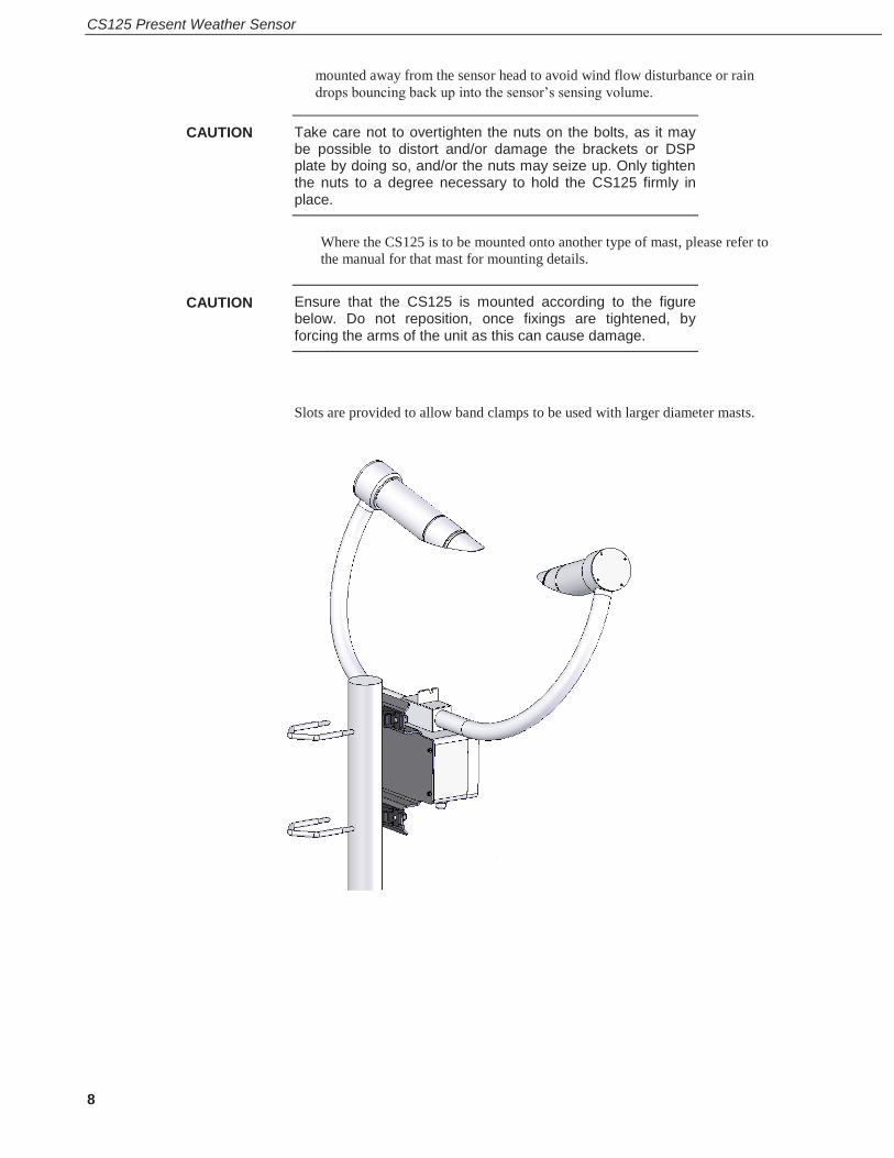
mounted away from the sensor head to avoid wind flow disturbance or rain drops bouncing back up into the sensor’s sensing volume.
Take care not to overtighten the nuts on the bolts, as it may be possible to distort and/or damage the brackets or DSP plate by doing so, and/or the nuts may seize up. Only tighten the nuts to a degree necessary to hold the CS125 firmly in place.
Where the CS125 is to be mounted onto another type of mast, please refer to the manual for that mast for mounting details.
Ensure that the CS125 is mounted according to the figure below. Do not reposition, once fixings are tightened, by forcing the arms of the unit as this can cause damage.
Slots are provided to allow band clamps to be used with larger diameter masts.
CAUTION
CAUTION

User Guide
9
7.3 Optional Campbell Scientific Mount A Campbell Scientific `optical sensor mount’, part number 009354, is available. This will put the sample volume at about 1.5 m in compliance with the WMO `Guide to Meteorological Instruments and Methods of Observation’, 7th Edition, Section 9.3.4.
If one is to be used, follow the installation instructions below.
The mount should be installed on a concrete foundation. If one does not already exist then a concrete foundation should be constructed at least 600 mm square and 600 mm deep. Ensure the ground consistency is not too loose and will be able to support the mount and concrete foundation.

CS125 Present Weather Sensor
10
Drill four 12 mm diameter holes using the mount base as a template or following the drawing below to a depth of 77 mm.
Clean the holes of all debris.
Place washers and nuts on the ends of the wedge anchors supplied (to protect the threads during installation).
Hammer the wedge anchors into the holes until the start of the threads are below the surface.
Tighten the nuts until about 25 mm of thread protrudes above the surface.
Remove the washers and nuts from the protruding length screw. Then lower the mount into place.
Finally secure the mount with the washers and nuts.
If the surface is not level and flat it may be necessary to add washers under the base on one or more of the foundation screws.
User Guide
11
8. CS125 internal connectors’ description
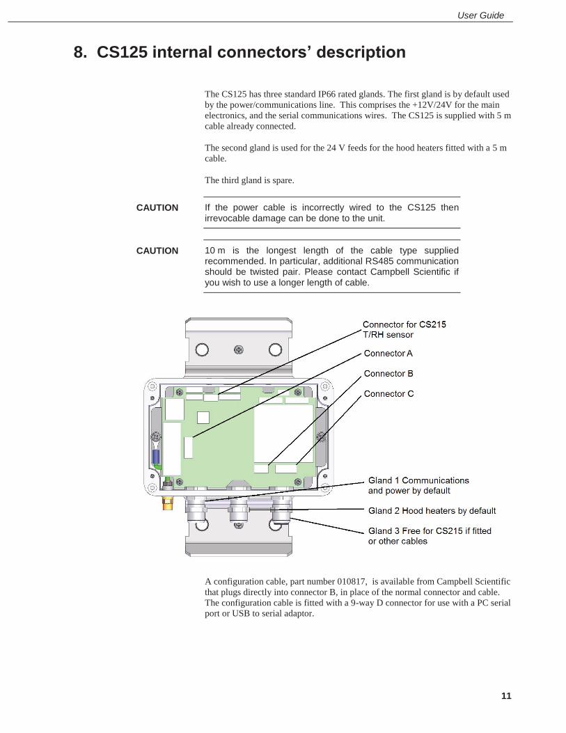
The CS125 has three standard IP66 rated glands. The first gland is by default used by the power/communications line. This comprises the +12V/24V for the main electronics, and the serial communications wires. The CS125 is supplied with 5 m cable already connected.
The second gland is used for the 24 V feeds for the hood heaters fitted with a 5 m cable.
The third gland is spare.
If the power cable is incorrectly wired to the CS125 then irrevocable damage can be done to the unit.
10 m is the longest length of the cable type supplied recommended. In particular, additional RS485 communication should be twisted pair. Please contact Campbell Scientific if you wish to use a longer length of cable.
A configuration cable, part number 010817, is available from Campbell Scientific that plugs directly into connector B, in place of the normal connector and cable. The configuration cable is fitted with a 9-way D connector for use with a PC serial port or USB to serial adaptor.
CAUTION
CAUTION
CS125 Present Weather Sensor
12
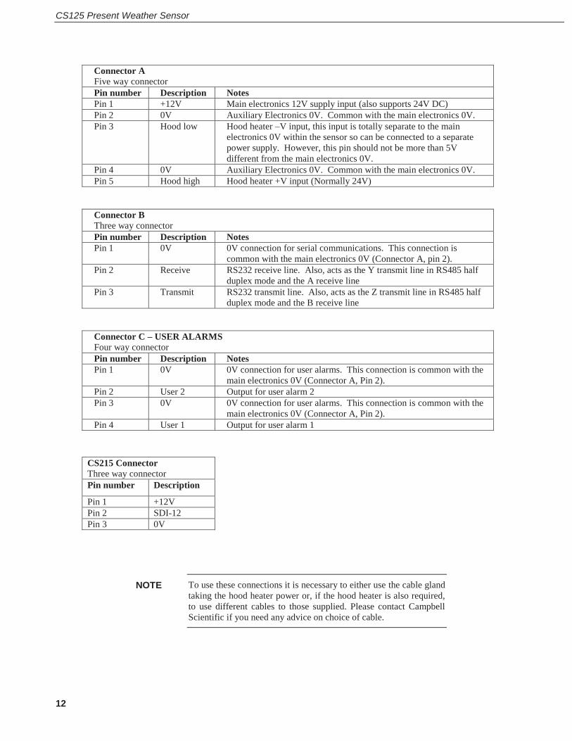
Connector A Five way connector Pin number Description Notes Pin 1 +12V Main electronics 12V supply input (also supports 24V DC) Pin 2 0V Auxiliary Electronics 0V. Common with the main electronics 0V. Pin 3 Hood low Hood heater –V input, this input is totally separate to the main
electronics 0V within the sensor so can be connected to a separate power supply. However, this pin should not be more than 5V different from the main electronics 0V.
Pin 4 0V Auxiliary Electronics 0V. Common with the main electronics 0V. Pin 5 Hood high Hood heater +V input (Normally 24V)
Connector B Three way connector Pin number Description Notes Pin 1 0V 0V connection for serial communications. This connection is
common with the main electronics 0V (Connector A, pin 2). Pin 2 Receive RS232 receive line. Also, acts as the Y transmit line in RS485 half
duplex mode and the A receive line Pin 3 Transmit RS232 transmit line. Also, acts as the Z transmit line in RS485 half
duplex mode and the B receive line
Connector C – USER ALARMS Four way connector Pin number Description Notes Pin 1 0V 0V connection for user alarms. This connection is common with the
main electronics 0V (Connector A, Pin 2). Pin 2 User 2 Output for user alarm 2 Pin 3 0V 0V connection for user alarms. This connection is common with the
main electronics 0V (Connector A, Pin 2). Pin 4 User 1 Output for user alarm 1
CS215 Connector Three way connector Pin number Description
Pin 1 +12V Pin 2 SDI-12 Pin 3 0V
To use these connections it is necessary to either use the cable gland taking the hood heater power or, if the hood heater is also required, to use different cables to those supplied. Please contact Campbell Scientific if you need any advice on choice of cable.
NOTE

User Guide
13
8.1 CS125 recommended wiring using Campbell Scientific cables (this cable is supplied already connected as standard)
The CS125 is provided pre-wired with a default 5 m power and communications cable which is terminated at one end with a 9 pin D-connector (DB9). The D-connector can be connected directly to a PC or to a datalogger such as the Campbell Scientific CR1000 using a suitable interconnecting cable such as the SC110. If another type of connection is required then the D-connector should be removed.

CS125 Present Weather Sensor
14
9. CS215 T/RH Sensor
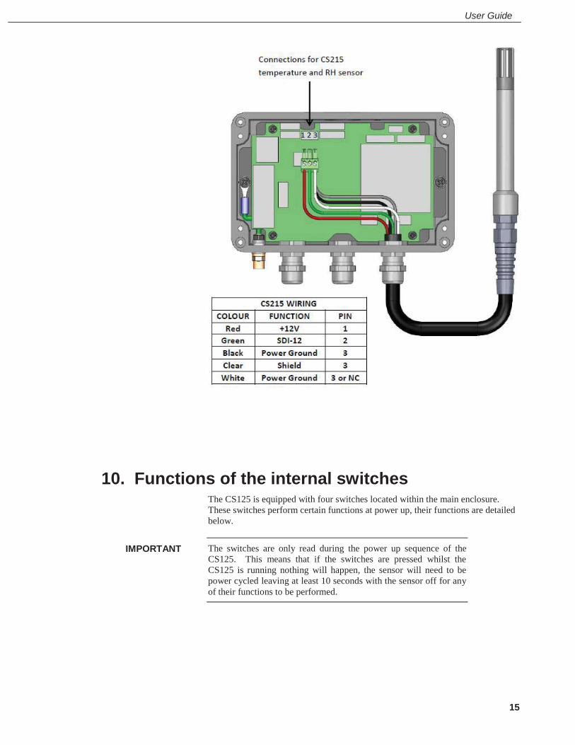
A CS215 temperature and RH sensor can be connected to the CS125. This is recommended as it will improve the performance of the CS125 in identifying precipitation and allows it to, for example, distinguish between mist and haze. Precipitation identification at temperatures close to freezing will be much improved by a CS215 and its use is highly recommended in regions where temperatures close to 0°C are common if information on precipitation type is important. It also allows RH information to be included in data messages.
If a CS215 is connected then the temperature used for assessment of precipitation type and included in data messages will come from the CS215 instead of the temperature sensor mounted in the cross arm.
The connections for the CS215 are shown below. The CS215 itself can be mounted in a Met20 screen on the same mast as the CS125. The screen can be mounted on the top section of an OSM1 optical mast below a CS125.
WMO – No. 8, 2.1.4.1 recommends temperature measurement at a height of between 1.2 and 2.0 m above ground. The screen should be below the height of the CS125 electronics box.
User Guide
15
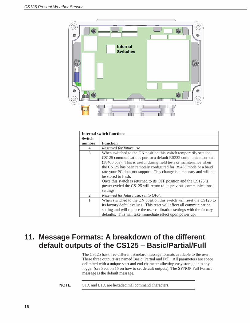
10. Functions of the internal switches The CS125 is equipped with four switches located within the main enclosure. These switches perform certain functions at power up, their functions are detailed below.
The switches are only read during the power up sequence of the CS125. This means that if the switches are pressed whilst the CS125 is running nothing will happen, the sensor will need to be power cycled leaving at least 10 seconds with the sensor off for any of their functions to be performed.
IMPORTANT
CS125 Present Weather Sensor
16
Internal switch functions Switch number
Function
4 Reserved for future use 3 When switched to the ON position this switch temporarily sets the
CS125 communications port to a default RS232 communication state (38400 bps). This is useful during field tests or maintenance when the CS125 has been remotely configured for RS485 mode or a baud rate your PC does not support. This change is temporary and will not be stored to flash. Once this switch is returned to its OFF position and the CS125 is power cycled the CS125 will return to its previous communications settings.
2 Reserved for future use, set to OFF. 1 When switched to the ON position this switch will reset the CS125 to
its factory default values. This reset will affect all communication setting and will replace the user calibration settings with the factory defaults. This will take immediate effect upon power up.
11. Message Formats: A breakdown of the different default outputs of the CS125 – Basic/Partial/Full
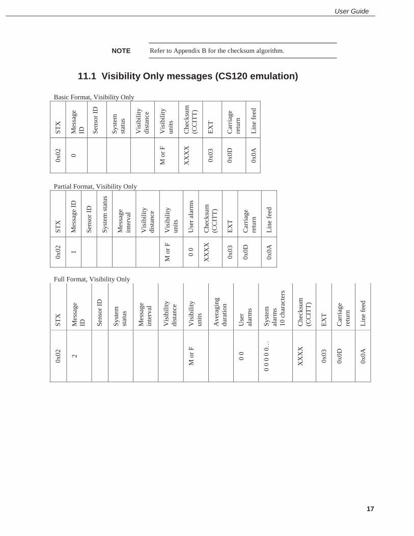
The CS125 has three different standard message formats available to the user. These three outputs are named Basic, Partial and Full. All parameters are space delimited with a unique start and end character allowing easy storage into any logger (see Section 15 on how to set default outputs). The SYNOP Full Format message is the default message.
STX and ETX are hexadecimal command characters. NOTE
User Guide
17
Refer to Appendix B for the checksum algorithm.
11.1 Visibility Only messages (CS120 emulation) Basic Format, Visibility Only
STX
Mes
sage
ID
Sens
or ID
Syst
em
stat
us
Vis
ibili
ty
dist
ance
Vis
ibili
ty
units
Che
cksu
m
(CC
ITT)
EXT
Car
riage
re
turn
Line
feed
0x02
0
M o
r F
XX
XX
0x03
0x0D
0x0A
Partial Format, Visibility Only
STX
Mes
sage
ID
Sens
or ID
Syst
em st
atus
Mes
sage
in
terv
al
Vis
ibili
ty
dist
ance
Vis
ibili
ty
units
Use
r ala
rms
Che
cksu
m
(CC
ITT)
EXT
Car
riage
re
turn
Line
feed
0x02
1
M o
r F
0 0
XX
XX
0x03
0x0D
0x0A
Full Format, Visibility Only
STX
Mes
sage
ID
Sens
or ID
Syst
em
stat
us
Mes
sage
in
terv
al
Vis
ibili
ty
dist
ance
Vis
ibili
ty
units
Ave
ragi
ng
dura
tion
Use
r al
arm
s
Syst
em
alar
ms
10 c
hara
cter
s
Che
cksu
m
(CC
ITT)
EXT
Car
riage
re
turn
Line
feed
0x02
2
M o
r F
0 0
0 0
0 0
0…
XX
XX
0x03
0x0D
0x0A
NOTE
CS125 Present Weather Sensor
18
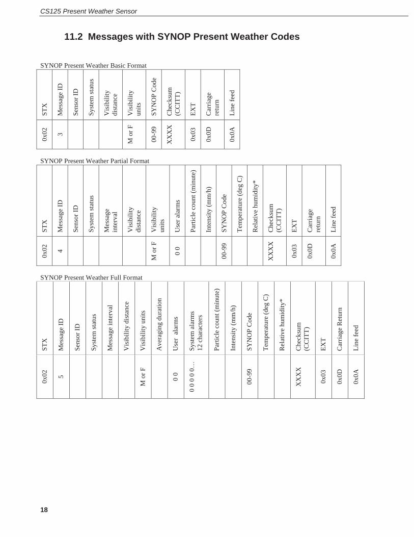
11.2 Messages with SYNOP Present Weather Codes SYNOP Present Weather Basic Format
STX
Mes
sage
ID
Sens
or ID
Syst
em st
atus
Vis
ibili
ty
dist
ance
Vis
ibili
ty
units
SYN
OP
Cod
e
Che
cksu
m
(CC
ITT)
EXT
Car
riage
re
turn
Line
feed
0x02
3
M o
r F
00-9
9
XX
XX
0x03
0x0D
0x0A
SYNOP Present Weather Partial Format
STX
Mes
sage
ID
Sens
or ID
Syst
em st
atus
Mes
sage
in
terv
al
Vis
ibili
ty
dist
ance
Vis
ibili
ty
units
Use
r ala
rms
Parti
cle
coun
t (m
inut
e)
Inte
nsity
(mm
/h)
SYN
OP
Cod
e
Tem
pera
ture
(deg
C)
Rel
ativ
e hu
mid
ity*
Che
cksu
m
(CC
ITT)
EXT
Car
riage
re
turn
Line
feed
0x02
4
M o
r F
0 0
00-9
9
XX
XX
0x03
0x0D
0x0A
SYNOP Present Weather Full Format
STX
Mes
sage
ID
Sens
or ID
Syst
em st
atus
Mes
sage
inte
rval
Vis
ibili
ty d
ista
nce
Vis
ibili
ty u
nits
Ave
ragi
ng d
urat
ion
Use
r al
arm
s
Syst
em a
larm
s 12
cha
ract
ers
Parti
cle
coun
t (m
inut
e)
Inte
nsity
(mm
/h)
SYN
OP
Cod
e
Tem
pera
ture
(deg
C)
Rel
ativ
e hu
mid
ity*
Che
cksu
m
(CC
ITT)
EXT
Car
riage
Ret
urn
Line
feed
0x02
5
M o
r F
0 0
0 0
0 0
0…
00-9
9
XX
XX
0x03
0x0D
0x0A

User Guide
19
11.3 Messages with METAR Present Weather Codes METAR Present Weather Basic Format
STX
Mes
sage
ID
Sens
or ID
Syst
em st
atus
Vis
ibili
ty
dist
ance
Vis
ibili
ty
units
MET
AR
Cod
e
Che
cksu
m
(CC
ITT)
EXT
Car
riage
re
turn
Line
feed
0x02
6
M o
r F
XX
XX
0x03
0x0D
0x0A
METAR Present Weather Partial Format
STX
Mes
sage
ID
Sens
or ID
Syst
em st
atus
Mes
sage
inte
rval
Vis
ibili
ty d
ista
nce
Vis
ibili
ty u
nits
Use
r ala
rms
Parti
cle
coun
t (m
inut
e)
Inte
nsity
(mm
/h)
SYN
OP
Cod
e
MET
AR
Cod
e
Tem
pera
ture
(deg
C)
Rel
ativ
e hu
mid
ity*
Che
cksu
m
(CC
ITT)
EXT
Car
riage
retu
rn
Line
feed
0x02
7
M o
r F
0 0
XX
XX
0x03
0x0D
0x0A
METAR Present Weather Full format
STX
Mes
sage
ID
Sens
or ID
Syst
em st
atus
Mes
sage
inte
rval
Vis
ibili
ty d
ista
nce
Vis
ibili
ty u
nits
Ave
ragi
ng d
urat
ion
Use
r al
arm
s
Syst
em a
larm
s 12
cha
ract
ers
Parti
cle
coun
t (m
inut
e)
Inte
nsity
(mm
/h)
SYN
OP
Cod
e
MET
AR
Cod
e
Tem
pera
ture
(deg
C)
Rel
ativ
e hu
mid
ity*
Che
cksu
m (C
CIT
T)
EXT
Car
riage
Ret
urn
Line
feed
0x02
8
M o
r F
0 0
0 0
0 0
0…
XX
XX
0x03
0x0D
0x0A
*Note: relative humidity is only available if a CS215 temperature and RH sensor is attached. If not this field is “-99”.
CS125 Present Weather Sensor
20
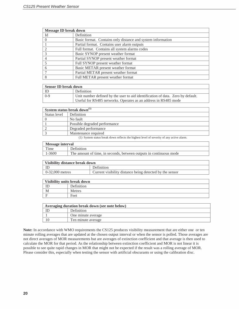
Message ID break down Id Definition 0 Basic format. Contains only distance and system information 1 Partial format. Contains user alarm outputs 2 Full format. Contains all system alarms codes 3 Basic SYNOP present weather format 4 Partial SYNOP present weather format 5 Full SYNOP present weather format 6 Basic METAR present weather format 7 Partial METAR present weather format 8 Full METAR present weather format
Sensor ID break down ID Definition 0-9 Unit number defined by the user to aid identification of data. Zero by default.
Useful for RS485 networks. Operates as an address in RS485 mode
System status break down(1) Status level Definition 0 No fault 1 Possible degraded performance 2 Degraded performance 3 Maintenance required
(1) System status break down reflects the highest level of severity of any active alarm.
Message interval Time Definition 1-3600 The amount of time, in seconds, between outputs in continuous mode
Visibility distance break down ID Definition 0-32,000 metres Current visibility distance being detected by the sensor
Visibility units break down ID Definition M Metres F Feet
Averaging duration break down (see note below) ID Definition 1 One minute average 10 Ten minute average
Note: In accordance with WMO requirements the CS125 produces visibility measurement that are either one or ten minute rolling averages that are updated at the chosen output interval or when the sensor is polled. Those averages are not direct averages of MOR measurements but are averages of extinction coefficient and that average is then used to calculate the MOR for that period. As the relationship between extinction coefficient and MOR is not linear it is possible to see quite rapid changes in MOR that might not be expected if the result was a rolling average of MOR. Please consider this, especially when testing the sensor with artificial obscurants or using the calibration disc.
User Guide
21
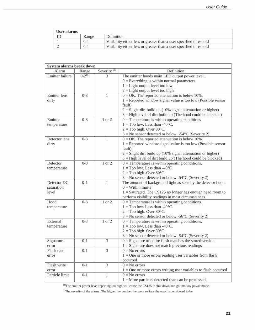
User alarms ID Range Definition 1 0-1 Visibility either less or greater than a user specified threshold 2 0-1 Visibility either less or greater than a user specified threshold
System alarms break down Alarm Range Severity (2) Definition
Emitter failure 0-2(1) 3 The emitter hoods main LED output power level. 0 = Everything is within normal parameters 1 = Light output level too low 2 = Light output level too high
Emitter lens dirty
0-3 1 0 = OK. The reported attenuation is below 10%. 1 = Reported window signal value is too low (Possible sensor fault) 2 = Slight dirt build up (10% signal attenuation or higher) 3 = High level of dirt build up (The hood could be blocked)
Emitter temperature
0-3 1 or 2 0 = Temperature is within operating conditions 1 = Too low. Less than -40°C. 2 = Too high. Over 80°C. 3 = No sensor detected or below -54°C (Severity 2)
Detector lens dirty
0-3 1 0 = OK. The reported attenuation is below 10%. 1 = Reported window signal value is too low (Possible sensor fault) 2 = Slight dirt build up (10% signal attenuation or higher) 3 = High level of dirt build up (The hood could be blocked)
Detector temperature
0-3 1 or 2 0 = Temperature is within operating conditions. 1 = Too low. Less than -40°C. 2 = Too high. Over 80°C. 3 = No sensor detected or below -54°C (Severity 2)
Detector DC saturation level
0-1 1 The amount of background light as seen by the detector hood. 0 = Within limits 1 = Saturated. The CS125 no longer has enough head room to perform visibility readings in most circumstances.
Hood temperature
0-3 1 or 2 0 = Temperature is within operating conditions. 1 = Too low. Less than -40°C. 2 = Too high. Over 80°C. 3 = No sensor detected or below -56°C (Severity 2)
External temperature
0-3 1 or 2 0 = Temperature is within operating conditions. 1 = Too low. Less than -40°C. 2 = Too high. Over 80°C. 3 = No sensor detected or below -54°C (Severity 2)
Signature error
0-1 3 0 = Signature of entire flash matches the stored version 1 = Signature does not match previous readings
Flash read error
0-1 3 0 = No errors 1 = One or more errors reading user variables from flash occurred
Flash write error
0-1 3 0 = No errors 1 = One or more errors writing user variables to flash occurred
Particle limit 0-1 1 0 = No errors 1 = More particles detected than can be processed.
(1)The emitter power level reporting too high will cause the CS125 to shut down and go into low power mode. (2)The severity of the alarm. The higher the number the more serious the error is considered to be.
CS125 Present Weather Sensor
22
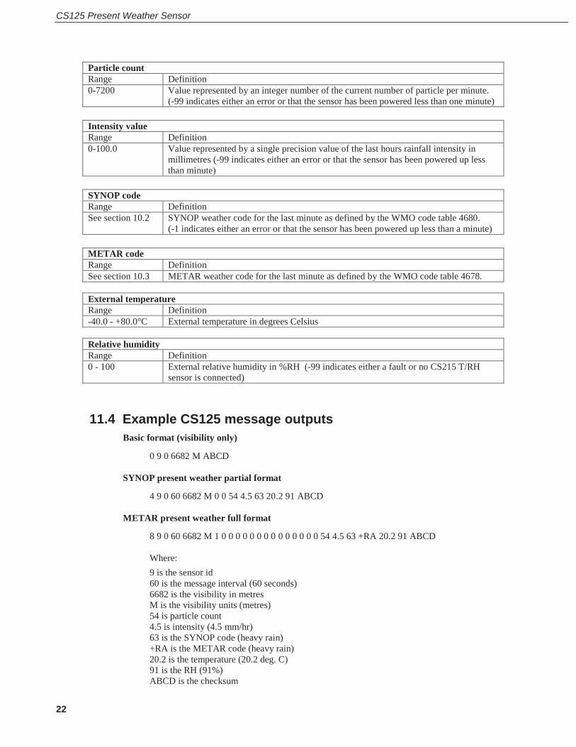
Particle count Range Definition 0-7200 Value represented by an integer number of the current number of particle per minute.
(-99 indicates either an error or that the sensor has been powered less than one minute)
Intensity value Range Definition 0-100.0 Value represented by a single precision value of the last hours rainfall intensity in
millimetres (-99 indicates either an error or that the sensor has been powered up less than minute)
SYNOP code Range Definition See section 10.2 SYNOP weather code for the last minute as defined by the WMO code table 4680.
(-1 indicates either an error or that the sensor has been powered up less than a minute)
METAR code Range Definition See section 10.3 METAR weather code for the last minute as defined by the WMO code table 4678.
External temperature Range Definition -40.0 - +80.0°C External temperature in degrees Celsius
Relative humidity Range Definition 0 - 100 External relative humidity in %RH (-99 indicates either a fault or no CS215 T/RH
sensor is connected)
11.4 Example CS125 message outputs Basic format (visibility only)
0 9 0 6682 M ABCD
SYNOP present weather partial format
4 9 0 60 6682 M 0 0 54 4.5 63 20.2 91 ABCD
METAR present weather full format
8 9 0 60 6682 M 1 0 0 0 0 0 0 0 0 0 0 0 0 0 0 54 4.5 63 +RA 20.2 91 ABCD
Where: 9 is the sensor id 60 is the message interval (60 seconds) 6682 is the visibility in metres M is the visibility units (metres) 54 is particle count 4.5 is intensity (4.5 mm/hr) 63 is the SYNOP code (heavy rain) +RA is the METAR code (heavy rain) 20.2 is the temperature (20.2 deg. C) 91 is the RH (91%) ABCD is the checksum

User Guide
23
11.5 SYNOP Codes produced by the CS125 The following SYNOP codes from WMO table 4680 can be output by the CS125. 00 No significant weather observed 04 Haze or smoke, or dust in suspension in the air, visibility equal to, or greater
than, 1 km 05 Haze or smoke, or dust in suspension in the air, visibility less than 1 km Note: Codes 04 and 05 will only be returned if a CS215 is present to provide relative humidity, otherwise they will default to mist (10) or fog (20, 30 or 35).
10 Mist Code figures 20–26 are used to report precipitation, fog (or ice fog) or thunderstorm at the station during the preceding hour but not at the time of observation.
20 Fog 21 PRECIPITATION 22 Drizzle (not freezing) or snow grains 23 Rain (not freezing) 24 Snow 25 Freezing drizzle or freezing rain 30 FOG 35 Fog, depositing rime 40 PRECIPITATION 51 Drizzle, not freezing, slight 52 Drizzle, not freezing, moderate 53 Drizzle, not freezing, heavy 54 Drizzle, freezing, slight 55 Drizzle, freezing, moderate 56 Drizzle, freezing, heavy 57 Drizzle and rain, slight 58 Drizzle and rain, moderate or heavy 61 Rain, not freezing, slight 62 Rain, not freezing, moderate 63 Rain, not freezing, heavy 64 Rain, freezing, slight 65 Rain, freezing, moderate 66 Rain, freezing, heavy 67 Rain (or drizzle) and snow, slight 68 Rain (or drizzle) and snow, moderate or heavy 71 Snow, slight 72 Snow, moderate 73 Snow, heavy

CS125 Present Weather Sensor
24
11.6 METAR Codes produced by the CS125 The following METAR codes from WMO table 4678 can be output by the CS125. UP Unidentified precipitation HZ Haze BR Mist FG Fog DZ Drizzle RA Rain SN Snow SG Snow grains PL Ice pellets Notes: HZ will only be reported if a CS215 is connected to allow relative humidity information to be available. FZ (freezing) may be added as a descriptor in front of BR, FG, DZ and RZ Intensity qualifiers, ‘-‘ for light, ‘+’ for heavy, may be added in front of DZ, RA, SN, SG and PL Combinations, for example RASN for rain and snow can be reported.
12. Interface methods – Device Configuration Utility/Command line/Menu
The CS125 can be setup and controlled in one of three ways.
The first method is by using Campbell Scientific’s Device Configuration Utility Software (DevConfig) which is included with each delivery on the manuals/ resource disk. This software allows an easy menu driven interface for configuring the CS125 on any Microsoft™ based personal computer. All settings can be accessed using this program.
The program includes online help instructions that describe its general use with the CS125 and also how to load an operating system.
The Device Configurator can also be used as a terminal emulator to use the built-in menu system of the CS125 and to access its calibration menu.
The second method is by using the command line interface where discrete commands are sent without response from the sensor. This would be the preferred method of setting up a CS125 if it was connected to a logger for instance. The configuration setting commands can be sent via a logger to the CS125 removing the need for a local PC to set up the unit.
The third method is by using the simple menu interface built into the CS125 communicating via RS232 or RS485, using a terminal emulator program. This menu system gives access to the more common settings.
All three of these methods use the CS125s serial port A to communicate with the sensor. Configuration cable part number 010817, described in section 8.1 can be used.

User Guide
25
12.1 Configuring a PC for talking to the CS125 Described below is the procedure for setting up communications using a terminal emulator program. The terminal emulators built into many Campbell Scientific software products can also be used.
The following settings should then be used by default:
Bits per second: 38400 Data bits: 8 Parity: none Stop bits: 1 Flow control: none
Ensure that if the baud rate of the unit has been adjusted and then the corresponding bits per second value is entered in the port settings of the terminal emulator. The CS125 should now be ready to accept commands.
It is possible to set the CS125 into the default communication state via one of the internal switches on the CS125 main board. See section 9.
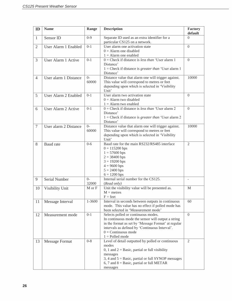
13. Definition of the variables that can be set by the user on the CS125
Both DevConfig and the command line interface can access all the user configurable variables within the CS125. The acceptable range and the identification number for these variables are listed below along with a short description.
CS125 Present Weather Sensor
26
ID Name Range Description Factory default
1 Sensor ID 0-9 Separate ID used as an extra identifier for a particular CS125 on a network.
0
2 User Alarm 1 Enabled 0-1 User alarm one activation state 0 = Alarm one disabled 1 = Alarm one enabled
0
3 User Alarm 1 Active 0-1 0 = Check if distance is less than ‘User alarm 1 Distance’ 1 = Check if distance is greater than ‘User alarm 1 Distance’
0
4 User alarm 1 Distance 0-60000
Distance value that alarm one will trigger against. This value will correspond to metres or feet depending upon which is selected in ‘Visibility Unit’
10000
5 User Alarm 2 Enabled 0-1 User alarm two activation state 0 = Alarm two disabled 1 = Alarm two enabled
0
6 User Alarm 2 Active 0-1 0 = Check if distance is less than ‘User alarm 2 Distance’ 1 = Check if distance is greater than ‘User alarm 2 Distance’
0
7 User alarm 2 Distance 0-60000
Distance value that alarm one will trigger against. This value will correspond to metres or feet depending upon which is selected in ‘Visibility Unit’
10000
8 Baud rate 0-6 Baud rate for the main RS232/RS485 interface 0 = 115200 bps 1 = 57600 bps 2 = 38400 bps 3 = 19200 bps 4 = 9600 bps 5 = 2400 bps 6 = 1200 bps
2
9 Serial Number 0-32000
Internal serial number for the CS125. (Read only)
-
10 Visibility Unit M or F Unit the visibility value will be presented as. M = metres F = feet
M
11 Message Interval 1-3600 Interval in seconds between outputs in continuous mode. This value has no effect if polled mode has been selected in ‘Measurement mode’
60
12 Measurement mode 0-1 Selects polled or continuous modes. In continuous mode the sensor will output a string in the format as set by ‘Message Format’ at regular intervals as defined by ‘Continuous Interval’. 0 = Continuous mode 1 = Polled mode
0
13 Message Format 0-8 Level of detail outputted by polled or continuous modes 0, 1 and 2 = Basic, partial or full visibility messages 3, 4 and 5 = Basic, partial or full SYNOP messages 6, 7 and 8 = Basic, partial or full METAR messages
2

User Guide
27
14 Serial port protocol 0-1 Selects the physical serial interface 0 = RS232 mode 1 = RS485 mode
0
15 Averaging period 1 or 10 The period of time that the visibility value should be averaged over. Either one minute or ten.
1
16 Sample timing 1-60 Used to define the time interval between sampling the volume. It is recommended that this value is left at one except when very low power demands are needed. For example: 1 = Sample every second 2 = Sample one second in every two 3 = Sample one second in every three etc.
1
17 Dew heater override 0-1 0 = Allow the CS125 to automatically control the dew heaters 1 = Turn the dew heaters off
0
18 Hood heater override(1) 0-1 0 = Allow the CS125 to automatically control the hood heaters 1 = Turn the hood heaters off
0
19 Dirty window compensation
0-1 0 = No compensation applied 1 = Compensation for dirt on lenses applied. The CS125 will compensate for up to 10% signal loss due to dirt per lens.
0
20 Use CRC 0-1 0 = Disable command line CRC checking(2) 1 = Enable command line CRC checking Note: this does not affect communications via DevConfig or terminal emulator.
0
21 Sensor power down voltage
7-30 PSU Input voltage level below which the CS125 will enter low power mode. This is usually used to protect batteries.
7.0
22 Relative humidity threshold
1-99 Threshold at which the CS125 will define obscuration as liquid or dry if a CS215 is fitted.
80%
(1) Hood heater override needs to be set to `1’ (off) when either no hood heaters are installed or the hood heaters have no power connected to them. This will save power as the relay is not enabled at low temperatures in this mode. (2) If disabled the sensor does not check the validity of received data against the checksum sent. It is, however, recommended that checksum checking is enabled to remove any chance of the CS125 being configured incorrectly by accident.
14. Command line mode The command line interface is broken down into three major commands. These are GET, SET and POLL. The GET command is used to request all current user settable values from the CS125. The SET commands sets user settable values and the POLL command is used to request the current visibility and/or alarm conditions from the sensor.
The CS125 can be configured to expect any commands sent to it to include a valid checksum. For simple commands, e.g. GET and POLL, fixed value checksums can be used (see the example programs). For more complex SET commands the checksum needs to be calculated (see Appendix B). The use of the checksum is disabled by default. It is recommended that the checksum functionality is enabled where possible, especially when long cable runs are used, or in electronically noisy environments.
CS125 Present Weather Sensor
28
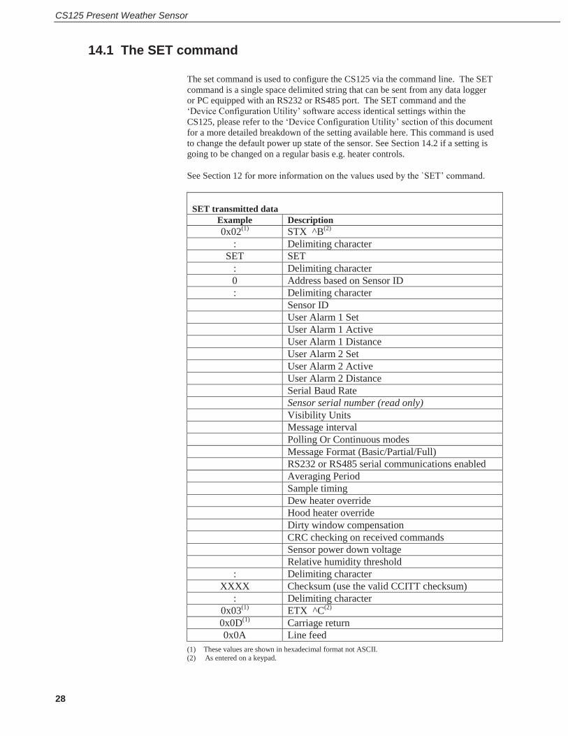
14.1 The SET command The set command is used to configure the CS125 via the command line. The SET command is a single space delimited string that can be sent from any data logger or PC equipped with an RS232 or RS485 port. The SET command and the ‘Device Configuration Utility’ software access identical settings within the CS125, please refer to the ‘Device Configuration Utility’ section of this document for a more detailed breakdown of the setting available here. This command is used to change the default power up state of the sensor. See Section 14.2 if a setting is going to be changed on a regular basis e.g. heater controls.
See Section 12 for more information on the values used by the `SET’ command.
SET transmitted data
Example Description 0x02(1) STX ^B(2)
: Delimiting character SET SET
: Delimiting character 0 Address based on Sensor ID : Delimiting character Sensor ID User Alarm 1 Set User Alarm 1 Active User Alarm 1 Distance User Alarm 2 Set User Alarm 2 Active User Alarm 2 Distance Serial Baud Rate Sensor serial number (read only) Visibility Units Message interval Polling Or Continuous modes Message Format (Basic/Partial/Full) RS232 or RS485 serial communications enabled Averaging Period Sample timing Dew heater override Hood heater override Dirty window compensation CRC checking on received commands Sensor power down voltage Relative humidity threshold : Delimiting character
XXXX Checksum (use the valid CCITT checksum) : Delimiting character
0x03(1) ETX ^C(2) 0x0D(1) Carriage return 0x0A Line feed
(1) These values are shown in hexadecimal format not ASCII. (2) As entered on a keypad.
User Guide
29
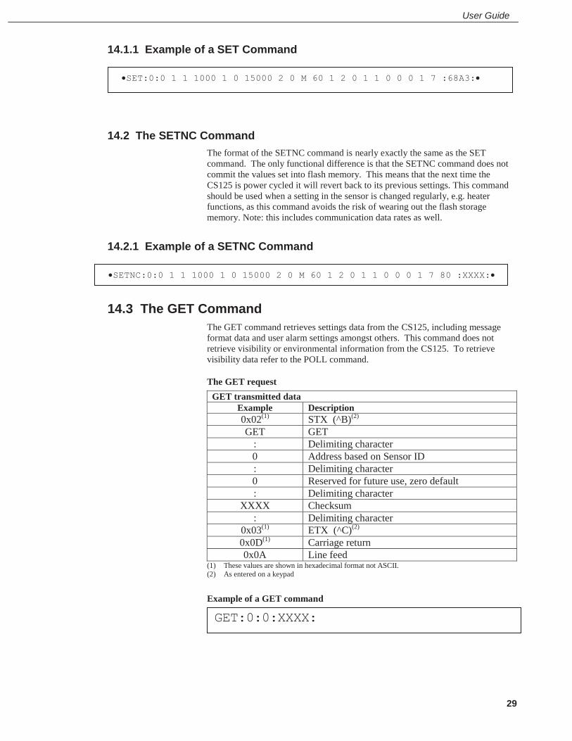
14.1.1 Example of a SET Command
14.2 The SETNC Command The format of the SETNC command is nearly exactly the same as the SET command. The only functional difference is that the SETNC command does not commit the values set into flash memory. This means that the next time the CS125 is power cycled it will revert back to its previous settings. This command should be used when a setting in the sensor is changed regularly, e.g. heater functions, as this command avoids the risk of wearing out the flash storage memory. Note: this includes communication data rates as well.
14.2.1 Example of a SETNC Command
14.3 The GET Command The GET command retrieves settings data from the CS125, including message format data and user alarm settings amongst others. This command does not retrieve visibility or environmental information from the CS125. To retrieve visibility data refer to the POLL command.
The GET request GET transmitted data
Example Description 0x02(1) STX (^B)(2) GET GET
: Delimiting character 0 Address based on Sensor ID : Delimiting character 0 Reserved for future use, zero default : Delimiting character
XXXX Checksum : Delimiting character
0x03(1) ETX (^C)(2) 0x0D(1) Carriage return 0x0A Line feed
(1) These values are shown in hexadecimal format not ASCII. (2) As entered on a keypad Example of a GET command
SETNC:0:0 1 1 1000 1 0 15000 2 0 M 60 1 2 0 1 1 0 0 0 1 7 80 :XXXX:
SET:0:0 1 1 1000 1 0 15000 2 0 M 60 1 2 0 1 1 0 0 0 1 7 :68A3:
GET:0:0:XXXX:

CS125 Present Weather Sensor
30
Example data returned by the GET command – See Section 12 for more information on values returned by the `GET’ command
GET returned data Example Description 0x02(1) STX
Sensor ID User Alarm 1 Set User Alarm 1 Active User Alarm 1 Distance User Alarm 2 Set User Alarm 2 Active User Alarm 2 Distance Serial Baud Rate Sensor serial number (read only) Visibility Units Message interval Polling Or Continuous modes Message Format (Basic/Partial/Full) RS232 or RS485 serial communications enabled Averaging Period Sample timing Dew heater override Hood heater override Dirty window compensation CRC checking on received commands Sensor power down voltage 7.0 Relative humidity threshold : Delimiting character
XXXX Checksum : Delimiting character
0x04(1) EOT 0x0D(1) Carriage return 0x0A Line feed
(1) These values are shown in hexadecimal format not ASCII.
Example of a GET returned data
0 0 0 10000 0 0 10000 2 1009 M 30 0 2 1 1 1 0 0 0 1 11.5 D4FD
Explanation: -
Sensor ID = 0
User Alarm 1 not set
User Alarm 1 not active
User Alarm 1 distance = 10000 metres
User Alarm 2 not set
User Alarm 2 not active

User Guide
31
User Alarm 2 distance = 10000 metres
Serial baud rate 2 (=38400Bd)
Serial number = 1009
Visibility Units = M
Continuous mode output interval = 30 seconds
Polling mode = 0 (continuous mode)
Message format = 2 (full message)
RS232 or RS485 serial communications = 1 ( RS485)
Averaging period = 1 minute
Sample timing = 1 sample per second
Dew heater override = 0 (CS125 will automatically control the dew heaters)
Hood heater override = 0 (CS125 will automatically control the hood heaters)
Dirty window compensation = 0 (dirty window compensation off)
CRC checking on received commands = 1 (CRC checking enabled)
Sensor power down voltage = 11.5V
Checksum = D4FD
14.4 The POLL command – Polling the CS125 The POLL command requests the current visibility and/or alarm conditions from the CS125. The output format of this command depends on how the CS125 is configured using the SET command or the menu interfaces. The POLL request
POLL transmitted data Example Description 0x02(1) STX, ^B(2) POLL POLL
: Delimiting character 0 Address based on Sensor ID : Delimiting character 0 Reserved for future use, zero default : Delimiting character
XXXX Checksum(3) : Delimiting character
0x03(1) ETX, ^C(2) 0x0D(1) Carriage return 0x0A Line feed
(1) These values are shown in hexadecimal format not ASCII. (2) As entered on a keypad. (3) Not case sensitive.

CS125 Present Weather Sensor
32
Example of a POLL request
The maximum response time to a poll command is 100 ms.
If the setting to check the checksum on received commands is enabled the checksum varies with the Sensor ID value.
15. Entering the CS125 menu system The user can enter the menu system by typing ‘open id’ into their terminal program then pressing the return key on their keyboard. The id corresponds to the sensor ID number. The Sensor ID number can be in the range of 0 to 9. The factory default is 0.
The ‘open 0’ command is not normally echoed. The terminal menu only gives access to more common settings.
The following text should now be displayed:
The displayed options are accessed simply by typing the corresponding number then pressing return. No changes will take effect until you `save and exit’. The exception to this is the calibration menu, but you will be informed before any changes are made.
The displayed options are accessed simply by typing the corresponding number then pressing return. No changes will take effect until you `Exit and Save’. The exception to this is the calibration menu, but you will be informed before any changes are made.
Typing `1’ opens the message menu containing settings relating to the CS125’s outputs.
NOTE
NOTE
POLL:0:0:XXXX:
WELCOME TO THE CAMPBELL SCIENTIFIC LTD CS125 SETUP MENU ID 0 S/N 1003 (1) Message output menu (2) User alarm menu (3) Calibrate CS125 (4) Communications setup (5) System configuration
(9) Exit and save (0) Exit and don't save ->

User Guide
33
Menu 1: The message output menu
For example, typing `2’ will toggle the units through the options `METRES’ and `FEET’ and typing `4’ will allow the message interval to be entered.
Option (2) allows the User Alarms to be set, again by toggling through options or changing values.
Menu 2: The user alarm menu
Menu 2: The user alarm menu. Sub menu 2: Alarm two activation level (Option 6)
Option (3) is the calibration menu Menu 3: The calibration menu
CS125 ALARM - MENU 2 ID 0 S/N 1009 (1) Toggle user alarm one: DISABLED (2) Toggle alarm one threshold: LESS THAN (3) Set new user alarm one activation point: 10000 m (4) Toggle user alarm two: DISABLED (5) Toggle alarm two threshold: LESS THAN (6) Set new user alarm two activation point: 10000 m
(9) Refresh (0) Return to main menu ->
CS125 CALIBRATION - MENU 3 ID 0 S/N 1003 (1) Perform calibration (2) Restore the factory calibration (3) Perform dirty windows zero offset calibration (4) Restore dirty windows factory calibration (9) Refresh (0) Return to main menu
->
CS125 MESSAGE - MENU 1 ID 0 S/N 1009 (1) Toggle message format:FULL (2) Toggle units:METRES (3) Toggle polled or continuous mode:CONTINUOUS (4) Set continuous mode output interval:6 second(s) (5) Toggle output averaging period: 1 minute(s) (6) Sampling interval:1 second(s) (9) Refresh (0) Return to main menu

CS125 Present Weather Sensor
34
Consult the ‘calibration’ section of this manual for information on how to calibrate the CS125 present weather sensor.
Once a calibration is finished changes are immediate, but factory calibrations can be restored if needed using Option `(2)’ in the calibration menu. The disk constants however remain as the last disk used.
Option (4) gives the systems information menu containing useful information such as temperature and system alarms.
Menu 4: The system information menu
If either of the dirty window alarms are set it is recommended you follow the cleaning section of this manual (Section 18).
If there is a flash error or signature error it is recommended that you contact Campbell Scientific.
NOTE
CS125 INFORMATION - MENU 4 ID 0 S/N 1003 OS version: 007646v1
Alarm Value
- Last visibility reading: - 3258M - Overall system status: 0 No faults - Emitter dirty window alarm: 0 0% - Emitter internal temperature: 0 38.4 - Detector dirty window alarm: 0 0% - Detector internal temperature: 0 31.0 - Detector DC light saturation: 0 - - Hood heater temperature: 0 25.6 - CS125 Calibrator Serial No: - 1000 - CS125 Calibrator Constant: - 30.5 - Calibration value Fac offset: - -0.026 - Calibration value Fac scale: - 0.02682 - Calibration value Cal offset: - -0.026 - Calibration value Cal scale: - 0.02682 - Signature fault: 0 - - Flash write errors: 0 0 - Flash read errors: 0 0 - Supply voltage: <7.0V 11.3V - Aux supply voltages: +5V=5.0 -5V=-5.1
+6V=5.9 - External temperature: 0 26.4 - Present weather mode enabled (8) Get debug (9) Refresh (0) Return to main menu ->
User Guide
35
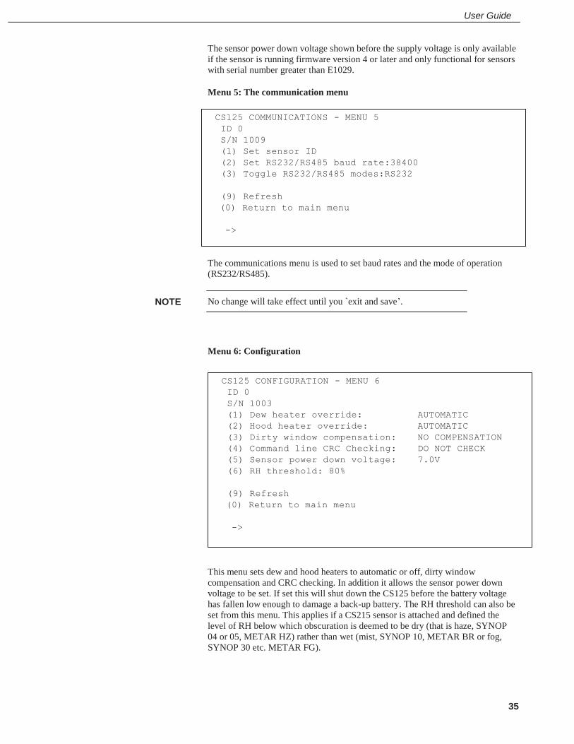
The sensor power down voltage shown before the supply voltage is only available if the sensor is running firmware version 4 or later and only functional for sensors with serial number greater than E1029.
Menu 5: The communication menu
The communications menu is used to set baud rates and the mode of operation (RS232/RS485).
No change will take effect until you `exit and save’.
Menu 6: Configuration
This menu sets dew and hood heaters to automatic or off, dirty window compensation and CRC checking. In addition it allows the sensor power down voltage to be set. If set this will shut down the CS125 before the battery voltage has fallen low enough to damage a back-up battery. The RH threshold can also be set from this menu. This applies if a CS215 sensor is attached and defined the level of RH below which obscuration is deemed to be dry (that is haze, SYNOP 04 or 05, METAR HZ) rather than wet (mist, SYNOP 10, METAR BR or fog, SYNOP 30 etc. METAR FG).
NOTE
CS125 COMMUNICATIONS - MENU 5 ID 0 S/N 1009 (1) Set sensor ID (2) Set RS232/RS485 baud rate:38400 (3) Toggle RS232/RS485 modes:RS232 (9) Refresh
(0) Return to main menu ->
CS125 CONFIGURATION - MENU 6 ID 0 S/N 1003 (1) Dew heater override: AUTOMATIC (2) Hood heater override: AUTOMATIC (3) Dirty window compensation: NO COMPENSATION (4) Command line CRC Checking: DO NOT CHECK (5) Sensor power down voltage: 7.0V (6) RH threshold: 80% (9) Refresh
(0) Return to main menu ->

CS125 Present Weather Sensor
36
Menu 9 and 0: Exiting the menu system
Options `9’ and `0’ exit from the menu system. Note that typing `0’ will lose all changes made including communications settings.
16. Calibrating the CS125 The CS125 can be checked and adjusted using the optional CS125 calibrator part number 010816. The calibration must be run using the onboard menu system. If you have Campbell Scientific’s Device configuration program a terminal emulation screen is provided in the CS125 screens to let you access this function. To perform the calibration you will need a CS125 calibrator disk and a computer with a standard serial port compatible with the CS125. If your CS125 is not currently configured for RS232 communications you can set the internal switch, switch three, to temporarily set the sensor to RS232 mode 38400bps. If the sensor is already set in RS232 mode it should not be necessary to change any internal switches. (See Section 10 for more information on the CS125 internal switches.)
The test should ideally be performed in the following conditions:
Ambient temperature should be 20ºC +/-10ºC
The local visibility should be approximately 10,000 metres or higher.
The system is self-regulating. However, it is recommended that the CS125 is calibrated at least every two years.
The calibration is performed from menu item 3 on the main terminal screen. Please refer to the menu section (Section 13) of this manual for further information on how to access this menu.
Once you have selected menu item 3 you should be presented with the following screen.
Select option 1 to start the calibration. You will then be asked to confirm that you would like to perform a calibration. Please note, once you have entered yes at this point you will not be able to exit until the test is complete. However, power cycling the unit at this point will have no adverse effect on the sensor.
CS125 CALIBRATION - MENU 3 ID 0 S/N 1009 (1) Perform calibration (2) Restore the factory calibration (9) Refresh (0) Return to main menu
CAMPBELL SCIENTIFIC LTD CS125 menu exited.

User Guide
37
Once you have started the tests you will be asked for the CS125 calibrator serial number and coefficient with a confirmation at each step giving you the chance to correct typing mistakes.
When asked for confirmation you do not need to press return after you type ‘y’.
CS120/125 calibrator serial number and coefficients will be within this area.
When you have entered the calibrator information the sensor will wait for you to place the foam bungs into the sensor hoods. The bungs are designed to block all light from the outside reaching inside the head. Place one bung into each hood. If either of the bungs are damaged or appear to have any gaps around the edge please contact Campbell Scientific.
NOTE
Starting calibration. Input the CS125 calibrator serial number ->12345 Is 12345 correct? (Y/N)? Input the CS125 calibrator constant ->10000 Is 10000 correct? (Y/N)?
Place one calibration bung into each hood, then press any key.
Do you want to perform a calibration Y/N?

CS125 Present Weather Sensor
38
This part of the test will take approximately two minutes. Every ten seconds a dot should appear indicating that the test is progressing as normal.
Remove the bungs once the sensor instructs you to. Place the CS125 calibrator into the volume by fastening it to the central mounting point.
At this stage it is advisable to clean the lenses. Refer to Section 18 `Cleaning’ for more information. A simple visual check may be enough to confirm the lenses are clean.
NOTE
Starting dark level calibration. This test will take approximately two minutes
Dark level test complete. Please remove the bungs. Now place the CS125 calibrator into the sampling volume. Press any key once this is done.
User Guide
39
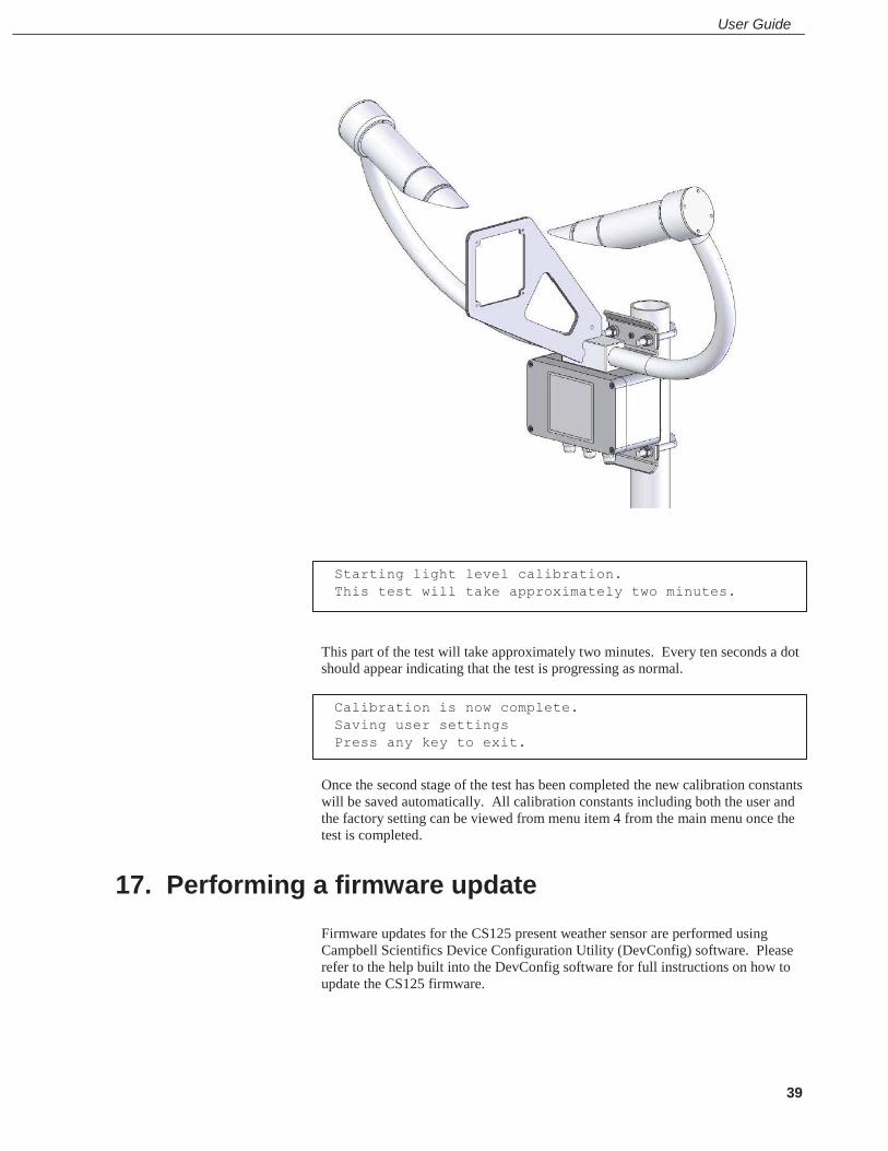
This part of the test will take approximately two minutes. Every ten seconds a dot should appear indicating that the test is progressing as normal.
Once the second stage of the test has been completed the new calibration constants will be saved automatically. All calibration constants including both the user and the factory setting can be viewed from menu item 4 from the main menu once the test is completed.
17. Performing a firmware update Firmware updates for the CS125 present weather sensor are performed using Campbell Scientifics Device Configuration Utility (DevConfig) software. Please refer to the help built into the DevConfig software for full instructions on how to update the CS125 firmware.
Starting light level calibration. This test will take approximately two minutes.
Calibration is now complete. Saving user settings Press any key to exit.
CS125 Present Weather Sensor
40
18. Cleaning The CS125 present weather sensor is a robust instrument that will provide years of uninterrupted weather monitoring. Calibration of the instrument is carried out at the factory and can be redone easily on site with the optional CS125 calibrator or carried out by Campbell Scientific if required. Only general cleaning of the lenses is required to keep the sensor working efficiently.
Cleaning of the CS125 will be required from time to time to ensure that the lenses are free from contaminants. The frequency of required cleaning depends on the exposure of the instrument to such contaminants. This will vary depending on the site location. The CS125 is capable of self diagnosing dirty lenses and will indicate in its output when the lenses are contaminated to such a degree that its visibility measurements may be affected.
A lower level of contamination than is detected by the dirty window alarms, can affect the visibility measurements. The sensor can be configured to attempt to make a correction for contamination although the accuracy of that correction depends on the `type of dirt’.
We suggest 6 monthly intervals for locations not prone to contaminants and monthly intervals for those prone to contamination (roadside or airport use). In some cases more frequent cleaning may be required where there are high levels of contaminants and high dependency on the instrument output.
If the lenses require cleaning, it is very important that only a proper lens cloth or lens tissue be used. The use of inappropriate materials to clean the lenses can permanently damage or reduce the effectiveness of the lenses leading to errors in measurement of precipitation and visibility.
It is advisable to use an air duster to blow any loose dust and dirt from the lenses as a first step. Using a lint free lens cloth or lens tissue impregnated with a small amount of isopropyl alcohol solvent clean the lens surface by dragging the cloth across the lens surface being careful not to apply excessive pressure.
Excessive pressure may lead to some types of contaminant scratching the lens surface. Over time such scratches can lead to reduced sensor accuracy.
Spiders webs and certain `fluffy’ seeds which get lodged in the optical path can lead to the sensor permanently giving low readings as they can emulate precipitation. Cleaning the contamination away with a duster will return the sensor to normal operation.
If spiders are a persistent problem, using some carefully applied insecticide can deter them.
NOTE
CAUTION
NOTE

User Guide
41
19. Lubricating the enclosure screws The CS125 enclosure screws should be lubricated with a suitable anti-seize grease (often copper loaded) to protect the threads from corrosion. This should be reapplied when resealing the enclosure at regular intervals, normally after replacing the desiccant. This is of particular importance if using the sensor in corrosive or salt laden atmospheres.
20. Desiccant Two bags of desiccant are supplied. One is inside the enclosure, the other is separate and sealed in a plastic bag. Desiccant use depends on your application but for use in typical temperature conditions one bag is sufficient for a twelve month period. The desiccant should be placed inside the enclosure taking care that it is not trapped between the lid and the enclosure when the lid is replaced.
The second bag of desiccant should be kept in the plastic shipping bag as a replacement for when the initial bag needs to be dried out. The bags can be rotated in this way many times. Desiccant bags can be dried out by the following method:
1. Arrange the bags on a wire tray in a single layer to allow for adequate air flow around the bags during the drying process. The oven’s inside temperature should be room or ambient temperature (25°C - 30°C). A convection, circulating, forced air type oven is recommended for this regeneration process. Seal failures may occur if any other type of heating unit or appliance is used.
2. When placed in a forced air, circulating air, or convection oven, allow a minimum of 4 to 5 cm of air space between the top of the bags and the next metal tray above the bags. If placed in a radiating exposed infrared element type oven, shield the bags from direct exposure to the heating element, giving the closest bags a minimum of 40 cm clearance from the heat shield. Excessive surface film temperature due to infrared radiation will cause the Tyvek material to melt and/or the seals to fail. Seal failure may also occur if the temperature is allowed to increase rapidly. This is due to the fact that the water vapour is not given sufficient time to diffuse through the Tyvek material, thus creating internal pressure within the bag, resulting in a seal rupture. Temperature should not increase faster than 0.1°C to 0.3°C per minute.
3. Set the temperature of the oven to 118°C, and allow the bags of desiccant to reach equilibrium temperature.
Tyvek has a melting temperature of 121°C - 127°C.
(NON MIL-D-3464E activation or reactivation of both silica gel and Bentonite clay can be achieved at temperatures of 104°C).
4. Desiccant bags should be allowed to remain in the oven at the assigned temperature for 24 hours. At the end of this period, the bags should be immediately removed and placed in a desiccators jar or dry (0% relative humidity) air tight container for cooling. If this procedure is not followed precisely, any water vapour driven off during reactivation may be re-adsorbed during cooling and/or handling.
CAUTION

CS125 Present Weather Sensor
42
5. After the bags of desiccant have been allowed to cool in an airtight desiccator, they may be removed and placed in either an appropriate type polyliner tightly sealed to prevent moisture adsorption, or a container that prevents moisture from coming into contact with the regenerated desiccant. Some care should be taken when re-activating desiccant bags. If heated in an oven which is too hot, the bags may burst. If in any doubt, we recommend purchasing new desiccant packs instead of oven drying. Failure to use or exchange the desiccant may lead to condensation inside the enclosure. Not only will this lead to corrupted data but, in the long term, can also cause corrosion which is expensive to repair.

A-1
Appendix A. CS125 block diagram
850nm Emitter
Photo-detector
Transimpedance amplifier
Power level + Driver circuitry
Emitter power feedback
Dirty window detector
Dirty window detector
Amplifier and filter
Amplifier and filter
Second stage amplifiers and filters
14-bit Analogue to digital converter
MCU (Micro controller unit)
Hood heater drive
Low noise PSU Two 5V user alarm outputs
RS232 or RS485 serial
communications
24V AC/DC
12V DC
Hood temperature

CS125 Present Weather Sensor
A-2
Appendix B. Example C code of the CCITT CRC
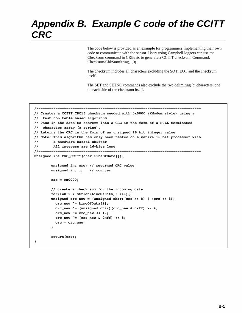
The code below is provided as an example for programmers implementing their own code to communicate with the sensor. Users using Campbell loggers can use the Checksum command in CRBasic to generate a CCITT checksum. Command: Checksum/ChkSumString,1,0).
The checksum includes all characters excluding the SOT, EOT and the checksum itself.
The SET and SETNC commands also exclude the two delimiting `:’ characters, one on each side of the checksum itself.
//----------------------------------------------------------------------------// Creates a CCITT CRC16 checksum seeded with 0x0000 (XModem style) using a// fast non table based algorithm.// Pass in the data to convert into a CRC in the form of a NULL terminated// character array (a string).// Returns the CRC in the form of an unsigned 16 bit integer value// Note: This algorithm has only been tested on a native 16-bit processor with// a hardware barrel shifter// All integers are 16-bits long//----------------------------------------------------------------------------unsigned int CRC_CCITT(char LineOfData[]){
unsigned int crc; // returned CRC valueunsigned int i; // counter
crc = 0x0000;
// create a check sum for the incoming datafor(i=0;i < strlen(LineOfData); i++){unsigned crc_new = (unsigned char)(crc >> 8) | (crc << 8);
crc_new ^= LineOfData[i];crc_new ^= (unsigned char)(crc_new & 0xff) >> 4;crc_new ^= crc_new << 12;crc_new ^= (crc_new & 0xff) << 5;crc = crc_new;
}
return(crc);}
B-1

CS125 Present Weather Sensor
B-2

C-1
Appendix C. Example CRBasic programs
C.1 CRBasic read program 'CR800 'Demonstration program to read data from a CS125 set to continuous output 'with the full SYNOP (default) message being transmitted 'Note: The CS125 emits this message every minute by default. Public Visibility 'These variables could be defined as DIM in a final program Public InString As String * 100 'Incoming string Public SerialIndest(27) As String, NBytesReturned Public ChecksumOK As Boolean Public lngCRCCalc As Long, lngCRCMsg As Long 'Define the aliases for the full message Alias SerialIndest(1)=Message_ID '0..2 Alias SerialIndest(2)=Sensor_ID '0..9 Alias SerialIndest(3)=System_status '0..3 Alias SerialIndest(4)=Interval_time '1..3600 Alias SerialIndest(5)=Visibilitystr '0..32000 metres Alias SerialIndest(6)= VisibilityUnits 'M or F for Metres or Feet Alias SerialIndest(7)=Averaging_duration '1 or 10 minutes Alias SerialIndest(8)=User_alarm_1 '0..1 - Visibility compared to Threshold One Alias SerialIndest(9)=User_alarm_2 '0..1 - Visibility compared to Threshold Two Alias SerialIndest(10)=Emitter_failure '0..2 - Emitter Failure Alias SerialIndest(11)=Emitter_lens_dirty '0..3 - Emitter Lens Dirty Alias SerialIndest(12)=Emitter_temp_error '0..3 - Emitter Temperature Alias SerialIndest(13)=Detector_lens_dirty '0..3 - Detector Lens Dirty Alias SerialIndest(14)=Detector_temp_error '0..3 - Detector Temperature Alias SerialIndest(15)=Detector_saturated '0..1 - Detector DC Saturation Level Alias SerialIndest(16)=Hood_temp_error '0..3 - Hood Temperature Alias SerialIndest(17)=External_temp_error '0..3 - External Temperature Alias SerialIndest(18)=Signature_error '0..1 - Signature Error Alias SerialIndest(19)=Flash_read_error '0..1 - Flash Read Error Alias SerialIndest(20)=Flash_write_error '0..1 - Flash Write Error Alias SerialIndest(21)=Particle_Limit_error '0 or 1 - Particle limit reached Alias SerialIndest(22)=Particle_Count Alias SerialIndest(23)=Intensity 'mm/h Alias SerialIndest(24)=SYNOP_code Alias SerialIndest(25)=Temperature 'deg C Alias SerialIndest(26)=Relative_Humidity '%, 0..100 Alias SerialIndest(27) = checksumrx 'CCITT Checksum 'Define the serial port to which the CS125 is connected - amend as needed Const CS125_Comport = COM1 'Main Program BeginProg 'Open the logger serial port to which the CS125 is connected SerialOpen (CS125_Comport,38400,3,0,1000) Scan(10,Sec,1,0) 'Sensor emits a message every 60 seconds by default so this will fail 5 'times out of 6 with a 10 second scan

CS125 Present Weather Sensor
C-2
SerialInRecord(CS125_Comport,InString,&h02,0,&h03,NBytesReturned,01) 'Check that a message has been recieved first If NBytesReturned > 0 Then 'Split out the Data into strings SplitStr (SerialIndest(),InString," ",27,5) 'Check the received checksum is valid 'Calculate the expected checksum lngCRCCalc = CheckSum(InString,1,NBytesReturned-5) 'Extract the checksum from the message & convert it for comparison lngCRCMsg = HexToDec(checksumrx) ChecksumOK = ( lngCRCMsg = lngCRCCalc) 'In critical applications the visibility can be set to NaN if the system status 'is degraded or a critical error flag is set. If ChecksumOK Then Visibility = Visibilitystr Else Visibility =NaN EndIf 'Call data storage commands here NextScan EndProg

Appendix C. Example CRBasic programs
C-3
C.2 CRBasic POLL program 'CR800 'Demonstration program to read data from a CS125 set to polled output 'with the full SYNOP (default) message being transmitted 'Note: the sensor needs to be configured to behave like this, it is not setup by this program. Public Visibility 'These variables could be defined as DIM in a final program Public InString As String * 100 'Incoming string Public SerialIndest(27) As String, NBytesReturned Public ChecksumOK As Boolean Public lngCRCCalc As Long, lngCRCMsg As Long 'Define the aliases for the full message Alias SerialIndest(1)=Message_ID '0..2 Alias SerialIndest(2)=Sensor_ID '0..9 Alias SerialIndest(3)=System_status '0..3 Alias SerialIndest(4)=Interval_time '1..3600 Alias SerialIndest(5)=Visibilitystr '0..32000 metres Alias SerialIndest(6)= VisibilityUnits 'M or F for Metres or Feet Alias SerialIndest(7)=Averaging_duration '1 or 10 minutes Alias SerialIndest(8)=User_alarm_1 '0..1 - Visibility compared to Threshold One Alias SerialIndest(9)=User_alarm_2 '0..1 - Visibility compared to Threshold Two Alias SerialIndest(10)=Emitter_failure '0..2 - Emitter Failure Alias SerialIndest(11)=Emitter_lens_dirty '0..3 - Emitter Lens Dirty Alias SerialIndest(12)=Emitter_temp_error '0..3 - Emitter Temperature Alias SerialIndest(13)=Detector_lens_dirty '0..3 - Detector Lens Dirty Alias SerialIndest(14)=Detector_temp_error '0..3 - Detector Temperature Alias SerialIndest(15)=Detector_saturated '0..1 - Detector DC Saturation Level Alias SerialIndest(16)=Hood_temp_error '0..3 - Hood Temperature Alias SerialIndest(17)=External_temp_error '0..3 - External Temperature Alias SerialIndest(18)=Signature_error '0..1 - Signature Error Alias SerialIndest(19)=Flash_read_error '0..1 - Flash Read Error Alias SerialIndest(20)=Flash_write_error '0..1 - Flash Write Error Alias SerialIndest(21)=Particle_Limit_error '0 or 1 - Particle limit reached Alias SerialIndest(22)=Particle_Count Alias SerialIndest(23)=Intensity 'mm/h Alias SerialIndest(24)=SYNOP_code Alias SerialIndest(25)=Temperature 'deg C Alias SerialIndest(26)=Relative_Humidity '%, 0..100 Alias SerialIndest(27) = checksumrx 'CCITT Checksum 'Define the serial port to which the CS125 is connected - amend as needed Const CS125_Comport = COM1 'Preload the poll command for a sensor for address 0, in this example 'If the sensor has a different address uncomment the relevant line Const CS125_Poll = CHR(2)&"POLL:0:0:3A3B:"&CHR(3)&CHR(13) 'address 0 'Const CS125_Poll = CHR(2)&"POLL:1:0:0D0B:"&CHR(3)&CHR(13) 'address 1 'Const CS125_Poll = CHR(2)&"POLL:2:0:545B:"&CHR(3)&CHR(13) 'address 2 'Const CS125_Poll = CHR(2)&"POLL:3:0:636B:"&CHR(3)&CHR(13) 'address 3 'Const CS125_Poll = CHR(2)&"POLL:4:0:E6FB:"&CHR(3)&CHR(13) 'address 4 'Const CS125_Poll = CHR(2)&"POLL:5:0:D1CB:"&CHR(3)&CHR(13) 'address 5 'Const CS125_Poll = CHR(2)&"POLL:6:0:889B:"&CHR(3)&CHR(13) 'address 6 'Const CS125_Poll = CHR(2)&"POLL:7:0:BFAB:"&CHR(3)&CHR(13) 'address 7

CS125 Present Weather Sensor
C-4
'Const CS125_Poll = CHR(2)&"POLL:8:0:939A:"&CHR(3)&CHR(13) 'address 8 'Const CS125_Poll = CHR(2)&"POLL:9:0:A4AA:"&CHR(3)&CHR(13) 'address 9 'Main Program BeginProg 'Open the logger serial port to which the CS125 is connected SerialOpen (CS125_Comport,38400,3,0,1000) Scan(10,Sec,1,0) 'The sensor is polled every 10 seconds SerialOut(CS125_Comport,CS125_Poll,"",0,100) SerialInRecord(CS125_Comport,InString,&h02,0,&h03,NBytesReturned,01) 'Check that a message has been recieved first If NBytesReturned > 0 Then SplitStr (SerialIndest(),InString," ",27,5) 'Check the received checksum is valid 'Calculate the expected checksum lngCRCCalc = CheckSum(InString,1,NBytesReturned-5) 'Extract the checksum from the message & convert it for comparison lngCRCMsg = HexToDec(checksumrx) ChecksumOK = ( lngCRCMsg = lngCRCCalc) 'In critical applications the visibility can be set to NaN if the system status 'is degraded or a critical error flag is set. If ChecksumOK Then Visibility = Visibilitystr Else Visibility =NaN EndIf 'Call data storage commands here NextScan EndProg
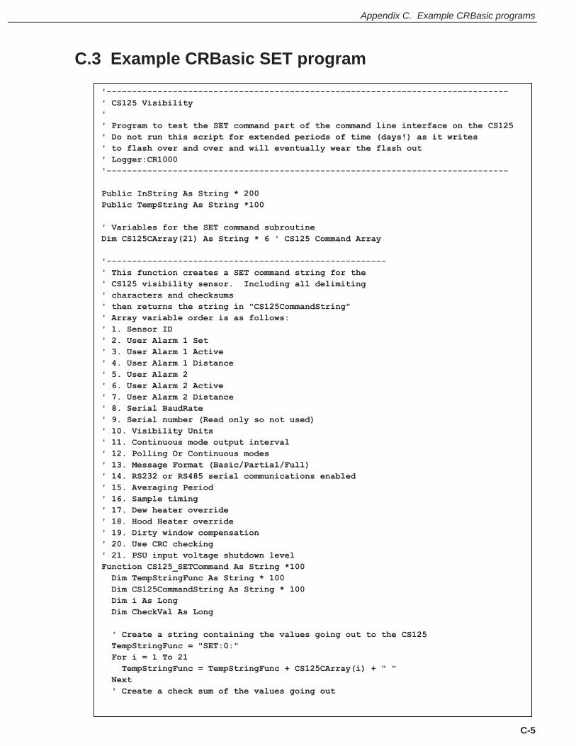
Appendix C. Example CRBasic programs
C-5
C.3 Example CRBasic SET program '------------------------------------------------------------------------------- ' CS125 Visibility ' ' Program to test the SET command part of the command line interface on the CS125 ' Do not run this script for extended periods of time (days!) as it writes ' to flash over and over and will eventually wear the flash out ' Logger:CR1000 '------------------------------------------------------------------------------- Public InString As String * 200 Public TempString As String *100 ' Variables for the SET command subroutine Dim CS125CArray(21) As String * 6 ' CS125 Command Array '------------------------------------------------------- ' This function creates a SET command string for the ' CS125 visibility sensor. Including all delimiting ' characters and checksums ' then returns the string in "CS125CommandString" ' Array variable order is as follows: ' 1. Sensor ID ' 2. User Alarm 1 Set ' 3. User Alarm 1 Active ' 4. User Alarm 1 Distance ' 5. User Alarm 2 ' 6. User Alarm 2 Active ' 7. User Alarm 2 Distance ' 8. Serial BaudRate ' 9. Serial number (Read only so not used) ' 10. Visibility Units ' 11. Continuous mode output interval ' 12. Polling Or Continuous modes ' 13. Message Format (Basic/Partial/Full) ' 14. RS232 or RS485 serial communications enabled ' 15. Averaging Period ' 16. Sample timing ' 17. Dew heater override ' 18. Hood Heater override ' 19. Dirty window compensation ' 20. Use CRC checking ' 21. PSU input voltage shutdown level Function CS125_SETCommand As String *100 Dim TempStringFunc As String * 100 Dim CS125CommandString As String * 100 Dim i As Long Dim CheckVal As Long ' Create a string containing the values going out to the CS125 TempStringFunc = "SET:0:" For i = 1 To 21 TempStringFunc = TempStringFunc + CS125CArray(i) + " " Next ' Create a check sum of the values going out

CS125 Present Weather Sensor
C-6
CheckVal = CheckSum (TempStringFunc,1,0) ' Use the CCITT CRC16 checksum ' Create final string going out to CS125 including start characters and end characters CS125CommandString = CHR(2) + TempStringFunc + ":" + FormatLong (CheckVal,"%04X") + ":" + CHR(3) + CHR(13) + CHR(10) 'CS125CommandString = CHR(2) + TempStringFunc + CHR(3) + CHR(13) + CHR(10) ' Use this line if no checksum is desired Return(CS125CommandString) EndFunction '------------------------------------------------------- 'Main Program BeginProg ' open port to the visibility sensor using Com1 SerialOpen (Com1,38400,3,0,10000) ' Note: Change the following array variable to suit your own application ' load example/dummy values into the array CS125CArray(1) = 0 ' Set ID to 0 CS125CArray(2) = 1 ' Enable alarm 1 CS125CArray(3) = 1 ' Set alarm 1 to if greater than CS125CArray(4) = 1000 ' Set alarm 1 trigger distance to 1000 CS125CArray(5) = 1 ' Enable alarm 2 CS125CArray(6) = 0 ' Set alarm 2 to if less than CS125CArray(7) = 15000 ' Set alarm 2 trigger distance to 15000 CS125CArray(8) = 2 ' Set serial baud rate to 38400bps CS125CArray(9) = 0 ' Read only so dummy value added here, but not needed CS125CArray(10) = "M" ' Set unit type to metres (use upper case) CS125CArray(11) = 60 ' Set output period to 60 seconds CS125CArray(12) = 1 ' Polling mode CS125CArray(13) = 2 ' Set FULL output message format CS125CArray(14) = 0 ' Set RS232 serial mode CS125CArray(15) = 1 ' Set averaging over one minute CS125CArray(16) = 1 ' Set sample timing to one second CS125CArray(17) = 0 ' Set dew heaters to automatic CS125CArray(18) = 0 ' Set hood heaters to automatic CS125CArray(19) = 0 ' Don't use dirty window compensation CS125CArray(20) = 1 ' Use CRC checking on incoming command line data CS125CArray(21) = 7.0 ' Set Low voltage battery shutdown to a very low value so it doesn't trigger ' Send information once every 10 seconds Scan (10,Sec,0,0) TempString = CS125_SETCommand() ' Create the outgoing string SerialOut (Com1,TempString,"",0,100) ' Send SET command to the CS125 Delay (1,1,Sec) SerialIn (InString,Com1,100,0,1000) ' Grab retuned data from the CS125 ' Returned data is identical to the ' data a GET command would return NextScan EndProg
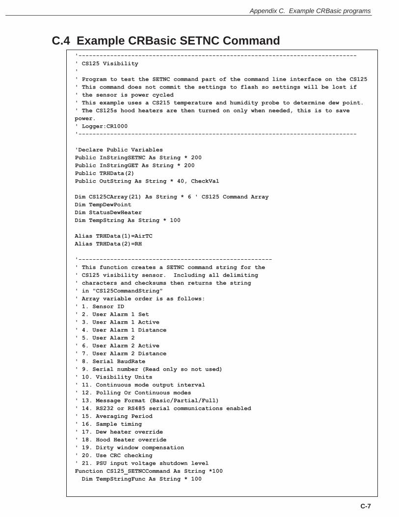
Appendix C. Example CRBasic programs
C-7
C.4 Example CRBasic SETNC Command '------------------------------------------------------------------------------- ' CS125 Visibility ' ' Program to test the SETNC command part of the command line interface on the CS125 ' This command does not commit the settings to flash so settings will be lost if ' the sensor is power cycled ' This example uses a CS215 temperature and humidity probe to determine dew point. ' The CS125s hood heaters are then turned on only when needed, this is to save power. ' Logger:CR1000 '------------------------------------------------------------------------------- 'Declare Public Variables Public InStringSETNC As String * 200 Public InStringGET As String * 200 Public TRHData(2) Public OutString As String * 40, CheckVal Dim CS125CArray(21) As String * 6 ' CS125 Command Array Dim TempDewPoint Dim StatusDewHeater Dim TempString As String * 100 Alias TRHData(1)=AirTC Alias TRHData(2)=RH '------------------------------------------------------- ' This function creates a SETNC command string for the ' CS125 visibility sensor. Including all delimiting ' characters and checksums then returns the string ' in "CS125CommandString" ' Array variable order is as follows: ' 1. Sensor ID ' 2. User Alarm 1 Set ' 3. User Alarm 1 Active ' 4. User Alarm 1 Distance ' 5. User Alarm 2 ' 6. User Alarm 2 Active ' 7. User Alarm 2 Distance ' 8. Serial BaudRate ' 9. Serial number (Read only so not used) ' 10. Visibility Units ' 11. Continuous mode output interval ' 12. Polling Or Continuous modes ' 13. Message Format (Basic/Partial/Full) ' 14. RS232 or RS485 serial communications enabled ' 15. Averaging Period ' 16. Sample timing ' 17. Dew heater override ' 18. Hood Heater override ' 19. Dirty window compensation ' 20. Use CRC checking ' 21. PSU input voltage shutdown level Function CS125_SETNCCommand As String *100 Dim TempStringFunc As String * 100

CS125 Present Weather Sensor
C-8
Dim CS125CommandString As String * 100 Dim i As Long
Dim CheckVal As Long ' Create a string containing the values going out to the CS125 TempStringFunc = "SETNC:0:" For i = 1 To 21 TempStringFunc = TempStringFunc + CS125CArray(i) + " " Next ' Create a check sum of the values going out CheckVal = CheckSum (TempStringFunc,1,0) ' Use the CCITT CRC16 checksum ' Create final string going out to CS125 including start characters and end characters CS125CommandString = CHR(2) + TempStringFunc + ":" + FormatLong (CheckVal,"%04X") + ":" + CHR(3) + CHR(13) + CHR(10) 'CS125CommandString = CHR(2) + TempStringFunc + CHR(3) + CHR(13) + CHR(10) ' Use this line if no checksum is desired Return(CS125CommandString) EndFunction '------------------------------------------------------- 'Main Program BeginProg ' Open port to the visibility sensor using Com1 SerialOpen (Com1,115200,3,0,10000) ' Note: Change the following array variable to suit your own application ' load example/dummy values into the array ' Loading the array is not strictly necessary, but is done as a fail safe in ' case the GET command does not return data CS125CArray(1) = 0 ' Set ID to 0 CS125CArray(2) = 0 ' Disable alarm 1 CS125CArray(3) = 1 ' Set alarm 1 to if greater than CS125CArray(4) = 10000 ' Set alarm 1 trigger distance to 10000 CS125CArray(5) = 0 ' Disable alarm 2 CS125CArray(6) = 0 ' Set alarm 2 to if less than CS125CArray(7) = 10000 ' Set alarm 2 trigger distance to 10000 CS125CArray(8) = 0 ' Set serial baud rate to 115200bps CS125CArray(9) = 0 ' Read only so dummy value added here, but not needed CS125CArray(10) = "M" ' Set unit type to metres (use upper case)
CS125CArray(11) = 60 ' Set output period to 60 seconds CS125CArray(12) = 1 ' Polling mode CS125CArray(13) = 2 ' Set FULL output message format CS125CArray(14) = 0 ' Set RS232 serial mode CS125CArray(15) = 1 ' Set averaging over one minute CS125CArray(16) = 1 ' Set sample timing to one second CS125CArray(17) = 0 ' Set dew heaters to automatic CS125CArray(18) = 0 ' Set hood heaters to automatic CS125CArray(19) = 0 ' Don't use dirty window compensation CS125CArray(20) = 1 ' Use CRC checking on incoming command line data CS125CArray(21) = 7.0 ' Set Low voltage battery shutdown to a very low value so it doesn't trigger
StatusDewHeater=False Scan (10,Sec,0,0)

Appendix C. Example CRBasic programs
C-9
'CS215 Temperature & Relative Humidity Sensor measurements AirTC and RH SDI12Recorder(TRHData(),5,"0","M!",1,0) 'Calculate DewPoint DewPoint(TempDewPoint,AirTC,RH) ' Gather the current settings from the CS125 SerialFlush (Com1) TempString = "GET:0:0" CheckVal = CheckSum (TempString,1,0) ' Use the CCITT CRC16 checksum OutString = CHR(2) + TempString + ":" + FormatLong (CheckVal,"%04X") + ":" + CHR(3) + CHR(13) + CHR(10) SerialOut (Com1,OutString,"",0,100) ' Send GET command to the CS125 Delay (1,1,Sec) SerialIn (InStringGET,Com1,100,0,200) ' Save the data returned from the GET command If Len(InStringGET) > 1 Then ' Check data was returned SplitStr (CS125CArray(1),InStringGET, " ",21,5) ' Strip the settings from the returned data string CS125CArray(1) = Right (CS125CArray(1),1)' Trim the SOT from the first data point EndIf 'Enable Dew Heaters if AirTC < DewPoint If AirTC <= TempDewPoint AND StatusDewHeater=False Then CS125CArray(17)=0 SerialFlush (Com1) TempString = CS125_SETNCCommand() SerialOut (Com1,TempString,"",0,100) Delay (1,1,Sec) SerialIn (InStringSETNC,Com1,100,0,1000) StatusDewHeater=True EndIf 'Disable Dew Heaters if AirTC > DewPoint+3 If AirTC > TempDewPoint+3 AND StatusDewHeater=True Then CS125CArray(17)=1 SerialFlush (Com1) TempString = CS125_SETNCCommand() SerialOut (Com1,TempString,"",0,100) Delay (1,1,Sec) SerialIn (InStringSETNC,Com1,100,0,1000) StatusDewHeater=False EndIf NextScan EndProg

CS125 Present Weather Sensor
C-10
C.5 Example CRBasic GET program
'------------------------------------------------------------------------------- ' CS125 Visibility ' ' Program to test the GET command part of the command line interface on the CS125 ' Connecting to serial port one on a CR1000 logger ' Logger:CR1000 ' ' Example outputs including checksums (varies with sensor ID) ' GET:0:0:2C67: ' GET:1:0:1B57: ' GET:2:0:4207: ' GET:3:0:7537: ' GET:4:0:F0A7: ' GET:5:0:C797: ' GET:6:0:9EC7: ' GET:7:0:A9F7: ' GET:8:0:85C6: ' GET:9:0:B2F6: '------------------------------------------------------------------------------- Public OutString As String * 40 ' Outgoing string Dim CheckVal As Long ' Checksum value Public InString As String * 200 ' Incomming string Dim TempString As String * 16 'Main Program BeginProg SerialOpen (Com1,38400,3,0,10000) ' open port to the visibility sensor ' Send a request for information once every 10 seconds Scan (10,Sec,0,0) ' Create the basic GET string for the CS125 TempString = "GET:0:0" CheckVal = CheckSum (TempString,1,0) ' Use the CCITT CRC16 checksum OutString = CHR(2) + TempString + ":" + FormatLong (CheckVal,"%04X") + ":" + CHR(3) + CHR(13) + CHR(10)
SerialOut (Com1,OutString,"",0,100) ' Send GET command to the CS125
Delay (1,1,Sec)
SerialIn (InString,Com1,100,0,200) ' Save the data returned from the GET command
NextScan EndProg

Appendix C. Example CRBasic programs
C-11

CAMPBELL SCIENTIFIC COMPANIES
Campbell Scientific, Inc. (CSI) 815 West 1800 North Logan, Utah 84321 UNITED STATES
www.campbellsci.com [email protected]
Campbell Scientific Africa Pty. Ltd. (CSAf) PO Box 2450
Somerset West 7129 SOUTH AFRICA
www.csafrica.co.za [email protected]
Campbell Scientific Australia Pty. Ltd. (CSA) PO Box 8108
Garbutt Post Shop QLD 4814 AUSTRALIA
www.campbellsci.com.au [email protected]
Campbell Scientific do Brazil Ltda. (CSB) Rua Apinagés, nbr. 2018 - Perdizes
CEP: 01258-00 São Paulo SP BRAZIL www.campbellsci.com.br [email protected]
Campbell Scientific Canada Corp. (CSC)
14532 – 131 Avenue NW Edmonton, Alberta T5L 4X4
CANADA www.campbellsci.ca [email protected]
Campbell Scientific Centro Caribe S.A. (CSCC)
300N Cementerio, Edificio Breller Santo Domingo, Heredia 40305
COSTA RICA www.campbellsci.cc [email protected]
Campbell Scientific Ltd. (CSL)
Campbell Park 80 Hathern Road, Shepshed, Loughborough LE12 9GX
UNITED KINGDOM www.campbellsci.co.uk [email protected]
Campbell Scientific Ltd. (France)
3 Avenue de la Division Leclerc 92160 ANTONY
FRANCE www.campbellsci.fr [email protected]
Campbell Scientific Spain, S. L.
Avda. Pompeu Fabra 7-9 Local 1 - 08024 BARCELONA
SPAIN www.campbellsci.es [email protected]
Campbell Scientific Ltd. (Germany) Fahrenheitstrasse13, D-28359 Bremen
GERMANY www.campbellsci.de [email protected]
Campbell Scientific (Beijing) Co., Ltd. 8B16, Floor 8 Tower B, Hanwei Plaza
7 Guanghua Road, Chaoyang, Beijing 100004 P.R. CHINA
www.campbellsci.com [email protected]
Please visit www.campbellsci.com to obtain contact information for your local US or International representative.