Embed Size (px)
Citation preview

1 26/10/2005 Version 1.0 1SBC146010C1701
1SBC146010C1701 Technical Presentation CS range 1.0 - Version 1.0
Technical argumentation CS Range
Argumentation technique Gamme CS
Hall effect closed-loop current sensors Capteurs de courant à effet Hall boucle-fermée

2 26/10/2005 Version 1.0 1SBC146010C1701

3 26/10/2005 Version 1.0 1SBC146010C1701
SUMMARY 1 The customers' technical needs 4 2 The aimed applications 5 3 The technology 5 4 The range 7 5 The main characteristics 10 6 The options and accessories 10 7 The electrical connections 12 8 The advantages 13 9 The used standards 14 10 The technical documentation 17
SOMMAIRE 1 Les besoins techniques clients 4 2 Les applications visées 5 3 La technologie 5 4 La gamme 7 5 Les principales caractéristiques 10 6 Les options et accessoires 10 7 Les connexions électriques 12 8 Les avantages 13 9 Les normes appliquées 14 10 La documentation technique 17
This document cannot be duplicated in any manner, without prior authorization from ABB Entrelec
Ce document ne peut-être dupliqué sous quelque forme que ce soit, sans autorisation préalable de ABB Entrelec
© A
BB
Ent
rele
c -1
-C
S P
rese
ntat
ion
1.0
Sep
-200
5
Current and voltage sensors CS range Technical Presentation

4 26/10/2005 Version 1.0 1SBC146010C1701
© A
BB
Ent
rele
c -
2 -C
S P
rese
ntat
ion
1.0
Sep
-200
5Technical presentation summary
1 The customer’s needs
2 The aimed applications
3 The technology
4 The range
5 The main characteristics
6 The options and accessories
7 The electrical connections
8 The advantages
9 The used standards
10 The technical documentation
© A
BB
Ent
rele
c -
3 -C
S P
rese
ntat
ion
1.0
Sep
-200
5
1 The customers’ needs
Price
High quality
High performances
Reliability
Compactness
Latest standards
Reliable supplier
20982098
IECIECENEN
$$
100% OK
5 26/10/2005 Version 1.0 1SBC146010C1701
© A
BB
Ent
rele
c -
4 -C
S P
rese
ntat
ion
1.0
Sep
-200
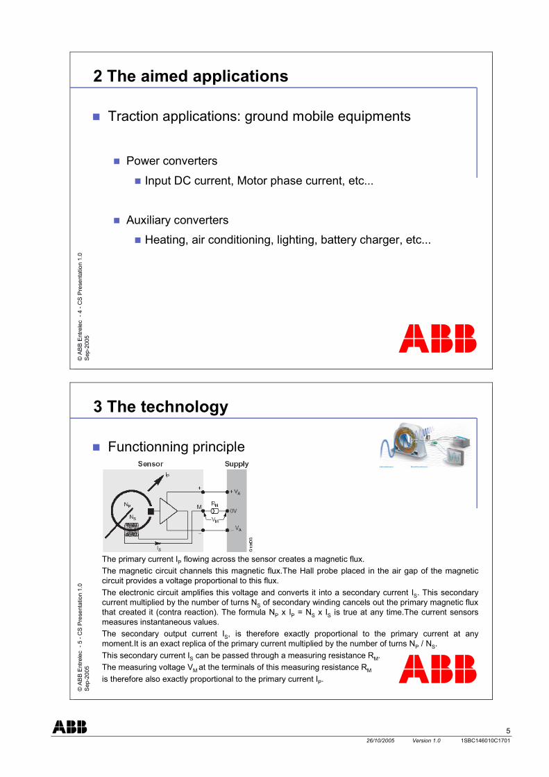
52 The aimed applications
Traction applications: ground mobile equipments
Power converters
Input DC current, Motor phase current, etc...
Auxiliary converters
Heating, air conditioning, lighting, battery charger, etc...
© A
BB
Ent
rele
c -
5 -C
S P
rese
ntat
ion
1.0
Sep
-200
5
3 The technology
Functionning principle
The primary current IP flowing across the sensor creates a magnetic flux.The magnetic circuit channels this magnetic flux.The Hall probe placed in the air gap of the magnetic circuit provides a voltage proportional to this flux.The electronic circuit amplifies this voltage and converts it into a secondary current IS. This secondary current multiplied by the number of turns NS of secondary winding cancels out the primary magnetic flux that created it (contra reaction). The formula NP x IP = NS x IS is true at any time.The current sensors measures instantaneous values.The secondary output current IS, is therefore exactly proportional to the primary current at any moment.It is an exact replica of the primary current multiplied by the number of turns NP / NS. This secondary current IS can be passed through a measuring resistance RM.The measuring voltage VM at the terminals of this measuring resistance RM
is therefore also exactly proportional to the primary current IP.

6 26/10/2005 Version 1.0 1SBC146010C1701
© A
BB
Ent
rele
c -
6 -C
S P
rese
ntat
ion
1.0
Sep
-200
53 The technology
Technologies comparison for current sensing
Shunt Current Transformer Open Loop Closed
LoopInsulation P/S NO YES YES YESBandw idth DC to few
kHzAC only DC to few
kHzDC to 100
kHzMeasuring range Low Medium Medium HighMaximum overloads Very Low Low Low High
Power dissipation High Medium Very Low LowOutput signal Voltage Current Voltage CurrentSupply voltage No need No need ± V ± VAccuracy 0.5 to 2% 0.5 to 2% 2 to 4% < 1%Price Low Medium Medium High
© A
BB
Ent
rele
c -
7 -C
S P
rese
ntat
ion
1.0
Sep
-200
5
3 The technology
Major advantages of the CS technology (closed loop Hall effect technology)
Galvanic isolation
High accuracy
Fast response time
Excellent linearity
Wide continuous measuring range
Low power dissipation (no heating)

7 26/10/2005 Version 1.0 1SBC146010C1701
© A
BB
Ent
rele
c -
8 -C
S P
rese
ntat
ion
1.0
Sep
-200
54 The range
General range presentation:300 A r.m.s. up to 2000A r.m.s.
300A r.m.s. => CS300
500A r.m.s. => CS500 / CS503
1000A r.m.s. => CS1000
2000A r.m.s. => CS2000
© A
BB
Ent
rele
c -
9 -C
S P
rese
ntat
ion
1.0
Sep
-200
5
4 The range
CS range: Technology: closed loop Hall effect
Measuring range: up to ±2 x IPN (few minutes/hour)
Temperature: -40°C to +85°C
Supply voltage: ±15V…±24V
Bandwidth: 0 to >100kHz
Global accuracy: <±1% (-40°C to +85°C)
Dielectric strength: EN50124-1 (from 6.5kV up to 12kV)
Options: turns ratio, secondary terminals, fixing mode, screen, primary bar

8 26/10/2005 Version 1.0 1SBC146010C1701
© A
BB
Ent
rele
c -
10 -
CS
Pre
sent
atio
n 1.
0S
ep-2
005
4 The range
CS range mechanical layout
CS300 / CS503Size 0
CS500 / CS1000Size 1
Horizontal mounting
© A
BB
Ent
rele
c -
11 -
CS
Pre
sent
atio
n 1.
0S
ep-2
005
4 The range
CS range mechanical layout
CS2000Size 2
Horizontal mounting

9 26/10/2005 Version 1.0 1SBC146010C1701
© A
BB
Ent
rele
c -
12 -
CS
Pre
sent
atio
n 1.
0S
ep-2
005
4 The range
CS range mechanical layoutVertical mounting
CS300 / CS503Size 0
CS500 / CS1000Size 1
© A
BB
Ent
rele
c -
13 -
CS
Pre
sent
atio
n 1.
0S
ep-2
005
4 The range
CS range mechanical layout
CS2000Size 2
Vertical mounting

10 26/10/2005 Version 1.0 1SBC146010C1701
© A
BB
Ent
rele
c -
14 -
CS
Pre
sent
atio
n 1.
0S
ep-2
005
5 The main characteristics
CS range main standard characteristicsCS300 CS503 CS500 CS1000 CS2000
Nominal primary current IPN A r.m.s. 300 500 500 1000 2000Measuring range IPMAX @ ±24V±5% A peak ±600 ±750 ±1000 ±2000 ±3000Turn number NS 2000 3500 5000 (1) 5000 (1) 5000 (1)Secondary current at IPN IS mA 150 142.86 100 (1) 200 (1) 400 (1)Accuracy at IPN Err% @ +25°C %Linearity Lin %Delay time dt µsdi/dt correctly followed di/dt A/µsBandwidth BW -1dB kHzMax. no-load consumption current lao @ ±24V±5% mA <10 <15 <15 <15 <25Dielectric strength Primary/Secondary Ud_p/s 50 Hz, 1 min kV 6.5 6.5 12 12 12Supply voltage VA ±5% V d.c.Operating temperature T°op °CStorage temperature T°st °C(1) Other standard values available
<±0.5<0.1<1
<100<100
±15 … ±24-40 …+85-50 … +90
© A
BB
Ent
rele
c -
15 -
CS
Pre
sent
atio
n 1.
0S
ep-2
005
6 The options and accessories
CS range : electrical optionsSpecial turns ratio: for 300A to 500A rated sensors
Temperature range : -40...85°C
CS range : terminals optionsStandard output connections:
3 x M5 studs3 x 6.35 x 0.8 Faston
4 x M5 studs4 x 6.35 x 0.8 Faston
4 x M5 studs

11 26/10/2005 Version 1.0 1SBC146010C1701
© A
BB
Ent
rele
c -
16 -
CS
Pre
sent
atio
n 1.
0S
ep-2
005
6 The options and accessories
Optional output connections:
Shielded cable
3 or 4 inserts
Others on request...
LEMO Connector:
© A
BB
Ent
rele
c -
17 -
CS
Pre
sent
atio
n 1.
0S
ep-2
005
6 The options and accessories
Accessories:Primary bars:
For CS300 and CS503Bar CST0: 155 x 25 x 6
For CS500Bar CST1-6: 185 x 40 x 6Bar CST1-10: 185 x 40 x 10Bar CST1 special: 210 x 40 x 10
For CS1000Bar CST1-6: 185 x 40 x 6Bar CST1-10: 185 x 40 x 10
For CS2000Bar CST2: 240 x 60 x 20Bar CST2 special: 370 x 60 x 20

12 26/10/2005 Version 1.0 1SBC146010C1701
© A
BB
Ent
rele
c -
18 -
CS
Pre
sent
atio
n 1.
0S
ep-2
005
6 The options and accessories
Accessories:Side Plates for vertical mounting and / or for primary bar:
For CS300 and CS503 (size 0 – kit CST0)
For CS500 and CS1000 (size 1 – kt CST1)
For CS2000 (size 2 – kit CST2)
© A
BB
Ent
rele
c -
19 -
CS
Pre
sent
atio
n 1.
0S
ep-2
005
7 The electrical connections
CS range: connection diagramBi-directionnal power supply Power
supply
+VA
-VA
0VIS
+
M
- RM

13 26/10/2005 Version 1.0 1SBC146010C1701
© A
BB
Ent
rele
c -
20 -
CS
Pre
sent
atio
n 1.
0S
ep-2
005
7 The electrical connections
Uni-directionnal power supply
Powersupply
+VA
0VRM
0…-VA
Signaldiode
+VA…0
Powersupply
-VA
0VSignaldiode
+M
-+
M
- RM
© A
BB
Ent
rele
c -
21 -
CS
Pre
sent
atio
n 1.
0S
ep-2
005
8 The advantages
ConstructionThe first and most compact product since 1997
High performanceHigh external magnetic fields rejection
High measuring capabilities
A traction current sensor 100% resin pottedElectronic board protected
Withstand high vibration constraints
High thermal capacities
The best compromise: performance/volume/price
Recyclable packaging

14 26/10/2005 Version 1.0 1SBC146010C1701
© A
BB
Ent
rele
c -
22 -
CS
Pre
sent
atio
n 1.
0S
ep-2
005
8 The advantages
Set-up flexibilityAccurate customer’s needs optimise sensor selection knowing:
Max. permanent operating temperature
Max. measurable current with duration
Max. over current (not measurable) with duration
Max. voltage on burden resistance at IPMAX
Min. supply voltage
Mechanical flexibility: Terminals, Side plates, turns ratio, primary bars, … due to modular sensor design
© A
BB
Ent
rele
c -
23 -
CS
Pre
sent
atio
n 1.
0S
ep-2
005
9 The used standards: railways applications
EN50155Testing (see details in the concerned Type Test Report)
Functioning : @ +25°C, @-40°C, @+85°C
: delay time
: di/dt
: bandwidth
: overload
: magnetic environment
: power supply over/under voltage
Other climatic tests : salt mist
: humid heat cycling
: storage
15 26/10/2005 Version 1.0 1SBC146010C1701
© A
BB
Ent
rele
c -
24 -
CS
Pre
sent
atio
n 1.
0S
ep-2
005
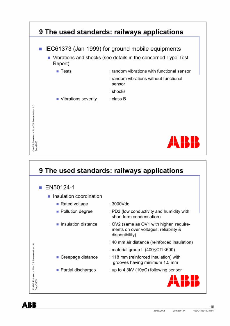
9 The used standards: railways applications
IEC61373 (Jan 1999) for ground mobile equipmentsVibrations and shocks (see details in the concerned Type Test Report)
Tests : random vibrations with functional sensor
: random vibrations without functional sensor
: shocks
Vibrations severity : class B
© A
BB
Ent
rele
c -
25 -
CS
Pre
sent
atio
n 1.
0S
ep-2
005
9 The used standards: railways applications
EN50124-1Insulation coordination
Rated voltage : 3000Vdc
Pollution degree : PD3 (low conductivity and humidity with short term condensation)
Insulation distance : OV2 (same as OV1 with higher require-ments on over voltages, reliability & disponibility)
: 40 mm air distance (reinforced insulation)
: material group II (400<CTI<600)
Creepage distance : 118 mm (reinforced insulation) with grooves having minimum 1.5 mm
Partial discharges : up to 4.3kV (10pC) following sensor
16 26/10/2005 Version 1.0 1SBC146010C1701
© A
BB
Ent
rele
c -
26 -
CS
Pre
sent
atio
n 1.
0S
ep-2
005
9 The used standards: railways applications
EN50121-3-2 for ground mobile equipmentsElectro-magnetic compatibility (see details in the concerned Type Test Report)
Emission : Conducted emission (tab 3)
: Radiated emission (tab 6)
© A
BB
Ent
rele
c -
27 -
CS
Pre
sent
atio
n 1.
0S
ep-2
005
9 The used standards: railways applications
EN50121-3-2 for ground mobile equipmentsElectro-magnetic compatibility (see details in the concerned Type Test Report)
Immunity : Electrical fast transients burst
: Surge
: Electrostatic discharge
: Conducted perturbations
: Radiated electromagnetic fields
: Network magnetic fields

17 26/10/2005 Version 1.0 1SBC146010C1701
© A
BB
Ent
rele
c -
28 -
CS
Pre
sent
atio
n 1.
0S
ep-2
005
10 The technical documentation
Technical fileTechnical presentation: this document
Functioning description
Mounting instructions
Technical data sheets
Type tests report synthesis
MTBF calculation
Fire/smoke certificate
Environmental certificate

18 26/10/2005 Version 1.0 1SBC146010C1701

19 26/10/2005 Version 1.0 1SBC146010C1701

20 26/10/2005 Version 1.0 1SBC146010C1701
ABB Entrelec Control Division 10, rue Ampère Z.I. - B.P. 114 F-69685 Chassieu cedex / France Telephone: +(33) (0) 4 7222 1722 Fax: +(33) (0) 4 7222 1969 http://www.abb.com/lowvoltage E-mail : [email protected]
Pub
licat
ion
N°
1SB
C14
6010
C17
01
Prin
ted
in F
ranc
e (Y
09.
2005
L)
As part of its on-going product improvement, ABB reverses the right to modify the characteristics of the products described in this document. The information given is not contractual. For further details please contact the Company marketing these products in your country.