Embed Size (px)
Citation preview
CS 640: Introduction to Computer Networks
Aditya Akella
Lecture 7 -IP: Addressing and Forwarding
2
From the previous lecture…• We will cover spanning tree from the
last lecture
3
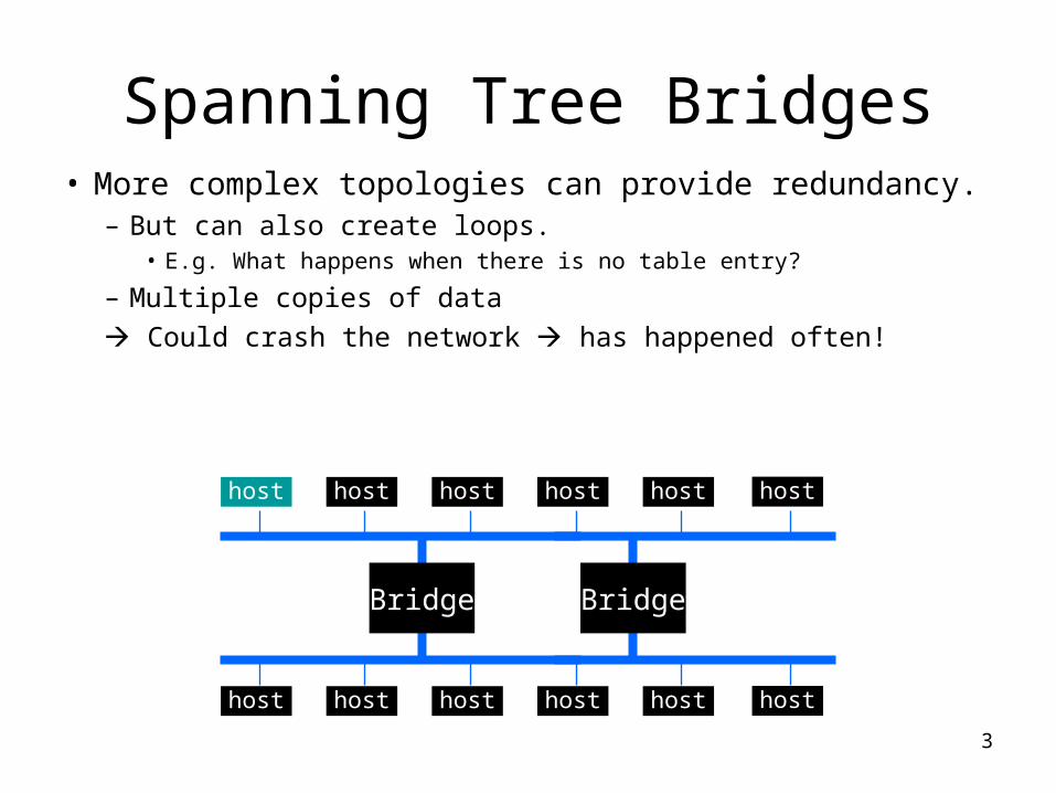
Spanning Tree Bridges• More complex topologies can provide redundancy.
– But can also create loops.• E.g. What happens when there is no table entry?
– Multiple copies of data Could crash the network has happened often!
host host host host host
host host host host host
host
host
Bridge Bridge
4
Spanning Tree Protocol Overview
Embed a tree that provides a single unique default path to each destination:
Bridges designate ports over which they will or will not forward frames
By removing ports, extended LAN is reduced to a tree
5
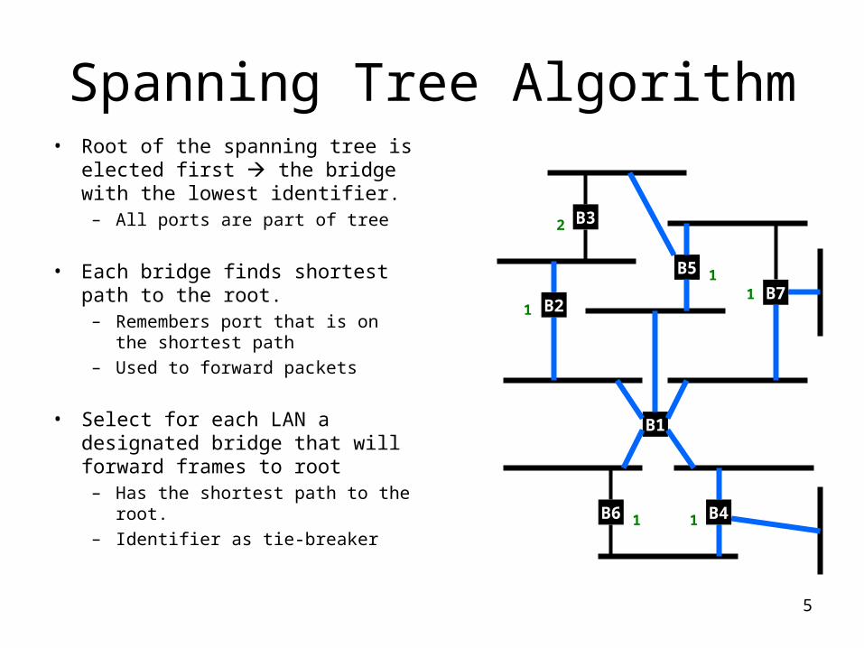
Spanning Tree Algorithm• Root of the spanning tree is
elected first the bridge with the lowest identifier.– All ports are part of tree
• Each bridge finds shortest path to the root.– Remembers port that is on the
shortest path– Used to forward packets
• Select for each LAN a designated bridge that will forward frames to root– Has the shortest path to the
root.– Identifier as tie-breaker
B3
B7
B5
B2
B1
B4B6
1
2
11
1 1
6
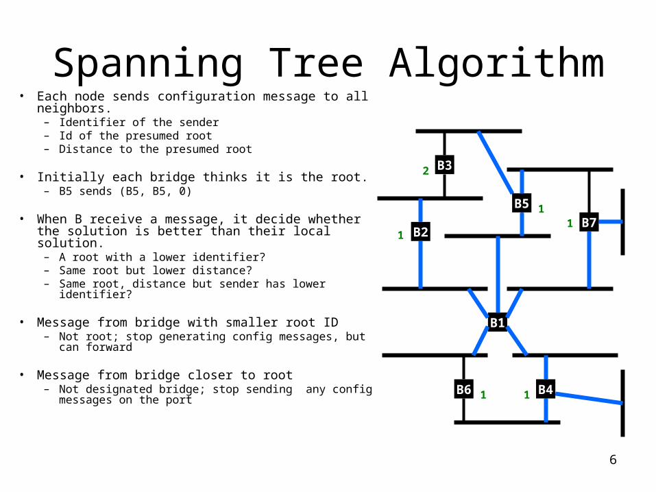
Spanning Tree Algorithm• Each node sends configuration message to all
neighbors.– Identifier of the sender– Id of the presumed root– Distance to the presumed root
• Initially each bridge thinks it is the root.– B5 sends (B5, B5, 0)
• When B receive a message, it decide whether the solution is better than their local solution.– A root with a lower identifier?– Same root but lower distance?– Same root, distance but sender has lower
identifier?
• Message from bridge with smaller root ID– Not root; stop generating config messages, but
can forward
• Message from bridge closer to root – Not designated bridge; stop sending any config
messages on the port
B3
B7
B5
B2
B1
B4B6
1
2
11
1 1
7
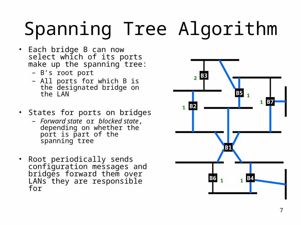
Spanning Tree Algorithm• Each bridge B can now select
which of its ports make up the spanning tree:– B’s root port– All ports for which B is the
designated bridge on the LAN
• States for ports on bridges– Forward state or blocked
state, depending on whether the port is part of the spanning tree
• Root periodically sends configuration messages and bridges forward them over LANs they are responsible for
B3
B7
B5
B2
B1
B4B6
1
2
11
1 1
8
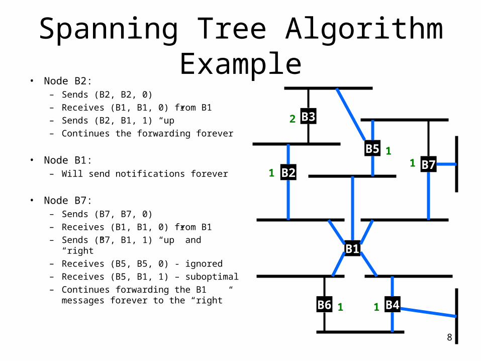
Spanning Tree AlgorithmExample
• Node B2:– Sends (B2, B2, 0)– Receives (B1, B1, 0) from B1– Sends (B2, B1, 1) “up”– Continues the forwarding forever
• Node B1:– Will send notifications forever
• Node B7:– Sends (B7, B7, 0)– Receives (B1, B1, 0) from B1– Sends (B7, B1, 1) “up” and “right”– Receives (B5, B5, 0) - ignored– Receives (B5, B1, 1) – suboptimal– Continues forwarding the B1
messages forever to the “right”
B3
B7B5
B2
B1
B4B6
1
2
11
1 1
9
Ethernet Switches• Bridges make it possible to increase LAN
capacity.– Packets are no longer broadcasted - they are only
forwarded on selected links– Adds a switching flavor to the broadcast LAN– Some packets still sent to entire tree (e.g., ARP)
• Ethernet switch is a special case of a bridge: each bridge port is connected to a single host.– Can make the link full duplex (really simple protocol!)– Simplifies the protocol and hardware used (only two
stations on the link) – no longer full CSMA/CD– Can have different port speeds on the same switch
• Unlike in a hub, packets can be stored
10
A Word about “Taking Turn” Protocols
• First option: Polling-based – Central entity polls stations, inviting them to transmit.
• Simple design – no conflicts• Not very efficient – overhead of polling operation• Still better than TDM or FDM• Central point of failure
• Second (similar) option: Stations reserve a slot for transmission.– For example, break up the transmission time in contention-based
and reservation based slots• Contention based slots can be used for short messages or to reserve
time • Communication in reservation based slots only allowed after a
reservation is made
– Issues: fairness, efficiency
11
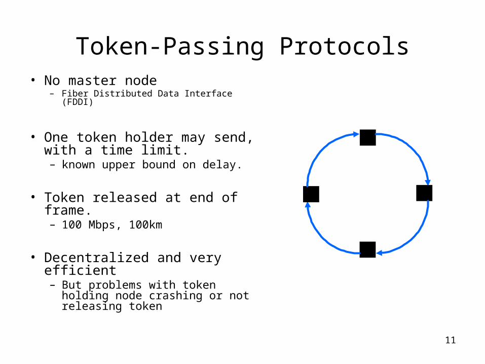
Token-Passing Protocols• No master node
– Fiber Distributed Data Interface (FDDI)
• One token holder may send, with a time limit. – known upper bound on delay.
• Token released at end of frame.– 100 Mbps, 100km
• Decentralized and very efficient– But problems with token holding
node crashing or not releasing token
12
This Lecture: IP addressing and Forwarding
13
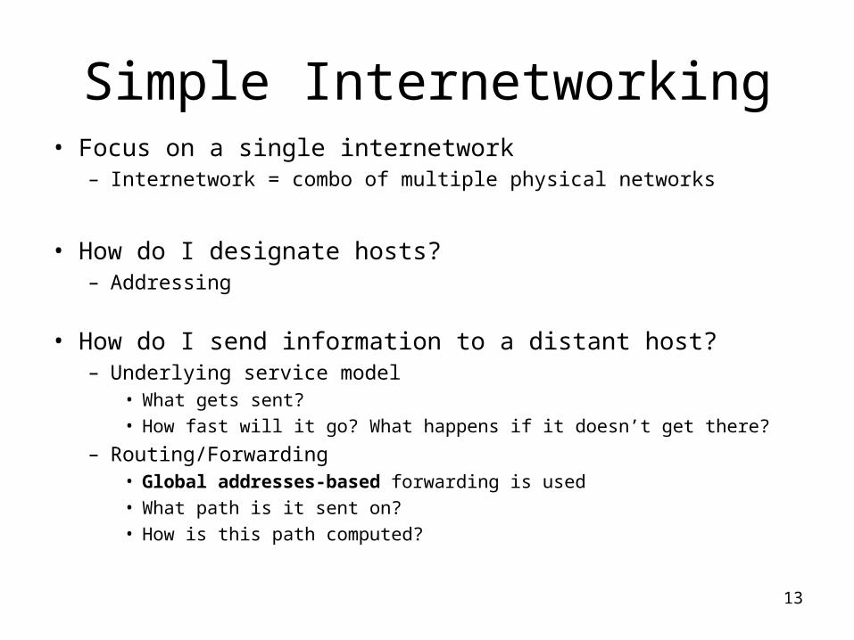
Simple Internetworking• Focus on a single internetwork
– Internetwork = combo of multiple physical networks
• How do I designate hosts?– Addressing
• How do I send information to a distant host?– Underlying service model
• What gets sent?• How fast will it go? What happens if it doesn’t get there?
– Routing/Forwarding• Global addresses-based forwarding is used• What path is it sent on?• How is this path computed?
14
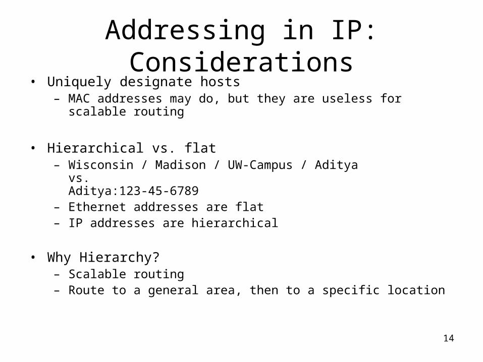
Addressing in IP: Considerations
• Uniquely designate hosts– MAC addresses may do, but they are useless for scalable
routing
• Hierarchical vs. flat– Wisconsin / Madison / UW-Campus / Aditya
vs. Aditya:123-45-6789
– Ethernet addresses are flat– IP addresses are hierarchical
• Why Hierarchy?– Scalable routing– Route to a general area, then to a specific location
15
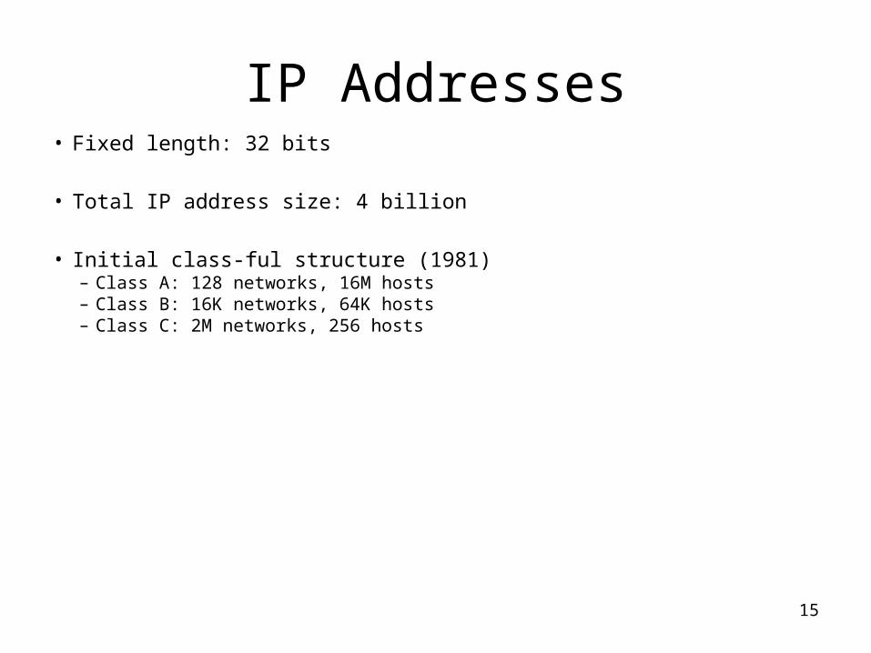
IP Addresses• Fixed length: 32 bits
• Total IP address size: 4 billion
• Initial class-ful structure (1981)– Class A: 128 networks, 16M hosts– Class B: 16K networks, 64K hosts– Class C: 2M networks, 256 hosts
16
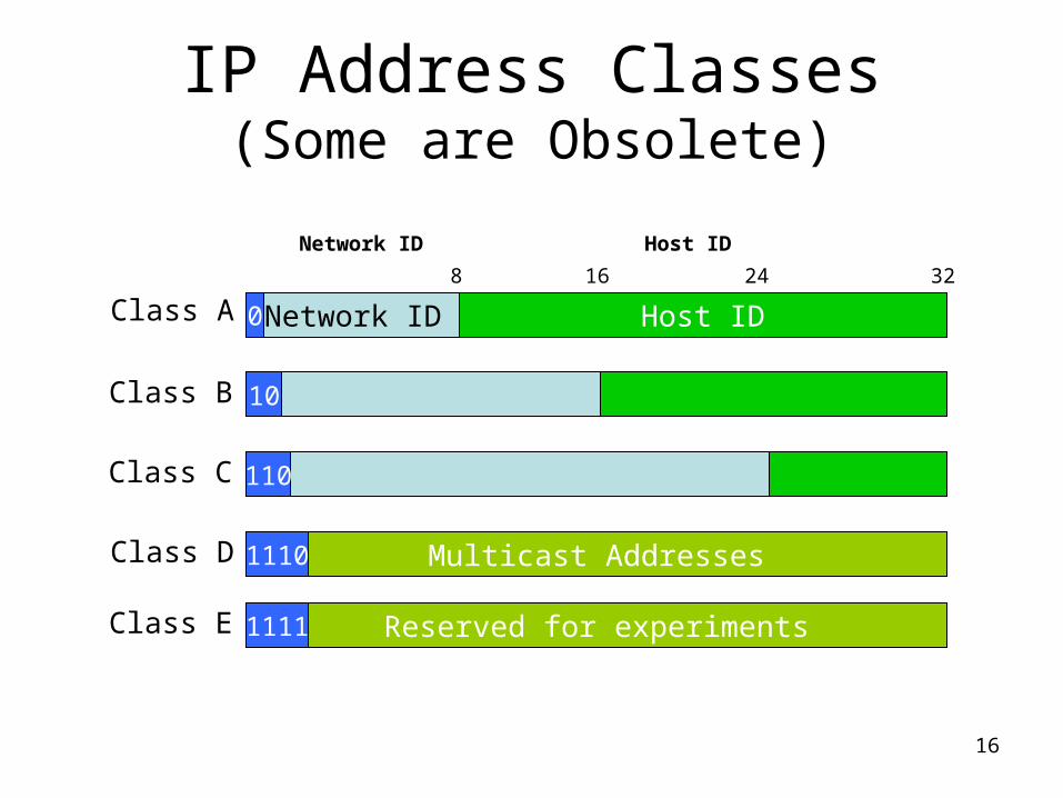
IP Address Classes(Some are Obsolete)
Network ID Host ID
Network ID Host ID
8 16
Class A32
0
Class B 10
Class C 110
Multicast AddressesClass D 1110
Reserved for experimentsClass E 1111
24
17
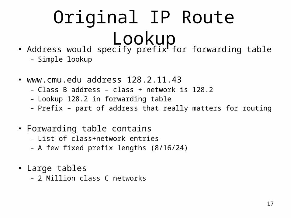
Original IP Route Lookup• Address would specify prefix for forwarding table
– Simple lookup
• www.cmu.edu address 128.2.11.43– Class B address – class + network is 128.2– Lookup 128.2 in forwarding table– Prefix – part of address that really matters for routing
• Forwarding table contains– List of class+network entries– A few fixed prefix lengths (8/16/24)
• Large tables– 2 Million class C networks
18
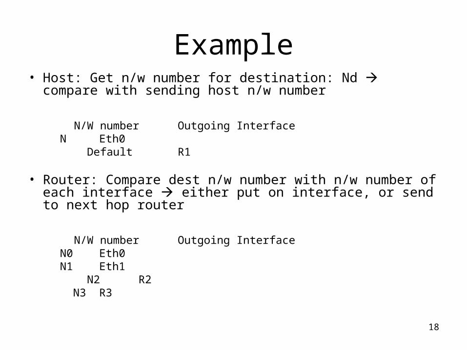
Example• Host: Get n/w number for destination: Nd compare
with sending host n/w number
N/W number Outgoing InterfaceN Eth0
Default R1
• Router: Compare dest n/w number with n/w number of each interface either put on interface, or send to next hop router
N/W number Outgoing InterfaceN0 Eth0N1 Eth1
N2 R2 N3 R3
19
Subnet Addressing: RFC917 (1984)
• Original goal: network part would uniquely identify a single physical network
• Inefficient address space usage– Class A & B networks too big
• Also, very few LANs have close to 64K hosts• Easy for networks to (claim to) outgrow class-C
– Each physical network must have one network number
• Routing table size is too high
• Need simple way to reduce the number of network numbers assigned– Subnetting: Split up single network address ranges– Fizes routing table size problem, partially
20
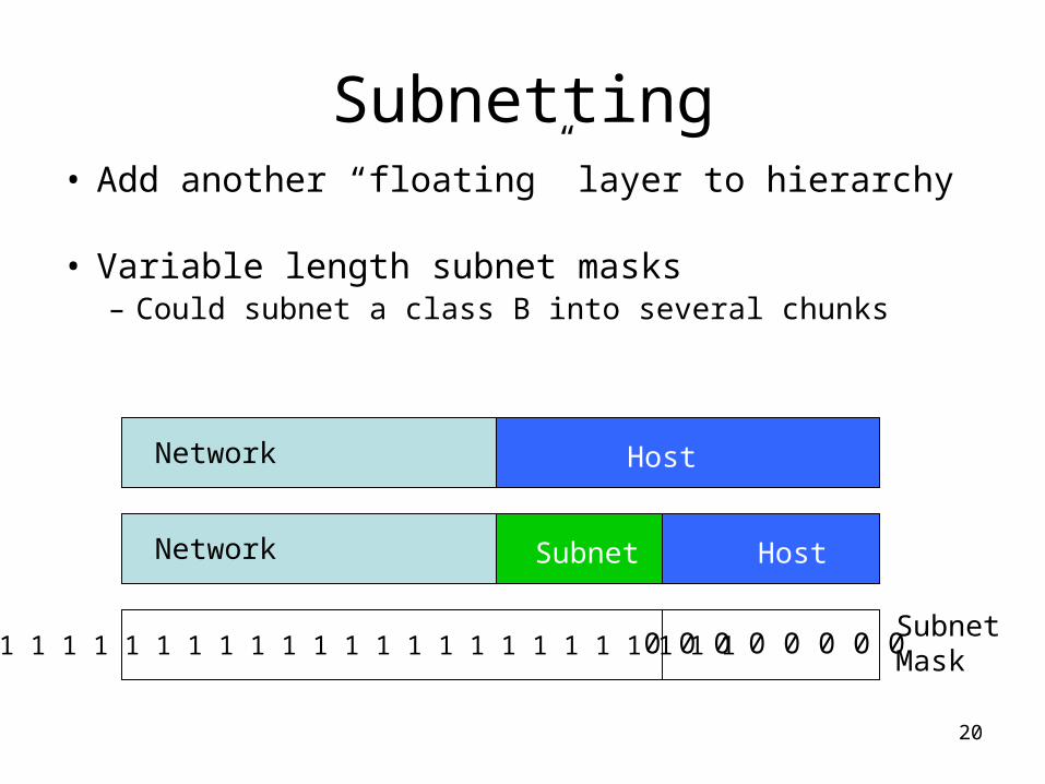
Subnetting• Add another “floating” layer to hierarchy
• Variable length subnet masks– Could subnet a class B into several chunks
Network Host
Network HostSubnet
1 1 1 1 1 1 1 1 1 1 1 1 1 1 1 1 1 1 1 1 1 1 1 1 0 0 0 0 0 0 0 0SubnetMask
21
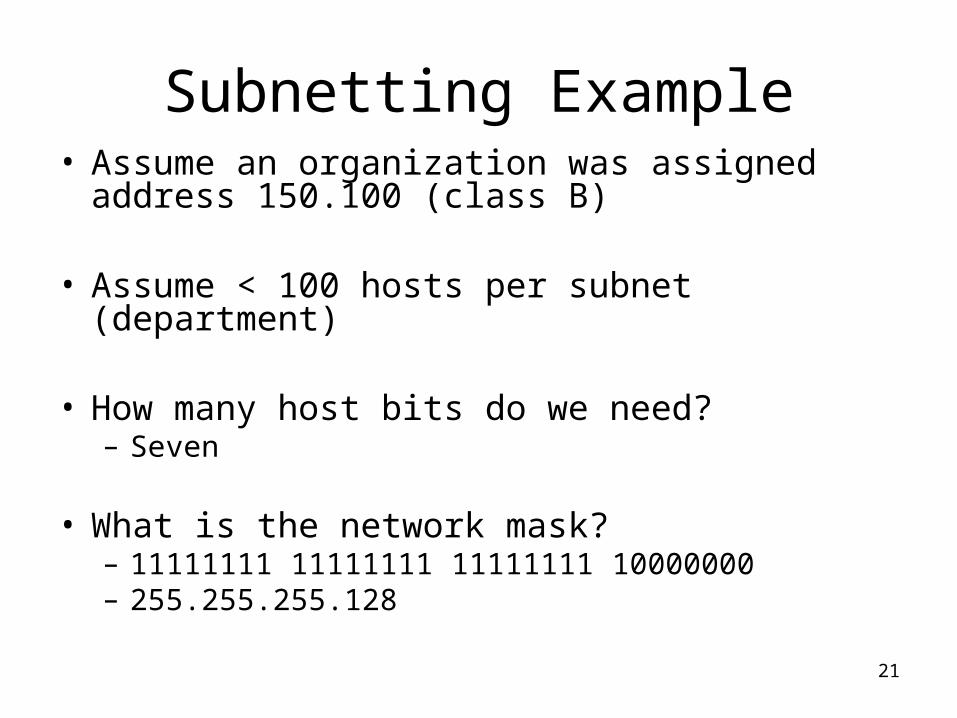
Subnetting Example• Assume an organization was assigned
address 150.100 (class B)
• Assume < 100 hosts per subnet (department)
• How many host bits do we need?– Seven
• What is the network mask?– 11111111 11111111 11111111 10000000– 255.255.255.128
22
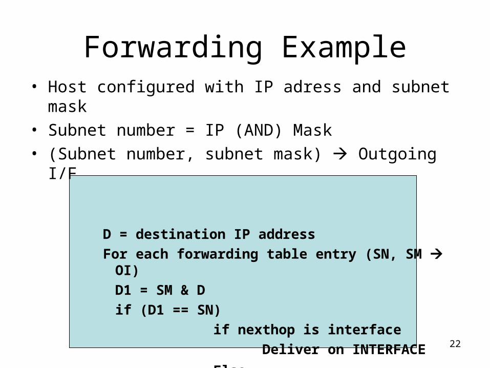
Forwarding Example• Host configured with IP adress and subnet mask• Subnet number = IP (AND) Mask• (Subnet number, subnet mask) Outgoing I/F
D = destination IP addressFor each forwarding table entry (SN, SM OI)
D1 = SM & Dif (D1 == SN)
if nexthop is interfaceDeliver on INTERFACE
Else
Forward to default router
23
Inefficient Address Usage• Address space depletion
– In danger of running out of classes A and B
– Why?• Class C too small for most domains• Very few class A – very careful about giving
them out• Class B poses greatest problem
– Class B sparsely populated • But people refuse to give it back
24
Classless Inter-Domain Routing(CIDR) – RFC1338
• Allows arbitrary split between network & host part of address – Do not use classes to determine network ID– Use common part of address as network number– Allows handing out arbitrary sized chunks of address
space– E.g., addresses 192.4.16 - 192.4.31 have the first 20 bits
in common. Thus, we use these 20 bits as the network number 192.4.16/20
• Enables more efficient usage of address space (and router tables)– Use single entry for range in forwarding tables– Combine forwarding entries when possible
25
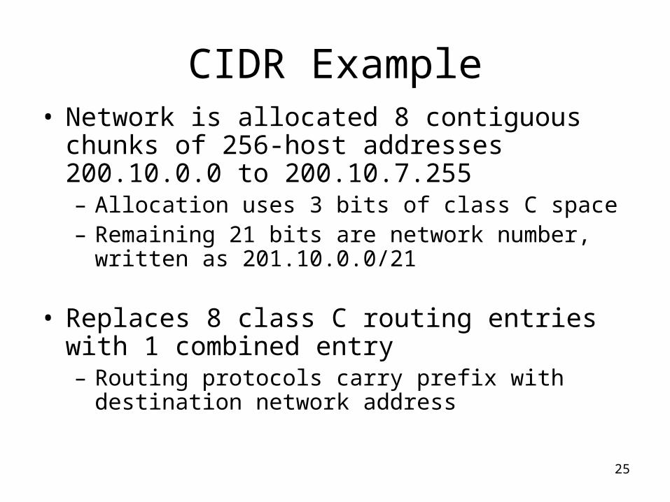
CIDR Example• Network is allocated 8 contiguous chunks
of 256-host addresses 200.10.0.0 to 200.10.7.255– Allocation uses 3 bits of class C space– Remaining 21 bits are network number, written
as 201.10.0.0/21
• Replaces 8 class C routing entries with 1 combined entry– Routing protocols carry prefix with destination
network address
26
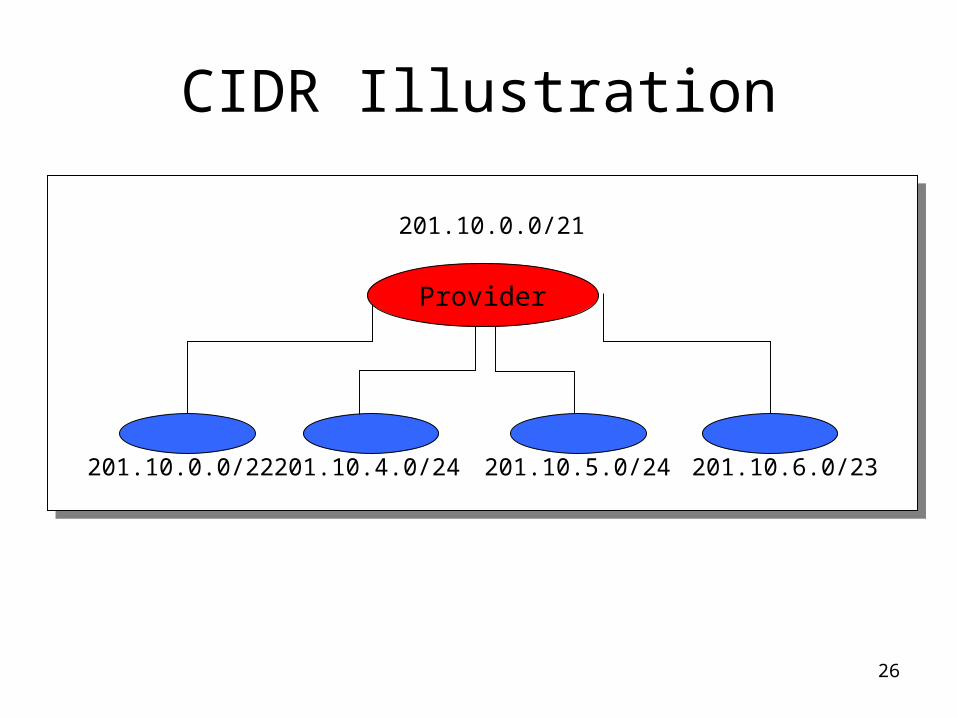
CIDR Illustration
201.10.0.0/21
201.10.0.0/22 201.10.4.0/24 201.10.5.0/24 201.10.6.0/23
Provider
27
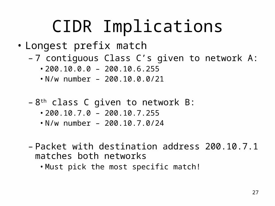
CIDR Implications• Longest prefix match
– 7 contiguous Class C’s given to network A:• 200.10.0.0 – 200.10.6.255• N/w number – 200.10.0.0/21
– 8th class C given to network B:• 200.10.7.0 – 200.10.7.255• N/w number – 200.10.7.0/24
– Packet with destination address 200.10.7.1 matches both networks• Must pick the most specific match!