Embed Size (px)
Citation preview

CS 61C L30 Verilog I (1) Garcia, Spring 2004 © UCB
Lecturer PSOE Dan Garcia
www.cs.berkeley.edu/~ddgarcia
inst.eecs.berkeley.edu/~cs61c CS61C : Machine Structures
Lecture 30 – Verilog I
2004-04-07
U Conn! Amazing hoop
story, never been done before. Both Men’s and
Women’s team win 2004 NCAA basketball
titles!Diana Taurasi for Prez!
CS 61C L30 Verilog I (2) Garcia, Spring 2004 © UCB
What about overflow?•Consider a 2-bit signed # & overflow:•10 = -2 + -2 or -1•11 = -1 + -2 only•00 = 0 NOTHING!•01 = 1 + 1 only
•Highest adder• C1 = Carry-in = Cin, C2 = Carry-out = Cout
• No Cout or Cin NO overflow!
• Cin, and Cout NO overflow!
• Cin, but no Cout A,B both > 0, overflow!
• Cout, but no Cin A,B both < 0, overflow!
± #
Whatop?
CS 61C L30 Verilog I (3) Garcia, Spring 2004 © UCB
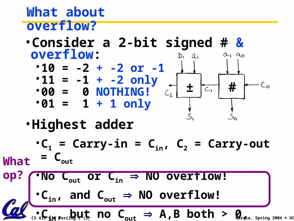
What about overflow?•Consider a 2-bit signed # & overflow:
10 = -2 + -2 or -111 = -1 + -2 only00 = 0 NOTHING!01 = 1 + 1 only
•Overflows when…• Cin, but no Cout A,B both > 0, overflow!
• Cout, but no Cin A,B both < 0, overflow!
± #
CS 61C L30 Verilog I (4) Garcia, Spring 2004 © UCB
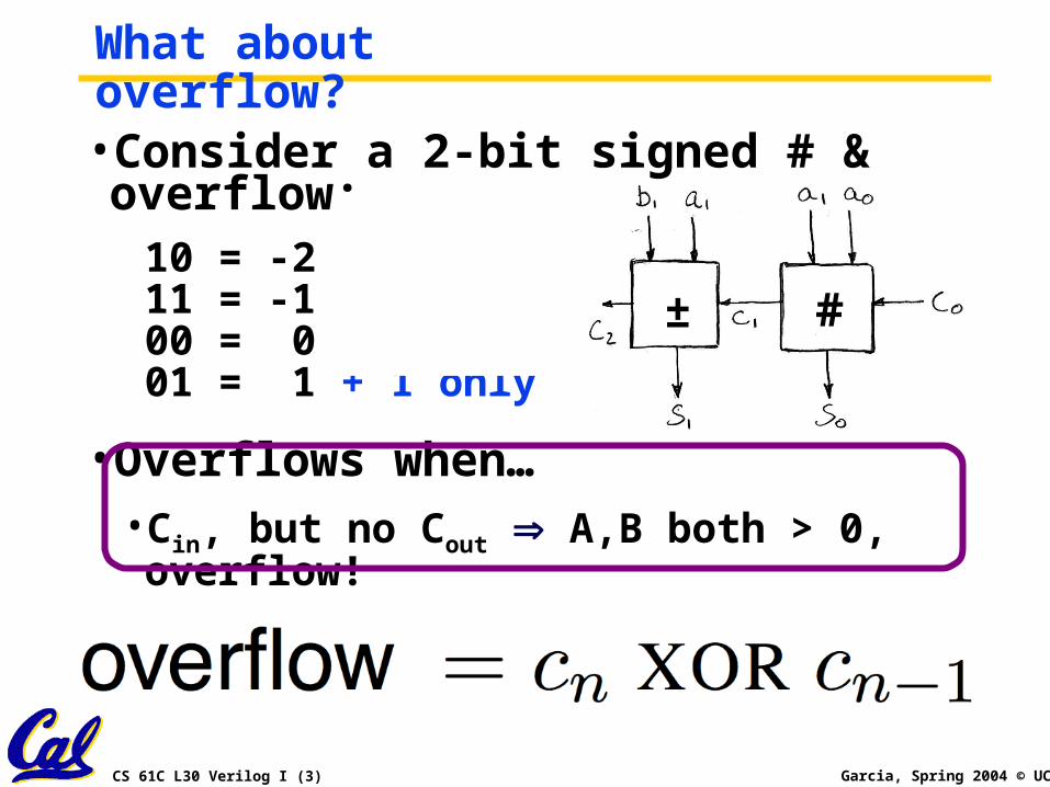
Extremely Clever Subtractor
What’s another way to say: A-B?A + (-B)How do we negate B?Complement and add 1 (conditional inv…)
CS 61C L30 Verilog I (5) Garcia, Spring 2004 © UCB
Peer Instruction
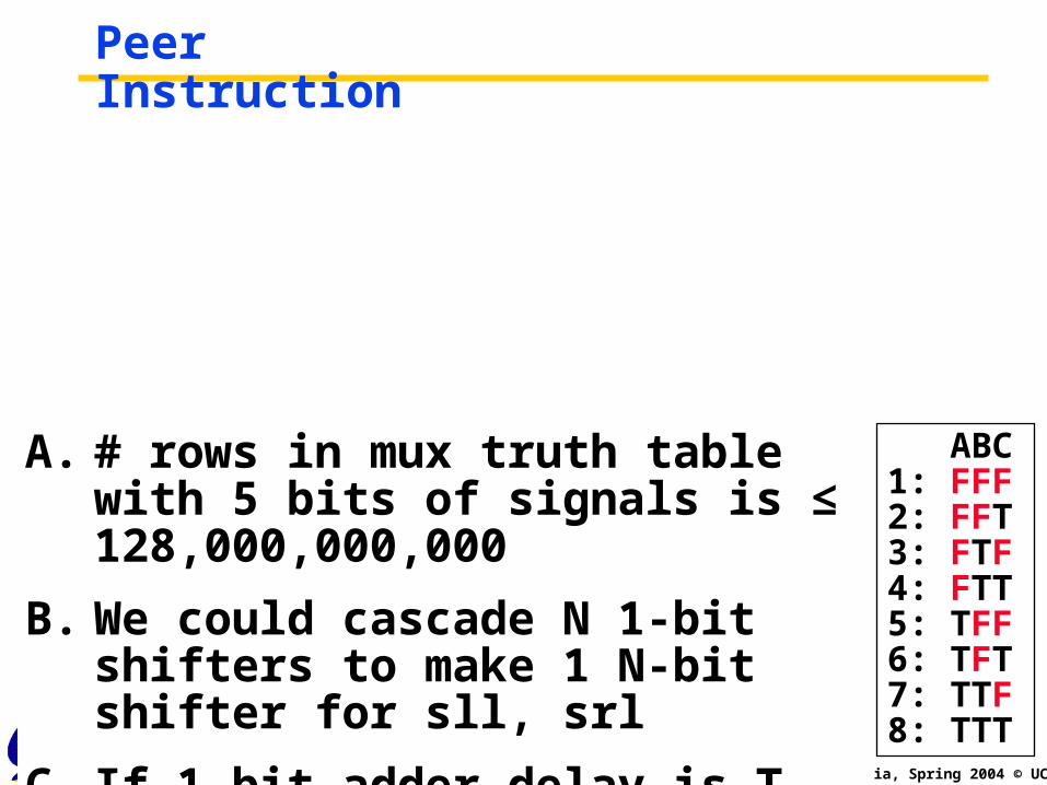
A. # rows in mux truth table with 5 bits of signals is ≤ 128,000,000,000
B. We could cascade N 1-bit shifters to make 1 N-bit shifter for sll, srl
C. If 1-bit adder delay is T, the N-bit adder delay would also be T
ABC1: FFF2: FFT 3: FTF4: FTT5: TFF6: TFT7: TTF8: TTT
CS 61C L30 Verilog I (6) Garcia, Spring 2004 © UCB
“And in semi-conclusion…”•Use muxes to select among input
• S input bits selects 2S inputs
• Each input can be n-bits wide, indep of S
• Implement muxes hierarchically
•ALU can be implemented using a mux• Coupled with basic block elements
•N-bit adder-subtractor done using N 1-bit adders with XOR gates on input• XOR serves as conditional inverter
CS 61C L30 Verilog I (7) Garcia, Spring 2004 © UCB
Administrivia•Reading quiz not up by 6pm; most did it, but it’ll officially be due Friday (there’s also the Friday Quiz too)
CS 61C L30 Verilog I (8) Garcia, Spring 2004 © UCB
Verilog Overview (1/3)•A Hardware Description Language (HDL) for describing & testing logic circuits.
• text based way to talk about designs• easier to simulate before silicon• translate into silicon directly
•No sequential execution, normally hardware just “runs” continuously.
•Verilog: A strange version of C, with some changes to account for time
• VHDL is alternative; similar and can pick it up easily. Verilog simpler to learn!
CS 61C L30 Verilog I (9) Garcia, Spring 2004 © UCB
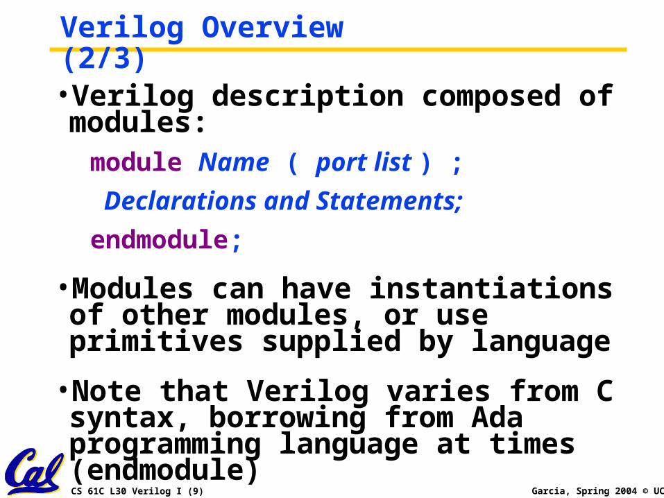
Verilog Overview (2/3)•Verilog description composed of modules:module Name ( port list ) ;
Declarations and Statements;
endmodule;
•Modules can have instantiations of other modules, or use primitives supplied by language
•Note that Verilog varies from C syntax, borrowing from Ada programming language at times (endmodule)
CS 61C L30 Verilog I (10) Garcia, Spring 2004 © UCB
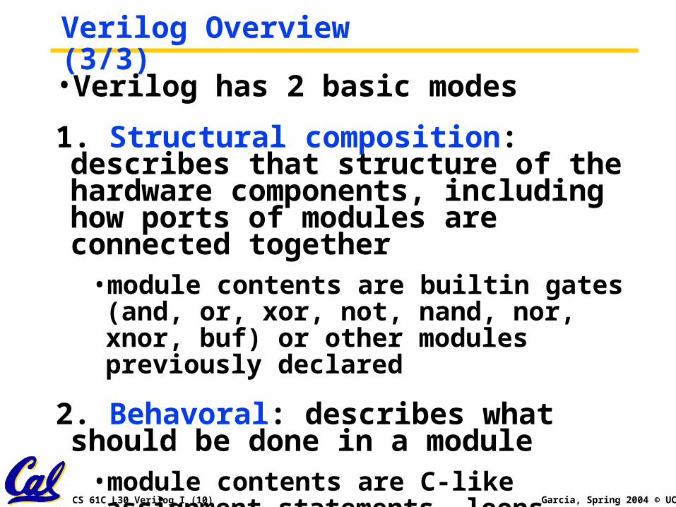
Verilog Overview (3/3)•Verilog has 2 basic modes
1. Structural composition: describes that structure of the hardware components, including how ports of modules are connected together
• module contents are builtin gates (and, or, xor, not, nand, nor, xnor, buf) or other modules previously declared
2. Behavoral: describes what should be done in a module
• module contents are C-like assignment statements, loops
CS 61C L30 Verilog I (11) Garcia, Spring 2004 © UCB
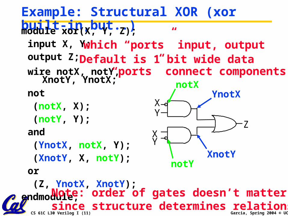
Example: Structural XOR (xor built-in,but..)module xor(X, Y, Z);input X, Y;output Z;
wire notX, notY, XnotY, YnotX;
not (notX, X); (notY, Y);and
(YnotX, notX, Y); (XnotY, X, notY);or
(Z, YnotX, XnotY);endmodule;
XY
XY
Z
XnotY
YnotXnotX
notY
which “ports” input, output
“ports” connect components
Note: order of gates doesn’t matter, since structure determines relationship
Default is 1 bit wide data
CS 61C L30 Verilog I (12) Garcia, Spring 2004 © UCB
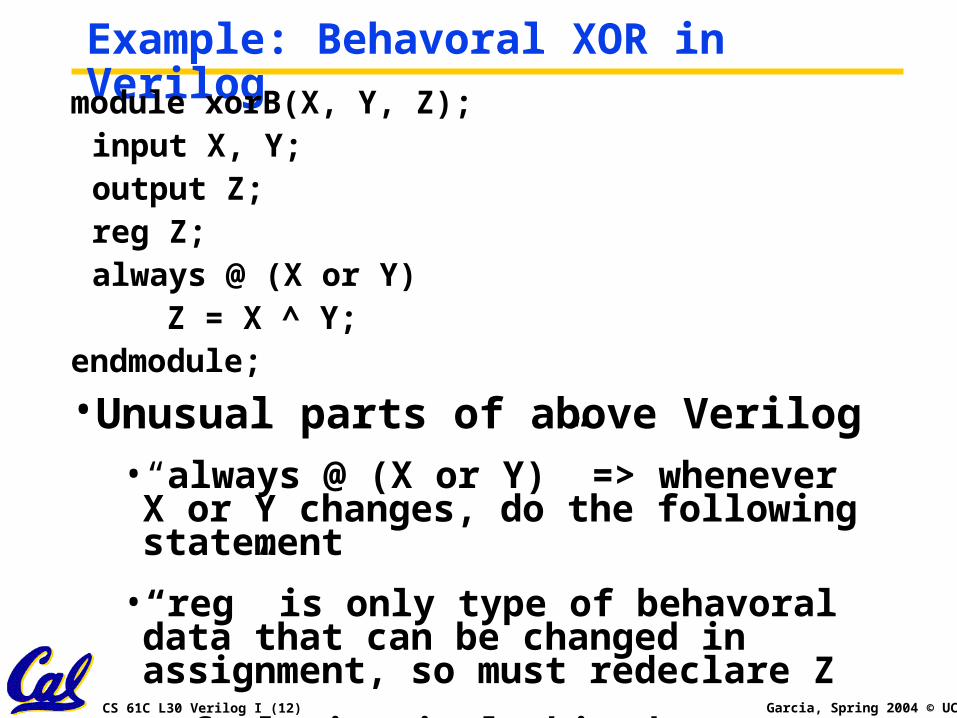
Example: Behavoral XOR in Verilog
module xorB(X, Y, Z);input X, Y;output Z;reg Z;always @ (X or Y)
Z = X ^ Y;endmodule;
•Unusual parts of above Verilog• “always @ (X or Y)” => whenever X or Y changes, do the following statement
• “reg” is only type of behavoral data that can be changed in assignment, so must redeclare Z
• Default is single bit data types: X, Y, Z
CS 61C L30 Verilog I (13) Garcia, Spring 2004 © UCB
Verilog: replication, hierarchy•Often in hardware need many copies of an item, connected together in a regular way
• Need way to name each copy
• Need way to specify how many copies
•Specify a module with 4 XORs using existing module example
CS 61C L30 Verilog I (14) Garcia, Spring 2004 © UCB
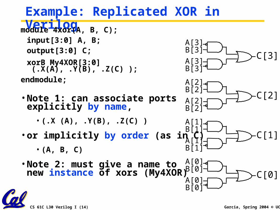
Example: Replicated XOR in Verilogmodule 4xor(A, B, C);input[3:0] A, B;output[3:0] C;
xorB My4XOR[3:0] (.X(A), .Y(B), .Z(C) );
endmodule;
• Note 1: can associate ports explicitly by name,
• (.X (A), .Y(B), .Z(C) )
• or implicitly by order (as in C)
• (A, B, C)
• Note 2: must give a name tonew instance of xors (My4XOR) C[0]
A[0]B[0]
A[0]B[0]
C[1]A[1]B[1]
A[1]B[1]
C[2]A[2]B[2]
A[2]B[2]
C[3]A[3]B[3]
A[3]B[3]
CS 61C L30 Verilog I (15) Garcia, Spring 2004 © UCB
Verilog big idea: Time•Difference from normal prog. lang. is that time is part of the language
• part of what trying to describe is when things occur, or how long things will take
• In both structural and behavoral Verilog, determine time with #n : event will take place in n time units
• structural: not #2(notX, X) says notX does not change until time advances 2 ns
• behavoral: Z = #2 A ^ B; says Z does not change until time advances 2 ns
• Default unit is nanoseconds; can change
CS 61C L30 Verilog I (16) Garcia, Spring 2004 © UCB
Example:
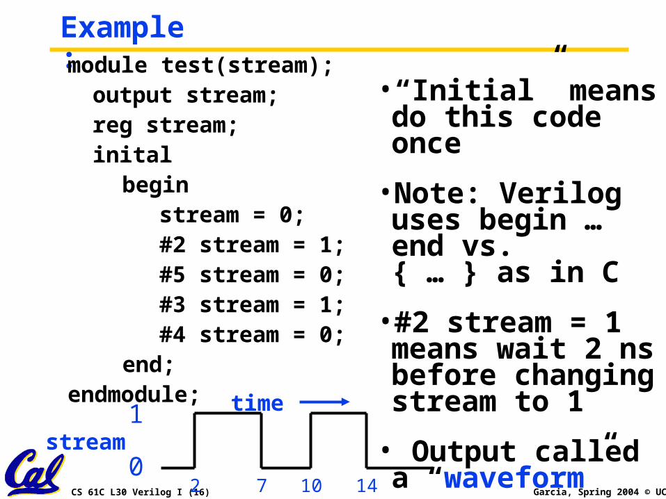
•“Initial” means do this code once
•Note: Verilog uses begin … end vs. { … } as in C
•#2 stream = 1 means wait 2 ns before changing stream to 1
• Output called a “waveform”
module test(stream);output stream;reg stream;inital
beginstream = 0;#2 stream = 1;#5 stream = 0;#3 stream = 1;#4 stream = 0;
end;endmodule;
stream0
1 time
2 7 10 14
CS 61C L30 Verilog I (17) Garcia, Spring 2004 © UCB
Testing in Verilog•Code above just defined a new module
•Need separate code to test the module (just like C/Java)
•Since hardware is hard to build, major emphasis on testing in HDL
•Testing modules called “test benches” in Verilog; like a bench in a lab dedicated to testing
•Can use time to say how things change
CS 61C L30 Verilog I (18) Garcia, Spring 2004 © UCB
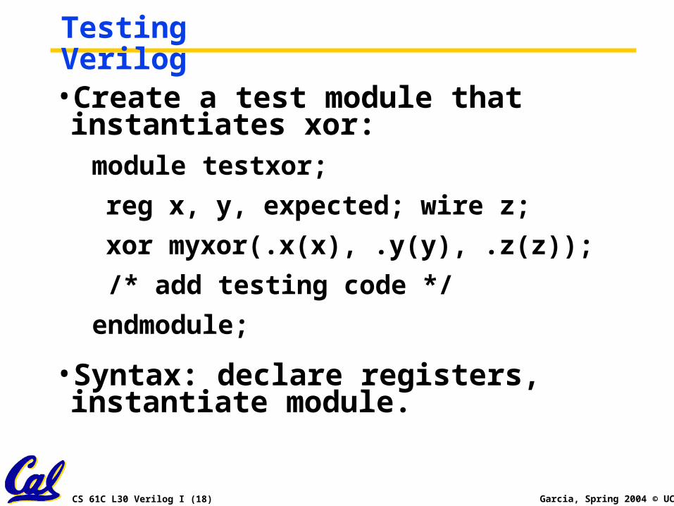
Testing Verilog•Create a test module that instantiates xor:module testxor;
reg x, y, expected; wire z;
xor myxor(.x(x), .y(y), .z(z));
/* add testing code */
endmodule;
•Syntax: declare registers, instantiate module.
CS 61C L30 Verilog I (19) Garcia, Spring 2004 © UCB
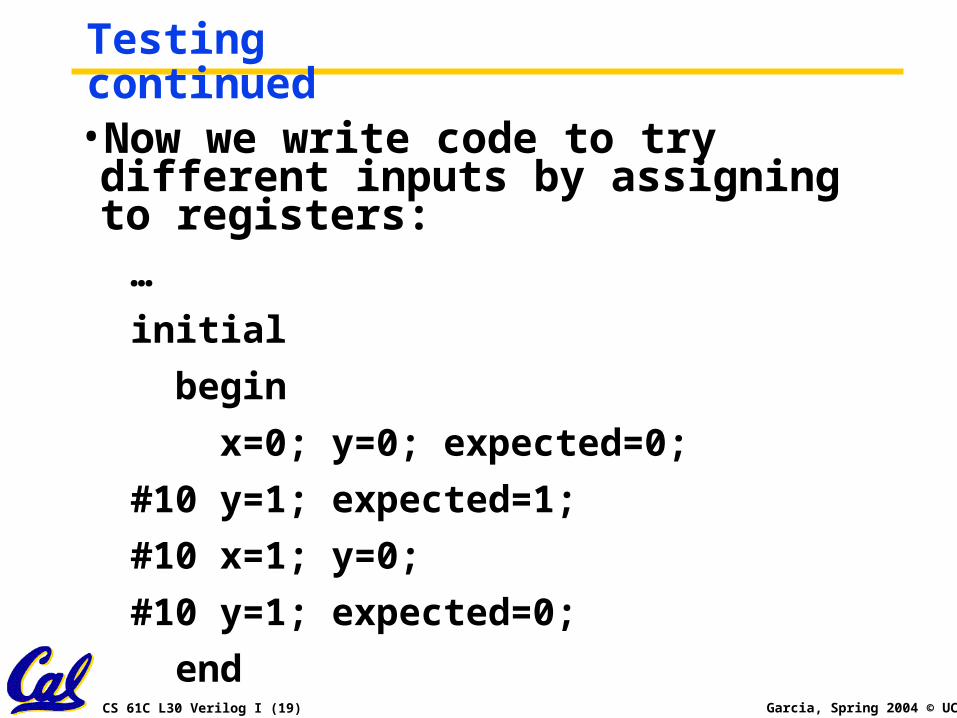
Testing continued•Now we write code to try different inputs by assigning to registers:…
initial
begin
x=0; y=0; expected=0;
#10 y=1; expected=1;
#10 x=1; y=0;
#10 y=1; expected=0;
end
CS 61C L30 Verilog I (20) Garcia, Spring 2004 © UCB
Testing continued•Pound sign syntax (#10) indicates code should wait simulated time (10 nanoseconds in this case).
•Values of registers can be changed with assignment statements.
•So far we have the xor module and a testxor module that iterates over all the inputs. How do we see if it is correct?
CS 61C L30 Verilog I (21) Garcia, Spring 2004 © UCB
Testing continued
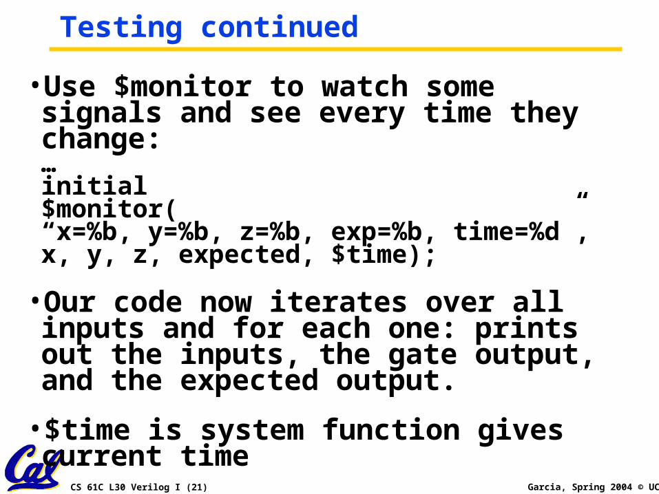
•Use $monitor to watch some signals and see every time they change:…initial$monitor(“x=%b, y=%b, z=%b, exp=%b, time=%d”,x, y, z, expected, $time);
•Our code now iterates over all inputs and for each one: prints out the inputs, the gate output, and the expected output.
•$time is system function gives current time
CS 61C L30 Verilog I (22) Garcia, Spring 2004 © UCB
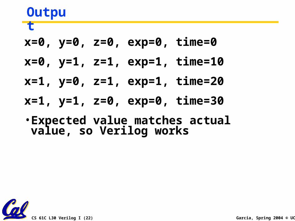
Outputx=0, y=0, z=0, exp=0, time=0
x=0, y=1, z=1, exp=1, time=10
x=1, y=0, z=1, exp=1, time=20
x=1, y=1, z=0, exp=0, time=30
• Expected value matches actual value, so Verilog works
CS 61C L30 Verilog I (23) Garcia, Spring 2004 © UCB
Peer Instruction
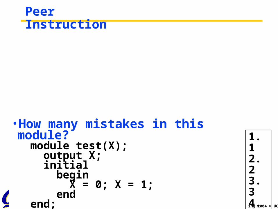
•How many mistakes in this module? module test(X); output X; initial begin X = 0; X = 1; end end;
1. 12. 23. 34. 45. 56. 0
CS 61C L30 Verilog I (25) Garcia, Spring 2004 © UCB
Peer Instruction
•Who’ll be the next apprentice?
1 2 3 4 5
Don’tcare/know
CS 61C L30 Verilog I (26) Garcia, Spring 2004 © UCB
In conclusion•Verilog allows both structural and behavioral descriptions, helpful in testing
•Syntax a mixture of C (operators, for, while, if, print) and Ada (begin… end, case…endcase, module …endmodule)
•Some special features only in Hardware Description Languages
• # time delay, initial vs. always
•Verilog can describe everything from single gate to full computer system; you get to design a simple processor