Embed Size (px)
Citation preview
CS 61C L15 Blocks (1) A Carle, Summer 2005 © UCB
inst.eecs.berkeley.edu/~cs61c/su05 CS61C : Machine Structures
Lecture #15: Combinational Logic Blocks
2005-07-14
Andy Carle
CS 61C L15 Blocks (2) A Carle, Summer 2005 © UCB
Outline•CL Blocks
•Latches & Flip Flops – A Closer Look
CS 61C L15 Blocks (3) A Carle, Summer 2005 © UCB
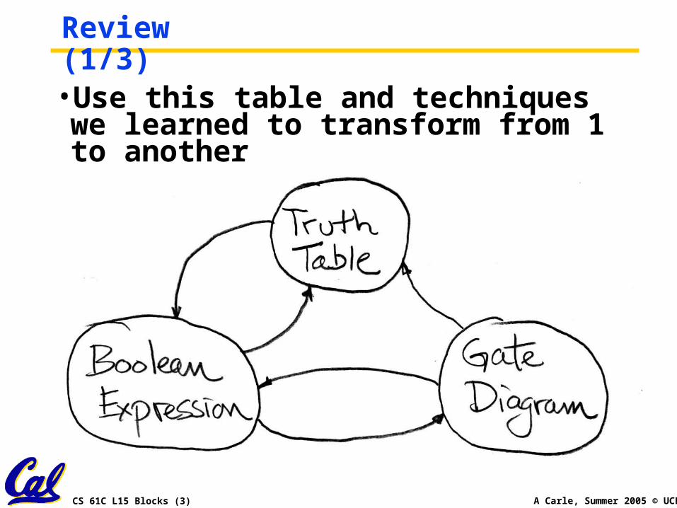
Review (1/3)•Use this table and techniques we learned to transform from 1 to another
CS 61C L15 Blocks (4) A Carle, Summer 2005 © UCB
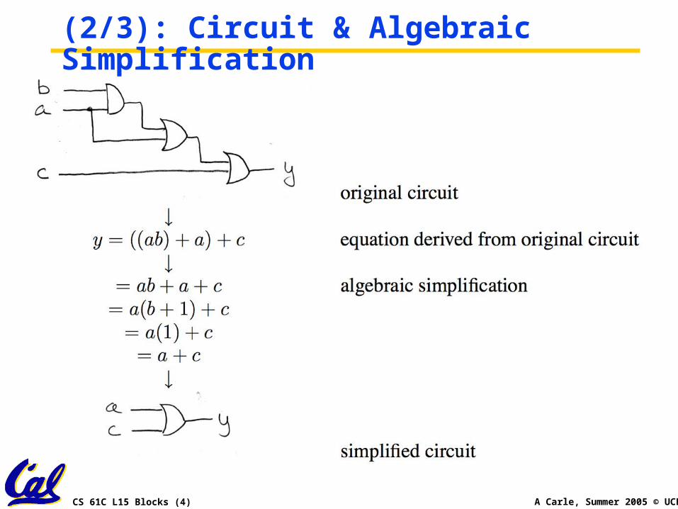
(2/3): Circuit & Algebraic Simplification
CS 61C L15 Blocks (5) A Carle, Summer 2005 © UCB
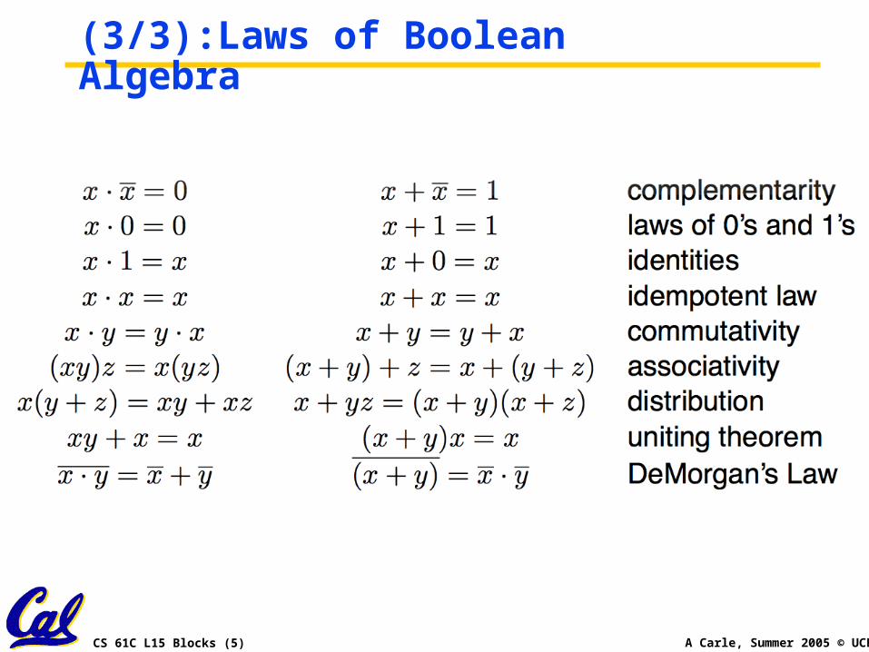
(3/3):Laws of Boolean Algebra
CS 61C L15 Blocks (6) A Carle, Summer 2005 © UCB
CL Blocks•Let’s use our skills to build some CL blocks:
• Multiplexer (mux)
• Adder
• ALU
CS 61C L15 Blocks (7) A Carle, Summer 2005 © UCB
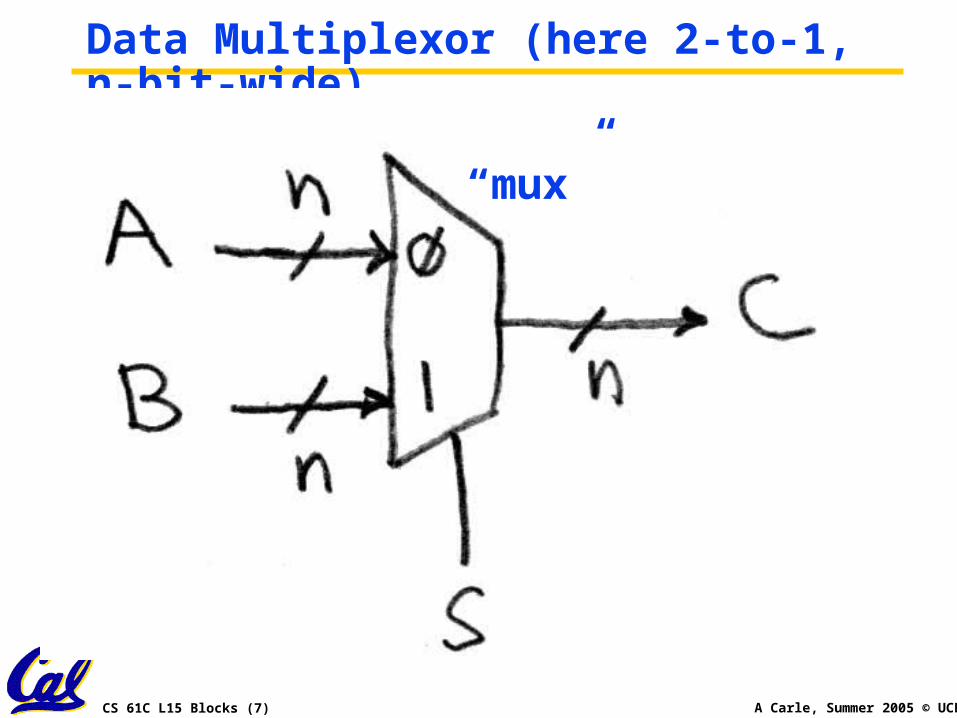
Data Multiplexor (here 2-to-1, n-bit-wide)
“mux”
CS 61C L15 Blocks (8) A Carle, Summer 2005 © UCB
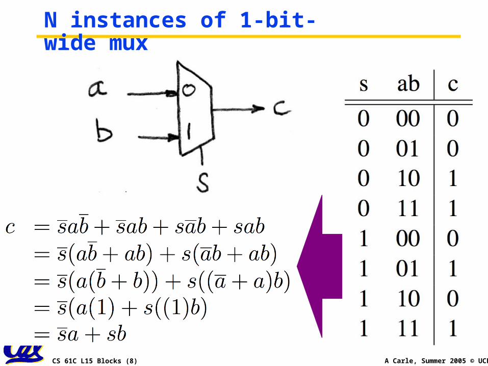
N instances of 1-bit-wide mux
CS 61C L15 Blocks (9) A Carle, Summer 2005 © UCB
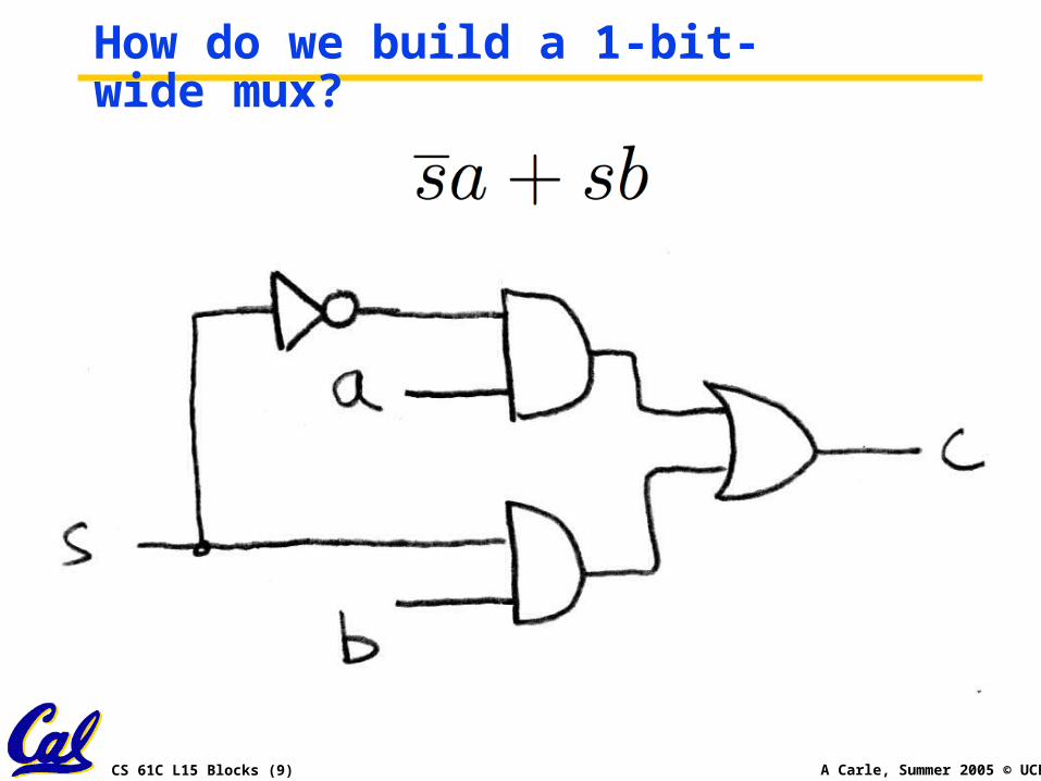
How do we build a 1-bit-wide mux?
CS 61C L15 Blocks (10) A Carle, Summer 2005 © UCB
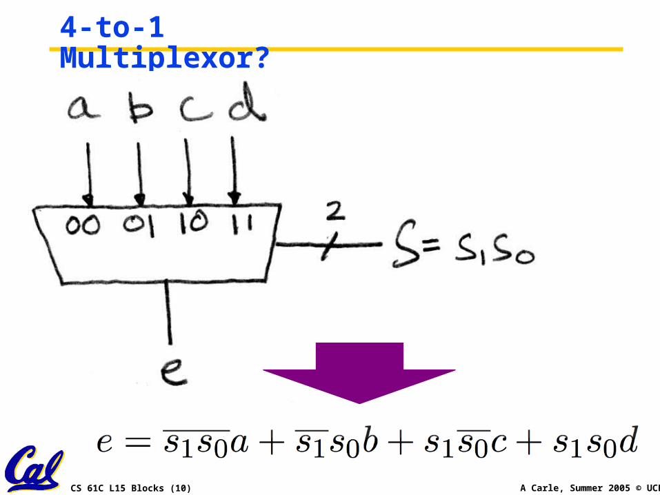
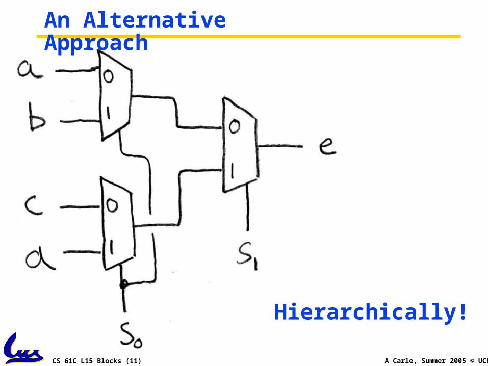
4-to-1 Multiplexor?
CS 61C L15 Blocks (11) A Carle, Summer 2005 © UCB
An Alternative Approach
Hierarchically!
CS 61C L15 Blocks (12) A Carle, Summer 2005 © UCB
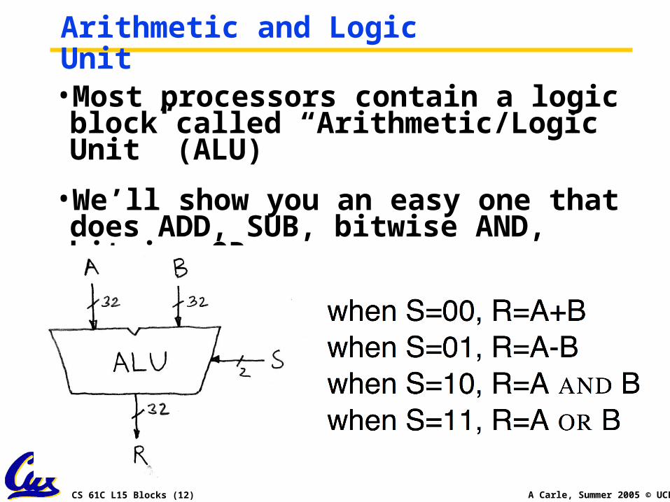
Arithmetic and Logic Unit•Most processors contain a logic block called “Arithmetic/Logic Unit” (ALU)
•We’ll show you an easy one that does ADD, SUB, bitwise AND, bitwise OR
CS 61C L15 Blocks (13) A Carle, Summer 2005 © UCB
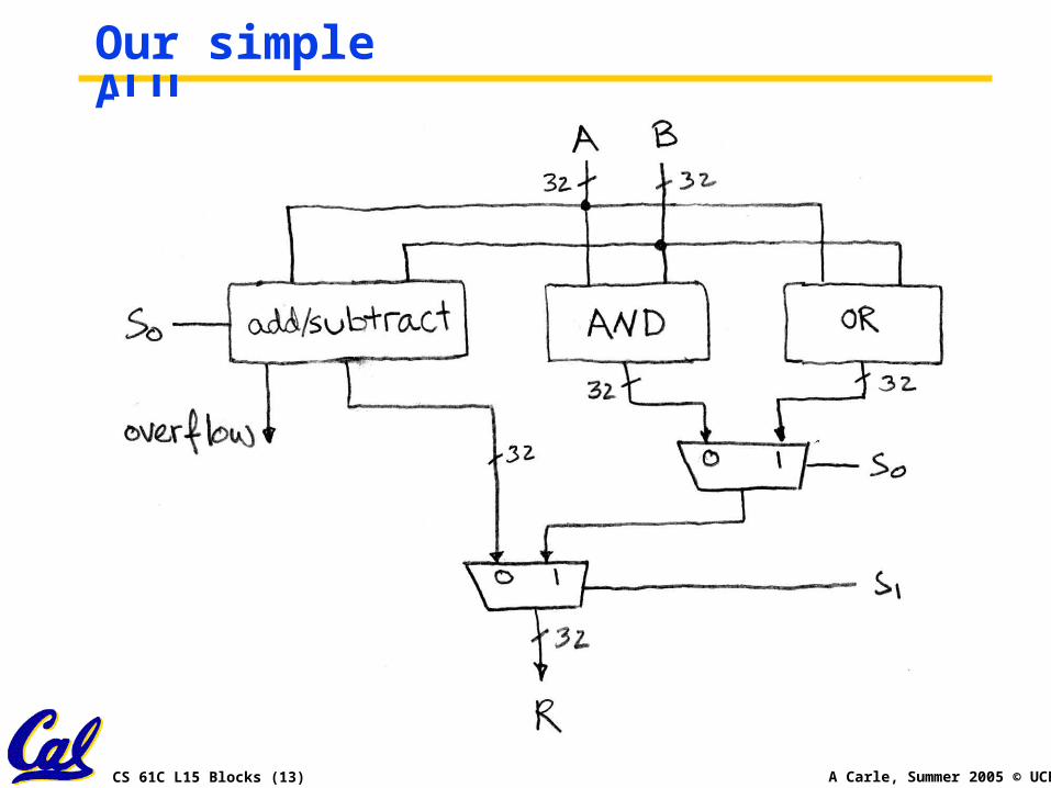
Our simple ALU
CS 61C L15 Blocks (14) A Carle, Summer 2005 © UCB
Adder/Subtracter Design -- how?• Truth-table, then
determine canonical form, then minimize and implement as we’ve seen before
• Look at breaking the problem down into smaller pieces that we can cascade or hierarchically layer
CS 61C L15 Blocks (15) A Carle, Summer 2005 © UCB
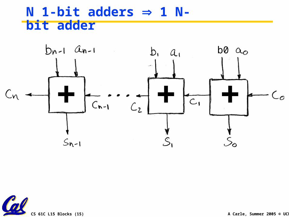
N 1-bit adders 1 N-bit adder
+ + +
b0
CS 61C L15 Blocks (16) A Carle, Summer 2005 © UCB
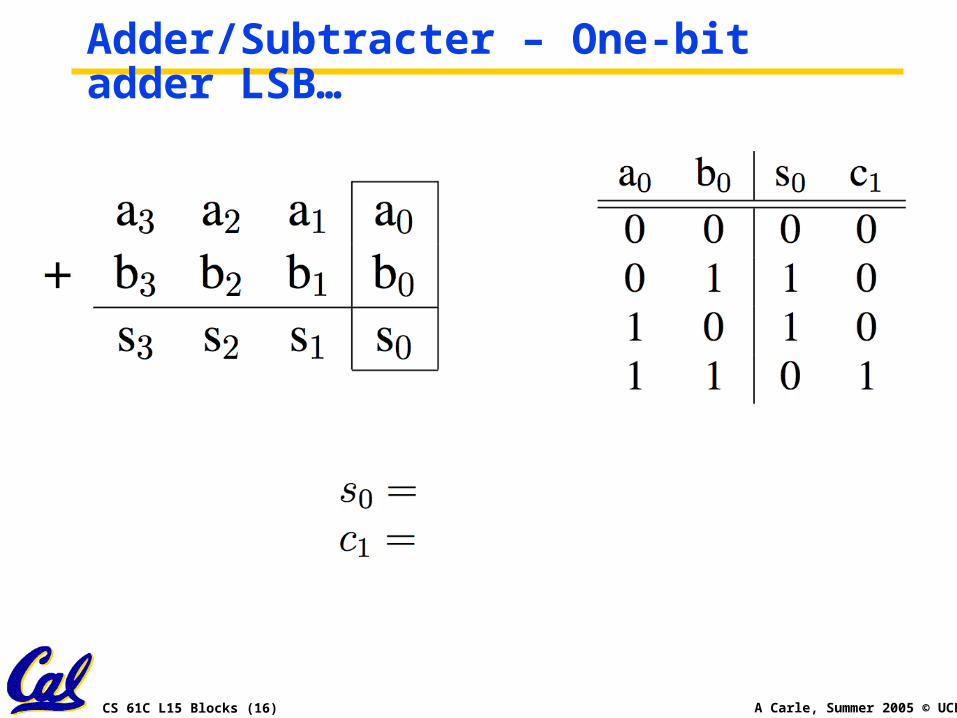
Adder/Subtracter – One-bit adder LSB…
CS 61C L15 Blocks (17) A Carle, Summer 2005 © UCB
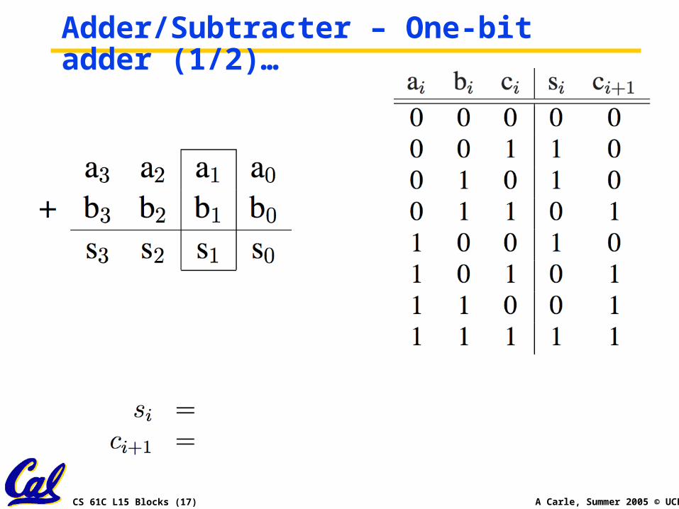
Adder/Subtracter – One-bit adder (1/2)…
CS 61C L15 Blocks (18) A Carle, Summer 2005 © UCB
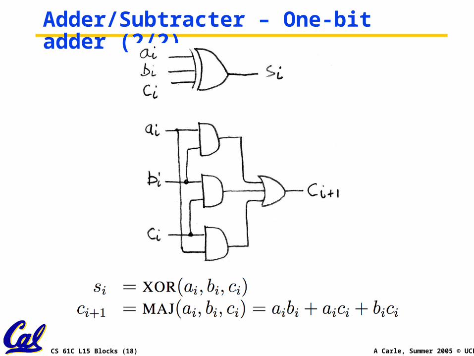
Adder/Subtracter – One-bit adder (2/2)…
CS 61C L15 Blocks (19) A Carle, Summer 2005 © UCB
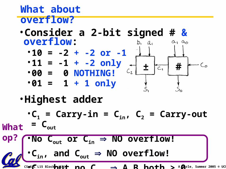
What about overflow?•Consider a 2-bit signed # & overflow:•10 = -2 + -2 or -1•11 = -1 + -2 only•00 = 0 NOTHING!•01 = 1 + 1 only
•Highest adder• C1 = Carry-in = Cin, C2 = Carry-out = Cout
• No Cout or Cin NO overflow!
• Cin, and Cout NO overflow!
• Cin, but no Cout A,B both > 0, overflow!
• Cout, but no Cin A,B both < 0, overflow!
± #
Whatop?
CS 61C L15 Blocks (20) A Carle, Summer 2005 © UCB
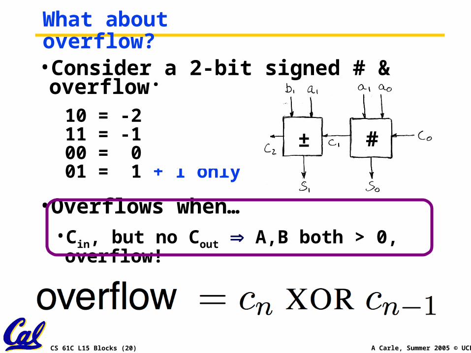
What about overflow?•Consider a 2-bit signed # & overflow:
10 = -2 + -2 or -111 = -1 + -2 only00 = 0 NOTHING!01 = 1 + 1 only
•Overflows when…• Cin, but no Cout A,B both > 0, overflow!
• Cout, but no Cin A,B both < 0, overflow!
± #
CS 61C L15 Blocks (21) A Carle, Summer 2005 © UCB
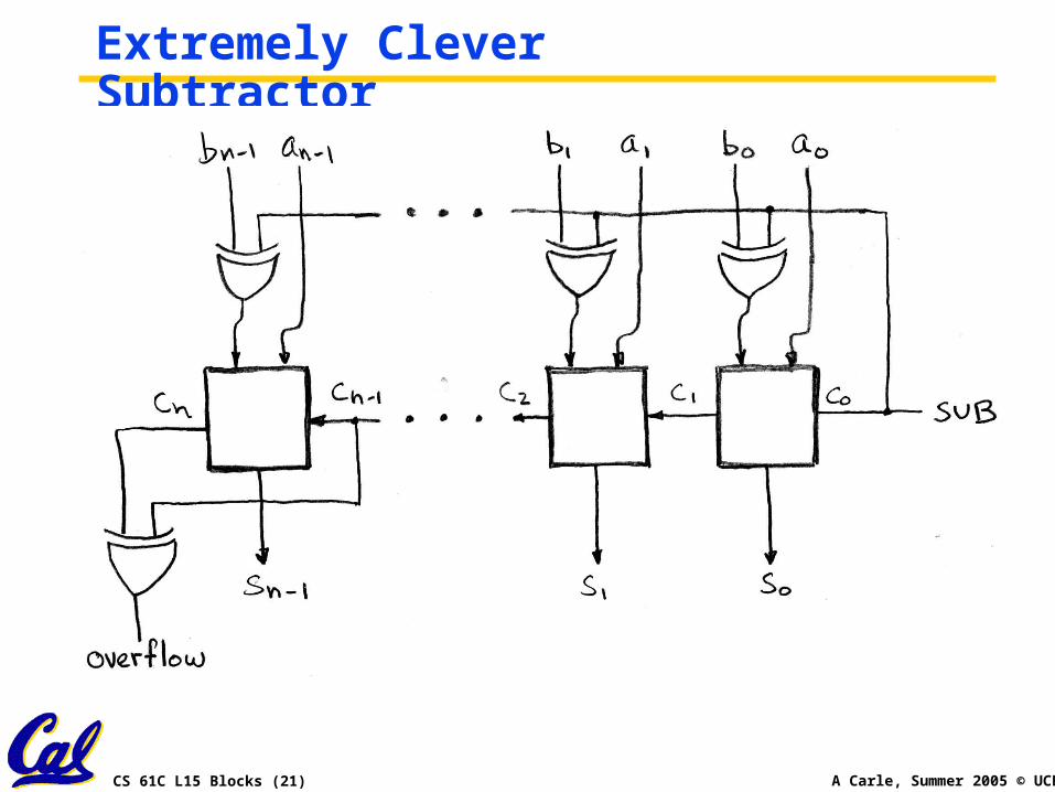
Extremely Clever Subtractor
CS 61C L15 Blocks (22) A Carle, Summer 2005 © UCB
Administrivia•We’re now halfway through the semester… yikes
•HW 45 Due Monday
•Proj2 coming…
•Logisim!
CS 61C L15 Blocks (23) A Carle, Summer 2005 © UCB
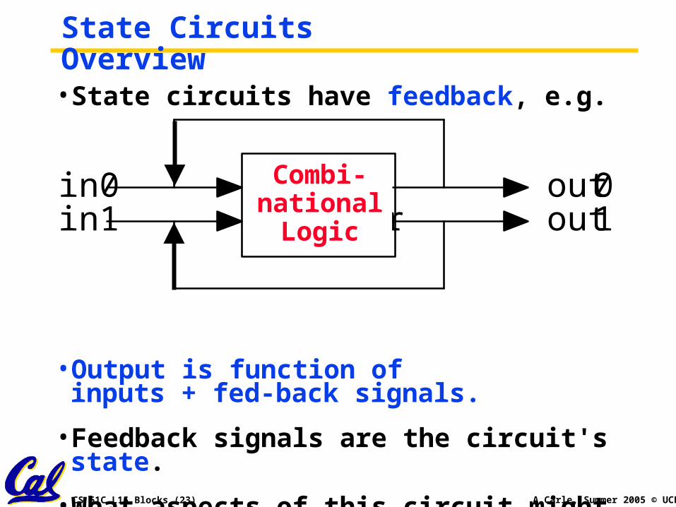
State Circuits Overview• State circuits have feedback, e.g.
•Output is function ofinputs + fed-back signals.
• Feedback signals are the circuit's state.
•What aspects of this circuit might cause complications?
lab 12 counter
in0in1
out0out1
Combi-national
Logic
CS 61C L15 Blocks (24) A Carle, Summer 2005 © UCB
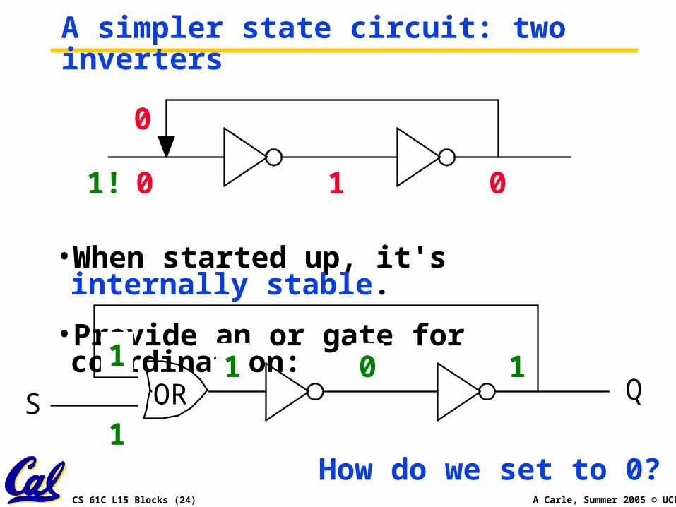
A simpler state circuit: two inverters
•When started up, it's internally stable.
•Provide an or gate for coordination:
•What's the result?
OR QS
0 1 0
0 1 0
0
0
0
1!
1
1 01 1
How do we set to 0?
CS 61C L15 Blocks (25) A Carle, Summer 2005 © UCB
0
Hold!
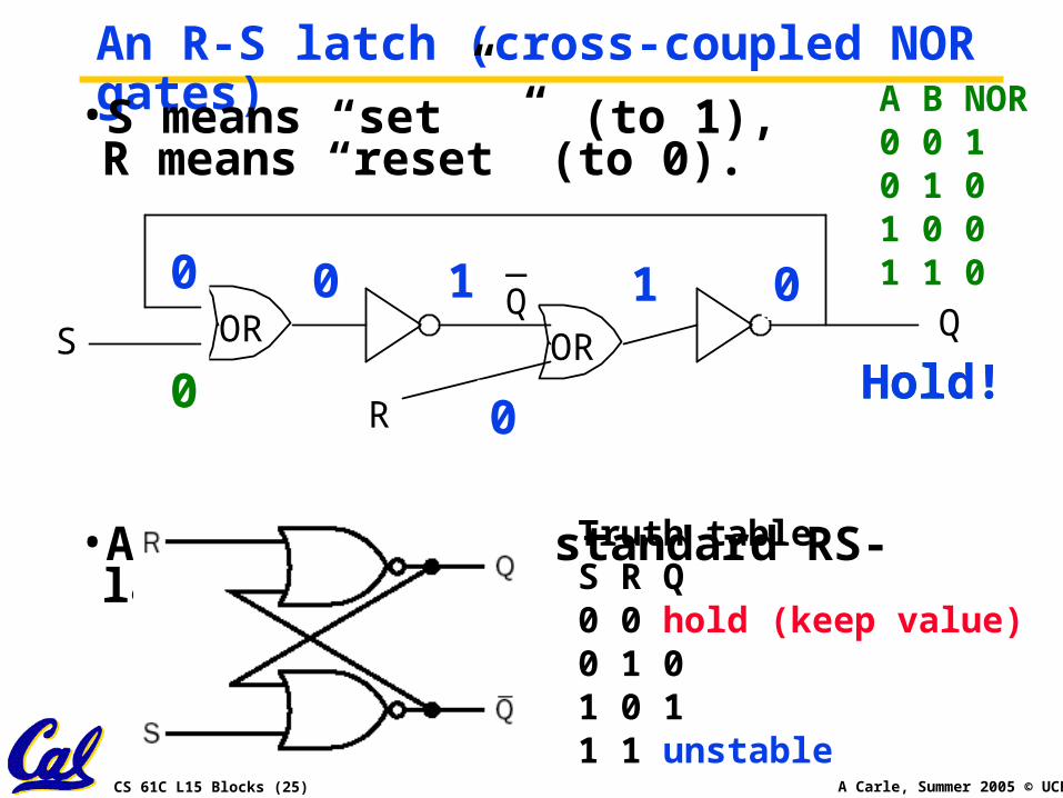
An R-S latch (cross-coupled NOR gates)•S means “set” (to 1),R means “reset” (to 0).
•Adding Q’ gives standard RS-latch:
OR ORS Q
R
Truth tableS R Q0 0 hold (keep value) 0 1 01 0 11 1 unstable
A B NOR0 0 10 1 01 0 01 1 0_
Q0 1 0
0
0
1
1 01 110
0
0 10 01
01
Hold!0
CS 61C L15 Blocks (26) A Carle, Summer 2005 © UCB
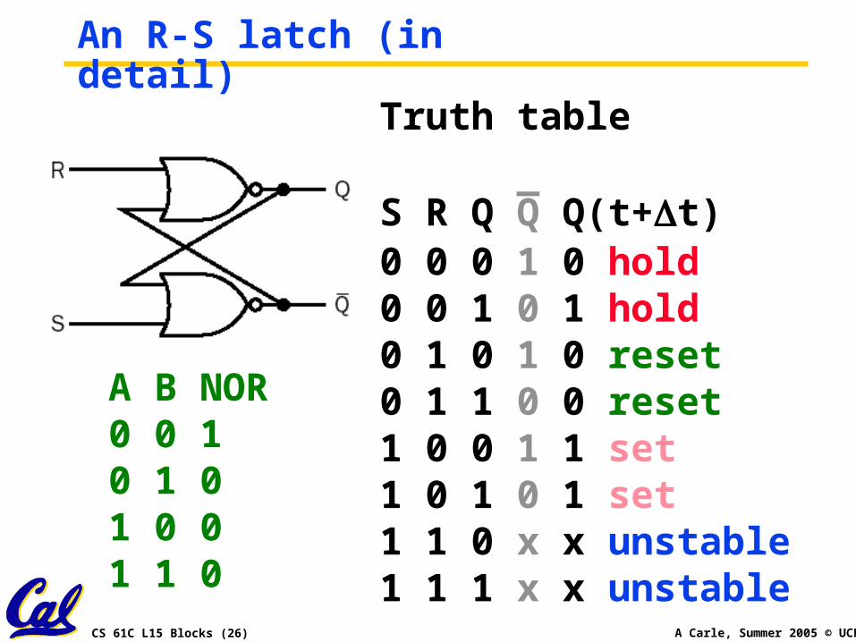
An R-S latch (in detail)
Truth table
_S R Q Q Q(t+t)0 0 0 1 0 hold0 0 1 0 1 hold0 1 0 1 0 reset0 1 1 0 0 reset1 0 0 1 1 set1 0 1 0 1 set1 1 0 x x unstable1 1 1 x x unstable
A B NOR0 0 10 1 01 0 01 1 0
CS 61C L15 Blocks (27) A Carle, Summer 2005 © UCB
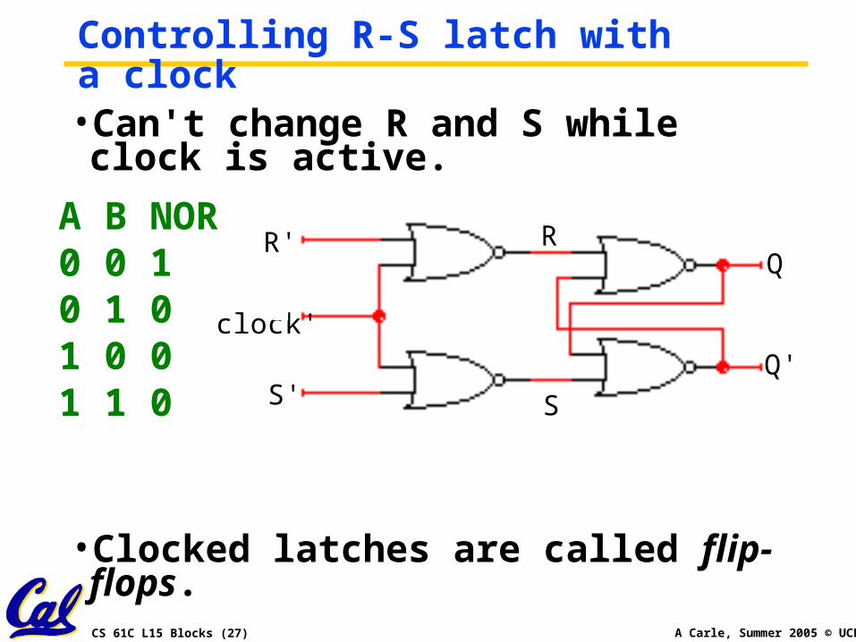
Controlling R-S latch with a clock•Can't change R and S while clock is active.
•Clocked latches are called flip-flops.
clock'
S'Q'
QR' R
S
A B NOR0 0 10 1 01 0 01 1 0
CS 61C L15 Blocks (28) A Carle, Summer 2005 © UCB
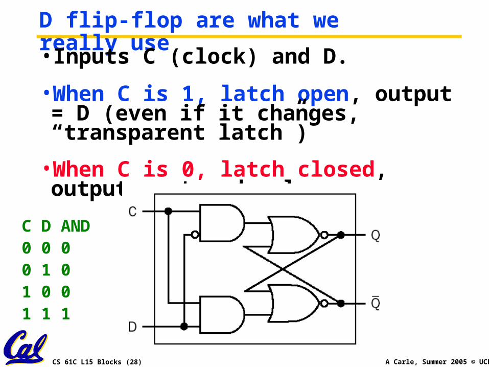
D flip-flop are what we really use• Inputs C (clock) and D.
•When C is 1, latch open, output = D (even if it changes, “transparent latch”)
•When C is 0, latch closed, output = stored value.
C D AND0 0 00 1 01 0 01 1 1
CS 61C L15 Blocks (29) A Carle, Summer 2005 © UCB
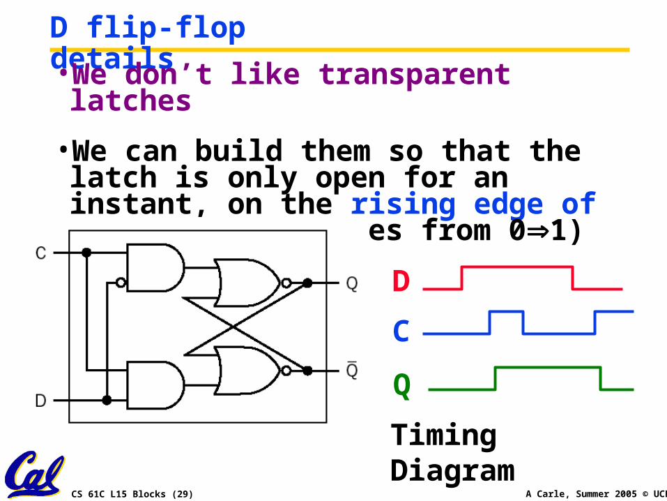
D flip-flop details•We don’t like transparent latches
•We can build them so that the latch is only open for an instant, on the rising edge of a clock (as it goes from 01)
D
C
Q
Timing Diagram
CS 61C L15 Blocks (30) A Carle, Summer 2005 © UCB
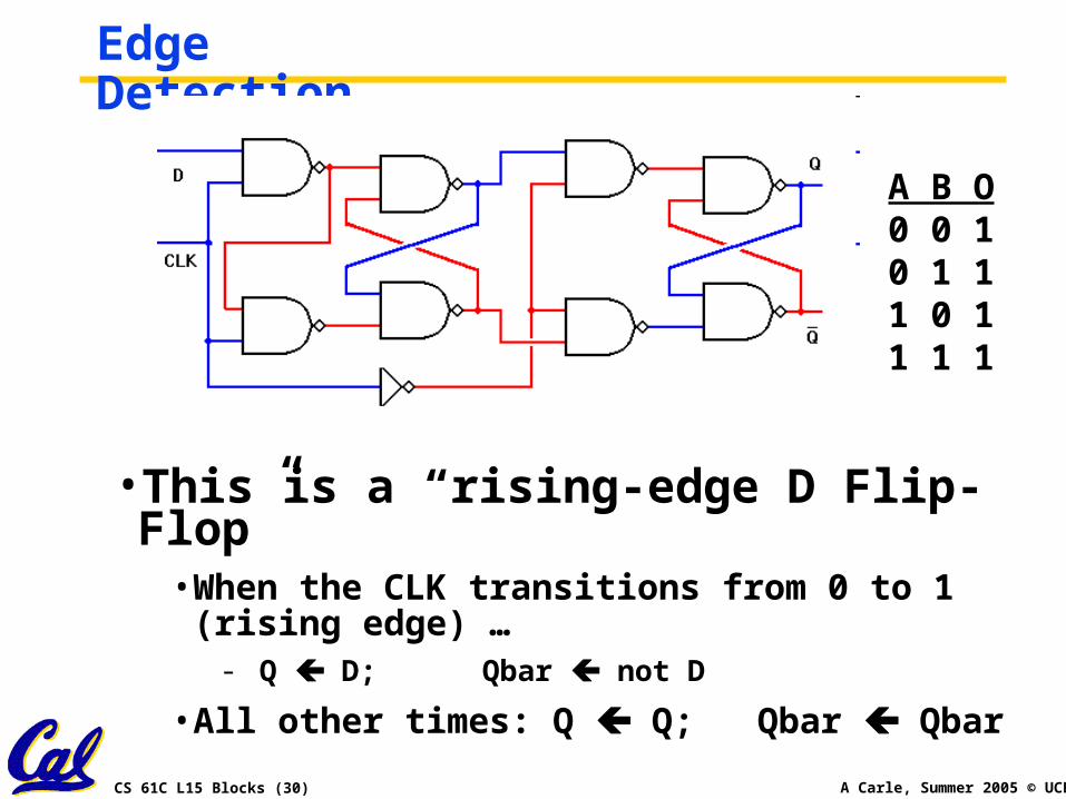
Edge Detection
•This is a “rising-edge D Flip-Flop”• When the CLK transitions from 0 to 1 (rising
edge) …- Q D; Qbar not D
• All other times: Q Q; Qbar Qbar
A B O0 0 10 1 11 0 11 1 1
CS 61C L15 Blocks (31) A Carle, Summer 2005 © UCB
Peer Instruction
A. Truth table for mux with 4 control signals has 24 rows
B. We could cascade N 1-bit shifters to make 1 N-bit shifter for sll, srl
C. If 1-bit adder delay is T, the N-bit adder delay would also be T
CS 61C L15 Blocks (32) A Carle, Summer 2005 © UCB
“And In conclusion…”•Use muxes to select among input
• S input bits selects 2S inputs
• Each input can be n-bits wide, indep of S
• Implement muxes hierarchically
•ALU can be implemented using a mux• Coupled with basic block elements
•N-bit adder-subtractor done using N 1-bit adders with XOR gates on input
• XOR serves as conditional inverter