Embed Size (px)
Citation preview

CS 6143 COMPUTER ARCHITECTURE II SPRING 2014
HOMEWORK III
NYU School of Engineering Page 1 of 22 Handout No : 6 February 26, 2014
DUE : By 6 PM, Monday, March 10, 2014
READ : - Related portions of Chapters 2, 3, 4 and Appendces A, B, C, G and H of the Hennessy book- Related portions of Chapter 7 of the Jordan book
ASSIGNMENT: There are three problems two of which are developed from the Hennessy book.
Solve all homework and exam problems as shown in class and past exam solutions
1) Consider the piece of code studied in Problem 3 of Homework I. This code is for the DAXPYapplication we discussed in class :
Assume that the MIPS is implemented as the 2-way superscalar hardware-speculative Toma-sulo algorithm machine as discussed in class. That is, this is machine model number 5. A pair ofinstructions is issued per cycle, provided that static issuing is preserved. Two (2) instructions canbe committed in order per cycle provided that they are at the head of the ROB.
a) Assume also that the functional unit timings are as listed on page C-77 of the Hennessy book ;the number of reservation station buffers for FP operations is as given in class ; the number ofCDB buses is as given class ; there is a Branch Unit in the EX stage for calculating its effectiveaddress and determining the condition ; there is also additional branch prediction hardware in andout of the pipeline ; there are enough functional units for integer instructions not to cause stalls ;the L1 cache memories take one clock period each and there are no cache misses : There is anideal memory
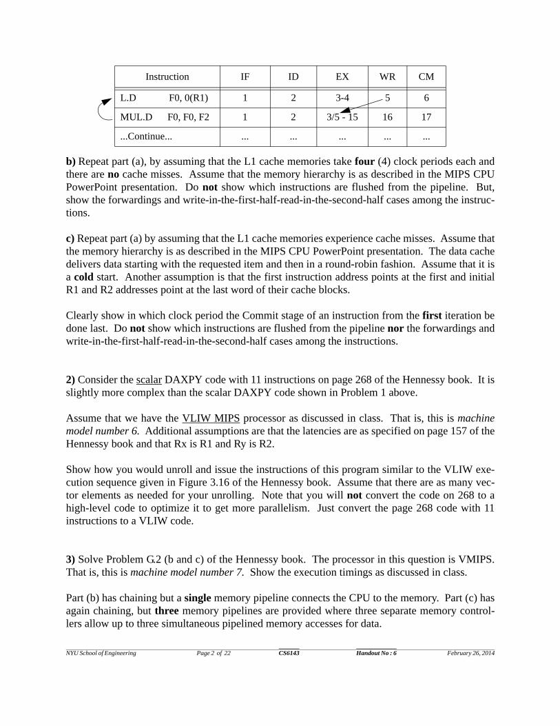
Assume that there is only one iteration. Then, in which clock period, will the first iteration of theabove loop be completed ? That is, what is the last clock period in which the Commit stage of aninstruction from the first iteration be done last ? Also, show which instructions are flushed out ofthe pipeline. Indicate any assumptions made during the execution of the loop, if a situation notdiscussed in class is encountered. To answer it, continue the following table :
loop : L.D F0, 0(R1) ; load X[i]MUL.D F0, F0, F2 ; multiply a * X[i]L.D F4, 0(R2) ; load Y[i]ADD.D F0, F0, F4 ; add a * X[i[ + Y[i]S.D F0, 0(R2) ; store Y[i]DADDI R1, R1, #(-8)10 ; decrement X indexDADDI R2, R2, #(-8)10 ; decrement Y indexBNEZ R1, loop ; loop if not done
NYU School of Engineering Page 2 of 22 CS6143 Handout No : 6 February 26, 2014
b) Repeat part (a), by assuming that the L1 cache memories take four (4) clock periods each andthere are no cache misses. Assume that the memory hierarchy is as described in the MIPS CPUPowerPoint presentation. Do not show which instructions are flushed from the pipeline. But,show the forwardings and write-in-the-first-half-read-in-the-second-half cases among the instruc-tions.
c) Repeat part (a) by assuming that the L1 cache memories experience cache misses. Assume thatthe memory hierarchy is as described in the MIPS CPU PowerPoint presentation. The data cachedelivers data starting with the requested item and then in a round-robin fashion. Assume that it isa cold start. Another assumption is that the first instruction address points at the first and initialR1 and R2 addresses point at the last word of their cache blocks.
Clearly show in which clock period the Commit stage of an instruction from the first iteration bedone last. Do not show which instructions are flushed from the pipeline nor the forwardings andwrite-in-the-first-half-read-in-the-second-half cases among the instructions.
2) Consider the scalar DAXPY code with 11 instructions on page 268 of the Hennessy book. It isslightly more complex than the scalar DAXPY code shown in Problem 1 above.
Assume that we have the VLIW MIPS processor as discussed in class. That is, this is machinemodel number 6. Additional assumptions are that the latencies are as specified on page 157 of theHennessy book and that Rx is R1 and Ry is R2.
Show how you would unroll and issue the instructions of this program similar to the VLIW exe-cution sequence given in Figure 3.16 of the Hennessy book. Assume that there are as many vec-tor elements as needed for your unrolling. Note that you will not convert the code on 268 to ahigh-level code to optimize it to get more parallelism. Just convert the page 268 code with 11instructions to a VLIW code.
3) Solve Problem G.2 (b and c) of the Hennessy book. The processor in this question is VMIPS.That is, this is machine model number 7. Show the execution timings as discussed in class.
Part (b) has chaining but a single memory pipeline connects the CPU to the memory. Part (c) hasagain chaining, but three memory pipelines are provided where three separate memory control-lers allow up to three simultaneous pipelined memory accesses for data.
Instruction IF ID EX WR CM
L.D F0, 0(R1) 1 2 3-4 5 6
MUL.D F0, F0, F2 1 2 3/5 - 15 16 17
...Continue... ... ... ... ... ...
NYU School of Engineering Page 3 of 22 CS6143 Handout No : 6 February 26, 2014
RELEVANT QUESTIONS AND ANSWERS
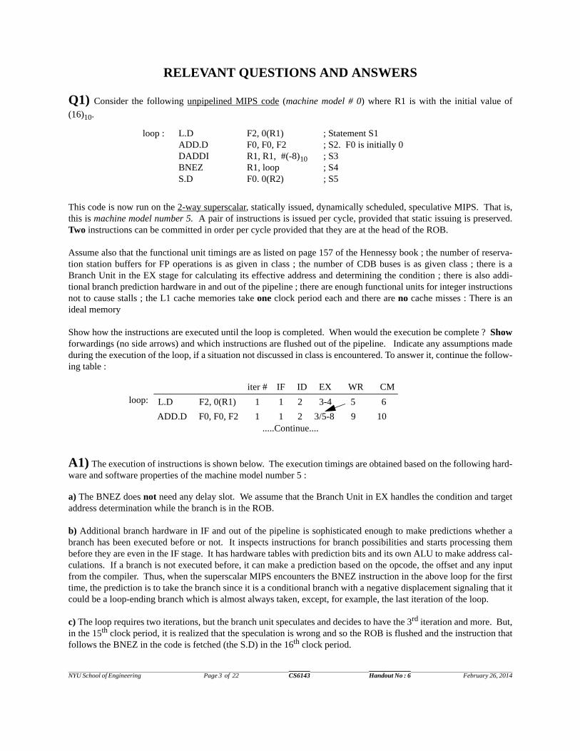
Q1) Consider the following unpipelined MIPS code (machine model # 0) where R1 is with the initial value of
(16)10.
This code is now run on the 2-way superscalar, statically issued, dynamically scheduled, speculative MIPS. That is,this is machine model number 5. A pair of instructions is issued per cycle, provided that static issuing is preserved.Two instructions can be committed in order per cycle provided that they are at the head of the ROB.
Assume also that the functional unit timings are as listed on page 157 of the Hennessy book ; the number of reserva-tion station buffers for FP operations is as given in class ; the number of CDB buses is as given class ; there is aBranch Unit in the EX stage for calculating its effective address and determining the condition ; there is also addi-tional branch prediction hardware in and out of the pipeline ; there are enough functional units for integer instructionsnot to cause stalls ; the L1 cache memories take one clock period each and there are no cache misses : There is anideal memory
Show how the instructions are executed until the loop is completed. When would the execution be complete ? Showforwardings (no side arrows) and which instructions are flushed out of the pipeline. Indicate any assumptions madeduring the execution of the loop, if a situation not discussed in class is encountered. To answer it, continue the follow-ing table :
A1) The execution of instructions is shown below. The execution timings are obtained based on the following hard-ware and software properties of the machine model number 5 :
a) The BNEZ does not need any delay slot. We assume that the Branch Unit in EX handles the condition and targetaddress determination while the branch is in the ROB.
b) Additional branch hardware in IF and out of the pipeline is sophisticated enough to make predictions whether abranch has been executed before or not. It inspects instructions for branch possibilities and starts processing thembefore they are even in the IF stage. It has hardware tables with prediction bits and its own ALU to make address cal-culations. If a branch is not executed before, it can make a prediction based on the opcode, the offset and any inputfrom the compiler. Thus, when the superscalar MIPS encounters the BNEZ instruction in the above loop for the firsttime, the prediction is to take the branch since it is a conditional branch with a negative displacement signaling that itcould be a loop-ending branch which is almost always taken, except, for example, the last iteration of the loop.
c) The loop requires two iterations, but the branch unit speculates and decides to have the 3rd iteration and more. But,in the 15th clock period, it is realized that the speculation is wrong and so the ROB is flushed and the instruction thatfollows the BNEZ in the code is fetched (the S.D) in the 16th clock period.
loop : L.D F2, 0(R1) ; Statement S1ADD.D F0, F0, F2 ; S2. F0 is initially 0DADDI R1, R1, #(-8)10 ; S3BNEZ R1, loop ; S4S.D F0. 0(R2) ; S5
iter # IF ID EX WR CM
L.D F2, 0(R1) 1 1 2 3-4 5 6
ADD.D F0, F0, F2 1 1 2 3/5-8 9 10.....Continue....
loop:

NYU School of Engineering Page 4 of 22 CS6143 Handout No : 6 February 26, 2014
Q2) Assume that the MIPS is implemented as the 2-way superscalar hardware-speculative Tomasulo algorithmmachine as discussed in class. That is, this is machine model number 5. A pair of instructions is issued per cycle,provided that static issuing is preserved. Two instructions can be committed in order per cycle provided that they areat the head of the ROB.
Assume also that the functional unit timings are as listed on page 157 of the Hennessy book ; the number of reserva-tion station buffers for FP operations is as given in class ; the number of CDB buses is as given class ; there is aBranch Unit in the EX stage for calculating its effective address and determining the condition ; there is also addi-
Instruction iter # IF ID EX WR CM
L.D F2, 0(R1) 1 1 2 3-4 5 6
ADD.D F0, F0, F2 1 1 2 3/5-8 9 10
DADDI R1, R1, #(-8)10 1 2 3 4 5 6/10
BNEZ R1, loop 1 2 3 5 6 7/11
L.D F2, 0(R1) 2 3 4 5-6 7 8/11
ADD.D F0, F0, F2 2 3 4 5/9-12 13 14
DADDI R1, R1, #(-8)10 2 4 5 6 7 8/14
BNEZ R1, loop 2 4 5 6/7 8 9/15
L.D F2, 0(R1) 3 5 6 7-8 9 10/15
ADD.D F0, F0, F2 3 5 6 7/13-15
DADDI R1, R1, #(-8)10 3 6 7 8 9 10/15
BNEZ R1, loop 3 6 7 8/9 10 11/15
L.D F2, 0(R1) 4 7 8 9-10 11 12/15
ADD.D F0, F0, F2 4 7 8 9/15
DADDI R1, R1, #(-8)10 4 8 9 10 11 12/15
BNEZ R1, loop 4 8 9 10/11 12 13/15
L.D F2, 0(R1) 5 9 10 11-12 13 14/15
ADD.D F0, F0, F2 5 9 10/12 13/15
DADDI R1, R1, #(-8)10 5 10 11/12 13 14 15
BNEZ R1, loop 5 10/12 13 14 15
L.D F2, 0(R1) 6 11/12 13 14 15
ADD.D F0, F0, F2 6 11/13 14/15
DADDI R1, R1, #(-8)10 6 13 14/15
BNEZ R1, loop 6 14/15
S.D F0, 0(R2) 16 17 18 19 20T
hes
e in
stru
ctio
ns
are
flu
shed
ou
t at
th
e en
dof
th
e 15
th c
lock
per
iod
Th
e ex
ecu
tion
com
ple
tes
in 2
0
loop:
loop:
loop:
loop:
loop:
loop:
ADD.D is stalledsince the3 RSsare busy
NYU School of Engineering Page 5 of 22 CS6143 Handout No : 6 February 26, 2014
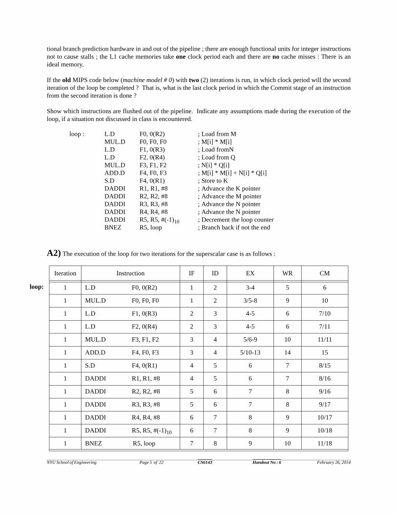
tional branch prediction hardware in and out of the pipeline ; there are enough functional units for integer instructionsnot to cause stalls ; the L1 cache memories take one clock period each and there are no cache misses : There is anideal memory.
If the old MIPS code below (machine model # 0) with two (2) iterations is run, in which clock period will the seconditeration of the loop be completed ? That is, what is the last clock period in which the Commit stage of an instructionfrom the second iteration is done ?
Show which instructions are flushed out of the pipeline. Indicate any assumptions made during the execution of theloop, if a situation not discussed in class is encountered.
A2) The execution of the loop for two iterations for the superscalar case is as follows :
Iteration Instruction IF ID EX WR CM
1 L.D F0, 0(R2) 1 2 3-4 5 6
1 MUL.D F0, F0, F0 1 2 3/5-8 9 10
1 L.D F1, 0(R3) 2 3 4-5 6 7/10
1 L.D F2, 0(R4) 2 3 4-5 6 7/11
1 MUL.D F3, F1, F2 3 4 5/6-9 10 11/11
1 ADD.D F4, F0, F3 3 4 5/10-13 14 15
1 S.D F4, 0(R1) 4 5 6 7 8/15
1 DADDI R1, R1, #8 4 5 6 7 8/16
1 DADDI R2, R2, #8 5 6 7 8 9/16
1 DADDI R3, R3, #8 5 6 7 8 9/17
1 DADDI R4, R4, #8 6 7 8 9 10/17
1 DADDI R5, R5, #(-1)10 6 7 8 9 10/18
1 BNEZ R5, loop 7 8 9 10 11/18
loop : L.D F0, 0(R2) ; Load from MMUL.D F0, F0, F0 ; M[i] * M[i]L.D F1, 0(R3) ; Load fromNL.D F2, 0(R4) ; Load from QMUL.D F3, F1, F2 ; N[i] * Q[i]ADD.D F4, F0, F3 ; M[i] * M[i] + N[i] * Q[i]S.D F4, 0(R1) ; Store to KDADDI R1, R1, #8 ; Advance the K pointerDADDI R2, R2, #8 ; Advance the M pointerDADDI R3, R3, #8 ; Advance the N pointerDADDI R4, R4, #8 ; Advance the N pointerDADDI R5, R5, #(-1)10 ; Decrement the loop counterBNEZ R5, loop ; Branch back if not the end
loop:
NYU School of Engineering Page 6 of 22 CS6143 Handout No : 6 February 26, 2014
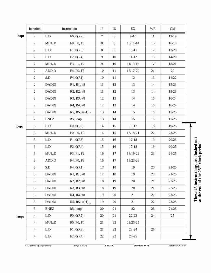
2 L.D F0, 0(R2) 7 8 9-10 11 12/19
2 MUL.D F0, F0, F0 8 9 10/11-14 15 16/19
2 L.D F1, 0(R3) 8 9 10-11 12 13/20
2 L.D F2, 0(R4) 9 10 11-12 13 14/20
2 MUL.D F3, F1, F2 9 10 11/13-16 17 18/21
2 ADD.D F4, F0, F3 10 11 12/17-20 21 22
2 S.D F4, 0(R1) 10 11 12 13 14/22
2 DADDI R1, R1, #8 11 12 13 14 15/23
2 DADDI R2, R2, #8 11 12 13 14 15/23
2 DADDI R3, R3, #8 12 13 14 15 16/24
2 DADDI R4, R4, #8 12 13 14 15 16/24
2 DADDI R5, R5, #(-1)10 13 14 15 16 17/25
2 BNEZ R5, loop 13 14 15 16 17/25
3 L.D F0, 0(R2) 14 15 16-17 18 19/25
3 MUL.D F0, F0, F0 14 15 16/18-21 22 23/25
3 L.D F1, 0(R3) 15 16 17-18 19 20/25
3 L.D F2, 0(R4) 15 16 17-18 19 20/25
3 MUL.D F3, F1, F2 16 17 18/19-22 23 24/25
3 ADD.D F4, F0, F3 16 17 18/23-26
3 S.D F4, 0(R1) 17 18 19 20 21/25
3 DADDI R1, R1, #8 17 18 19 20 21/25
3 DADDI R2, R2, #8 18 19 20 21 22/25
3 DADDI R3, R3, #8 18 19 20 21 22/25
3 DADDI R4, R4, #8 19 20 21 22 23/25
3 DADDI R5, R5, #(-1)10 19 20 21 22 23/25
3 BNEZ R5, loop 20 21 22 23 24/25
4 L.D F0, 0(R2) 20 21 22-23 24 25
4 MUL.D F0, F0, F0 21 22 23/25-25
4 L.D F1, 0(R3) 21 22 23-24 25
4 L.D F2, 0(R4) 22 23 24-25
Iteration Instruction IF ID EX WR CM
Th
ese
25 in
stru
ctio
ns
are
flu
shed
ou
t at
th
e en
d o
f th
e 25
th c
lock
per
iod
loop:
loop:
loop:
NYU School of Engineering Page 7 of 22 CS6143 Handout No : 6 February 26, 2014
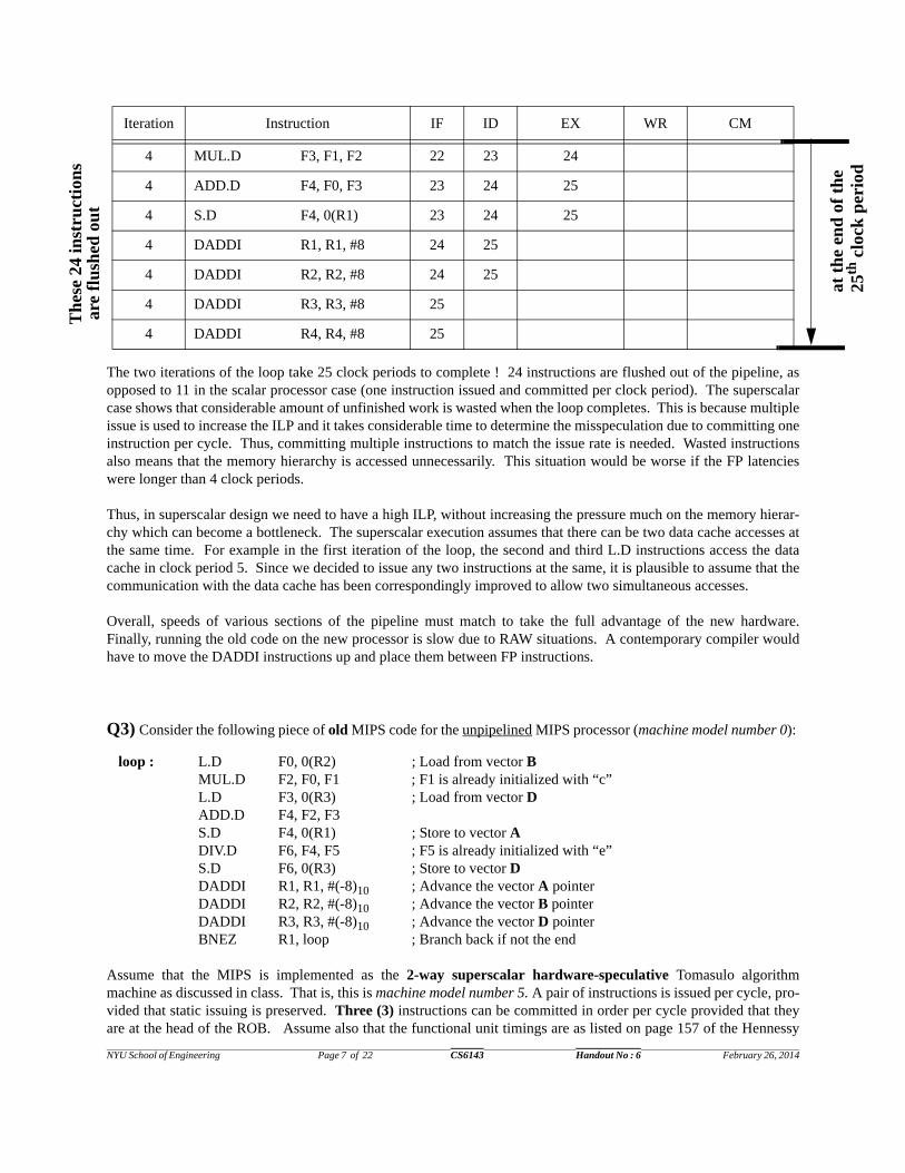
The two iterations of the loop take 25 clock periods to complete ! 24 instructions are flushed out of the pipeline, asopposed to 11 in the scalar processor case (one instruction issued and committed per clock period). The superscalarcase shows that considerable amount of unfinished work is wasted when the loop completes. This is because multipleissue is used to increase the ILP and it takes considerable time to determine the misspeculation due to committing oneinstruction per cycle. Thus, committing multiple instructions to match the issue rate is needed. Wasted instructionsalso means that the memory hierarchy is accessed unnecessarily. This situation would be worse if the FP latencieswere longer than 4 clock periods.
Thus, in superscalar design we need to have a high ILP, without increasing the pressure much on the memory hierar-chy which can become a bottleneck. The superscalar execution assumes that there can be two data cache accesses atthe same time. For example in the first iteration of the loop, the second and third L.D instructions access the datacache in clock period 5. Since we decided to issue any two instructions at the same, it is plausible to assume that thecommunication with the data cache has been correspondingly improved to allow two simultaneous accesses.
Overall, speeds of various sections of the pipeline must match to take the full advantage of the new hardware.Finally, running the old code on the new processor is slow due to RAW situations. A contemporary compiler wouldhave to move the DADDI instructions up and place them between FP instructions.
Q3) Consider the following piece of old MIPS code for the unpipelined MIPS processor (machine model number 0):
Assume that the MIPS is implemented as the 2-way superscalar hardware-speculative Tomasulo algorithmmachine as discussed in class. That is, this is machine model number 5. A pair of instructions is issued per cycle, pro-vided that static issuing is preserved. Three (3) instructions can be committed in order per cycle provided that theyare at the head of the ROB. Assume also that the functional unit timings are as listed on page 157 of the Hennessy
4 MUL.D F3, F1, F2 22 23 24
4 ADD.D F4, F0, F3 23 24 25
4 S.D F4, 0(R1) 23 24 25
4 DADDI R1, R1, #8 24 25
4 DADDI R2, R2, #8 24 25
4 DADDI R3, R3, #8 25
4 DADDI R4, R4, #8 25
Iteration Instruction IF ID EX WR CM
loop : L.D F0, 0(R2) ; Load from vector BMUL.D F2, F0, F1 ; F1 is already initialized with “c”L.D F3, 0(R3) ; Load from vector DADD.D F4, F2, F3S.D F4, 0(R1) ; Store to vector ADIV.D F6, F4, F5 ; F5 is already initialized with “e”S.D F6, 0(R3) ; Store to vector DDADDI R1, R1, #(-8)10 ; Advance the vector A pointerDADDI R2, R2, #(-8)10 ; Advance the vector B pointerDADDI R3, R3, #(-8)10 ; Advance the vector D pointerBNEZ R1, loop ; Branch back if not the end
Th
ese
24 in
stru
ctio
ns
at t
he
end
of
the
25th
clo
ck p
erio
d
are
flu
shed
ou
t

NYU School of Engineering Page 8 of 22 CS6143 Handout No : 6 February 26, 2014
book ; FP functional units are pipelined and the number of FP reservation station buffers is as given in class ; thenumber of CDB buses is as given class ; there is a Branch Unit in the EX stage for calculating its effective addressand determining the condition ; there is also additional branch prediction hardware in and out of the pipeline ; thereare enough functional units for integer instructions not to cause stalls ; the L1 cache memories take one clock periodeach and there are no cache misses : There is an ideal memory.
Assume that there are two iterations. In which clock period, will the second iteration of the loop be completed ? Thatis, what is the last clock period in which the Commit stage of an instruction from the second iteration be done last ?Also, show forwardings but not which instructions are flushed out of the pipeline.
A3)
The second iteration of the loop ends at clock period 24.
Iteration Instruction IF ID EX WR CM
1 L.D F0, 0(R2) 1 2 3-4 5 6
1 MUL.D F2, F0, F1 1 2 3/5-8 9 10
1 L.D F3, 0(R3) 2 3 4-5 6 7/10
1 ADD.D F4, F2, F3 2 3 4/9-12 13 14
1 S.D F4, 0(R1) 3 4 5 6 7/14
1 DIV.D F6, F4, F5 3 4 5/13-16 17 18
1 S.D F6, 0(R3) 4 5 6 7 8/18
1 DADDI R1, R1, #(-8)10 4 5 6 7 8/18
1 DADDI R2, R2, #(-8)10 5 6 7 8 9/19
1 DADDI R3, R3, #(-8)10 5 6 7 8 9/19
1 BNEZ R2, loop 6 7 8 9 10/19
2 L.D F0, 0(R2) 6 7 8-9 10 11/20
2 MUL.D F2, F0, F1 7 8 9/10-13 14 15/20
2 L.D F3, 0(R3) 7 8 9-10 11 12/20
2 ADD.D F4, F2, F3 8 9 10/14-17 18 19/21
2 S.D F4, 0(R1) 8 9 10 11 12/21
2 DIV.D F6, F4, F5 9 10 11/18-21 22 23
2 S.D F6, 0(R3) 9 10 11 12 13/23
2 DADDI R1, R1, #(-8)10 10 11 12 13 14/23
2 DADDI R2, R2, #(-8)10 10 11 12 13 14/24
2 DADDI R3, R3, #(-8)10 11 12 13 14 15/24
2 BNEZ R2, loop 11 12 13 14 15/24
loop :
loop :
NYU School of Engineering Page 9 of 22 CS6143 Handout No : 6 February 26, 2014
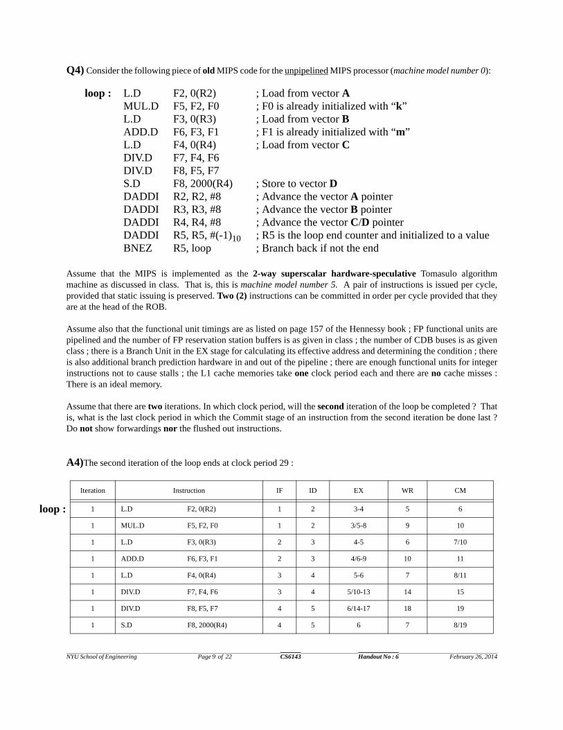
Q4) Consider the following piece of old MIPS code for the unpipelined MIPS processor (machine model number 0):
Assume that the MIPS is implemented as the 2-way superscalar hardware-speculative Tomasulo algorithmmachine as discussed in class. That is, this is machine model number 5. A pair of instructions is issued per cycle,provided that static issuing is preserved. Two (2) instructions can be committed in order per cycle provided that theyare at the head of the ROB.
Assume also that the functional unit timings are as listed on page 157 of the Hennessy book ; FP functional units arepipelined and the number of FP reservation station buffers is as given in class ; the number of CDB buses is as givenclass ; there is a Branch Unit in the EX stage for calculating its effective address and determining the condition ; thereis also additional branch prediction hardware in and out of the pipeline ; there are enough functional units for integerinstructions not to cause stalls ; the L1 cache memories take one clock period each and there are no cache misses :There is an ideal memory.
Assume that there are two iterations. In which clock period, will the second iteration of the loop be completed ? Thatis, what is the last clock period in which the Commit stage of an instruction from the second iteration be done last ?Do not show forwardings nor the flushed out instructions.
A4)The second iteration of the loop ends at clock period 29 :
Iteration Instruction IF ID EX WR CM
1 L.D F2, 0(R2) 1 2 3-4 5 6
1 MUL.D F5, F2, F0 1 2 3/5-8 9 10
1 L.D F3, 0(R3) 2 3 4-5 6 7/10
1 ADD.D F6, F3, F1 2 3 4/6-9 10 11
1 L.D F4, 0(R4) 3 4 5-6 7 8/11
1 DIV.D F7, F4, F6 3 4 5/10-13 14 15
1 DIV.D F8, F5, F7 4 5 6/14-17 18 19
1 S.D F8, 2000(R4) 4 5 6 7 8/19
loop : L.D F2, 0(R2) ; Load from vector AMUL.D F5, F2, F0 ; F0 is already initialized with “k”L.D F3, 0(R3) ; Load from vector BADD.D F6, F3, F1 ; F1 is already initialized with “m”L.D F4, 0(R4) ; Load from vector CDIV.D F7, F4, F6DIV.D F8, F5, F7S.D F8, 2000(R4) ; Store to vector DDADDI R2, R2, #8 ; Advance the vector A pointerDADDI R3, R3, #8 ; Advance the vector B pointerDADDI R4, R4, #8 ; Advance the vector C/D pointerDADDI R5, R5, #(-1)10 ; R5 is the loop end counter and initialized to a valueBNEZ R5, loop ; Branch back if not the end
loop :

NYU School of Engineering Page 10 of 22 CS6143 Handout No : 6 February 26, 2014
Q5) A 2-way superscalar MIPS with static issuing and hardware based speculative execution has been designed inclass. This is machine model number 5. You are asked to modify it to have dynamic issuing. Assume that the laten-cies are as mentioned on page 157 of the Hennessy book.
How does your design work ? Does dynamic issuing really help the superscalar MIPS ? Elaborate on this by show-ing cases where sequences of instructions clearly make use of the new issue policy of the MIPS. Be very specific. Isthe pressure on the compiler decreased or increased ?
A5) In dynamic issuing if an instruction is stalled in the instruction queue of the ID stage, the instruction(s) behind itcan be issued, bypassing the stalled instruction. For the statically issued superscalar MIPS, two instructions are ana-lyzed per clock period in the ID stage : I1 and I2. I1 is stalled if there is no entry in its reservation station and/or noslot in the ROB. I2 is stalled if there is no entry in its reservation station and/or no slot in the ROB. I2 is also stalledif I1 is stalled. We will keep the basic structure used for the superscalar MIPS for easier understanding of the discus-sion below. The new MIPS still issues two instructions from the instruction queue to the reservation stations and tothe reorder buffer per clock period, by keeping in mind that
i) we should be able to recover from wrong speculations, ii) keep precise interrupts and iii) detect all potential hazards between an instruction that is issued out-of-order and the instruction(s) it bypasses.
1 DADDI R2, R2, #8 5 6 7 8 9/20
1 DADDI R3, R3, #8 5 6 7 8 9/20
1 DADDI R4, R4, #8 6 7 8 9 10/21
1 DADDI R5, R5, #(-1)1 6 7 8 9 10/21
1 BNEZ R5, loop 7 8 9 10 11/22
2 L.D F2, 0(R2) 7 8 9-10 11 12/22
2 MUL.D F5, F2, F0 8 9 10/11-14 15 16/23
2 L.D F3, 0(R3) 8 9 10-11 12 13/23
2 ADD.D F6, F3, F1 9 10 11/12-15 16 17/24
2 L.D F4, 0(R4) 9 10 11-12 13 14/24
2 DIV.D F7, F4, F6 10 11 12/16-19 20 21/25
2 DIV.D F8, F5, F7 10 11 12/20-23 24 25
2 S.D F8, 2000(R4) 11 12 13 14 15/26
2 DADDI R2, R2, #8 11 12 13 14 15/26
2 DADDI R3, R3, #8 12 13 14 15 16/27
2 DADDI R4, R4, #8 12 13 14 15 16/27
2 DADDI R5, R5, #(-1)1 13 14 15 16 17/28
2 BNEZ R5, loop 13 14 15/16 17 18/29
Iteration Instruction IF ID EX WR CM
loop :

NYU School of Engineering Page 11 of 22 CS6143 Handout No : 6 February 26, 2014
There are four issues that we have to deal with in dynamic issuing : a) how do we pick instructions to bypass stalled instructions in the ID stage ? b) where do we keep bypassed instructions ? c) how do we keep track of bypassed instructions ? d) how do we ensure in-order completion ?
Issue (a) : If static issuing is used and the first instruction of the two instructions, I1, is stalled, I2 is also stalled. Indynamic issuing, I2 and I3 can be issued as long as there is no structural hazard associated with them :
Note that if say, I3 cannot be issued with I2, I4 can be issued or I5 or I6. Thus, the ID stage has to have a large “win-dow” of instructions to analyze per clock period, making the ID stage very complex. For the rest of the discussion ofthis problem, assume that I1 cannot be issued, but I2 and I3 can be issued.
Issue (b) : One solution is that we move stalled instructions out of the ID stage (out of the instruction queue) and tothe ROB, but treat them as unissued !!! Since I2 and I3 are issued we move them to both the reorder buffer and theirreservation stations. We need more connections from ID to reservation stations and the ROB. Also, keeping stalledinstructions in the reorder buffer requires that the reorder buffer be larger now to allow more instructions :
Issue (c) : To “remember” that there are unissued instructions in the ROB a linked list in hardware can be used. Whathappens if there are a number of unissued instructions in the ROB “that can be “issued” in addition to the “issuable”instructions in the instruction queue ? We have to give priority to the unissued instructions in the ROB and so we tryto move (issue) two instructions from the ROB to the reservation stations. If we cannot, we try to move one instruc-tion from the instruction queue and one from the ROB to the reservation stations. In another scenario, two instruc-tions are issued from the instruction queue. When we move an instruction from the ROB to a reservation station, we“delink” it from the linked list and treat it as issued. The ROB this way satisfies correct speculative execution andprecise interrupts. But, the CM stage is much more complex now : we must be able to write from the ROB to the res-ervation stations after checking that there is no resource dependency, i.e. there is a free reservation station.
Issue (d) : In-order completion is ensured by retiring only those instructions that are at the head of the ROB which arein the order they were stored. Recovery from wrong speculations is done when an incorrectly speculated branchreaches the head of the queue. The instructions behind the branch are flushed out of the ROB. It is possible thatsome of the flushed instructions are unissued instructions.... Handling precise interrupts is as before : when aninstruction reaches the head of the queue its exception is handled. Our solution implies that the CPU will issue twoinstructions every clock period as long as the ROB is not full. It is guaranteed ! One would try to keep the ROB notfilled up, by trying to commit more than two instructions per clock period.
......
Ready tobe issued Has to be stalled, that is cannot be issuedI1
I2I3 These two instructions can be issued.
instruction queueTheIDStage
......
I1I2I3
......
I1
I2I3
hardwarepointer forunissuedinstructions
to thereorderbuffer
to the reservationstations
the instructionqueue in
....
....
nullthe IDstage
Reorder Buffer

NYU School of Engineering Page 12 of 22 CS6143 Handout No : 6 February 26, 2014
Dynamic issuing helps if there are back-to-back long-latency instructions with true dependencies among them. Instatic issuing, after dependent instructions are issued to their reservation stations, they wait there a long time for longlatency instructions. This quickly results in full reservation stations. Structural hazards gradually develop, forcinginstructions in the ID stage to stall. Independent instructions behind the stalled instructions in the ID stage stall. Notethat this situation can happen if the CPU is running an old code. With dynamic issuing, the pressure on the compileris reduced since the hardware looks for independent instructions and arbitrarily searches ahead as long as there isspace in the reorder buffer. The compiler does not have to do a complete global analysis of the program for best pos-sible sequence of independent instructions. The compiler can be old.
Note also that there is research on out-of-order commit : Mateo Valero and his colleagues published a paper at theHigh Performance Computer Architecture (HPCA) conference in 2004 : “Out-of-Order Commit Processors.”
Q6) Write the MIPS code for a machine model number 2 assuming latencies given on page 157 of the Hennessybook for the following piece of high-level code :
k = 0.0 for (i = 1 ; i<= 64 ; i++)
k = k + A[i] * B[i]
Then, assuming that the MIPS is a VLIW machine as described in class. That is, this is machine model number 6.Show how the instructions are issued for each clock period. Your code will be again based on the latencies as speci-fied on page 157 of the Hennessy book.
A6) This code implements the dot product. The scalar code for this piece of high-level language code is as follows :
L.D F0, #0loop : L.D F2, 0(R8) ; R8 points at the end of vector A
L.D F4, 0(R9) ; R9 points at the end of vector BDADDI R9, R9, #(-8)10 MUL.D F6, F2, F4NOPDADDI R8, R8, #(-8)10 BNEZ R8, loopADD.D F0, F0, F6NOPNOPS.D F0, 0(R10 ; R10 points at scalar “k”
We unroll the loop eight times in order to have as many operations as possible during the VLIW execution. After theloop is exited we have to do more computations : four more instructions (three adds and a store) as shown on the nextpage. Though, it seems there are a lot of NOPs after we exit the loop, it is not the case : instructions out of the loopare placed around these four instructions.
Note also the importance of having many registers in the architecture for effective VLIW execution. In this case,having many FP registers helps unroll the loop eight times :

NYU School of Engineering Page 13 of 22 CS6143 Handout No : 6 February 26, 2014
Q7) Consider the old original MIPS code in Past Exam Question 4 again.
Assume that the MIPS is implemented as the VLIW MIPS processor : That is, this is machine model number 6.Assume that the functional unit timings are as listed in Figure 2.2 on page 157 of the Hennessy book.
Mem 1 Mem 2 FP 1 FP 2 Int/Br
L.D F0, #0 L.D F2, #0
L.D F4, #0 L.D F6, #0
L.D F8, 0(R8) L.D F10, 0(R9)
L.D F12, (-8)10(R8) L.D F14, (-8)10(R9)
L.D F16, (-16)10(R8) L.D F18, (-16)10(R9) MUL.D F8, F8,F10
L.D F20, (-24)10(R8) L.D F22, (-24)10(R9) MUL.D F12, F12, F14
L.D F24, (-32)10(R8) L.D F26, (-32)10(R9) MUL.D F16, F16, F18
L.D F28, (-40)10(R8) L.D F30, (-40)10(R9) MUL.D F20, F20, F22
L.D F8, (-48)10(R8) L.D F10, (-48)10(R9) MUL.D F24, F24, F26 ADD.D F0, F0, F8
L.D F12, (-54)10(R8) L.D F14, (-54)10(R9) MUL.D F28, F28, F30 ADD.D F2, F2, F12
MUL.D F8, F8, F10 ADD.D F4, F4, F16
MUL.D F12, F12, F14 ADD.D F6, F6, F20
ADD.D F0, F0, F24
ADD.D F2, F2, F28 DADDI R8, R8, #(-64)10
ADD.D F4, F4, F8 BNEZ R8, Loop
ADD.D F6, F6, F12 DADDI R9, R9, #(-64)10
ADD.D F0, F0, F2
ADD.D F4, F4, F6
ADD.D F0, F0, F4
S.D F0, 0(R10)
loop
end ofthe loop B
ran
ch
del
ay s
lot
NYU School of Engineering Page 14 of 22 CS6143 Handout No : 6 February 26, 2014
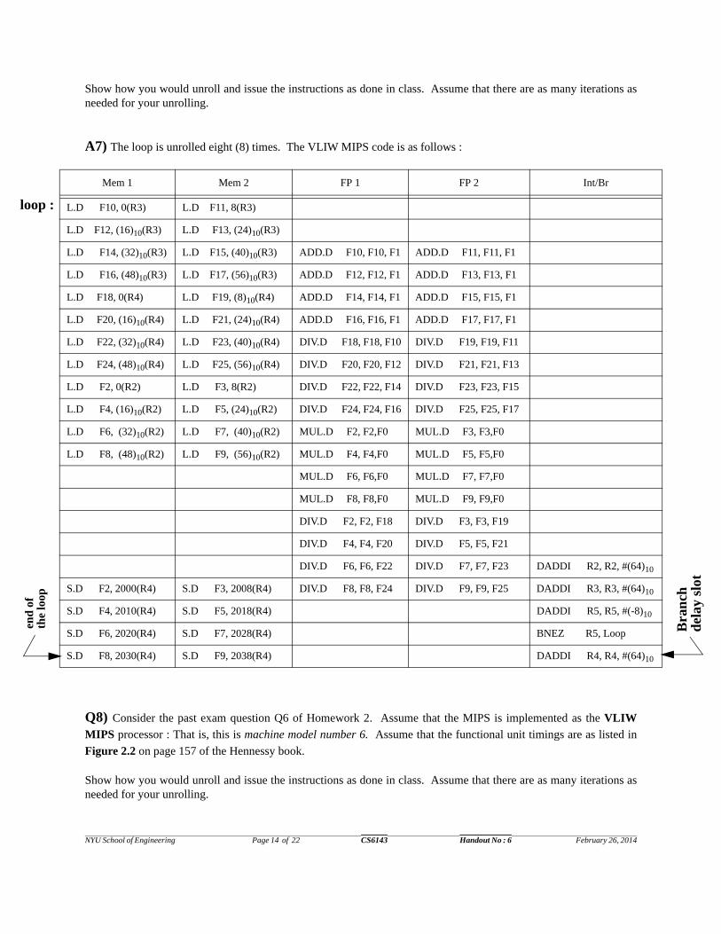
Show how you would unroll and issue the instructions as done in class. Assume that there are as many iterations asneeded for your unrolling.
A7) The loop is unrolled eight (8) times. The VLIW MIPS code is as follows :
Q8) Consider the past exam question Q6 of Homework 2. Assume that the MIPS is implemented as the VLIW
MIPS processor : That is, this is machine model number 6. Assume that the functional unit timings are as listed in
Figure 2.2 on page 157 of the Hennessy book.
Show how you would unroll and issue the instructions as done in class. Assume that there are as many iterations asneeded for your unrolling.
Mem 1 Mem 2 FP 1 FP 2 Int/Br
L.D F10, 0(R3) L.D F11, 8(R3)
L.D F12, (16)10(R3) L.D F13, (24)10(R3)
L.D F14, (32)10(R3) L.D F15, (40)10(R3) ADD.D F10, F10, F1 ADD.D F11, F11, F1
L.D F16, (48)10(R3) L.D F17, (56)10(R3) ADD.D F12, F12, F1 ADD.D F13, F13, F1
L.D F18, 0(R4) L.D F19, (8)10(R4) ADD.D F14, F14, F1 ADD.D F15, F15, F1
L.D F20, (16)10(R4) L.D F21, (24)10(R4) ADD.D F16, F16, F1 ADD.D F17, F17, F1
L.D F22, (32)10(R4) L.D F23, (40)10(R4) DIV.D F18, F18, F10 DIV.D F19, F19, F11
L.D F24, (48)10(R4) L.D F25, (56)10(R4) DIV.D F20, F20, F12 DIV.D F21, F21, F13
L.D F2, 0(R2) L.D F3, 8(R2) DIV.D F22, F22, F14 DIV.D F23, F23, F15
L.D F4, (16)10(R2) L.D F5, (24)10(R2) DIV.D F24, F24, F16 DIV.D F25, F25, F17
L.D F6, (32)10(R2) L.D F7, (40)10(R2) MUL.D F2, F2,F0 MUL.D F3, F3,F0
L.D F8, (48)10(R2) L.D F9, (56)10(R2) MUL.D F4, F4,F0 MUL.D F5, F5,F0
MUL.D F6, F6,F0 MUL.D F7, F7,F0
MUL.D F8, F8,F0 MUL.D F9, F9,F0
DIV.D F2, F2, F18 DIV.D F3, F3, F19
DIV.D F4, F4, F20 DIV.D F5, F5, F21
DIV.D F6, F6, F22 DIV.D F7, F7, F23 DADDI R2, R2, #(64)10
S.D F2, 2000(R4) S.D F3, 2008(R4) DIV.D F8, F8, F24 DIV.D F9, F9, F25 DADDI R3, R3, #(64)10
S.D F4, 2010(R4) S.D F5, 2018(R4) DADDI R5, R5, #(-8)10
S.D F6, 2020(R4) S.D F7, 2028(R4) BNEZ R5, Loop
S.D F8, 2030(R4) S.D F9, 2038(R4) DADDI R4, R4, #(64)10
loop :
end
of
the
loop
Bra
nch
d
elay
slo
t

NYU School of Engineering Page 15 of 22 CS6143 Handout No : 6 February 26, 2014
A8) The VLIW MIPS code is below. The loop is unrolled eight (8) times :
Q9) Consider the piece of old MIPS code for the unpipelined MIPS processor (machine model number 0) below :
Mem 1 Mem 2 FP 1 FP 2 Int/Br
L.D F1, 0(R1) L.D F0, 8(R1)
L.D F6, (16)10(R1) L.D F7, (24)10(R1)
L.D F8, (32)10(R1) L.D F9, (40)10(R1) ADD.D F12, F2, F1 ADD.D F13, F2, F0
L.D F10, (48)10(R1) L.D F11, (56)10(R1) ADD.D F14, F2, F6 ADD.D F15, F2, F7
L.D F4, 0(R4) L.D F20, 8(R4) ADD.D F16, F2, F8 ADD.D F17, F2, F9
L.D F21, (16)10(R4) L.D F22, (24)10(R4) ADD.D F18, F2, F10 ADD.D F19, F2, F11
L.D F23, (32)10(R4) L.D F24, (40)10(R4) SUB.D F12, F4, F12 SUB.D F13, F20, F13
L.D F25, (48)10(R4) L.D F26, (56)10(R4) SUB.D F14, F21, F14 SUB.D F15, F22, F15
S.D F12, 0(R1) S.D F13, 8(R1) SUB.D F16, F23, F16 SUB.D F17, F24, F17
S.D F14, (16)10(R1) S.D F15, (24)10(R1) SUB.D F18, F25, F18 SUB.D F19, F26, F19
S.D F16, (32)10(R1) S.D F17, (40)10(R1) MUL.D F1, F12, F1 MUL.D F0, F13, F0
S.D F18, (48)10(R1) S.D F19, (56)10(R1) MUL.D F6, F14, F6 MUL.D F7, F15, F7
MUL.D F8, F16, F8 MUL.D F9, F17, F9 DADDI R1, R1, #(64)10
S.D F1, 0(R5) S.D F0, 8(R5) MUL.D F10, F18, F9 MUL.D F11, F19, F11 DADDI R4, R4, #(64)10
S.D F6, (16)10(R5) S.D F7, (24)10(R5) DADDI R6, R6, #(-8)10
S.D F8, (32)10(R5) S.D F9, (40)10(R5) BNEZ R6, loop
S.D F10, (48)10(R5) S.D F11, (56)10(R5) DADDI R5, R5, #(64)10
loop : L.D F0, 0(R1) ; Load from vector AMUL.D F0, F0, F1 ; F1 is already initialized with constant “k”S.D F0, 0(R1)L.D F2, 0(R2) ; Load from vector BDIV.D F2, F2, F3 ; F3 is already initialized with constant “p”L.D F4, 0(R3) ; Load from vector CADD.D F2, F2, F4ADD.D F2, F2, F0S.D F2, 0(R2)DADDI R1, R1, #(-8)10DADDI R2, R2, #(-8)10DADDI R3, R3, #(-8)10DADDI R4, R4, #(-1)10BNEZ R4, loop
loop :
end
of
the
loop
Bra
nch
d
elay
slo
t

NYU School of Engineering Page 16 of 22 CS6143 Handout No : 6 February 26, 2014
Assume that the MIPS is implemented as the VLIW MIPS processor : That is, this is machine model number 6.Assume that the functional unit timings are as follows : ADD.D takes 3 clock periods in the EX stage, MUL.D takes5 clock periods in the EX stage and DIV.D takes 7 clock periods in the EX stage
Show how you would unroll and issue the instructions as done in class. Assume that there are as many iterations asneeded for your unrolling.
A9) The VLIW MIPS code is as follows :
The loop is unrolled eight (8) times. Unrolling 8 times is necessary since the DIV.D instruction takes 7 clock periodsin EX. Since the DIV.D instructions are independent of the MUL.D instructions, we start them early to reduce thenumber of clock periods further.
Mem 1 Mem 2 FP 1 FP 2 Int/Br
L.D F2, 0(R2) L.D F5, (-8)10(R2)
L.D F6, (-16)10(R2) L.D F7, (-24)10(R2)
L.D F8, (-32)10(R2) L.D F9, (-40)10(R2) DIV.D F2, F2, F3 DIV.D F5, F5, F3
L.D F10, (-48)10(R2) L.D F11, (-56)10(R2) DIV.D F6, F6, F3 DIV.D F7, F7, F3
L.D F0, 0(R1) L.D F12, (-8)10(R1) DIV.D F8, F8, F3 DIV.D F9, F9, F3
L.D F13, (-16)10(R1) L.D F14, (-24)10(R1) DIV.D F10, F10, F3 DIV.D F11, F11, F3
L.D F15, (-32)10(R1) L.D F16, (-40)10(R1) MUL.D F0, F0, F1 MUL.D F12, F12, F1
L.D F17, (-48)10(R1) L.D F18, (-56)10(R1) MUL.D F13, F13, F1 MUL.D F14, F14, F1
L.D F4, 0(R3) L.D F19, (-8)10(R3) MUL.D F15, F15, F1 MUL.D F16, F16, F1
L.D F20, (-16)10(R3) L.D F21, (-24)10(R3) MUL.D F17, F17, F1 MUL.D F18, F18, F1
L.D F22, (-32)10(R3) L.D F23, (-40)10(R3) ADD.D F2, F2, F4 ADD.D F5, F5, F19
L.D F24, (-48)10(R3) L.D F25, (-56)10(R3) ADD.D F6, F6, F20 ADD.D F7, F7, F21
S.D F0, 0(R1) S.D F12, (-8)10(R1) ADD.D F8, F8, F22 ADD.D F9, F9, F23
S.D F13, (-16)10(R1) S.D F14, (-24)10(R1) ADD.D F10, F10, F24 ADD.D F11, F11, F25
S.D F15, (-32)10(R1) S.D F16, (-40)10(R1) ADD.D F2, F2, F0 ADD.D F5, F5, F12
S.D F17, (-48)10(R1) S.D F18, (-56)10(R1) ADD.D F6, F6, F13 ADD.D F7, F7, F14 DADDI R1, R1, #(-64)10
S.D F2, 0(R2) S.D F5, (-8)10(R2) ADD.D F8, F8, F15 ADD.D F9, F9, F16 DADDI R3, R3, #(-64)10
S.D F6, (-16)10(R2) S.D F7, (-24)10(R2) ADD.D F10, F10, F17 ADD.D F11, F11, F18 DADDI R4, R4, #(-8)10
S.D F8, (-32)10(R2) S.D F9, (-40)10(R2) BNEZ R4, loop
S.D F10, (-48)10(R2) S.D F11, (-56)10(R2) DADDI R2, R2, #(-64)10
Bra
nch
del
ay s
lot
loop :

NYU School of Engineering Page 17 of 22 CS6143 Handout No : 6 February 26, 2014
Q10) Consider the following VMIPS code :
L.D F0, R1 ; R1 points at variable “a”LV V1, R2 ; R2 points at array XMULVS .D V2, V1, F0LV V3, R3 ; R3 points at array YADDV.D V4, V2, V3SV R3, V4
a) Write down the corresponding algorithm in the style used in class. Assume that the VLR and VM registers are ini-tialized to allow 64-element vector operations. What is the time complexity of the algorithm ?
b) Determine how many clock periods it would take to run the above VMIPS vector code. This is machine modelnumber 7. Assume that the hardware allows chaining but there is only one memory pipeline. Indicate any assump-tions made during the execution of the loop, if a situation not discussed in class is encountered.
A10) a)
There is a single loop with one statement. The loop iterates n times, the length of the vectors. The time complexity isthen linear : O(n).
b) We observe that due to one memory pipeline there are three convoys. Then the execution time is :
Q11) Consider the old original MIPS code in Past Exam Question 4 again. Assume that the MIPS is implemented
as the VMIPS processor : That is, this is machine model number 7.
a) Rewrite the old code in terms of VMIPS instructions. Add comments to your code. Assume that the loop has 64iterations. Also assume that the VM, VLR, R2, R3, R4, F0 and F1 registers have been already appropriately initial-ized. Finally, assume that R6 is initialized to (R4 + 2000).
b) Show the execution timings as discussed in class. Assume that there is chaining. Also assume that there are two(2) memory pipelines.
A11) a) The VMIPS code is as follows :
for (i = 1 ; i <= 64 ; i++) Y[i] = (a * X]i]) + Y[i] O(n)
12
12 63
7 63
12 63
6 63
12 63
L.D
LV
MULVS.D
LV
ADDV.D
SV
Convoy 1
Convoy 2
Convoy 3
The approximate execution time = 237 clock periods
NYU School of Engineering Page 18 of 22 CS6143 Handout No : 6 February 26, 2014
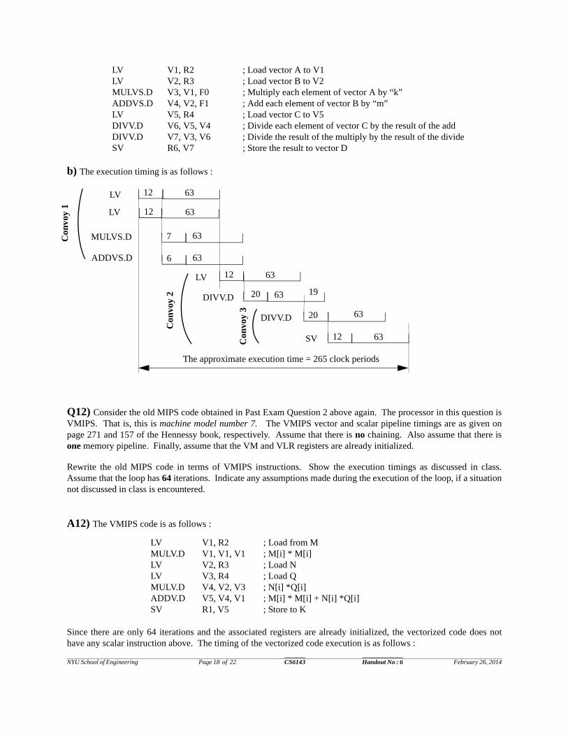
LV V1, R2 ; Load vector A to V1LV V2, R3 ; Load vector B to V2MULVS.D V3, V1, F0 ; Multiply each element of vector A by “k”ADDVS.D V4, V2, F1 ; Add each element of vector B by “m”LV V5, R4 ; Load vector C to V5DIVV.D V6, V5, V4 ; Divide each element of vector C by the result of the addDIVV.D V7, V3, V6 ; Divide the result of the multiply by the result of the divideSV R6, V7 ; Store the result to vector D
b) The execution timing is as follows :
Q12) Consider the old MIPS code obtained in Past Exam Question 2 above again. The processor in this question isVMIPS. That is, this is machine model number 7. The VMIPS vector and scalar pipeline timings are as given onpage 271 and 157 of the Hennessy book, respectively. Assume that there is no chaining. Also assume that there isone memory pipeline. Finally, assume that the VM and VLR registers are already initialized.
Rewrite the old MIPS code in terms of VMIPS instructions. Show the execution timings as discussed in class.Assume that the loop has 64 iterations. Indicate any assumptions made during the execution of the loop, if a situationnot discussed in class is encountered.
A12) The VMIPS code is as follows :
Since there are only 64 iterations and the associated registers are already initialized, the vectorized code does nothave any scalar instruction above. The timing of the vectorized code execution is as follows :
12LV
MULVS.D
DIVV.D
Con
voy
1
63
LV
Con
voy
2
The approximate execution time = 265 clock periods
12 63
7 63
DIVV.D 63
20 63
SV 12 63
ADDVS.D 6 63
12LV 63
20 19
Con
voy
3
LV V1, R2 ; Load from MMULV.D V1, V1, V1 ; M[i] * M[i]LV V2, R3 ; Load NLV V3, R4 ; Load QMULV.D V4, V2, V3 ; N[i] *Q[i]ADDV.D V5, V4, V1 ; M[i] * M[i] + N[i] *Q[i]SV R1, V5 ; Store to K
NYU School of Engineering Page 19 of 22 CS6143 Handout No : 6 February 26, 2014
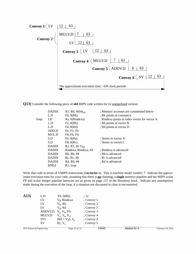
Q13) Consider the following piece of old MIPS code written for its unpipelined version :
Write that code in terms of VMIPS instructions (vectorize it). This is machine model number 7. Indicate the approx-imate execution time for your code, assuming that there is no chaining, a single memory pipeline and the MIPS scalarFP and scalar integer pipeline latencies are as given on page 157 of the Hennessy book. Indicate any assumptionsmade during the execution of the loop, if a situation not discussed in class is encountered.
A13) L.D F0, 0(Rk) ; 12LV VP, Rindexa ; Convoy 1LV Vb, Rb ; Convoy 2LV Vd, Rd ; Convoy 3ADDVS.D Va, Vb, F0 ; Convoy 3MULV.D Vc, Va, Vd ; Convoy 4SVI (R0 + VP), Va ; Convoy 4SV Rc, Vc ; Convoy 5
12
7 63
12 63
12 63
7 63
LV
MULV.D
LV
LV
MULV.D
Convoy 1
12 63SV
63
The approximate execution time : 439 clock periods
6 63ADDV.D
Convoy 2
Convoy 3
Convoy 4
Convoy 5
Convoy 6
DADDI R1, R0, #(64)10 ; Memory accesses are commented below :L.D F0, 0(Rk) ; Rk points at constant k
loop: LD Ra, 0(Rindexa) ; Rindexa points at index vector for vector AL.D F2, 0(Rb) ; Rb points at vector BL.D F4, 0(Rd) ; Rd points at vector DADD.D F6, F2, F0MUL.D F8, F6, F4S.D F6, 0(Ra) ; Stores to vector AS.D F8, 0(Rc) ; Stores to vector CDADDI R1, R1, #(-1)10 DADDI Rindexa, Rindexa, #4 ; Rindexa is advancedDADDI Rb, Rb, #8 ; Rb is advancedDADDI Rc, Rc, #8 ; Rc is advancedDADDI Rd, Rd, #8 ; Rd is advancedBNEZ R1, loop

NYU School of Engineering Page 20 of 22 CS6143 Handout No : 6 February 26, 2014
Q14) Consider the past exam question Q6 of Homework 2. Assume that the MIPS is implemented as the VMIPS
processor : That is, this is machine model number 7.
Rewrite the old code in terms of VMIPS instructions. Add comments to your code. Assume that the loop has 64 iter-ations. Also assume that the VM, VLR, R1, R4, R5 and F2 registers have been already appropriately initialized.Then, show the execution timings as discussed in class. Assume that there is chaining. Also assume that there arethree (3) memory pipelines.
A14) The VMIPS code and the execution timing are as follows :
LV V1, R1 ; Load vector A to V1LV V4, R4 ; Load vector B to V2ADDVS.D V3, V1, F2 ; Add “k” to each element of vector A SV R1, V3 ; Store the result back to vector ASUBV.D V6, V4, V3 ; Subtract the new value of each element of A from each element of BMULV.D V5, V6, V1 ; Multiply each subtraction result by an old element of ASV R5, V5 ; Store the multiplication result to vector C
12
12 63
7 63
6 63
12 63
LD
LV
MULV.D
ADDVS
SVI
Convoy 1
Convoy 5
Convoy 4
LVConvoy 2 12 63
LVConvoy 3
12 63
12 63SVThe approximate execution time = 387 clock periods
12LV V1, R1
ADDVS.D V3, V1, F2
Con
voy
1
63
LV V4, R4
Convoy 2The approximate execution
12 63
6 63
63
SV R5, V5 12 63
6 63
7
SUBV.D V6, V4, V3
MULV.D V5, V6, V1
time : 150 clock periods
SV R1, V3 12 63
NYU School of Engineering Page 21 of 22 CS6143 Handout No : 6 February 26, 2014
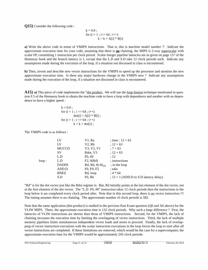
Q15) Consider the following code : k = 0.0 ;for (i = 1 ; i<= 64 ; i++)
k = k + A[i] * B[i]
a) Write the above code in terms of VMIPS instructions. That is, this is machine model number 7. Indicate theapproximate execution time for your code, assuming that there is no chaining, the MIPS is 2-way superscalar withscalar FP, committing 1 instruction per clock period. Scalar integer pipeline latencies are as given on page 157 of theHennessy book and the branch latency is 1, except that the L.D and S.D take 12 clock periods each. Indicate anyassumptions made during the execution of the loop, if a situation not discussed in class is encountered.
b) Then, invent and describe new vector instructions for the VMIPS to speed up the processor and mention the newapproximate execution time. Is there any major hardware change in the VMIPS now ? Indicate any assumptionsmade during the execution of the loop, if a situation not discussed in class is encountered.
A15) a) This piece of code implements the “dot product. We will use the loop fission technique mentioned in ques-tion F.5 of the Hennessy book to obtain the machine code to have a loop with dependence and another with no depen-dence to have a higher speed :
k = 0.0 ;for (i = 1 ; i <= 64 ; i++)
dot[i] = A[i] * B[i] ;for (i = 1 ; i <= 64 ; i++)
k = k + dot[i] ;
The VMIPS code is as follows :
LV V1, Ra ; time : 12 + 63LV V2, Rb ; 12 + 63MULV.D V3, V2, V1 ; 7 + 63SV Rdot, V3 ; 12 + 63L.D F0, #0 ; 12
loop : L.D F2, 0(Rd) ; instructionsDADDI Rd, Rd, #(-8)10 ; in the loopADD.D F0, F0, F2 ; take BNEZ Rd, loop ; 4 * 64S.D F0, Rk ; 12 + 1 (ADD.D to S.D latency delay)
“Rd” is for the dot vector just like the Rdot register is. But, Rd initially points at the last element of the dot vector, notat the first element of the dot vector. The “L.D F0, #0” instruction takes 12 clock periods then the instructions in theloop below it are completed every clock period after. Note that in this second loop, there is no vector instruction !!!The timing assumes there is no chaining. The approximate number of clock periods is 582.
Note that the same application (dot-product) is studied in the previous Past Exam question (Q6 and A6 above) for theVLIW MIPS. There, the approximate execution time is 132 clock periods. Why such a large difference ? First, thelatencies of VLIW instructions are shorter than those of VMIPS instructions. Second, for the VMIPS, the lack ofchaining increases the execution time by limiting the overlapping of vector instructions. Third, the lack of multiplememory pipelines limits simultaneous independent vector loads and stores to proceed. Finally, the lack of overlap-ping of vector instruction executions with the scalar instruction executions in the loop forces the loop to start after allvector instructions are completed. If these limitations are removed, which would be the case for a supercomputer, theapproximate execution time for the VMIPS would be approximately 245 clock periods.

NYU School of Engineering Page 22 of 22 CS6143 Handout No : 6 February 26, 2014
Still the time is not better than the VLIW case !! However, the VLIW case suffers from two problems not observed inthe VMIPS case and can make the VLIW slower : the VLIW code is large with 3240 bits (which also includesinstructions not related to the dot product operation). The VMIPS code is 384 bits. The second and more importantproblem is that the memory interface unit of VLIW machines is not as sophisticated as that of vector machines. Thus,there will be a lot of idle clock periods for fetching so many VLIW instruction bits and also performing two paralleldata accesses per clock period. The VLIW execution time would be worse than 132 clock periods...
b) The dot-product is a “reduction” operation where two vectors (A and B) are reduced to a scalar number “k.” So,we devise a new VMIPS vector instruction called DPV (Dot Product of Vectors) :
DPV F0, V1, V2 ; F0 <--- V1 * V2
Assume that the latency for the DPV is 10 clock periods, since after the multiplication an addition is needed. Then thedot product program becomes :
The hardware is changed such that the vector FP multiplier unit is chained to the scalar FP add unit (which stores in ascalar FP register). The chaining requires a new bus, a Vector-Scalar, VS bus, from the vector multiplier to the scalarFP Add functional unit. In the context of speculative superscalar MIPS execution, this means a reservation stationentry for the DPV in the integer section. That reservation station waits for the 64 results coming on the VS bus fromthe vector unit. The VS bus is parallel to the integer and FP CDB bus(es). If full chaining and multiple memorypipes are employed, the execution time would be 109 clock periods.
Q16) Superscalar processors have closed the speed gap they had with vector processors considerably when they runvector-oriented applications with loop-level parallelism. One main advantage of vector processors that still remains,is their handling of pipelined non-unit stride and sparse matrix memory accesses. Suggest hardware and softwaretechniques that can help superscalar processor close this gap too. You may invent your own reasonable solutions.
A16) A number of software techniques can be tried on the scalar code so that i) the access pattern of the code is changed from rows/columns to blocks (blocking). That is, the code accesses ablock containing a portion of a number of rows and columns. In order to do that arrays are stored blockwise, not row-major nor column-major (see Blocking on page 90 of the Hennessy book). ii) back-to-back nonsequential memoryaccesses are converted to sequential memory accesses : loop interchange (see Loop Interchange on page 88 of theHennessy book). iii) data brought into the cache is used again and again without misses then removed from thecache: loop fusion (not loop fission). iv) The compiler unrolls loops to access elements in advance. Also, for non-loop situations, the compiler rearranges the code so that memory reference instructions are moved up and down.
A number of hardware+software techniques can be used :i) Special buffers between the memory and the cache can prefetch data automatically. If there are special dataprefetch instructions for caches, the compiler inserts them appropriately. ii) The data cache can deliver in a pipelinedfashion where the first memory request to a cache block is checked for TLB and cache hits, taking more than oneclock period. After that, in every clock period an element from the same block is delivered : TLB translation andcache hit checking are done only once, for example, 64 data elements. Note that this is an active research area now.iii) Second and third level cache memories can perform similarly. iv) There can be indexed memory access instruc-tions for cache memories
LV V1, Ra ; time : 12 + 63LV V2, Rb ; 12 + 63DPV F0, V1, V2 ; 10 + 63S.D F0, Rk ; 12
The approximate timeis 235 clock periods.
The speedup is 2.18