Embed Size (px)
Citation preview
CS 61:Database Systems
ER models
Adapted from Silberschatz, Korth, and Sundarshan unless otherwise noted
2
Agenda
1. Entity Relationship (ER) models
2. Relationships
3. How to build an ER model
4. Reverse and forward engineering
3
ER models use three basic concepts: Entities, Relationships, and Attributes
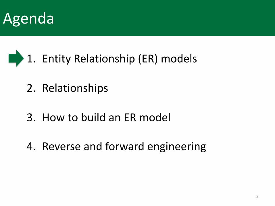
ER model (ERM) rests on three basic concepts: 1. Entities: what are the nouns involved?2. Relationships: how are the entities related3. Attributes: what characteristics do entities have?
Entity Relationship (ER) models
ER diagram (ERD)expresses the overall model graphically
4
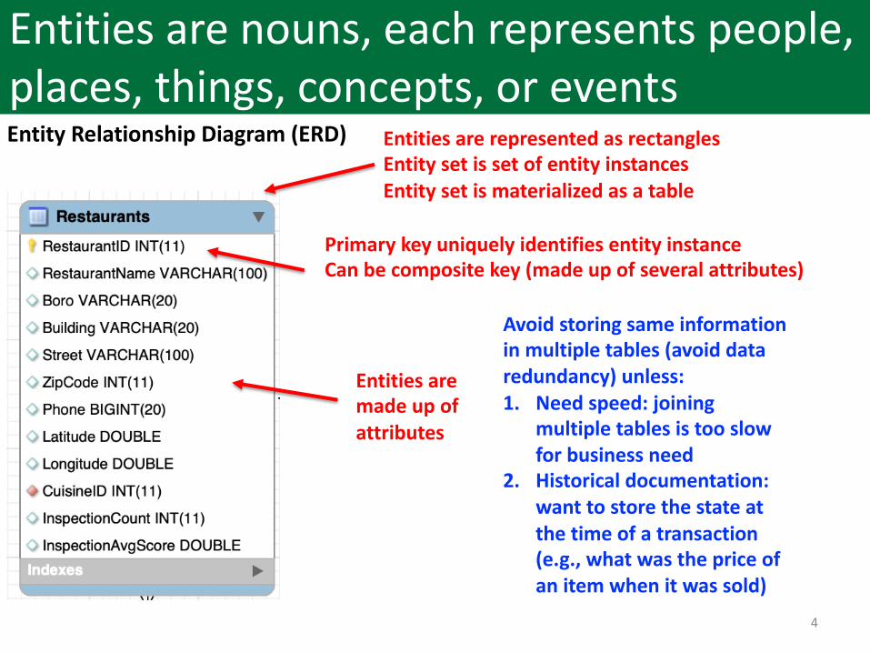
Entities are nouns, each represents people, places, things, concepts, or eventsEntity Relationship Diagram (ERD) Entities are represented as rectangles
Entity set is set of entity instancesEntity set is materialized as a table
Entities are made up of attributes
Primary key uniquely identifies entity instanceCan be composite key (made up of several attributes)
Avoid storing same information in multiple tables (avoid data redundancy) unless:1. Need speed: joining
multiple tables is too slow for business need
2. Historical documentation: want to store the state at the time of a transaction (e.g., what was the price of an item when it was sold)
5
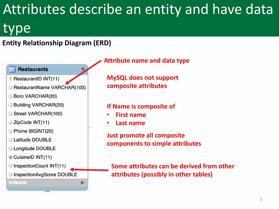
Attributes describe an entity and have data typeEntity Relationship Diagram (ERD)
Attribute name and data type
MySQL does not support composite attributes
If Name is composite of• First name• Last name
Just promote all composite components to simple attributes
Some attributes can be derived from other attributes (possibly in other tables)
6
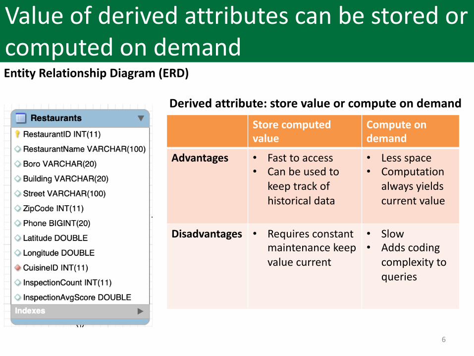
Value of derived attributes can be stored or computed on demandEntity Relationship Diagram (ERD)
Store computed value
Compute on demand
Advantages • Fast to access• Can be used to
keep track of historical data
• Less space• Computation
always yields current value
Disadvantages • Requires constant maintenance keep value current
• Slow• Adds coding
complexity to queries
Derived attribute: store value or compute on demand
7
Agenda
1. Entity Relationship (ER) models
2. Relationships• One-to-many (1:M)• One-to-one (1:1)• Many-to-many (M:N)
3. How to build an ER model
4. Reverse and forward engineering
8
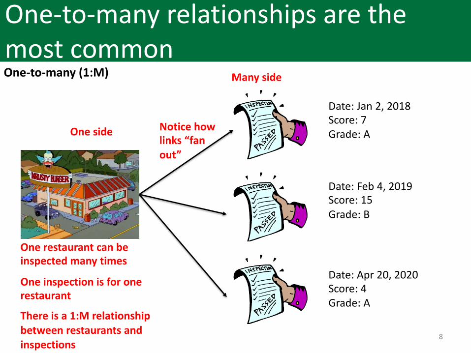
One-to-many relationships are the most commonOne-to-many (1:M)
Date: Jan 2, 2018Score: 7Grade: A
Date: Feb 4, 2019Score: 15Grade: B
Date: Apr 20, 2020Score: 4Grade: A
One restaurant can beinspected many times
One inspection is for onerestaurant
There is a 1:M relationship between restaurants and inspections
Many side
One side Notice how links “fan out”
9
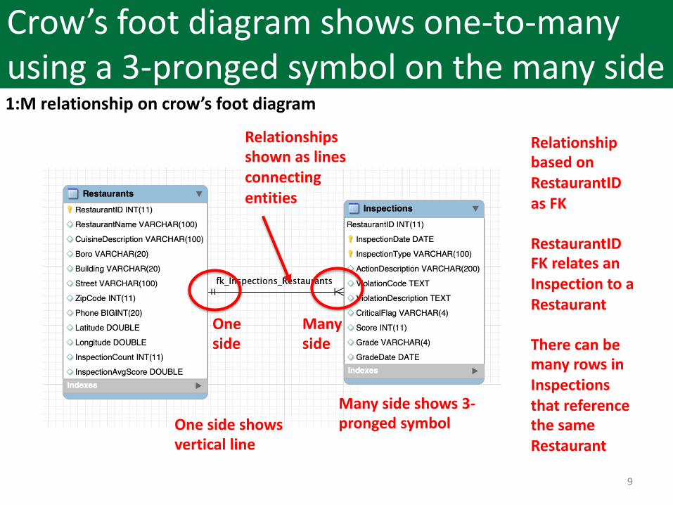
Crow’s foot diagram shows one-to-many using a 3-pronged symbol on the many side1:M relationship on crow’s foot diagram
Many side
One side
Relationships shown as lines connecting entities
Many side shows 3-pronged symbolOne side shows
vertical line
Relationship based on RestaurantIDas FK
RestaurantIDFK relates an Inspection to a Restaurant
There can be many rows in Inspections that reference the same Restaurant
10
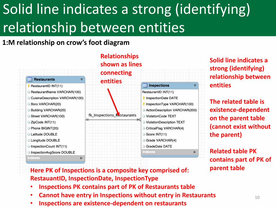
Solid line indicates a strong (identifying) relationship between entities1:M relationship on crow’s foot diagram
Relationships shown as lines connecting entities
Solid line indicates a strong (identifying) relationship between entities
The related table is existence-dependent on the parent table (cannot exist without the parent)
Related table PK contains part of PK of parent tableHere PK of Inspections is a composite key comprised of:
RestauantID, InspectionDate, InspectionType• Inspections PK contains part of PK of Restaurants table• Cannot have entry in Inspections without entry in Restaurants• Inspections are existence-dependent on restaurants
11
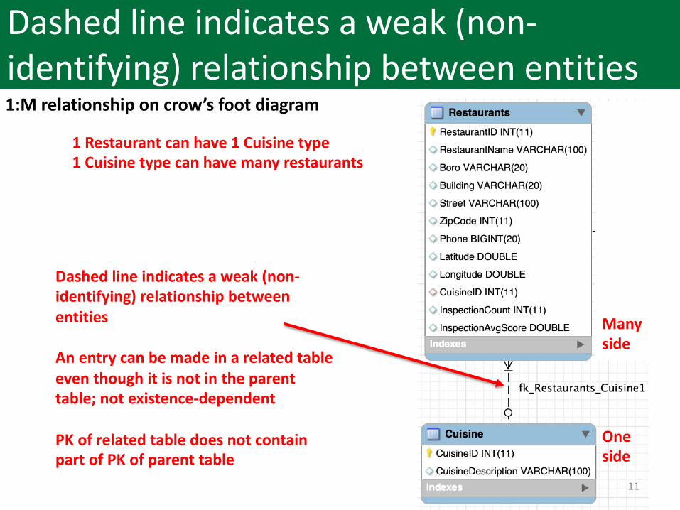
Dashed line indicates a weak (non-identifying) relationship between entities1:M relationship on crow’s foot diagram
Dashed line indicates a weak (non-identifying) relationship between entities
An entry can be made in a related table even though it is not in the parent table; not existence-dependent
PK of related table does not contain part of PK of parent table
1 Restaurant can have 1 Cuisine type1 Cuisine type can have many restaurants
Many side
One side
12
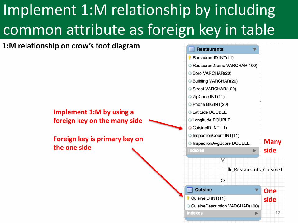
Implement 1:M relationship by including common attribute as foreign key in table1:M relationship on crow’s foot diagram
Implement 1:M by using a foreign key on the many side
Foreign key is primary key on the one side
Many side
One side
13
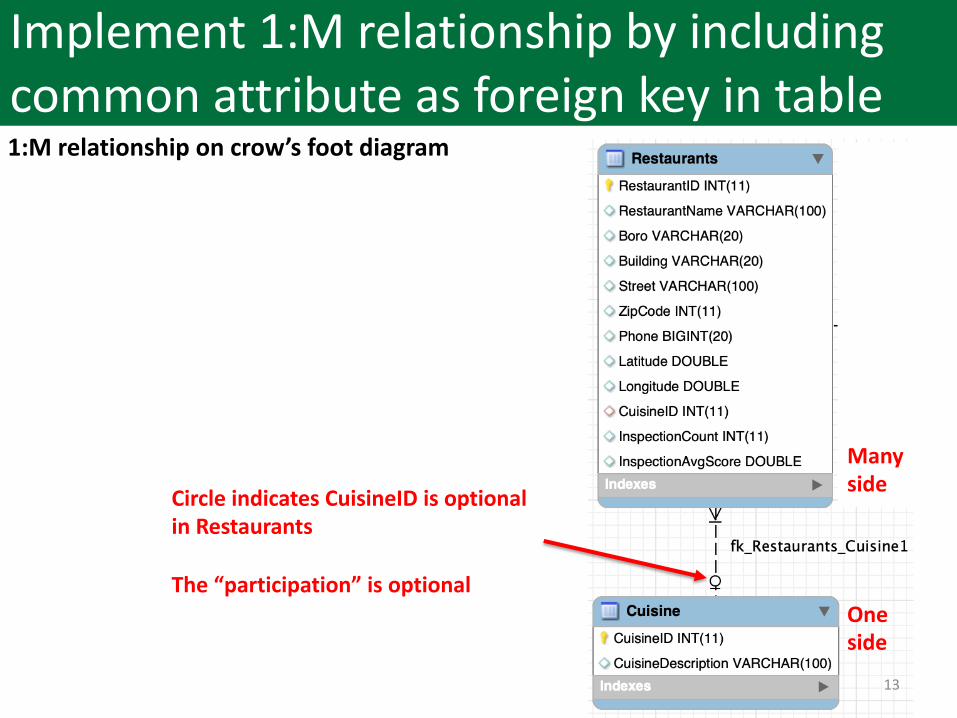
Implement 1:M relationship by including common attribute as foreign key in table1:M relationship on crow’s foot diagram
Circle indicates CuisineID is optionalin Restaurants
The “participation” is optional
Many side
One side
14
Agenda
1. Entity Relationship (ER) models
2. Relationships• One-to-many (1:M)• One-to-one (1:1)• Many-to-many (M:N)
3. How to build an ER model
4. Reverse and forward engineering
15
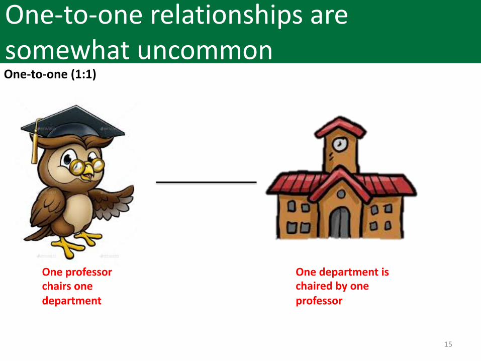
One-to-one relationships are somewhat uncommonOne-to-one (1:1)
One department is chaired by one professor
One professor chairs one department
16
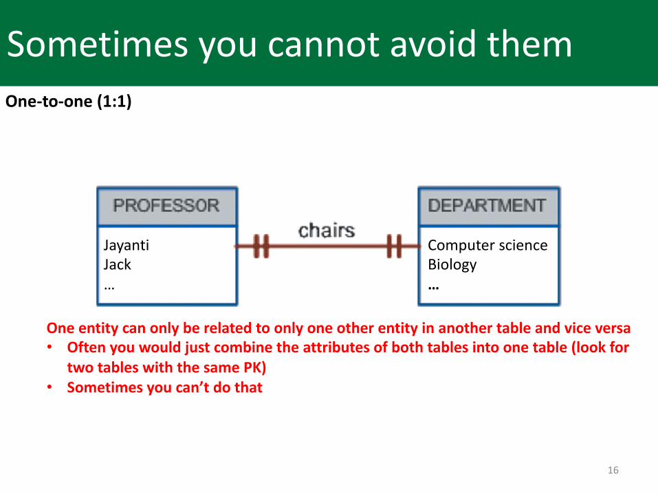
Sometimes you cannot avoid themOne-to-one (1:1)
One entity can only be related to only one other entity in another table and vice versa• Often you would just combine the attributes of both tables into one table (look for
two tables with the same PK)• Sometimes you can’t do that
Computer science Biology…
JayantiJack…
17
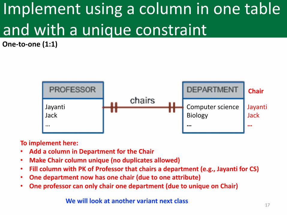
Implement using a column in one table and with a unique constraint One-to-one (1:1)
To implement here:• Add a column in Department for the Chair• Make Chair column unique (no duplicates allowed)• Fill column with PK of Professor that chairs a department (e.g., Jayanti for CS)• One department now has one chair (due to one attribute)• One professor can only chair one department (due to unique on Chair)
Chair
Computer science JayantiBiology Jack… …
We will look at another variant next class
JayantiJack…
18
Agenda
1. Entity Relationship (ER) models
2. Relationships• One-to-many (1:M)• One-to-one (1:1)• Many-to-many (M:N)
3. How to build an ER model
4. Reverse and forward engineering
19
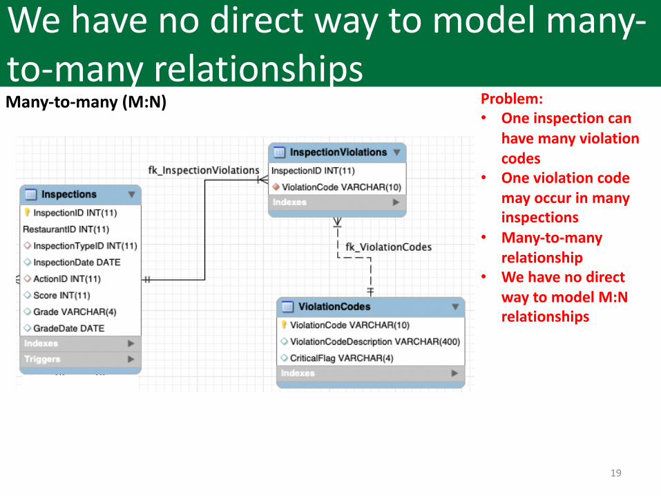
We have no direct way to model many-to-many relationshipsMany-to-many (M:N) Problem:
• One inspection can have many violation codes
• One violation code may occur in many inspections
• Many-to-many relationship
• We have no direct way to model M:N relationships
20
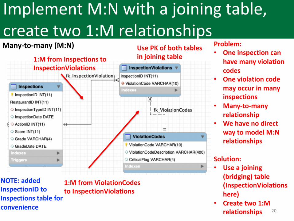
Implement M:N with a joining table, create two 1:M relationshipsMany-to-many (M:N) Problem:
• One inspection can have many violation codes
• One violation code may occur in many inspections
• Many-to-many relationship
• We have no direct way to model M:N relationships
Solution:• Use a joining
(bridging) table (InspectionViolationshere)
• Create two 1:M relationships
1:M from Inspections to InspectionViolations
1:M from ViolationCodesto InspectionViolations
Use PK of both tables in joining table
NOTE: added InspectionID to Inspections table for convenience
21
Agenda
1. Entity Relationship (ER) models
2. Relationships
3. How to build an ER model
4. Reverse and forward engineering
22
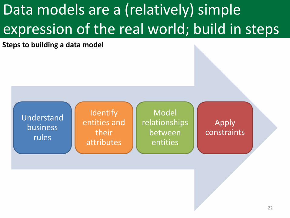
Data models are a (relatively) simple expression of the real world; build in steps
Understand business
rules
Identify entities and
their attributes
Model relationships
between entities
Apply constraints
Steps to building a data model
23
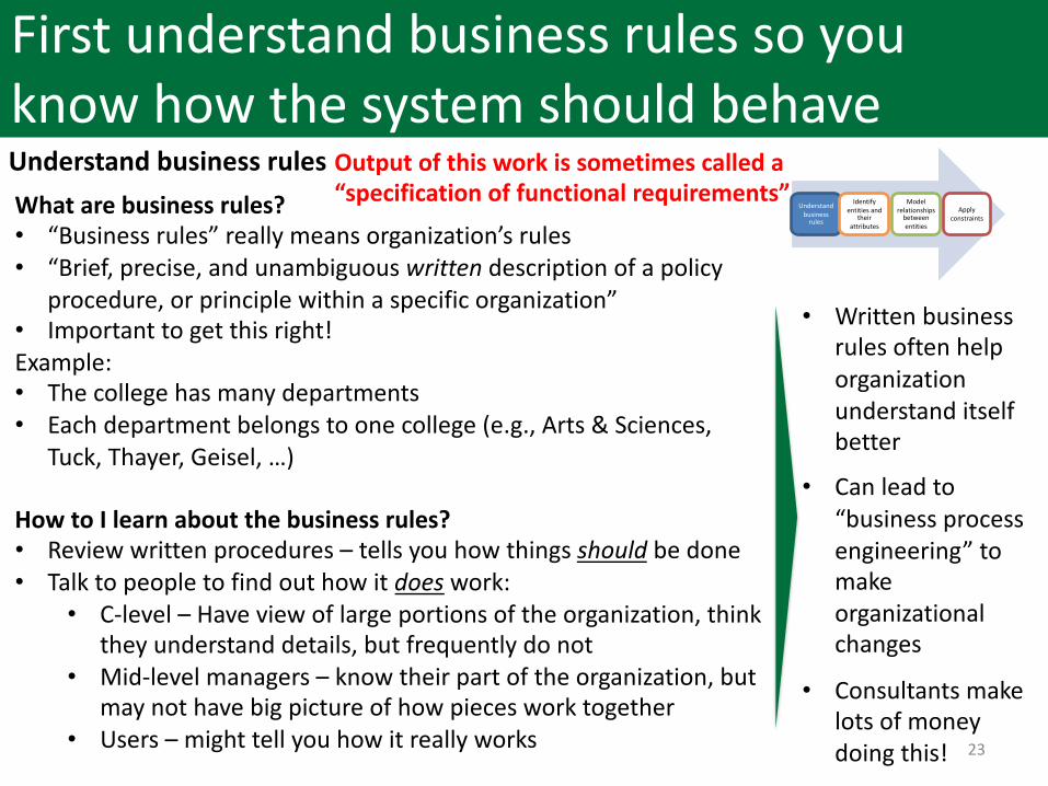
First understand business rules so you know how the system should behaveUnderstand business rulesWhat are business rules?• “Business rules” really means organization’s rules• “Brief, precise, and unambiguous written description of a policy
procedure, or principle within a specific organization”• Important to get this right!Example:• The college has many departments• Each department belongs to one college (e.g., Arts & Sciences,
Tuck, Thayer, Geisel, …)
How to I learn about the business rules?• Review written procedures – tells you how things should be done• Talk to people to find out how it does work:
• C-level – Have view of large portions of the organization, think they understand details, but frequently do not
• Mid-level managers – know their part of the organization, but may not have big picture of how pieces work together
• Users – might tell you how it really works
Understand business
rules
Identify entities and
their attributes
Model relationships
between entities
Apply constraints
• Written business rules often help organization understand itself better
• Can lead to “business process engineering” to make organizational changes
• Consultants make lots of money doing this!
Output of this work is sometimes called a “specification of functional requirements”
24
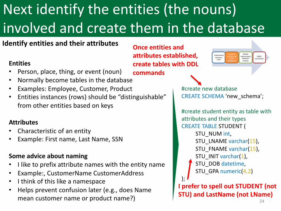
Next identify the entities (the nouns) involved and create them in the databaseIdentify entities and their attributes
Entities• Person, place, thing, or event (noun)• Normally become tables in the database• Examples: Employee, Customer, Product• Entities instances (rows) should be “distinguishable”
from other entities based on keys
Attributes • Characteristic of an entity• Example: First name, Last Name, SSN
Some advice about naming• I like to prefix attribute names with the entity name• Example:, CustomerName CustomerAddress• I think of this like a namespace• Helps prevent confusion later (e.g., does Name
mean customer name or product name?)
Understand business
rules
Identify entities and
their attributes
Model relationships
between entities
Apply constraints
#create new databaseCREATE SCHEMA ‘new_schema’;
#create student entity as table with attributes and their typesCREATE TABLE STUDENT (
STU_NUM int,STU_LNAME varchar(15),STU_FNAME varchar(15),STU_INIT varchar(1),STU_DOB datetime,STU_GPA numeric(4,2)
);
Once entities and attributes established, create tables with DDL commands
I prefer to spell out STUDENT (not STU) and LastName (not LName)
25
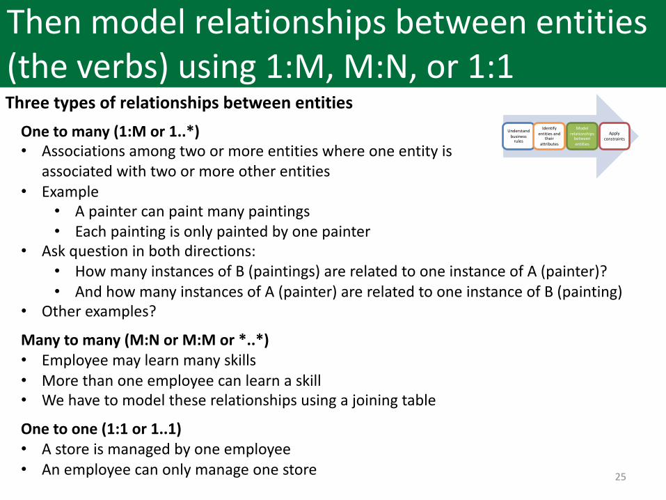
Then model relationships between entities (the verbs) using 1:M, M:N, or 1:1Three types of relationships between entities
One to many (1:M or 1..*)• Associations among two or more entities where one entity is
associated with two or more other entities• Example
• A painter can paint many paintings• Each painting is only painted by one painter
• Ask question in both directions:• How many instances of B (paintings) are related to one instance of A (painter)?• And how many instances of A (painter) are related to one instance of B (painting)
• Other examples?
Many to many (M:N or M:M or *..*)• Employee may learn many skills• More than one employee can learn a skill• We have to model these relationships using a joining table
One to one (1:1 or 1..1)• A store is managed by one employee• An employee can only manage one store
Understand business
rules
Identify entities and
their attributes
Model relationships
between entities
Apply constraints
26
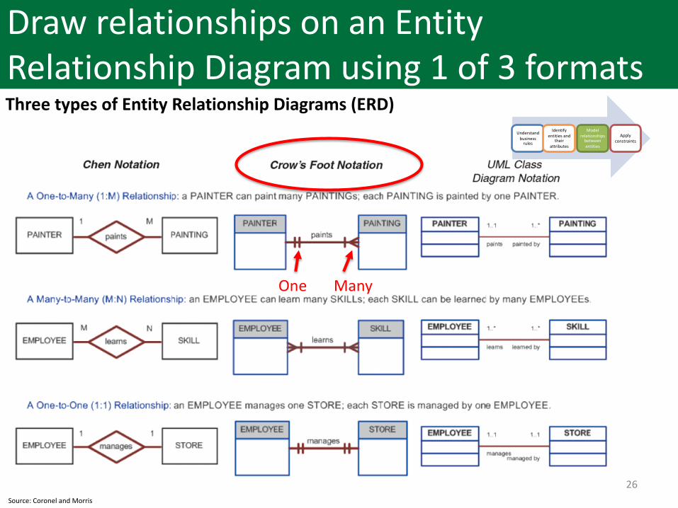
Draw relationships on an Entity Relationship Diagram using 1 of 3 formatsThree types of Entity Relationship Diagrams (ERD)
Understand business
rules
Identify entities and
their attributes
Model relationships
between entities
Apply constraints
Source: Coronel and Morris
ManyOne
27
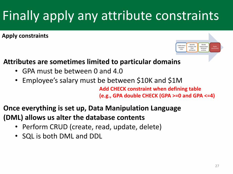
Finally apply any attribute constraints
Understand business
rules
Identify entities and
their attributes
Model relationships
between entities
Apply constraints
Apply constraints
Attributes are sometimes limited to particular domains• GPA must be between 0 and 4.0• Employee’s salary must be between $10K and $1M
Once everything is set up, Data Manipulation Language (DML) allows us alter the database contents• Perform CRUD (create, read, update, delete)• SQL is both DML and DDL
Add CHECK constraint when defining table (e.g., GPA double CHECK (GPA >=0 and GPA <=4)
28
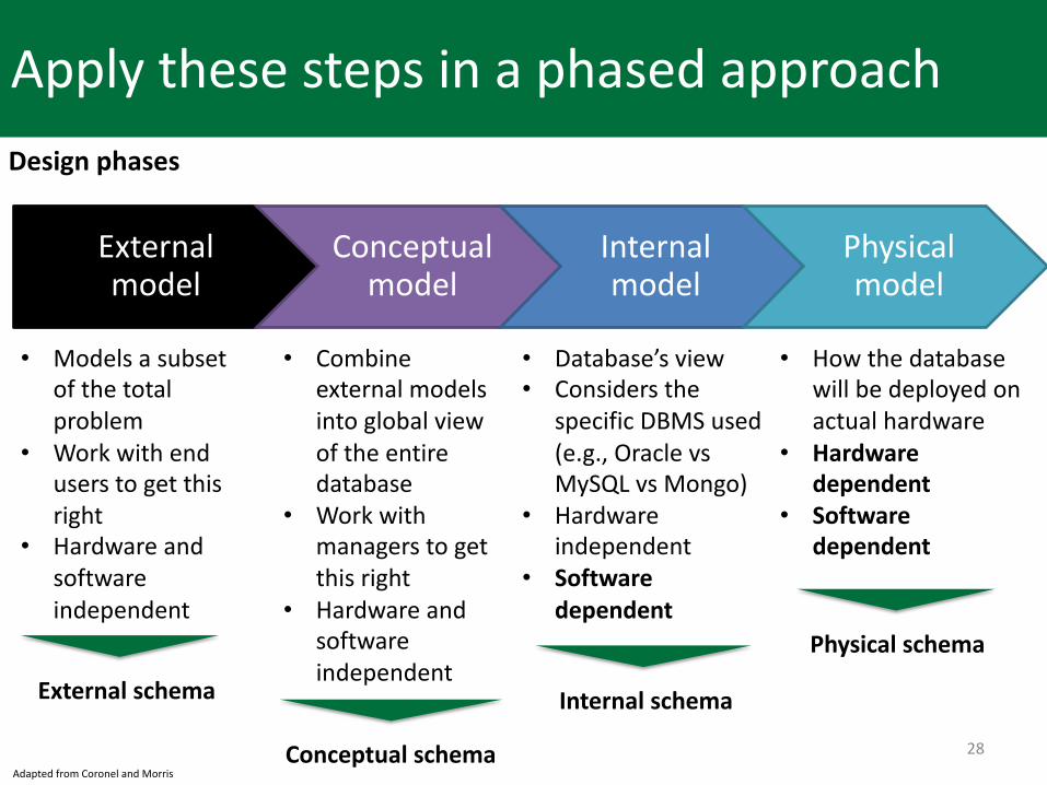
Apply these steps in a phased approach
External model
Conceptual model
Internal model
Physical model
• Models a subset of the total problem
• Work with end users to get this right
• Hardware and software independent
Adapted from Coronel and Morris
• Combine external models into global view of the entire database
• Work with managers to get this right
• Hardware and software independent
• Database’s view• Considers the
specific DBMS used (e.g., Oracle vs MySQL vs Mongo)
• Hardware independent
• Software dependent
• How the database will be deployed on actual hardware
• Hardware dependent
• Software dependent
External schema
Conceptual schema
Internal schema
Physical schema
Design phases
29
Agenda
1. Entity Relationship (ER) models
2. Relationships
3. How to build an ER model
4. Reverse and forward engineering
30
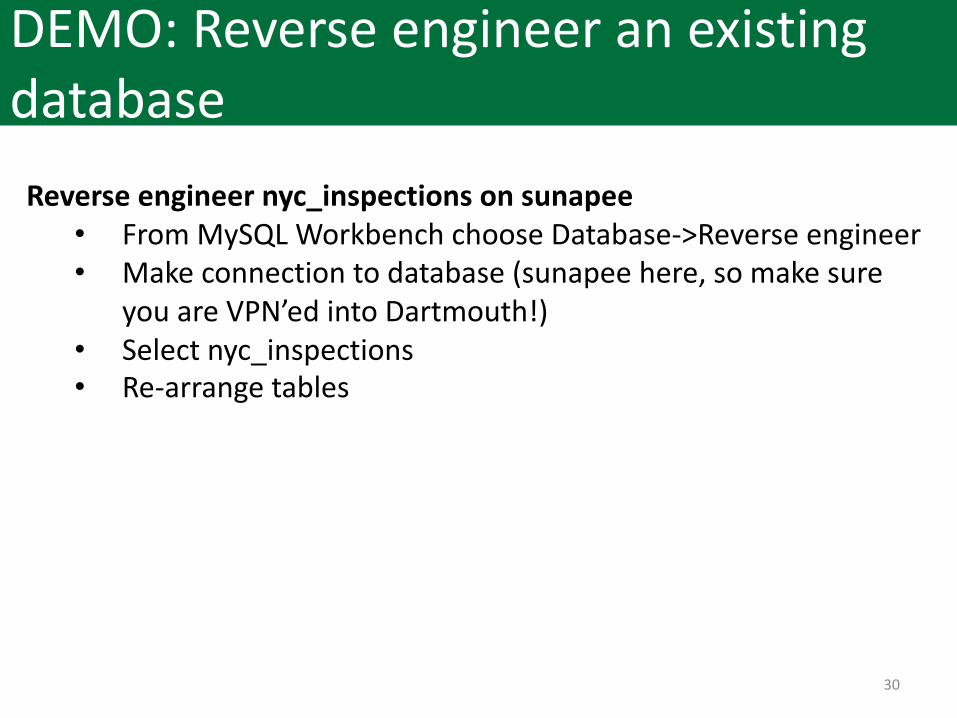
DEMO: Reverse engineer an existing database
Reverse engineer nyc_inspections on sunapee• From MySQL Workbench choose Database->Reverse engineer• Make connection to database (sunapee here, so make sure
you are VPN’ed into Dartmouth!)• Select nyc_inspections• Re-arrange tables
31
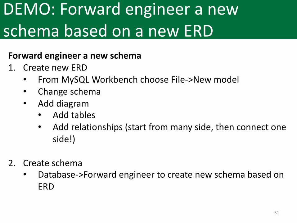
DEMO: Forward engineer a new schema based on a new ERD
Forward engineer a new schema1. Create new ERD• From MySQL Workbench choose File->New model• Change schema• Add diagram• Add tables• Add relationships (start from many side, then connect one
side!)
2. Create schema• Database->Forward engineer to create new schema based on
ERD
32
Practice
Forward engineer a database according to the following rules to track painters, paintings, and galleries for a famous art museum: • A painting is painted by a specific artist and that painting is
exhibited in a specific gallery• A gallery can exhibit many paintings, but each painting can be
exhibited in only one gallery • Similarly, a painting is painted by a single painter, but each
painter can paint many paintings

33