Embed Size (px)
Citation preview
CS 543: Computer GraphicsLecture 8 (Part II): Hidden Surface Removal
Emmanuel Agu
Hidden surface Removal
n Drawing polygonal faces on screen consumes CPU cyclesn We cannot see every surface in scenen To save time, draw only surfaces we seen Surfaces we cannot see and their elimination methods:
n Occluded surfaces: hidden surface removal (visibility)n Back faces: back face cullingn Faces outside view volume: viewing frustrum culling
n Definitions:n Object space techniques: applied before vertices are
mapped to pixelsn Image space techniques: applied after vertices have been
rasterized
Visibility (hidden surface removal)
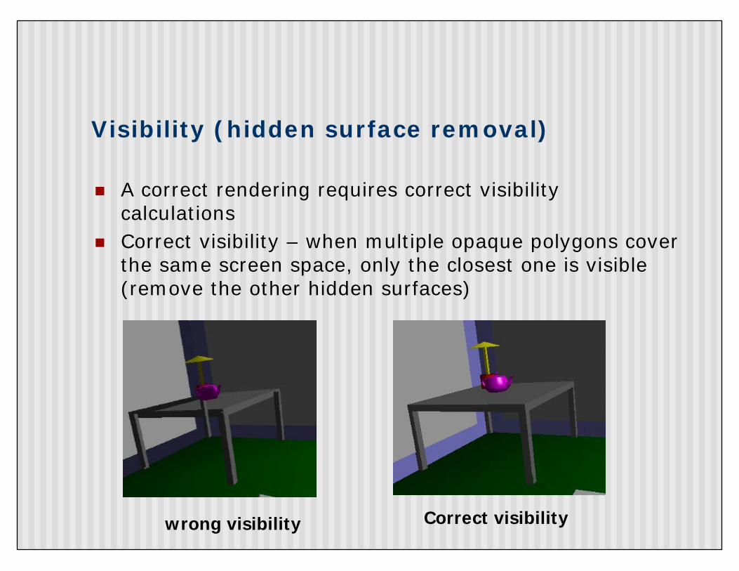
n A correct rendering requires correct visibility calculations
n Correct visibility – when multiple opaque polygons cover the same screen space, only the closest one is visible (remove the other hidden surfaces)
wrong visibility Correct visibility
Visibility (hidden surface removal)
n Goal: determine which objects are visible to the eyen Determine what colors to use to paint the pixels
n Active research subject - lots of algorithms have been proposed in the past (and is still a hot topic)
Visibility (hidden surface removal)
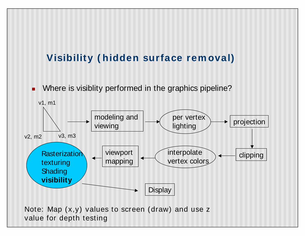
n Where is visiblity performed in the graphics pipeline?
modeling and viewing
v1, m1
v2, m2 v3, m3
per vertex lighting projection
clippinginterpolate vertex colors
viewport mapping
RasterizationtexturingShadingvisibility
Display
Note: Map (x,y) values to screen (draw) and use z value for depth testing

OpenGL - Image Space Approach
§ Determine which of the n objects is visible to each pixel on the image plane
for (each pixel in the image) {determine the object closest to the pixel draw the pixel using the object’s color
}
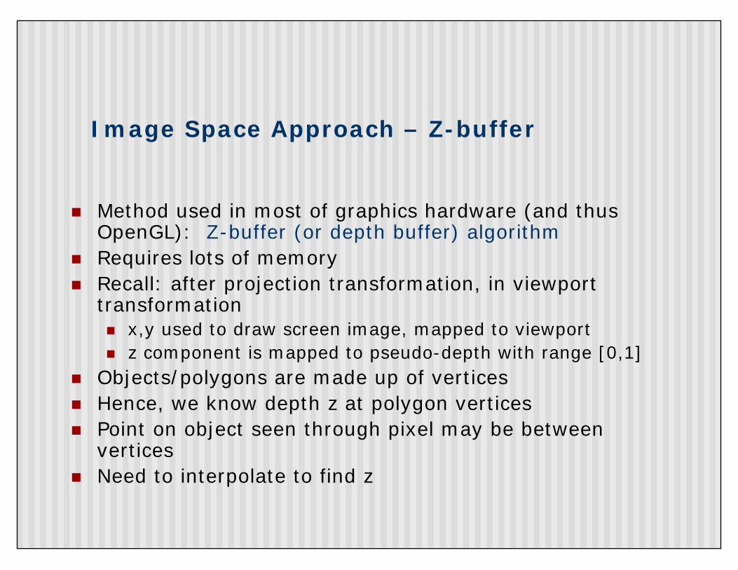
Image Space Approach – Z-buffer
n Method used in most of graphics hardware (and thus OpenGL): Z-buffer (or depth buffer) algorithm
n Requires lots of memoryn Recall: after projection transformation, in viewport
transformationn x,y used to draw screen image, mapped to viewportn z component is mapped to pseudo-depth with range [0,1]
n Objects/polygons are made up of verticesn Hence, we know depth z at polygon verticesn Point on object seen through pixel may be between
verticesn Need to interpolate to find z
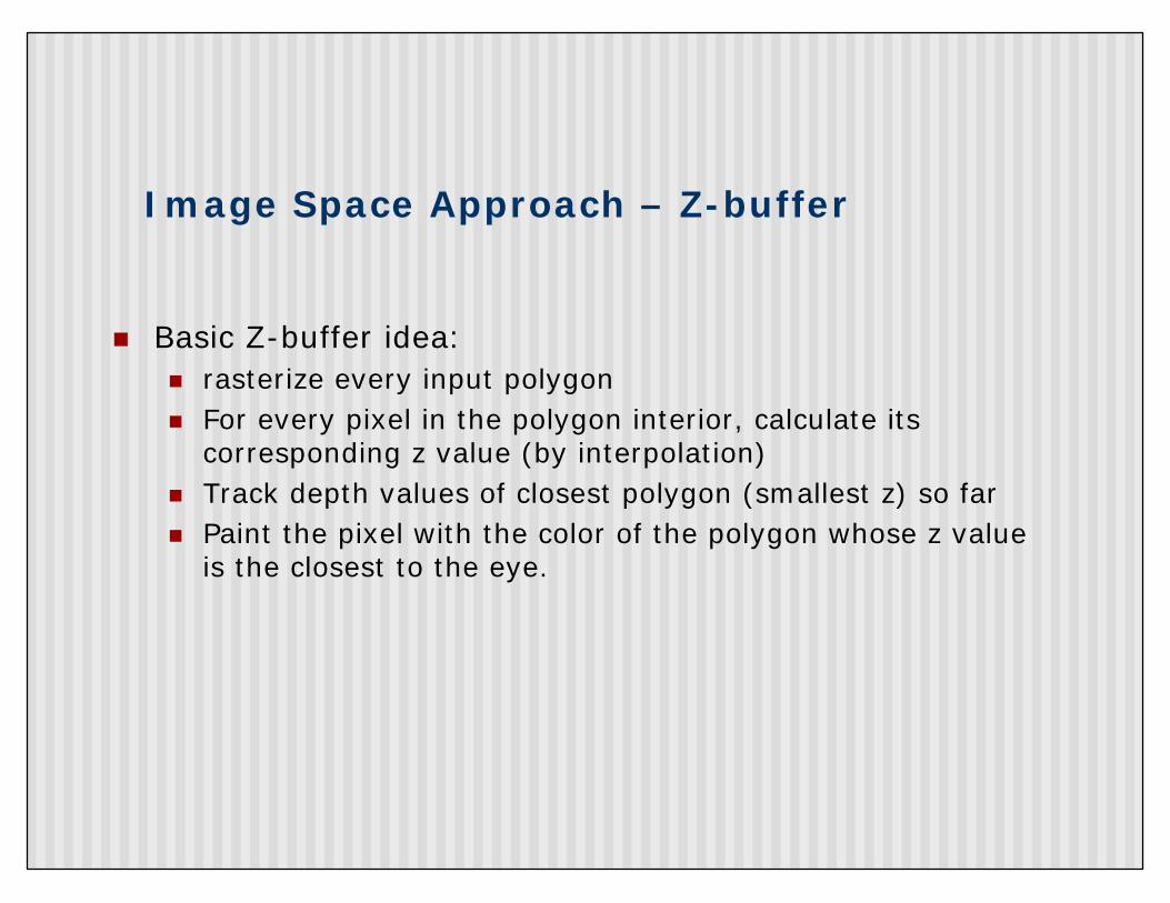
Image Space Approach – Z-buffer
n Basic Z-buffer idea: n rasterize every input polygonn For every pixel in the polygon interior, calculate its
corresponding z value (by interpolation) n Track depth values of closest polygon (smallest z) so farn Paint the pixel with the color of the polygon whose z value
is the closest to the eye.
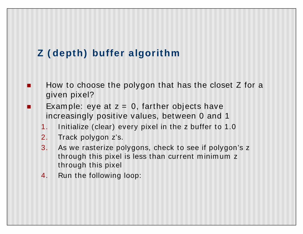
Z (depth) buffer algorithm
n How to choose the polygon that has the closet Z for a given pixel?
n Example: eye at z = 0, farther objects have increasingly positive values, between 0 and 1
1. Initialize (clear) every pixel in the z buffer to 1.02. Track polygon z’s. 3. As we rasterize polygons, check to see if polygon’s z
through this pixel is less than current minimum z through this pixel
4. Run the following loop:
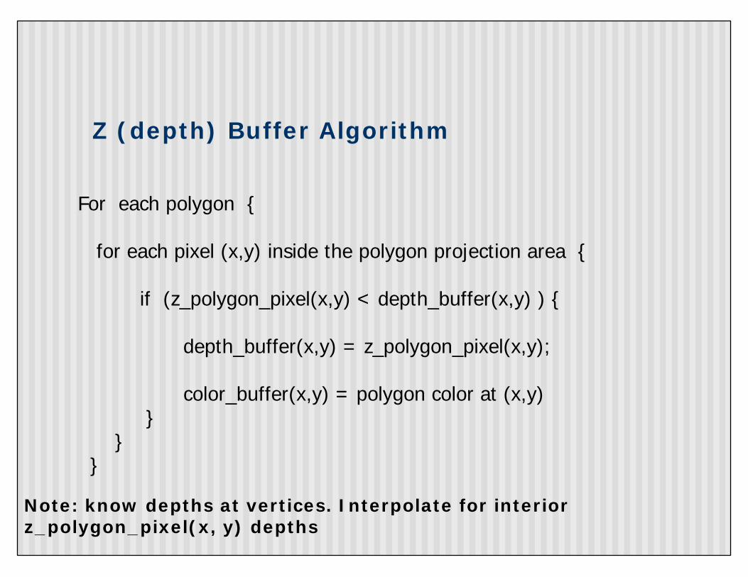
Z (depth) Buffer Algorithm
For each polygon {
for each pixel (x,y) inside the polygon projection area {
if (z_polygon_pixel(x,y) < depth_buffer(x,y) ) {
depth_buffer(x,y) = z_polygon_pixel(x,y);
color_buffer(x,y) = polygon color at (x,y)}
}}
Note: know depths at vertices. Interpolate for interior z_polygon_pixel(x, y) depths
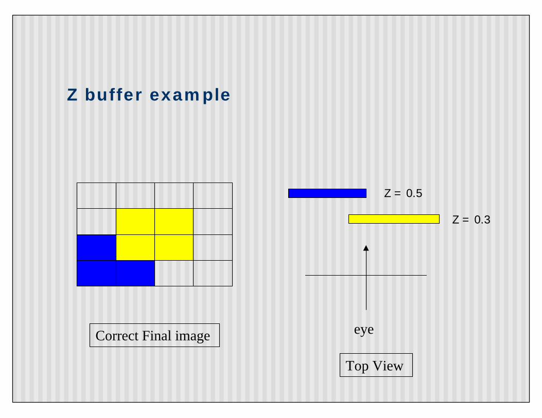
Z buffer example
eye
Z = 0.3
Z = 0.5
Top View
Correct Final image
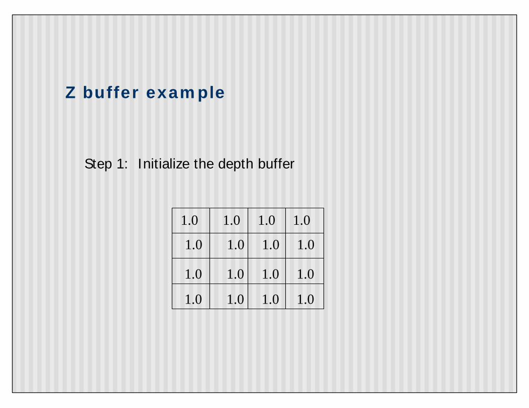
Z buffer example
1.0 1.0 1.0 1.0
Step 1: Initialize the depth buffer
1.0 1.0 1.0 1.0
1.0 1.0 1.0 1.0
1.0 1.0 1.0 1.0
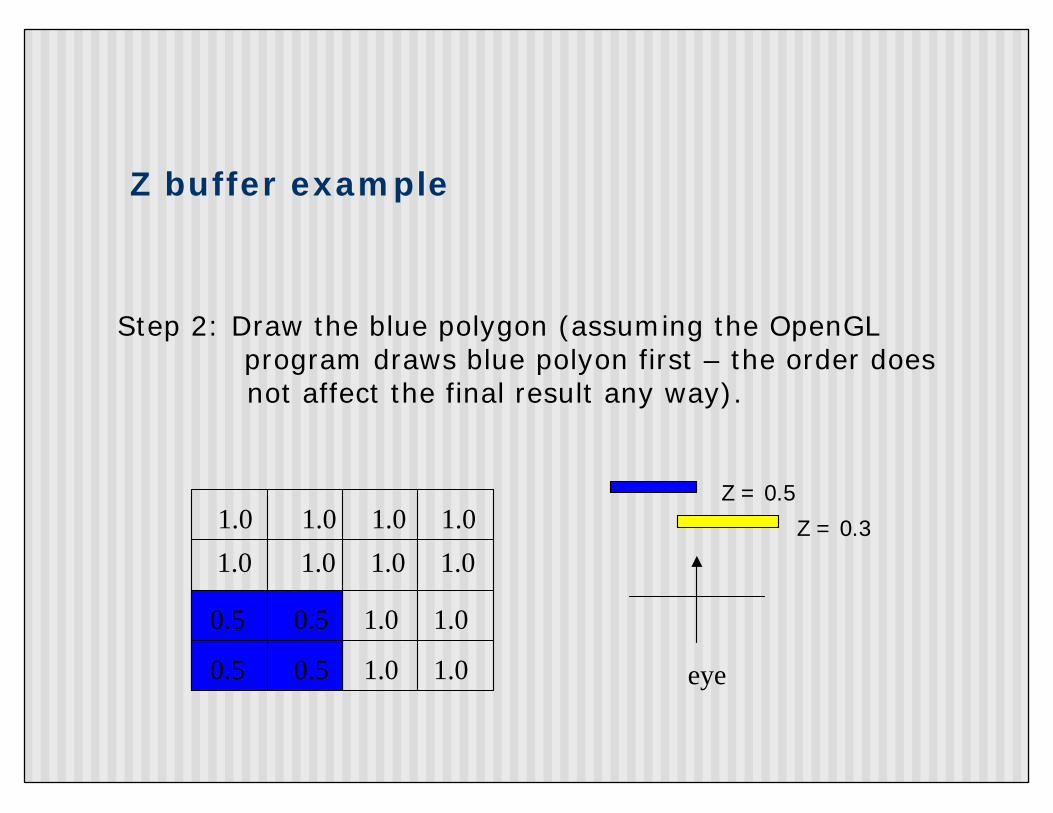
Z buffer example
Step 2: Draw the blue polygon (assuming the OpenGL program draws blue polyon first – the order does not affect the final result any way).
eye
Z = 0.3
Z = 0.51.0 1.0 1.0 1.0
1.0 1.0 1.0 1.0
0.5 0.5 1.0 1.0
0.5 0.5 1.0 1.0
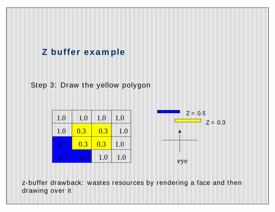
Z buffer example
Step 3: Draw the yellow polygon
eye
Z = 0.3
Z = 0.5
1.0 0.3 0.3 1.0
0.5 0.3 0.3 1.0
0.5 0.5 1.0 1.0
z-buffer drawback: wastes resources by rendering a face and then drawing over it
1.0 1.0 1.0 1.0
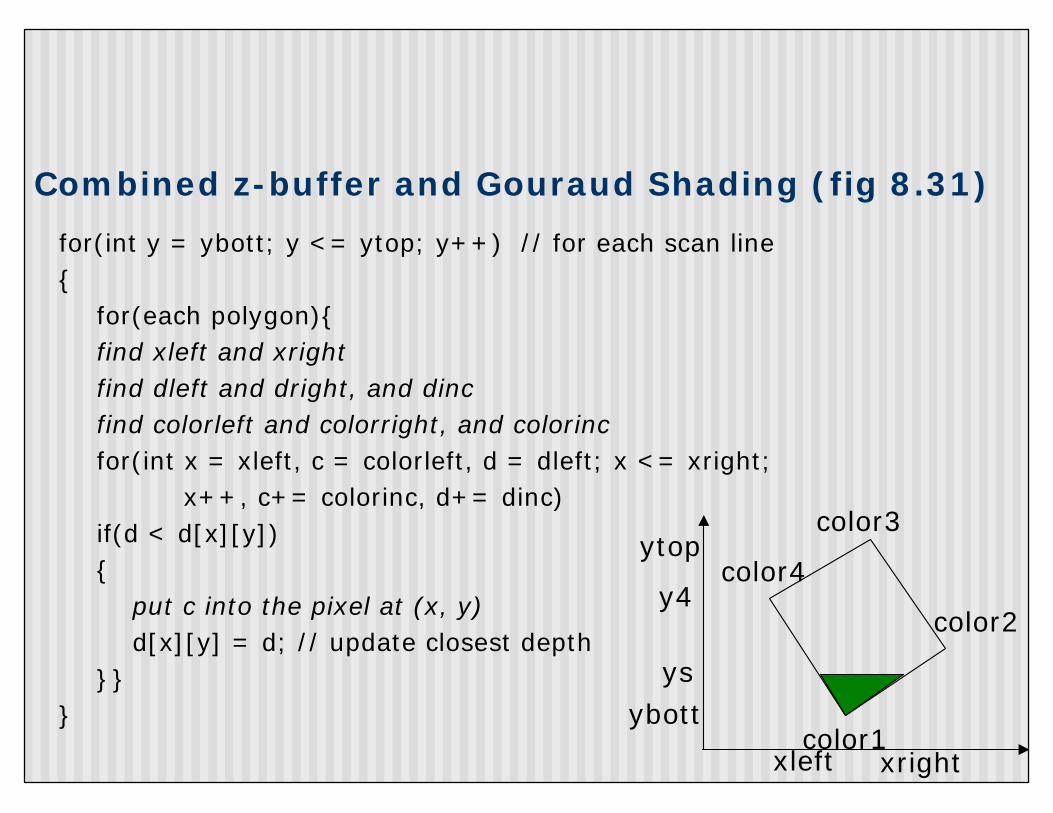
Combined z-buffer and Gouraud Shading (fig 8.31)
for(int y = ybott; y <= ytop; y++) // for each scan line{
for(each polygon){find xleft and xrightfind dleft and dright, and dincfind colorleft and colorright, and colorincfor(int x = xleft, c = colorleft, d = dleft; x <= xright;
x++, c+= colorinc, d+= dinc)if(d < d[x][y]){
put c into the pixel at (x, y)d[x][y] = d; // update closest depth
}} }
color3
color4
color1
color2
ybottys
y4
ytop
xrightxleft

Z-Buffer Depth Compression
n Recall that we chose parameters a and b to map z from range [near, far] to pseudodepth range[0,1]
n This mapping is almost linear close to eyen Non-linear further from eye, approaches asymptoten Also limited number of bitsn Thus, two z values close to far plane may map to same
pseudodepth: Errors!!
Actual z
-Pz
1
-1
N
F
PzbaPz
−+
NFNFa −
+−=
NFFNb −
−−= 2
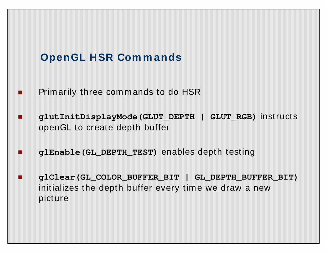
OpenGL HSR Commands
n Primarily three commands to do HSR
n glutInitDisplayMode(GLUT_DEPTH | GLUT_RGB) instructs openGL to create depth buffer
n glEnable(GL_DEPTH_TEST) enables depth testing
n glClear(GL_COLOR_BUFFER_BIT | GL_DEPTH_BUFFER_BIT)initializes the depth buffer every time we draw a new picture
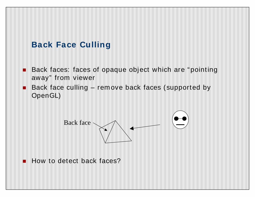
Back Face Culling
n Back faces: faces of opaque object which are “pointing away” from viewer
n Back face culling – remove back faces (supported by OpenGL)
n How to detect back faces?
Back face
Back Face Culling
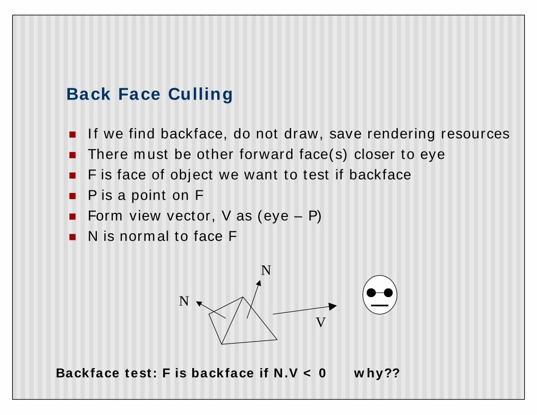
n If we find backface, do not draw, save rendering resourcesn There must be other forward face(s) closer to eyen F is face of object we want to test if backfacen P is a point on Fn Form view vector, V as (eye – P)n N is normal to face F
NV
N
Backface test: F is backface if N.V < 0 why??
Back Face Culling: Draw mesh front faces
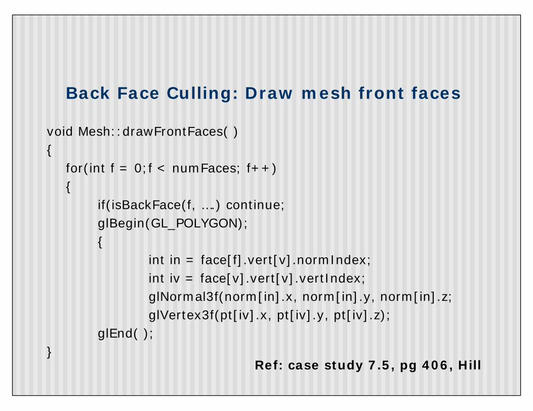
void Mesh::drawFrontFaces( ) {
for(int f = 0;f < numFaces; f++){
if(isBackFace(f, ….) continue;glBegin(GL_POLYGON);{
int in = face[f].vert[v].normIndex; int iv = face[v].vert[v].vertIndex;glNormal3f(norm[in].x, norm[in].y, norm[in].z;glVertex3f(pt[iv].x, pt[iv].y, pt[iv].z);
glEnd( );}
Ref: case study 7.5, pg 406, Hill
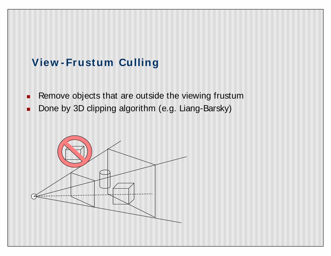
View-Frustum Culling
n Remove objects that are outside the viewing frustumn Done by 3D clipping algorithm (e.g. Liang-Barsky)
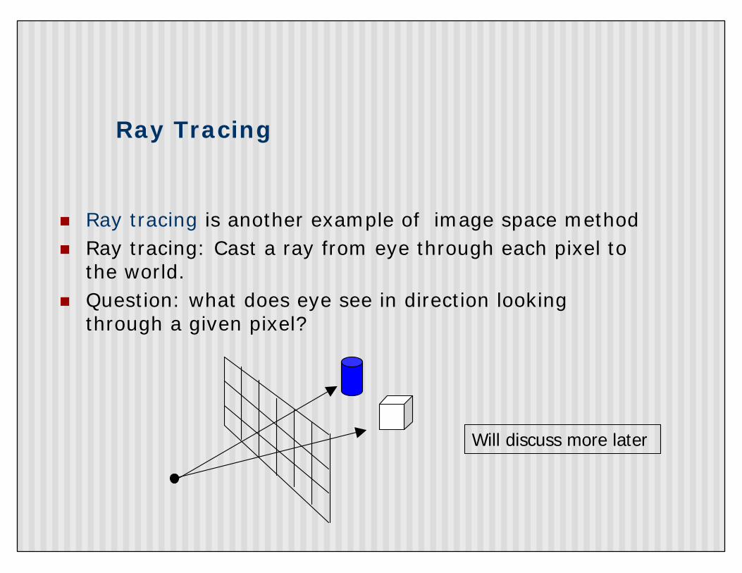
Ray Tracing
n Ray tracing is another example of image space methodn Ray tracing: Cast a ray from eye through each pixel to
the world. n Question: what does eye see in direction looking
through a given pixel?
Will discuss more later
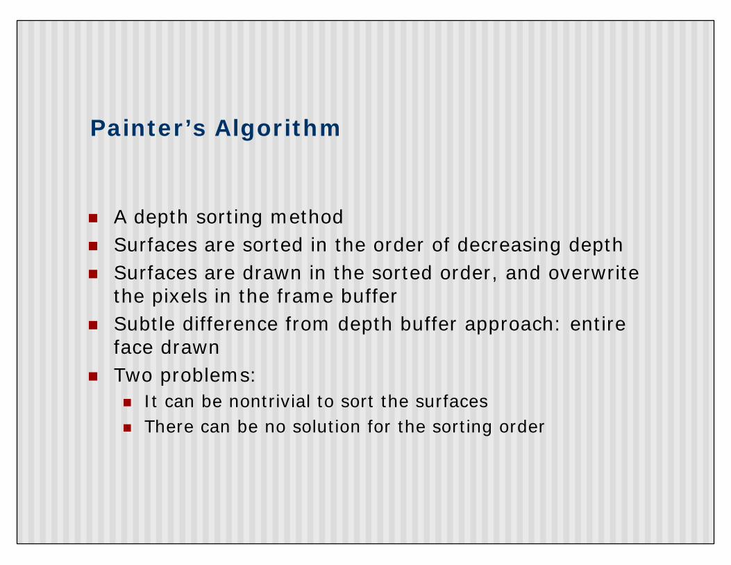
Painter’s Algorithm
n A depth sorting method n Surfaces are sorted in the order of decreasing depth n Surfaces are drawn in the sorted order, and overwrite
the pixels in the frame buffer n Subtle difference from depth buffer approach: entire
face drawnn Two problems:
n It can be nontrivial to sort the surfaces n There can be no solution for the sorting order
References
n Hill, section 8.5