Embed Size (px)
Citation preview
CS 450: COMPUTER GRAPHICS
CLIPPING AND SCREEN MAPPING
SPRING 2016
DR. MICHAEL J. REALE

INTRODUCTION TO CLIPPING
CLIPPING DEFINED
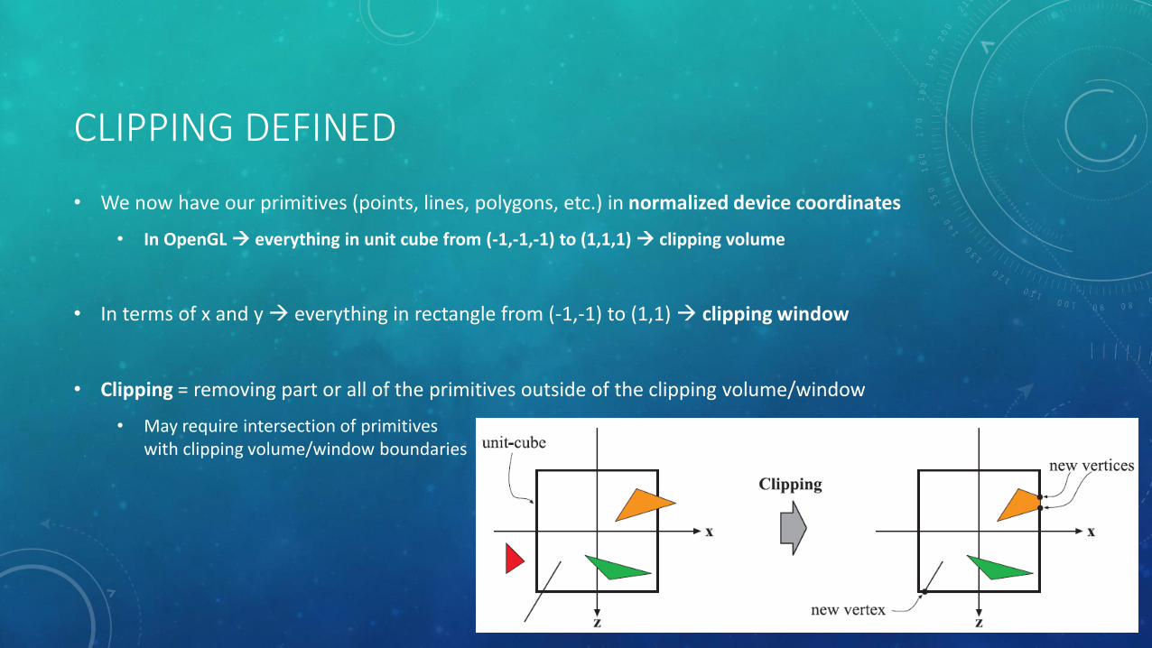
• We now have our primitives (points, lines, polygons, etc.) in normalized device coordinates
• In OpenGL everything in unit cube from (-1,-1,-1) to (1,1,1) clipping volume
• In terms of x and y everything in rectangle from (-1,-1) to (1,1) clipping window
• Clipping = removing part or all of the primitives outside of the clipping volume/window
• May require intersection of primitives with clipping volume/window boundaries
CLIPPING WINDOW VS. VIEWPORT
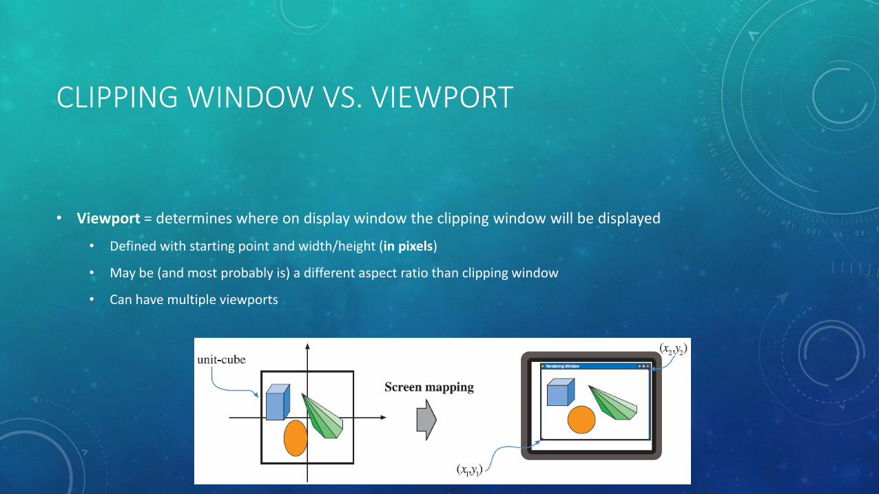
• Viewport = determines where on display window the clipping window will be displayed
• Defined with starting point and width/height (in pixels)
• May be (and most probably is) a different aspect ratio than clipping window
• Can have multiple viewports

CLIPPING ALGORITHMS
• Clipping algorithms can be 2D or 3D
• The clipping algorithm also may clip:
• Points
• Lines
• Fill-Areas (Polygons)
• Curves
• Text
• We will start with 2D clipping algorithms first.
2D CLIPPING ALGORITHMS: INTRODUCTION

POINT CLIPPING IN 2D
• Not much to say here; as long as the point coordinates are within the window, draw the point:
• Otherwise, do not draw the point
• Useful for particle systems
maxmin
maxmin
yyy
xxx
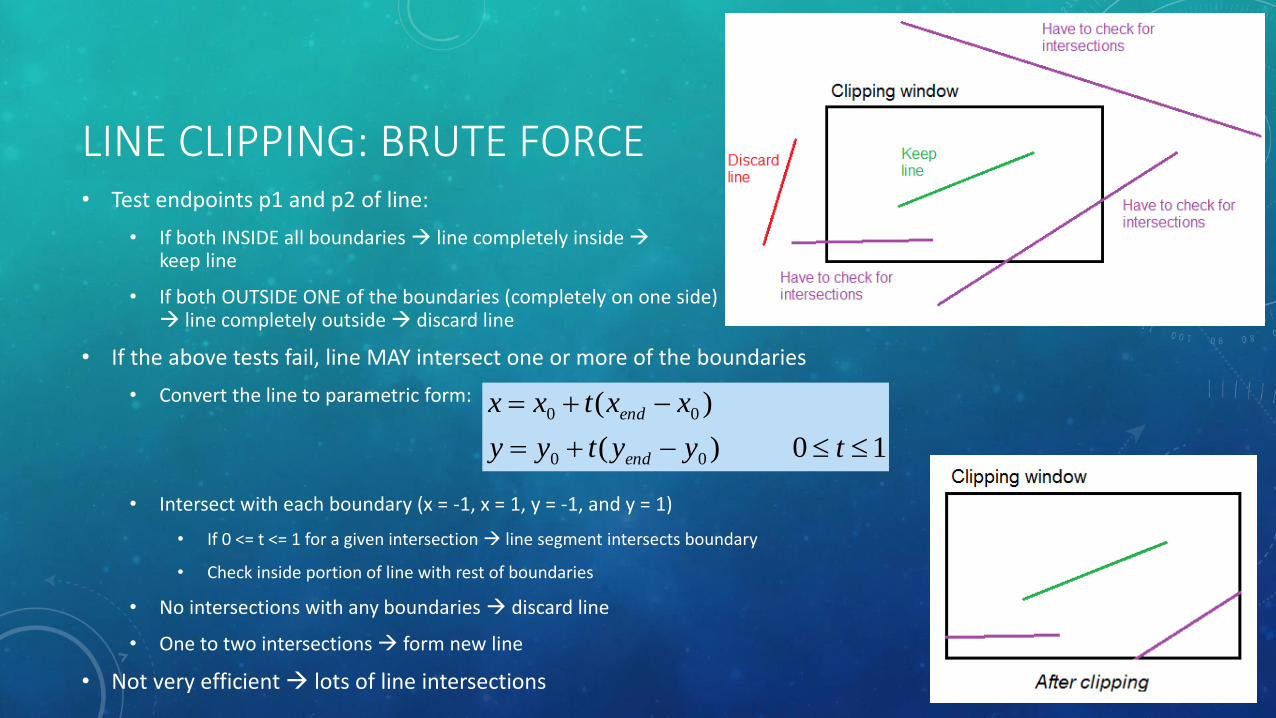
LINE CLIPPING: BRUTE FORCE• Test endpoints p1 and p2 of line:
• If both INSIDE all boundaries line completely inside keep line
• If both OUTSIDE ONE of the boundaries (completely on one side) line completely outside discard line
• If the above tests fail, line MAY intersect one or more of the boundaries
• Convert the line to parametric form:
• Intersect with each boundary (x = -1, x = 1, y = -1, and y = 1)
• If 0 <= t <= 1 for a given intersection line segment intersects boundary
• Check inside portion of line with rest of boundaries
• No intersections with any boundaries discard line
• One to two intersections form new line
• Not very efficient lots of line intersections
10 )(
)(
00
00
tyytyy
xxtxx
end
end

COHEN-SUTHERLAND LINE CLIPPING

INTRODUCTION
• Cohen-Sutherland line clipping
• One of the earliest algorithms variations still widely used
• Does more tests before doing intersection calculations
• Assumes rectangular clipping region
“Without the fun, none of uswould go on.” – Ivan Sutherland
Danny Cohen
BASIC IDEA
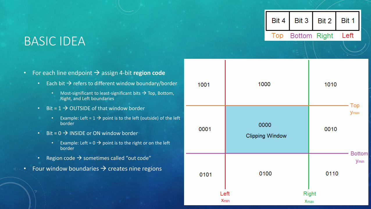
• For each line endpoint assign 4-bit region code
• Each bit refers to different window boundary/border
• Most-significant to least-significant bits Top, Bottom, Right, and Left boundaries
• Bit = 1 OUTSIDE of that window border
• Example: Left = 1 point is to the left (outside) of the left border
• Bit = 0 INSIDE or ON window border
• Example: Left = 0 point is to the right or on the left border
• Region code sometimes called “out code”
• Four window boundaries creates nine regions
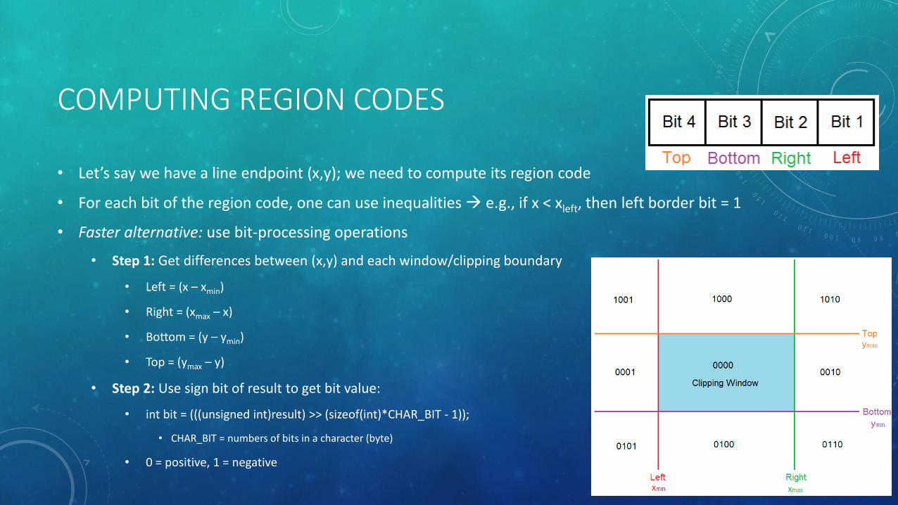
COMPUTING REGION CODES
• Let’s say we have a line endpoint (x,y); we need to compute its region code
• For each bit of the region code, one can use inequalities e.g., if x < xleft, then left border bit = 1
• Faster alternative: use bit-processing operations
• Step 1: Get differences between (x,y) and each window/clipping boundary
• Left = (x – xmin)
• Right = (xmax – x)
• Bottom = (y – ymin)
• Top = (ymax – y)
• Step 2: Use sign bit of result to get bit value:
• int bit = (((unsigned int)result) >> (sizeof(int)*CHAR_BIT - 1));
• CHAR_BIT = numbers of bits in a character (byte)
• 0 = positive, 1 = negative
CHECKING ENDPOINTS
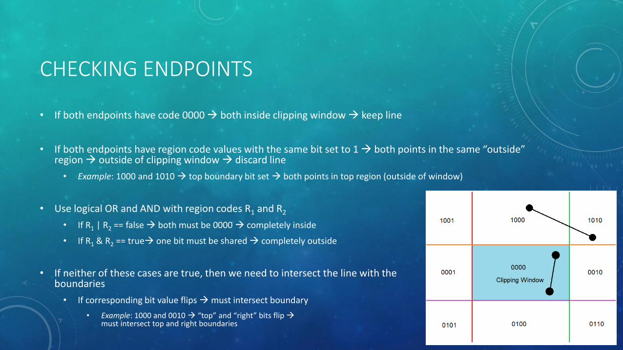
• If both endpoints have code 0000 both inside clipping window keep line
• If both endpoints have region code values with the same bit set to 1 both points in the same “outside” region outside of clipping window discard line
• Example: 1000 and 1010 top boundary bit set both points in top region (outside of window)
• Use logical OR and AND with region codes R1 and R2
• If R1 | R2 == false both must be 0000 completely inside
• If R1 & R2 == true one bit must be shared completely outside
• If neither of these cases are true, then we need to intersect the line with the boundaries
• If corresponding bit value flips must intersect boundary
• Example: 1000 and 0010 “top” and “right” bits flip must intersect top and right boundaries
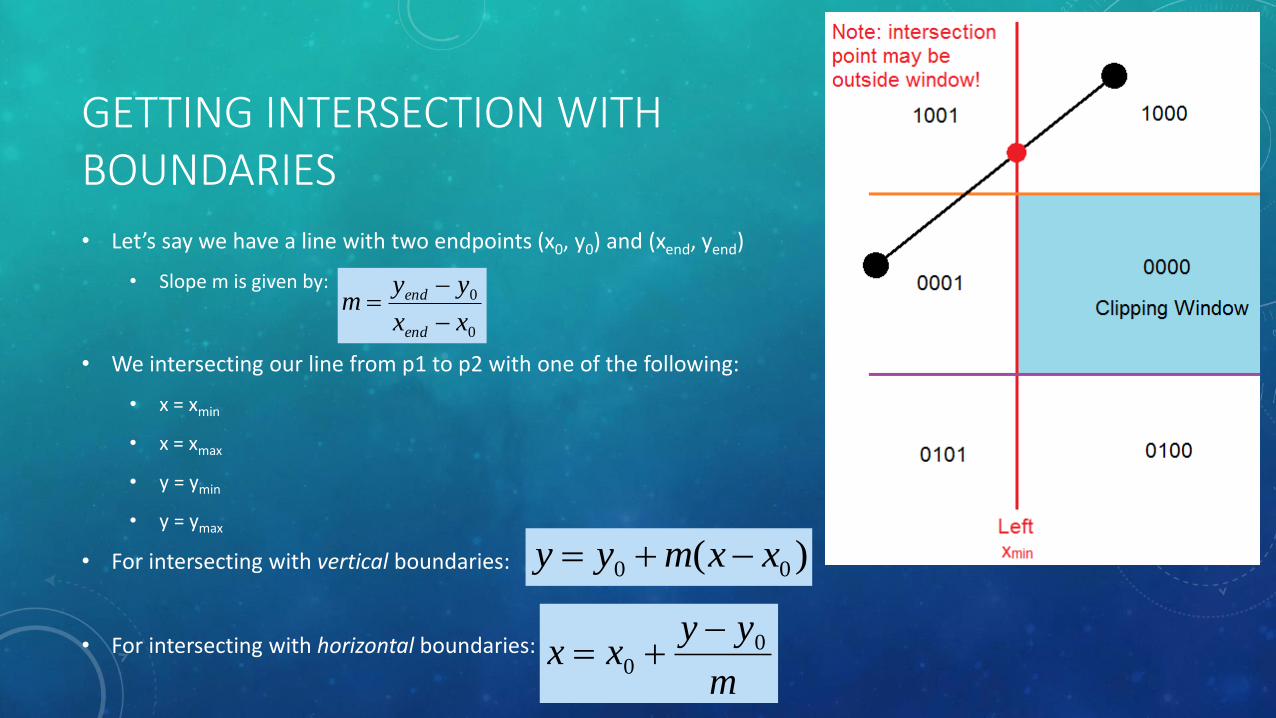
GETTING INTERSECTION WITH BOUNDARIES
• Let’s say we have a line with two endpoints (x0, y0) and (xend, yend)
• Slope m is given by:
• We intersecting our line from p1 to p2 with one of the following:
• x = xmin
• x = xmax
• y = ymin
• y = ymax
• For intersecting with vertical boundaries:
• For intersecting with horizontal boundaries:
)( 00 xxmyy
0
0
xx
yym
end
end
m
yyxx 0
0
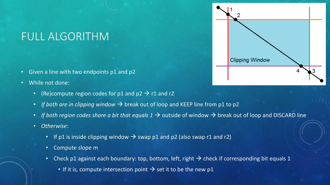
FULL ALGORITHM
• Given a line with two endpoints p1 and p2
• While not done:
• (Re)compute region codes for p1 and p2 r1 and r2
• If both are in clipping window break out of loop and KEEP line from p1 to p2
• If both region codes share a bit that equals 1 outside of window break out of loop and DISCARD line
• Otherwise:
• If p1 is inside clipping window swap p1 and p2 (also swap r1 and r2)
• Compute slope m
• Check p1 against each boundary: top, bottom, left, right check if corresponding bit equals 1
• If it is, compute intersection point set it to be the new p1
NON-RECTANGULAR CLIPPING?
• One downside of Cohen-Sutherland line clipping is that it only works for rectangular clipping regions
• VERY common, but there might be cases where you want a non-rectangular clipping region

LIANG-BARSKY LINE CLIPPING
INTRODUCTION
• Liang-Barsky Line Clipping
• Does even MORE testing before intersection calculations faster
• Uses parametric line equations
• Can be used with non-rectangular clipping regions
PARAMETRIC LINES AND CLIPPING
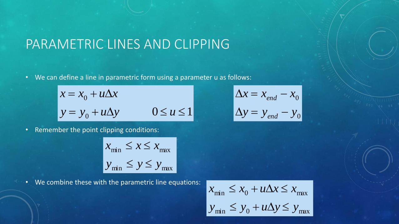
• We can define a line in parametric form using a parameter u as follows:
• Remember the point clipping conditions:
• We combine these with the parametric line equations:
10 0
0
uyuyy
xuxx
0
0
yyy
xxx
end
end
maxmin
maxmin
yyy
xxx
max0min
max0min
yyuyy
xxuxx
TESTING CONDITIONS
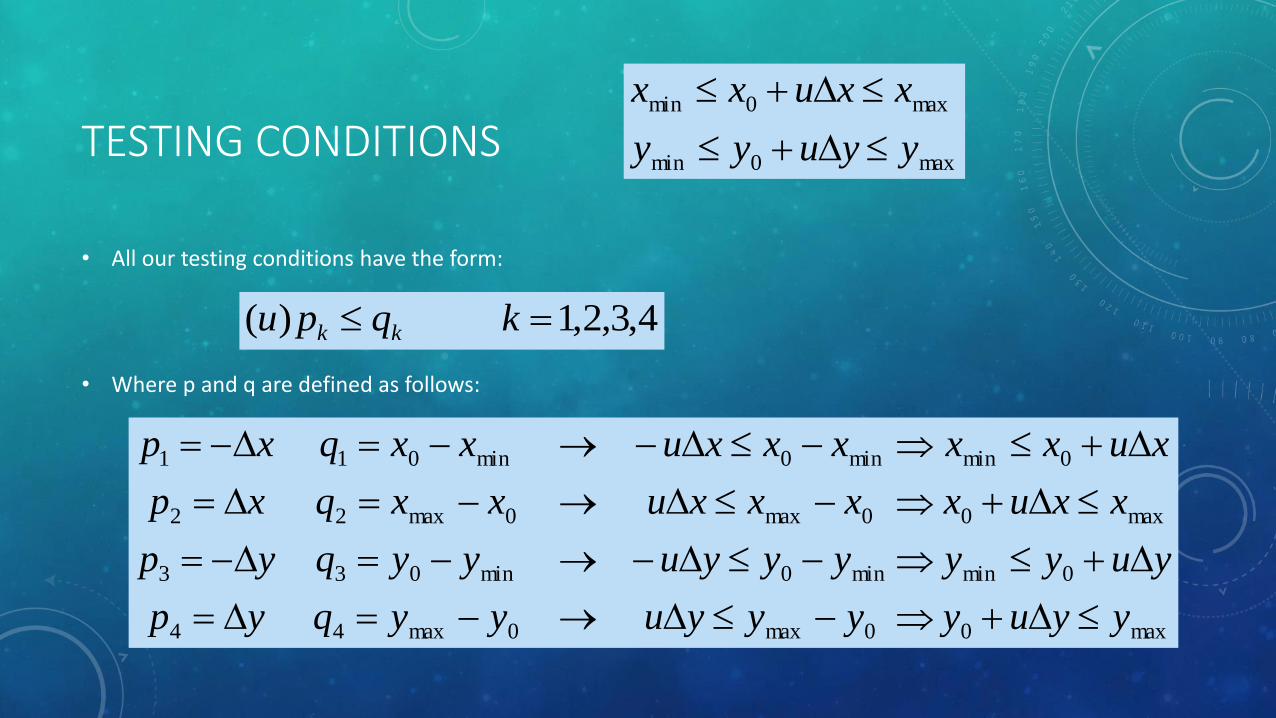
• All our testing conditions have the form:
• Where p and q are defined as follows:
max0min
max0min
yyuyy
xxuxx
4,3,2,1 )( kqpu kk
max0
0min
max0
0min
0max0max44
min0min033
0max0max22
min0min011
yyuy
yuyy
xxux
xuxx
yyyuyyqyp
yyyuyyqyp
xxxuxxqxp
xxxuxxqxp
COMPUTING THE INTERSECTION POINT
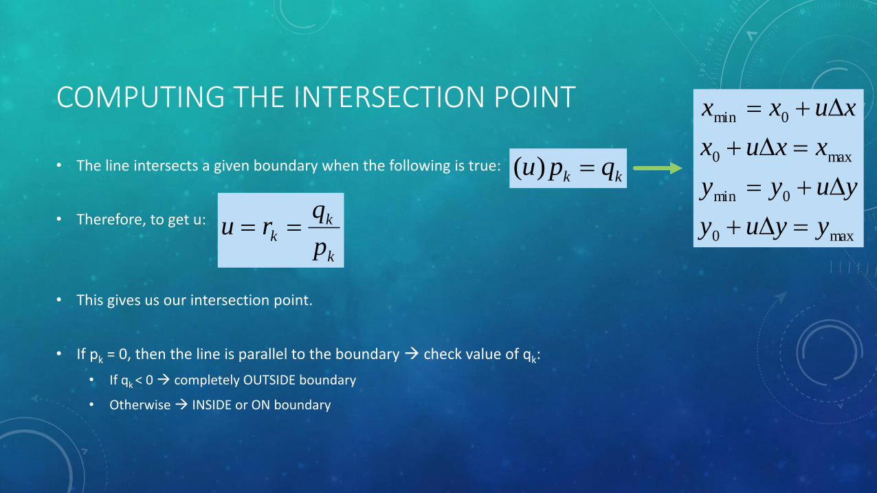
• The line intersects a given boundary when the following is true:
• Therefore, to get u:
• This gives us our intersection point.
• If pk = 0, then the line is parallel to the boundary check value of qk:
• If qk < 0 completely OUTSIDE boundary
• Otherwise INSIDE or ON boundary
kk qpu )(
max0
0min
max0
0min
yyuy
yuyy
xxux
xuxx
k
kk
p
qru

VALUE OF PK
• If pk = 0 line is parallel to the boundary
• If pk < 0 line goes from OUTSIDE to INSIDE the boundary
• If pk > 0 line goes from INSIDE to OUTSIDE the boundary
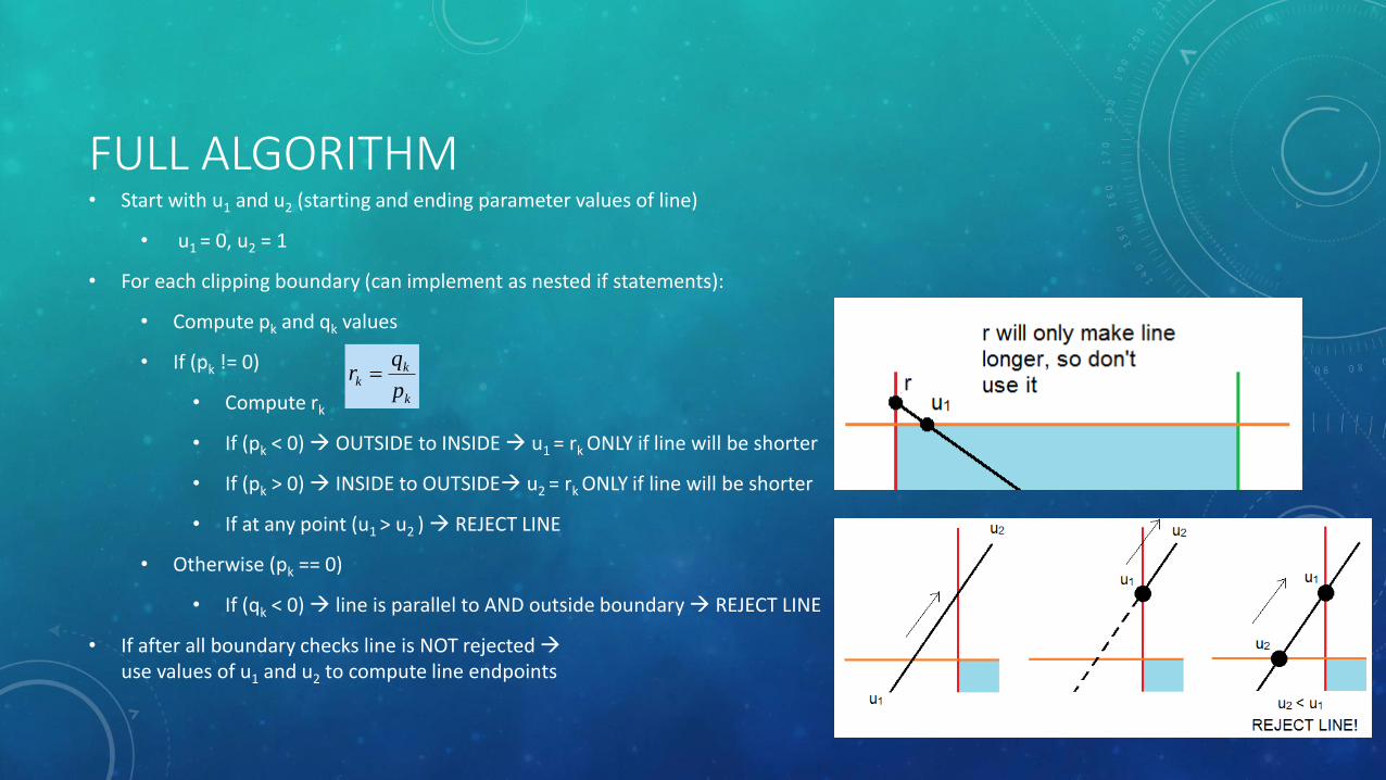
FULL ALGORITHM• Start with u1 and u2 (starting and ending parameter values of line)
• u1 = 0, u2 = 1
• For each clipping boundary (can implement as nested if statements):
• Compute pk and qk values
• If (pk != 0)
• Compute rk
• If (pk < 0) OUTSIDE to INSIDE u1 = rk ONLY if line will be shorter
• If (pk > 0) INSIDE to OUTSIDE u2 = rk ONLY if line will be shorter
• If at any point (u1 > u2 ) REJECT LINE
• Otherwise (pk == 0)
• If (qk < 0) line is parallel to AND outside boundary REJECT LINE
• If after all boundary checks line is NOT rejected use values of u1 and u2 to compute line endpoints
k
kk
p
qr
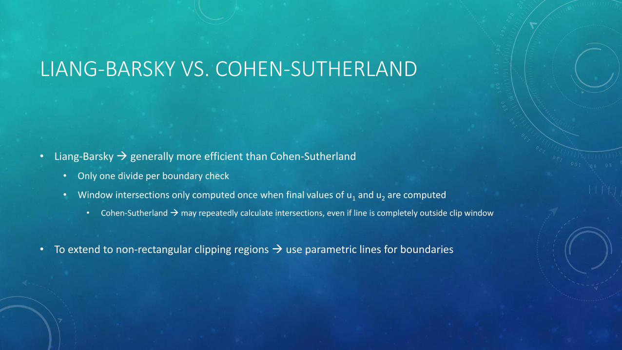
LIANG-BARSKY VS. COHEN-SUTHERLAND
• Liang-Barsky generally more efficient than Cohen-Sutherland
• Only one divide per boundary check
• Window intersections only computed once when final values of u1 and u2 are computed
• Cohen-Sutherland may repeatedly calculate intersections, even if line is completely outside clip window
• To extend to non-rectangular clipping regions use parametric lines for boundaries

POLYGON FILL-AREA CLIPPING: INTRODUCTION
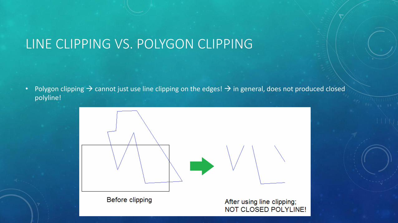
LINE CLIPPING VS. POLYGON CLIPPING
• Polygon clipping cannot just use line clipping on the edges! in general, does not produced closed polyline!
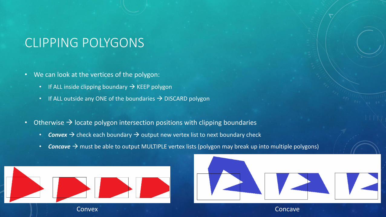
CLIPPING POLYGONS
• We can look at the vertices of the polygon:
• If ALL inside clipping boundary KEEP polygon
• If ALL outside any ONE of the boundaries DISCARD polygon
• Otherwise locate polygon intersection positions with clipping boundaries
• Convex check each boundary output new vertex list to next boundary check
• Concave must be able to output MULTIPLE vertex lists (polygon may break up into multiple polygons)
Convex Concave

SUTHERLAND-HODGMAN POLYGON CLIPPING

INTRODUCTION
• Sutherland-Hodgman Polygon Clipping
• By default, only handles convex polygons only produces one list of vertices
• Can be modified to do concave as well
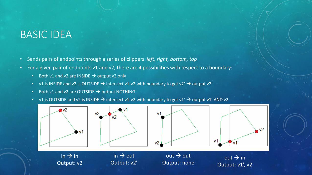
BASIC IDEA
• Sends pairs of endpoints through a series of clippers: left, right, bottom, top
• For a given pair of endpoints v1 and v2, there are 4 possibilities with respect to a boundary:
• Both v1 and v2 are INSIDE output v2 only
• v1 is INSIDE and v2 is OUTSIDE intersect v1-v2 with boundary to get v2’ output v2’
• Both v1 and v2 are OUTSIDE output NOTHING
• v1 is OUTSIDE and v2 is INSIDE intersect v1-v2 with boundary to get v1’ output v1’ AND v2
in inOutput: v2
in outOutput: v2’
out outOutput: none
out inOutput: v1’, v2
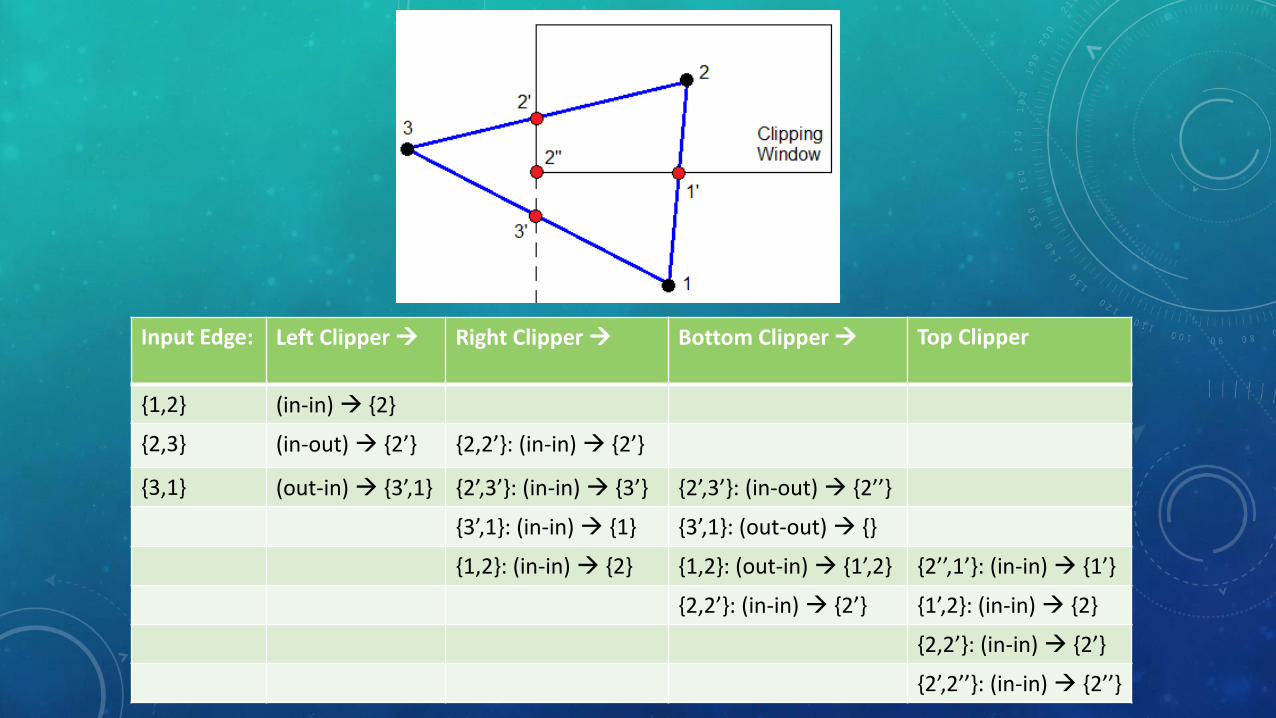
Input Edge: Left Clipper Right Clipper Bottom Clipper Top Clipper
{1,2} (in-in) {2}
{2,3} (in-out) {2’} {2,2’}: (in-in) {2’}
{3,1} (out-in) {3’,1} {2’,3’}: (in-in) {3’} {2’,3’}: (in-out) {2’’}
{3’,1}: (in-in) {1} {3’,1}: (out-out) {}
{1,2}: (in-in) {2} {1,2}: (out-in) {1’,2} {2’’,1’}: (in-in) {1’}
{2,2’}: (in-in) {2’} {1’,2}: (in-in) {2}
{2,2’}: (in-in) {2’}
{2’,2’’}: (in-in) {2’’}

PARALLEL EXECUTION
• As soon as one clipper outputs a pair of endpoints, it can pass it to the next clipper allows parallel execution of clippers

CONCAVE POLYGONS?
• If only one vertex list sent along last vertex linked with last vertex
• Can create extraneous lines if we try to process concave polygons
• Alternatives:
• Split polygon into convex polygons
• Check for multiple intersection points on each boundary split lists (non-trivial to do this, however)
• Use another algorithm

WEILER-ATHERTON POLYGON CLIPPING

INTRODUCTION
• Weiler-Atherton Polygon Clipping
• Works with both convex and concave polygons
• Also works with any shape clipping region
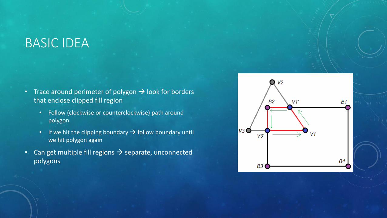
BASIC IDEA
• Trace around perimeter of polygon look for borders that enclose clipped fill region
• Follow (clockwise or counterclockwise) path around polygon
• If we hit the clipping boundary follow boundary until we hit polygon again
• Can get multiple fill regions separate, unconnected polygons

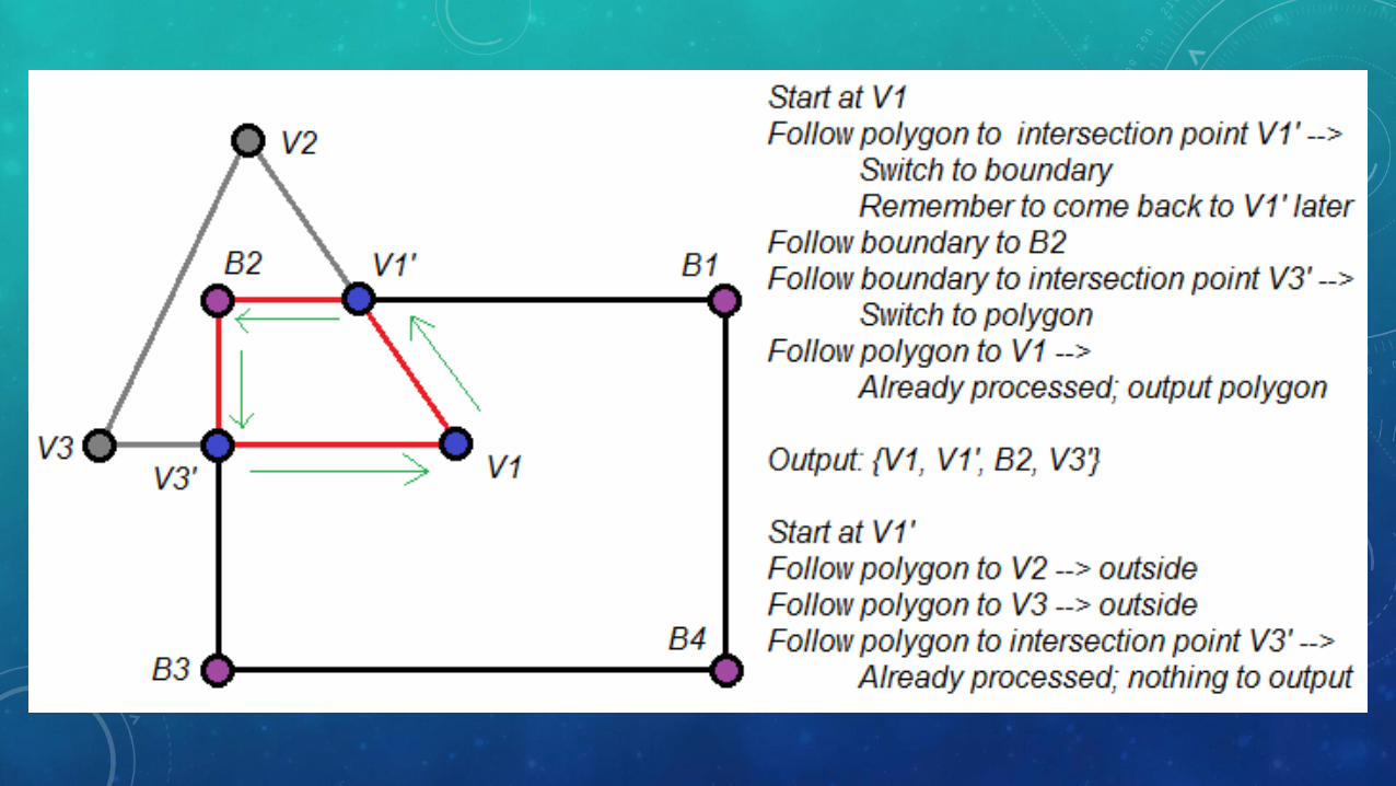
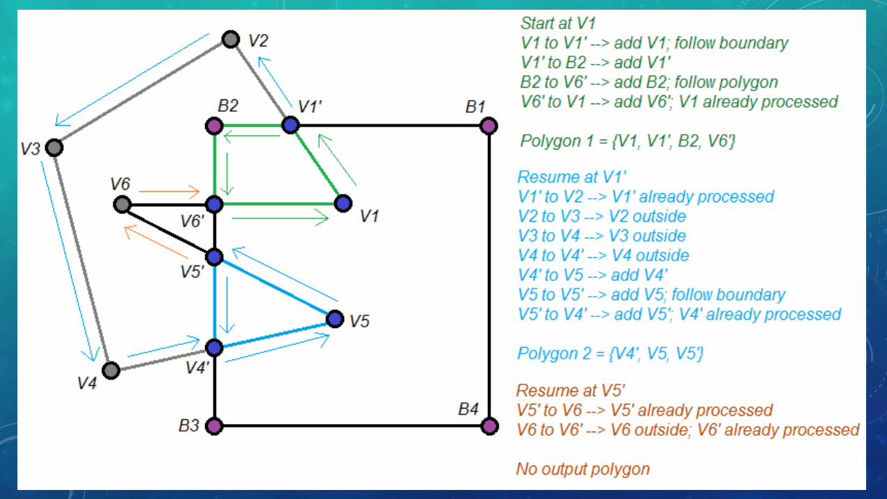
WEILER-ATHERTON ALGORITHM
• Start at first polygon vertex and follow POLYGON boundary; output vertex list = P = {}
• While any polygon vertices are “unprocessed”
• If current vertex unprocessed AND (current vertex inside OR on clipping boundary) add to P
• Go to next vertex
• If following POLYGON boundary:
• If next vertex = previously processed vertex
• Output P as new polygon, and clear P to start over current vertex = last INSIDE-OUTSIDE intersection point
• If next vertex = intersection point (INSIDE OUTSIDE)
• Start following CLIPPING boundary current vertex = next vertex
• Otherwise current vertex = next vertex
• If following CLIPPING boundary:
• If next vertex = intersection point (OUTSIDE INSIDE)
• Start following POLYGON boundary
• Current vertex = next vertex
3D CLIPPING ALGORITHMS
INTRODUCTION
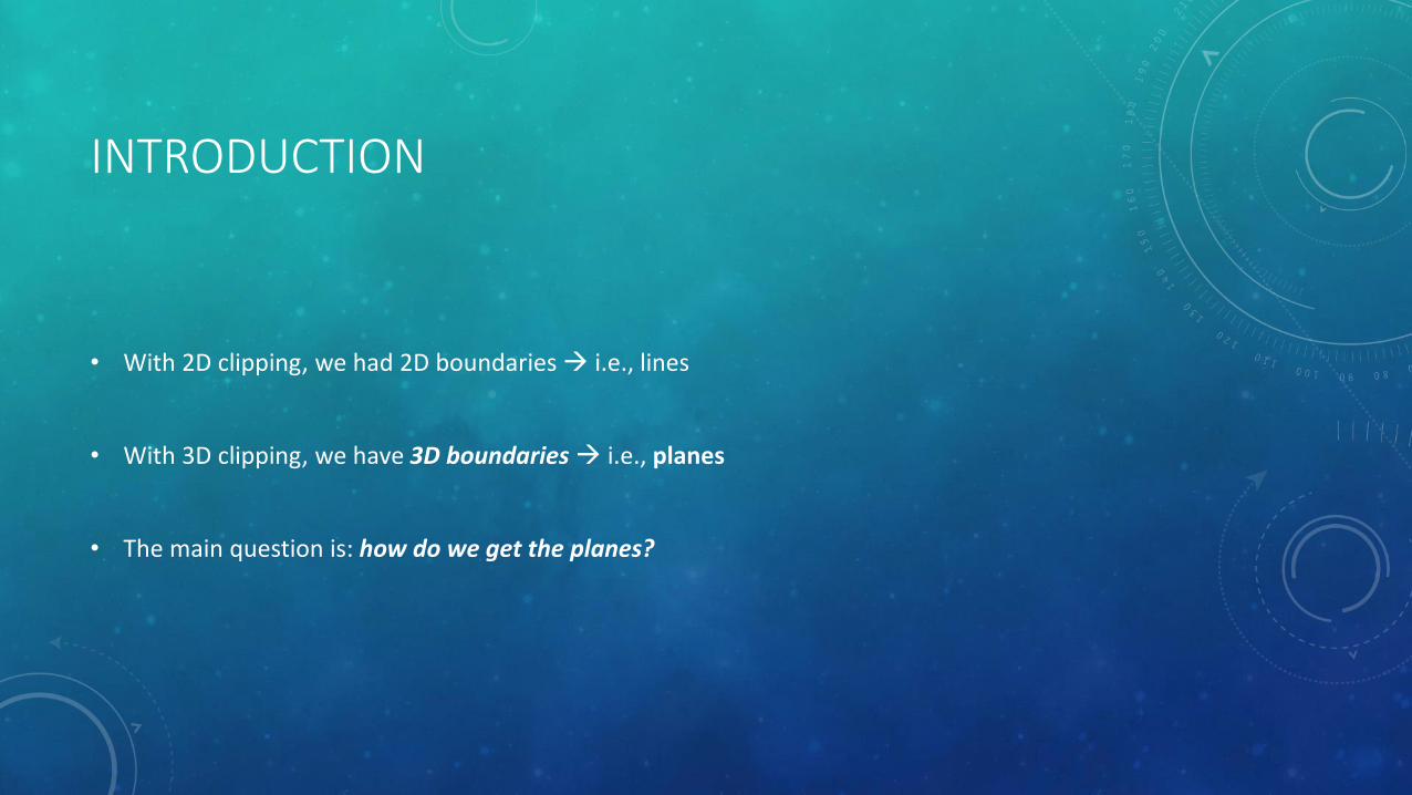
• With 2D clipping, we had 2D boundaries i.e., lines
• With 3D clipping, we have 3D boundaries i.e., planes
• The main question is: how do we get the planes?

GENERAL CLIPPING STRATEGIES
• You have one of three options:
• Option 1: Clip in CAMERA space (BEFORE projection)
• Planes boundaries of view volume in camera space
• Option 2: Clip in NORMALIZED DEVICE COORDINATES (AFTER projection)
• Planes
• PROBLEM: Issue with points BEHIND viewer!
• Option 3: Clip in 4D transformed space AFTER projection BUT BEFORE the homogeneous divide
• Planes 4D planes in homogeneous space!
111111 maxminmaxminmaxmin zzyyxx
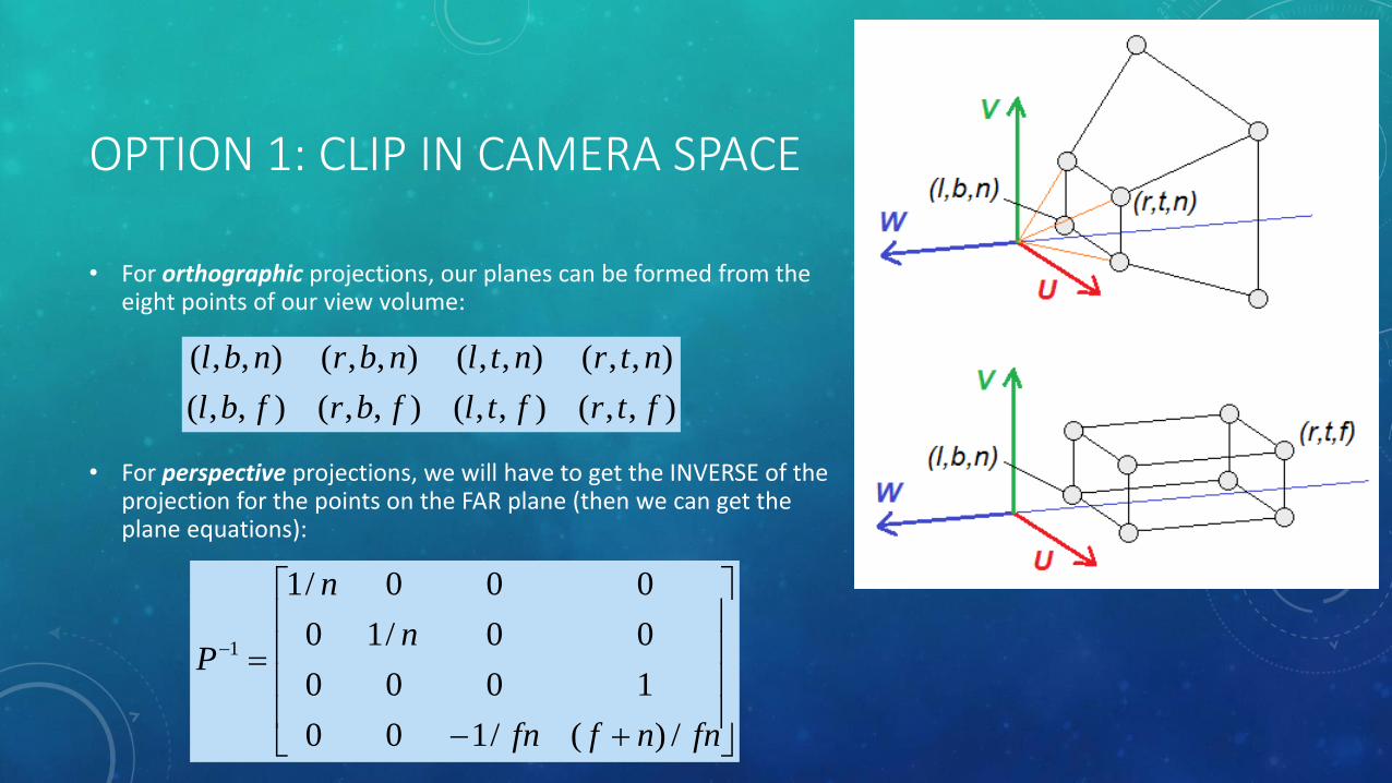
OPTION 1: CLIP IN CAMERA SPACE
• For orthographic projections, our planes can be formed from the eight points of our view volume:
• For perspective projections, we will have to get the INVERSE of the projection for the points on the FAR plane (then we can get the plane equations):
fnnffn
n
n
P
/)(/100
1000
00/10
000/1
1
),,(),,(),,(),,(
),,(),,(),,(),,(
ftrftlfbrfbl
ntrntlnbrnbl
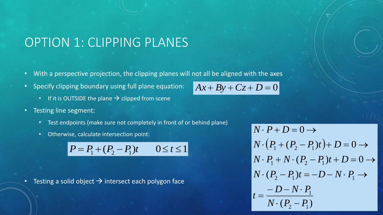
OPTION 1: CLIPPING PLANES
• With a perspective projection, the clipping planes will not all be aligned with the axes
• Specify clipping boundary using full plane equation:
• If it is OUTSIDE the plane clipped from scene
• Testing line segment:
• Test endpoints (make sure not completely in front of or behind plane)
• Otherwise, calculate intersection point:
• Testing a solid object intersect each polygon face
0 DCzByAx
10 )( 121 ttPPPP
)(
)(
0)(
0)(
0
12
1
112
121
121
PPN
PNDt
PNDtPPN
DtPPNPN
DtPPPN
DPN
OPTION 2: CLIP IN NORMALIZED DEVICE COORDINATES
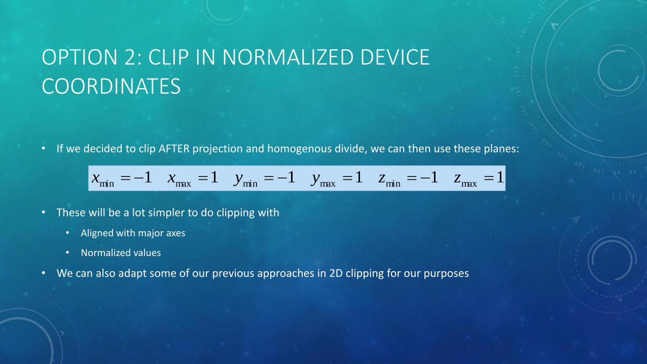
• If we decided to clip AFTER projection and homogenous divide, we can then use these planes:
• These will be a lot simpler to do clipping with
• Aligned with major axes
• Normalized values
• We can also adapt some of our previous approaches in 2D clipping for our purposes
111111 maxminmaxminmaxmin zzyyxx
3D REGION CODES (EXTENDING COHEN-SUTHERLAND)
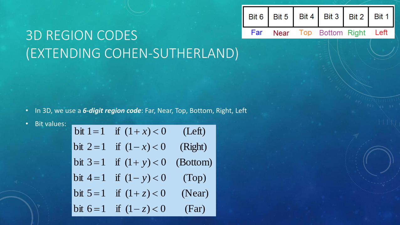
• In 3D, we use a 6-digit region code: Far, Near, Top, Bottom, Right, Left
• Bit values:
(Far)0)1( if1 6bit
(Near)0)1( if1 5bit
(Top)0)1( if1 4bit
(Bottom)0)1( if1 3bit
(Right)0)1( if1 2bit
(Left)0)(1 if1 1bit
z
z
y
y
x
x
3D POINT AND LINE CLIPPING
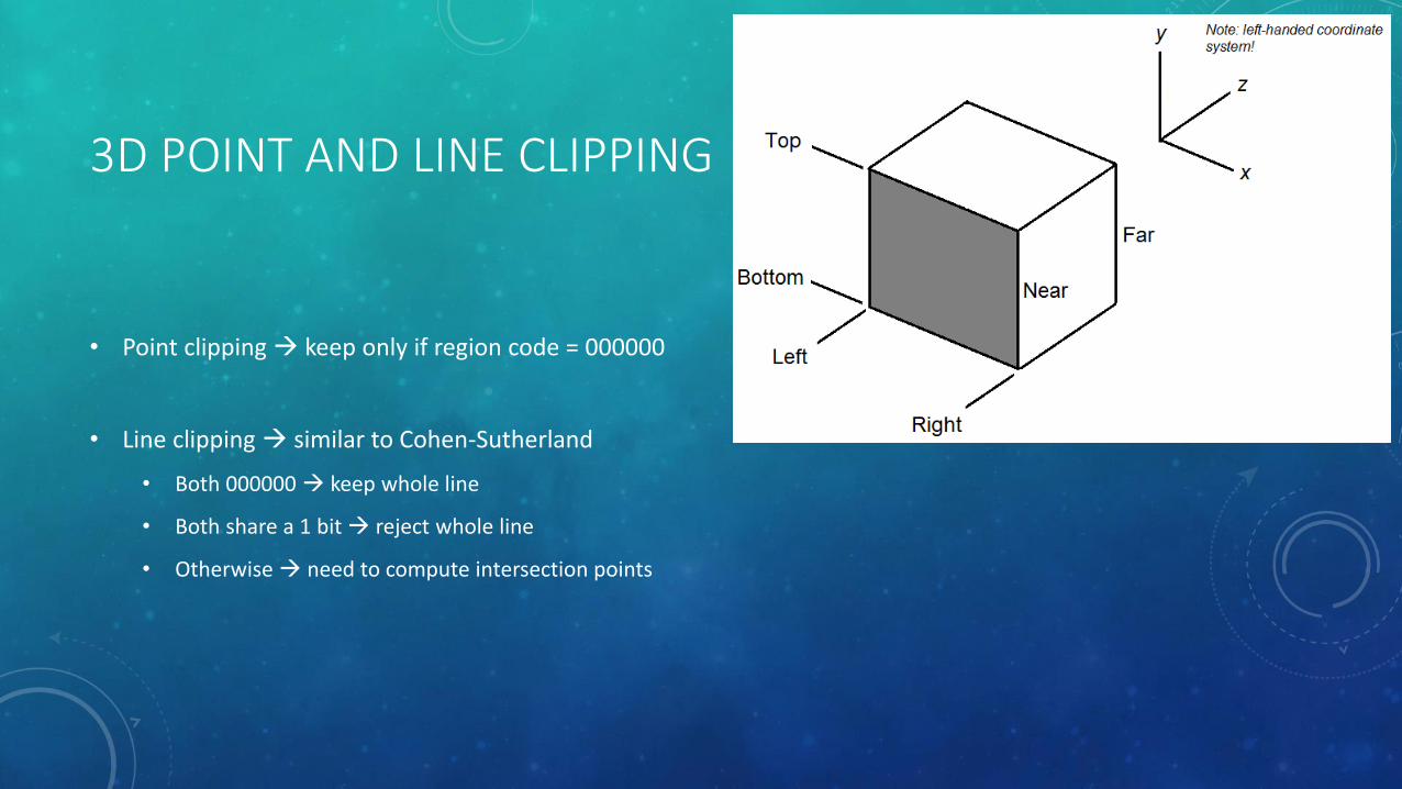
• Point clipping keep only if region code = 000000
• Line clipping similar to Cohen-Sutherland
• Both 000000 keep whole line
• Both share a 1 bit reject whole line
• Otherwise need to compute intersection points
3D LINE SEGMENTS AND PLANE BOUNDARIES
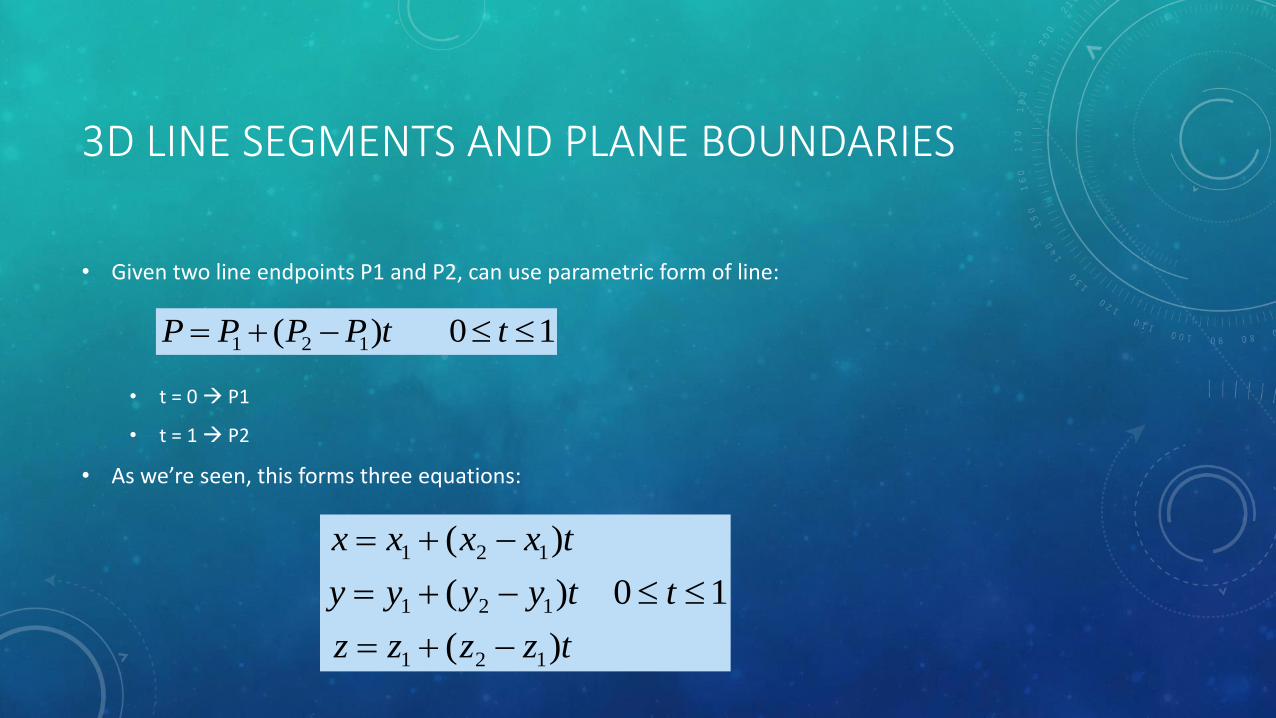
• Given two line endpoints P1 and P2, can use parametric form of line:
• t = 0 P1
• t = 1 P2
• As we’re seen, this forms three equations:
10 )( 121 ttPPPP
tzzzz
ttyyyy
txxxx
)(
10)(
)(
121
121
121
3D INTERSECTION POINTS
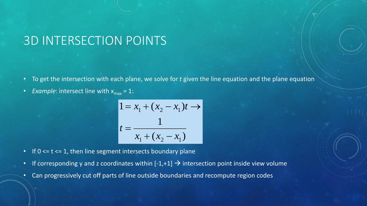
• To get the intersection with each plane, we solve for t given the line equation and the plane equation
• Example: intersect line with xmax = 1:
• If 0 <= t <= 1, then line segment intersects boundary plane
• If corresponding y and z coordinates within [-1,+1] intersection point inside view volume
• Can progressively cut off parts of line outside boundaries and recompute region codes
)(
1
)(1
121
121
xxxt
txxx
DEALING WITH 3D OBJECTS
• Can test polyhedron for trivial acceptance or rejection:
• Look at vertices
• Look at bounding sphere
• Etc.
• Otherwise, more complicated
• One approach:
• Divide surface into triangle strip
• Clip triangles using Sutherland-Hodgman on each of the six clipping planes
• Get output vertices of final strip
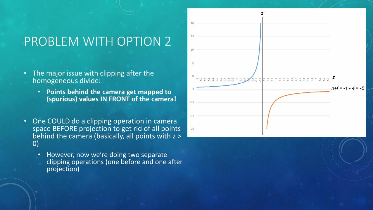
PROBLEM WITH OPTION 2
• The major issue with clipping after the homogeneous divide:
• Points behind the camera get mapped to (spurious) values IN FRONT of the camera!
• One COULD do a clipping operation in camera space BEFORE projection to get rid of all points behind the camera (basically, all points with z > 0)
• However, now we’re doing two separate clipping operations (one before and one after projection)
OPTION 3: CLIP BEFORE HOMOGENEOUS DIVIDE
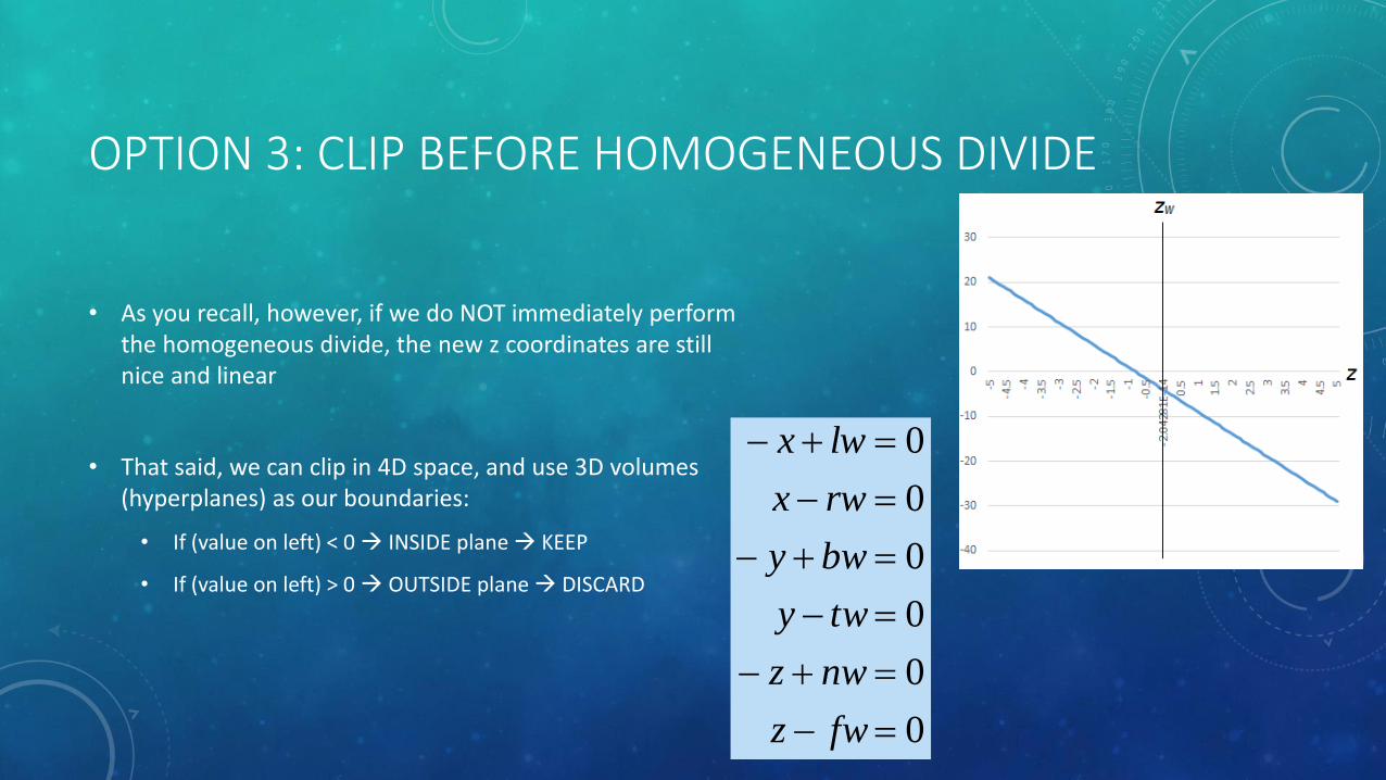
• As you recall, however, if we do NOT immediately perform the homogeneous divide, the new z coordinates are still nice and linear
• That said, we can clip in 4D space, and use 3D volumes (hyperplanes) as our boundaries:
• If (value on left) < 0 INSIDE plane KEEP
• If (value on left) > 0 OUTSIDE plane DISCARD
0
0
0
0
0
0
fwz
nwz
twy
bwy
rwx
lwx
OPTION 3: 4D SPACE?
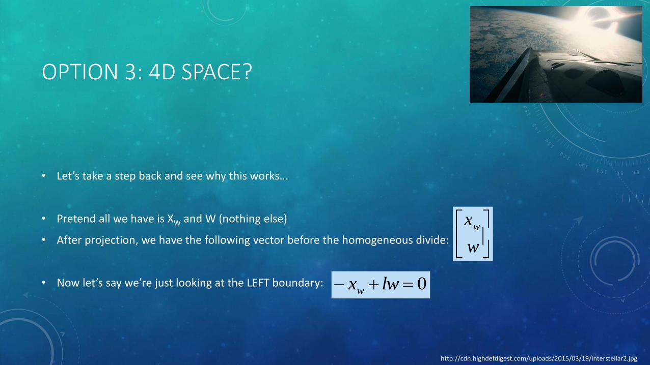
• Let’s take a step back and see why this works…
• Pretend all we have is XW and W (nothing else)
• After projection, we have the following vector before the homogeneous divide:
• Now let’s say we’re just looking at the LEFT boundary:
http://cdn.highdefdigest.com/uploads/2015/03/19/interstellar2.jpg
0 lwxw
w
xw
OPTION 3: 4D SPACE?
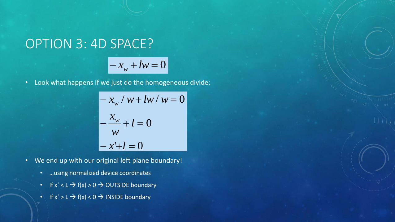
• Look what happens if we just do the homogeneous divide:
• We end up with our original left plane boundary!
• …using normalized device coordinates
• If x’ < L f(x) > 0 OUTSIDE boundary
• If x’ > L f(x) < 0 INSIDE boundary
0 lwxw
0'
0
0//
lx
lw
x
wlwwx
w
w

SCREEN MAPPING
SCREEN MAPPING
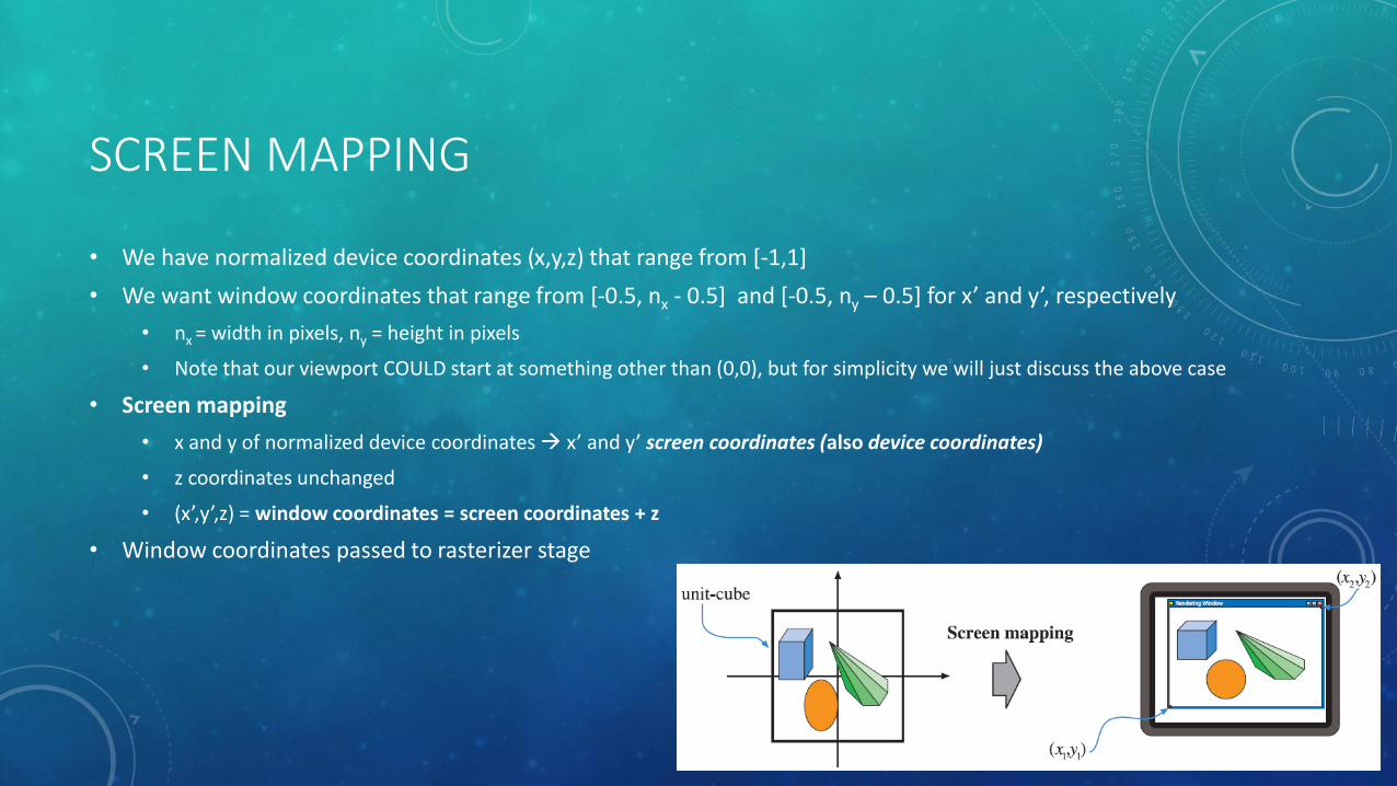
• We have normalized device coordinates (x,y,z) that range from [-1,1]
• We want window coordinates that range from [-0.5, nx - 0.5] and [-0.5, ny – 0.5] for x’ and y’, respectively
• nx = width in pixels, ny = height in pixels
• Note that our viewport COULD start at something other than (0,0), but for simplicity we will just discuss the above case
• Screen mapping
• x and y of normalized device coordinates x’ and y’ screen coordinates (also device coordinates)
• z coordinates unchanged
• (x’,y’,z) = window coordinates = screen coordinates + z
• Window coordinates passed to rasterizer stage
VIEWPORT MATRIX
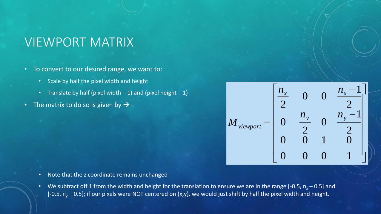
• To convert to our desired range, we want to:
• Scale by half the pixel width and height
• Translate by half (pixel width – 1) and (pixel height – 1)
• The matrix to do so is given by
• Note that the z coordinate remains unchanged
• We subtract off 1 from the width and height for the translation to ensure we are in the range [-0.5, nx – 0.5] and [-0.5, ny – 0.5]; if our pixels were NOT centered on (x,y), we would just shift by half the pixel width and height.
1000
01002
10
20
2
100
2
yy
xx
viewport
nn
nn
M