Embed Size (px)
Citation preview
Crystallisation of a simulated borosilicate high-level waste glass produced on a full-
scale vitrification line
Peter B. Rose a, David I. Woodward b, Michael I. Ojovan a, Neil C. Hyatt a, William
E. Lee c,*
a Immobilisation Science Laboratory, Department of Engineering Materials,
University of Sheffield, Sheffield S1 3JD, UK
b ITM Power plc, Sheffield Airport Business Park, Sheffield S9 1XU, UK
c Department of Materials, Imperial College London, London SW7 2AZ, UK
* Corresponding author. Tel.: +44 (0)20 7594 6733; fax: +44 (0)20 7594 6736. E-mail
address: [email protected] (W.E. Lee).
Abstract
A simulated (inactive) borosilicate high-level waste (HLW) glass was produced on a
full-scale vitrification line with composition simulating vitrified oxide fuel (UO2)
reprocessing waste. As-cast samples were compositionally homogeneous (Type I
microstructure) and/or compositionally inhomogeneous displaying compositional
‘banding’ and frequently containing ‘reprecipitated calcine’ (Type II microstructure).
Crystal phases identified in as-cast samples were: tetragonal RuO2, cubic Pd–Te alloy,
cubic (Cr,Fe,Ni,Ru)3O4, trigonal Na3Li(MoO4)2·6H2O, ostensibly cubic
Zr1−x−yCexGdyO2−0.5y and a lanthanoid (Nd,Gd,La,Ce) silicate. Zr1−x−yCexGdyO2−0.5y and
lanthanoid (Nd,Gd,La,Ce) silicate were found exclusively in the Type II
1
microstructure as component crystal phases of ‘reprecipitated calcine’. Heat treated
samples (simulating the retarded cooling experienced by actual (active) borosilicate
HLW glasses after pouring) displayed extensive crystallisation and cracking (Type A
microstructure) and/or ‘banded’ crystallisation (Type B microstructure) depending on
their parent (as-cast) microstructure (Type I and/or Type II respectively). Crystal
phases identified in heat treated samples were: tetragonal SiO2 (α-cristobalite),
tetragonal (Na,Sr,Nd,La)MoO4, cubic Ce1−x−yZrxGdyO2−0.5y, a Ni-rich phase, a
lanthanoid (Nd,Gd,La,Ce) silicate and orthorhombic LiNaZrSi6O15 (zektzerite). α-
cristobalite was found exclusively in the Type A microstructure, while lanthanoid
(Nd,Gd,La,Ce) silicate and zektzerite were only found in the Type B microstructure.
Potential host phases for HLW radionuclides are: Pd–Te alloy (107Pd and 79Se),
(Cr,Fe,Ni,Ru)3O4 (63Ni), Zr1−x−yCexGdyO2−0.5y (93Zr, Pu and U), both lanthanoid
(Nd,Gd,La,Ce) silicates (Am and Cm), (Na,Sr,Nd,La)MoO4 (90Sr, Am and Cm),
Ce1−x−yZrxGdyO2−0.5y (93Zr, Pu and U), the Ni-rich phase (63Ni) and zektzerite (93Zr,
126Sn and U). Cracking in samples was attributed to thermal expansion mismatch
between the borosilicate HLW glass matrix and RuO2, cristobalite (both α and β),
(Na,Sr,Nd,La)MoO4 and zektzerite on cooling. There was also a contribution from the
cristobalite α–β phase transition.
PACS: 64.70.dg; 81.05.Kf; 28.41.Kw; 81.40.Gh; 81.05.Pj
1. Introduction
In the UK, spent nuclear fuel is reprocessed to recover Pu and U with the
remaining solution being regarded as waste. The liquid waste arising from
2
reprocessing is termed high-level waste (HLW) due to the level of radioactivity and
heat it generates. Liquid HLW is currently immobilised by vitrification in a mixed
alkali borosilicate glass matrix. This provides a material suitable for storage and
eventual disposal, envisioned to be in an underground repository located within a
stable geological formation [1–7].
During vitrification some HLW components have limited solubility in the
borosilicate glass melt, typically platinoids (Ru, Pd and Rh), high oxidation state
cations (e.g. Mo6+, S6+ and Cr6+) and refractory oxides (e.g. Al2O3 and Cr2O3). These
components of limited solubility can form crystal phases and/or an immiscible liquid
(generally termed ‘yellow phase’) during glass melting [1–7]. Due to the radiogenic
heat produced by decaying radionuclides the glass will experience retarded cooling
from its melting temperature [1,3]. This retarded cooling can lead to further crystal
phases precipitating in the glass (as can multiple glass pours into the same
storage/disposal canister [8]), often nucleated and grown upon crystal phases formed
during glass melting [7]. If immiscible ‘yellow phase’ forms during glass melting and
persists until glass pouring it will crystallise on cooling [7].
Borosilicate HLW glasses incorporating crystal phases and/or ‘yellow phase’
can be described as glass composite materials (GCMs) as they are neither fully
amorphous nor fully crystalline, although they are predominantly amorphous.
Describing them as glass-ceramics would be incorrect as they are not crystallised by a
controlled heat treatment to produce a desired microstructure and crystal phase(s).
The component elements of GCMs can be chemically incorporated into the glass
structure and/or physically encapsulated by the glass matrix (if incorporated into
crystal phases and/or ‘yellow phase’). The product of immobilising waste in a suitable
matrix is a wasteform [5,6].
3
The crystallisation (devitrification) of borosilicate HLW glasses and melts can
have a variety of consequences. HLW radionuclides can partition into crystal phases
and/or the glass matrix, depending on the crystal phase(s) formed [7]. The aqueous
durability of crystal phases reported in borosilicate HLW glasses varies from high
(such as spinels [9,10] and powellite-structured molybdates [7,11–13]) to low (for
example the water-soluble portion of ‘yellow phase’ [3,12–23]). The effect of
crystallisation on the aqueous durability of a wasteform can range from beneficial
[1,17] to detrimental [3,24–27], being a cumulative effect if multiple crystal phases
are present. During glass melting molten ‘yellow phase’ can corrode glass melters
[14,20,22,23,28–34] and increase the volatilisation of some component species
[23,35–37]. Crystal phases in glass melts can sediment to the melter floor
[2,20,25,38–42], forming a ‘sludge’ layer of higher density, electrical conductivity
and viscosity, which can cause pouring difficulties [20,38–43] and short circuit
submerged electrodes (if present) [2,38–41,44–46]. The thermal expansion
coefficients (TECs) of crystal phases may differ from those of the surrounding glass
matrix, which can generate stress and may eventually lead to cracking of the
wasteform on cooling [7]. Crystal phase formation may alter the TEC of the
surrounding glass matrix by modifying its chemical composition [7]. Cracking of the
glass matrix and/or crystal phases can also occur if the crystal phases undergo phase
transitions on cooling [7]. Preferential aqueous corrosion at glass–crystal interfaces
may occur [7,10,47–50] due to chemical composition gradients and/or stress caused
by TEC mismatch and/or crystal phase transitions [48–50]. This is particularly
undesirable since HLW radionuclides tend to concentrate at these interfaces [10,47].
Crystal phases present in actual (active) borosilicate HLW glasses may become
metamict (amorphous) due to irradiation, thereby increasing in volume which can
4
generate stress and may eventually lead to cracking [3,51–53]. Cracking of a
wasteform can reduce its aqueous durability because its surface area increases [44].
Crystal phases incorporating HLW radionuclides may be detrimentally affected by
nuclear transmutations (e.g. 90Sr to 90Y to 90Zr) [7]. Ideally, crystal phases formed in
borosilicate HLW glasses would have excellent aqueous durabilities, preferentially
incorporate HLW radionuclides and be homogeneously distributed within a glass
matrix of higher aqueous durability than the parent glass (due to the crystal phases
preferentially incorporating elements detrimental to the aqueous durability of the glass
matrix). In addition, the crystal phases would be radiation tolerant, nuclear
transmutation tolerant, not undergo phase transitions on cooling and have TECs equal
to, or larger than, the surrounding glass matrix [7].
This paper reports studies conducted on a simulated borosilicate HLW glass
produced during inactive commissioning of a full-scale vitrification line at Sellafield,
Cumbria, UK. This research aimed to identify the crystal phases present in as-cast
samples, as well as determining which radionuclides may preferentially partition to
them in actual borosilicate HLW glasses. It also aimed to identify the crystal phases
formed after heat treating as-cast samples (simulating the retarded cooling
experienced by radiogenically heated HLW glasses after pouring) and to determine
which radionuclides may preferentially partition to these crystal phases in actual
borosilicate HLW glasses.
2. Experimental
The simulated borosilicate HLW glass used in this work was supplied by
Nexia Solutions Ltd and is termed Oxide glass. This trial composition simulates
5
vitrified oxide fuel (UO2) reprocessing waste and was produced during inactive
commissioning of a full-scale vitrification line at Sellafield, Cumbria, UK. The
vitrification process at Sellafield is described elsewhere [1,2,7]. Received as-cast
samples were from multiple pours and had not been annealed.
Heat treatment of as-cast samples was conducted in a temperature calibrated
Lenton 1500 W muffle furnace with an air atmosphere. Samples of approximately 2
cm3 were cut from as-cast samples using a Struers Accutom-5 diamond saw and then
placed on a bed of calcined alumina in a mullite tray. These were then held at 690 °C
for 70 h before a 1 h anneal at 500 °C with heating and cooling rates of 5 °C min−1.
Any calcined alumina adhering to heat treated samples was removed.
Chemical analysis of Oxide glass samples was accomplished by combined X-
ray fluorescence spectrometry (XRF) and direct current plasma atomic emission
spectrometry (DCP-AES). An ARL 9400 Sequential XRF analysed Oxide glass
samples for all elements heavier than boron using a Cu-filtered Rh X-ray source, a gas
flow proportional counter employing P-10 gas (90% argon, 10% methane), a
scintillation counter and was operated with a helium atmosphere. Three different
Oxide glass samples were crushed in a steel percussion mortar, ground with an agate
pestle and mortar and then sieved to <75 μm before analysis. UniQuant version 4.44
software (a universal, standardless analytical program) calculated the normalised
chemical composition of each sample once their respective DCP-AES data (for B2O3
and Li2O) were entered.
An SMI III DCP-AES utilising argon plasma analysed Oxide glass samples to
determine wt% values for B2O3 and Li2O after calibration with a multielement
solution standard. Each of the three different Oxide glass samples prepared for XRF
(<75 μm powders) had a sample placed in a Teflon container for microwave-assisted
6
acid digestion with HF–HNO3 solution in a CEM MSP 1000 microwave. Digested
samples were analysed alongside a digested multicomponent borosilicate glass
standard (National Institute of Standards and Technology (NIST) standard reference
material 1412) to ensure accuracy of the compositional data. After the B2O3 and Li2O
data from each sample had been added to its respective XRF data in UniQuant the
three normalised chemical compositions were calculated, with the mean chemical
composition being reported.
Archimedes' principle was used to calculate the unannealed as-cast sample
density in deionised water at 21 °C. Three different as-cast samples were tested with
the mean density being reported.
For differential thermal analysis (DTA) a Perkin Elmer DTA 7 running Perkin
Elmer PYRIS version 5.00.02 thermal analysis software was used to determine the
glass transition temperature (Tg) of Oxide glass by onset. The as-cast glass was
crushed in a steel percussion mortar and then ground with an agate pestle and mortar
before sieving to <75 μm. Both the sample and alumina reference material were
placed in identical alumina crucibles and heated to 1000 °C at 5 °C min−1 in a static
air atmosphere.
Viscosity measurements of Oxide glass at high temperature were undertaken
using a heat-shielded Brookfield DV-II+ viscometer. Samples were brought to
temperature in a Pt crucible with a hemispherical base before insertion of the spindle.
Melts were then allowed to equilibrate at temperature before measurements were
taken.
Powder X-ray diffraction (XRD) of as-cast and heat treated samples was
performed on Philips PW1710 and Siemens D500 diffractometers, both employing
Ni-filtered Cu Kα (K-L2,3) radiation and operating at 40 kV and 30 mA. Both
7
machines operated in reflection mode, scanning from 10° to 80° 2θ at 0.1° min−1 in
0.01° steps. Samples were crushed in a steel percussion mortar, ground with an agate
pestle and mortar, and sieved to <75 μm before being placed in aluminium sample
holders for loading into the machines. XRD traces were peak-matched to crystal
phases detailed in the International Centre for Diffraction Data (ICDD) database using
STOE WinXPOW version 1.06 software, after first being converted for use in WinXPOW
by Traces version 4.2 software followed by WinFit! version 1.12 software.
Scanning electron microscope (SEM) analysis of as-cast and heat treated
samples was conducted with a JEOL JSM 6400 operating at an accelerating voltage of
20 kV and equipped with a Link Analytical ISIS energy dispersive X-ray
spectroscopy (EDX) system with beryllium window. Secondary electron (SE) and
backscattered electron (BE) images were collected from samples, along with EDX
spectra. Samples were sectioned to approximately 1 cm3 using a Struers Accutom-5
diamond saw before mounting them in cold-setting epoxy resin (Struers EpoFix)
under vacuum. Mounted samples were then ground with sequentially finer grit SiC
papers (from 120 to 1200) and water before polishing to a finish of 1 μm with
diamond pastes. Polished samples were partially painted with Acheson electrodag
1415M silver paint and then carbon coated using an Edwards “Speedivac” model
12E6/1598 coating unit before analysis.
Transmission electron microscope (TEM) investigation of as-cast and heat
treated samples employed a Philips EM 420T(D) fitted with a Link Analytical eXL
EDX system (with ATW2) and an FEI Tecnai 20 equipped with an EDAX Genesis
EDX system (with SUTW). The microscopes operated with accelerating voltages of
120 kV and 200 kV respectively and both employed double-tilt sample holders.
Bright-field (BF) micrographs and selected-area electron diffraction patterns, as well
8
as EDX spectra, were collected from samples. Samples were sectioned to
approximately 500 μm thickness using a Struers Accutom-5 diamond saw before
being mounted on a Gatan 623 disk grinder using heat-sensitive resin. Both sides of
samples were subsequently ground with sequentially finer grit SiC papers (from 120
to 1200) and water to a final section thickness of approximately 30 μm. Sections were
then cleaned of resin using acetone before 3.05 mm diameter copper rings with a 1
mm diameter aperture were attached using Devcon 5-minute epoxy glue. A Gatan
Dual Ion Mill (DuoMill) model 600 operating with an accelerating voltage of 6 kV at
a combined gun current of 0.6 mA subsequently milled the samples at an incidence
angle of 15° (2 h) followed by 10° (to perforation). Milled samples were then carbon
coated using an Edwards “Speedivac” model 12E6/1598 coating unit before analysis.
Obtained electron diffraction patterns were indexed using simulated electron
diffraction patterns produced with CaRIne Crystallography version 3.1 software. The
space group, lattice parameters and atomic coordinates of crystal phases were needed
for their simulation in CaRIne and were obtained from the Inorganic Crystal Structure
Database (ICSD).
3. Results and discussion
3.1. Chemical, physical and thermal analysis
The chemical composition of Oxide glass is presented in Table 1, from which
its waste loading (WL) and molar mass (M) were calculated (Table 2). The measured
density (ρ) of unannealed as-cast Oxide glass allowed its unannealed molar volume
(Vm) to be calculated using Vm = M/ρ (Table 2). The glass transition temperature (Tg)
9
of Oxide glass is also given in Table 2. Oxide glass melts displayed non-Newtonian
viscosity behaviour.
Non-Newtonian viscosity behaviour in borosilicate HLW glass melts has been
observed previously and is thought to be caused by the presence of platinoid phases
[12,19,40,41,54].
3.2. Phase and microstructural analysis
3.2.1. As-cast samples
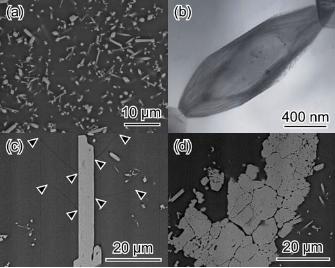
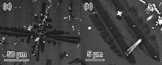
Some as-cast samples had compositionally homogeneous glass matrices (Fig.
1(a)) termed Type I microstructure. Other as-cast samples had compositionally
inhomogeneous glass matrices (Figs. 1(b) and 2(a)) termed Type II microstructure.
The Type II microstructure displayed compositional ‘banding’ and frequently
contained ‘reprecipitated calcine’. Occasionally as-cast samples displayed both Type I
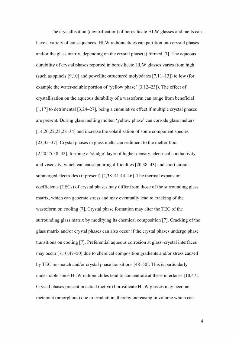
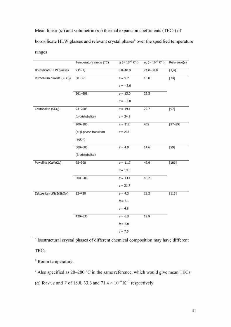
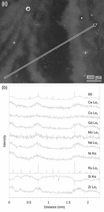
and Type II microstructures. An EDX line scan (Fig. 2) revealed the bright ‘bands’
(indicating higher average atomic number in that region) in the Type II microstructure
were enriched in Ce, Cs, Gd, Mo, Nd, Ni and Zr (simulated HLW components) while
being depleted in Si, relative to the bulk glass composition.
Type I microstructure indicates the as-cast samples had sufficient reaction
time between the base glass frit and the simulated HLW calcine in the glass melter
before pouring to form a homogeneous glass. Type II microstructure indicates that the
base glass frit and simulated HLW calcine had insufficient reaction time in the glass
melter before pouring to form a homogeneous glass. Less than 1 h residence time in
the glass melter is suggested by the presence of ‘reprecipitated calcine’ and bubbles
[1,20,55], and also compositional ‘banding’ [20,56]. Wasteform aqueous durability
10
will be detrimentally affected by this compositional ‘banding’, the ‘bands’ enriched in
simulated HLW components being of lower aqueous durability than the ‘bands’
enriched in base glass [56]. The internal microstructure of ‘reprecipitated calcine’
consisted of two crystal phases, Zr1−x−yCexGdyO2−0.5y and lanthanoid (Nd,Gd,La,Ce)
silicate, consistent with previous reports [20,55]. These crystal phases will have
precipitated from the glass melt on cooling due to local supersaturation of their
component elements [55]. ‘Reprecipitated calcine’ in a borosilicate HLW glass will
be preferentially leached, lowering the overall aqueous durability of the wasteform
[57].
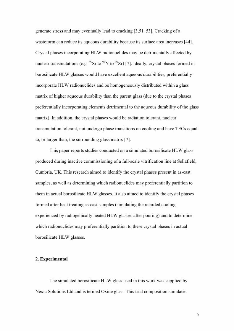
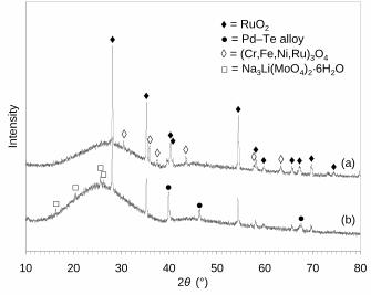
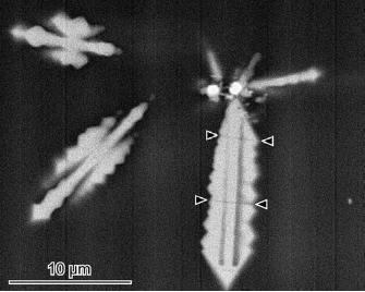
3.2.1.1. RuO2 RuO2 (rutile crystal structure, tetragonal crystal system, space group
P42/mnm) was identified in as-cast samples by XRD (labelled ♦ in Fig. 3(a) and (b))
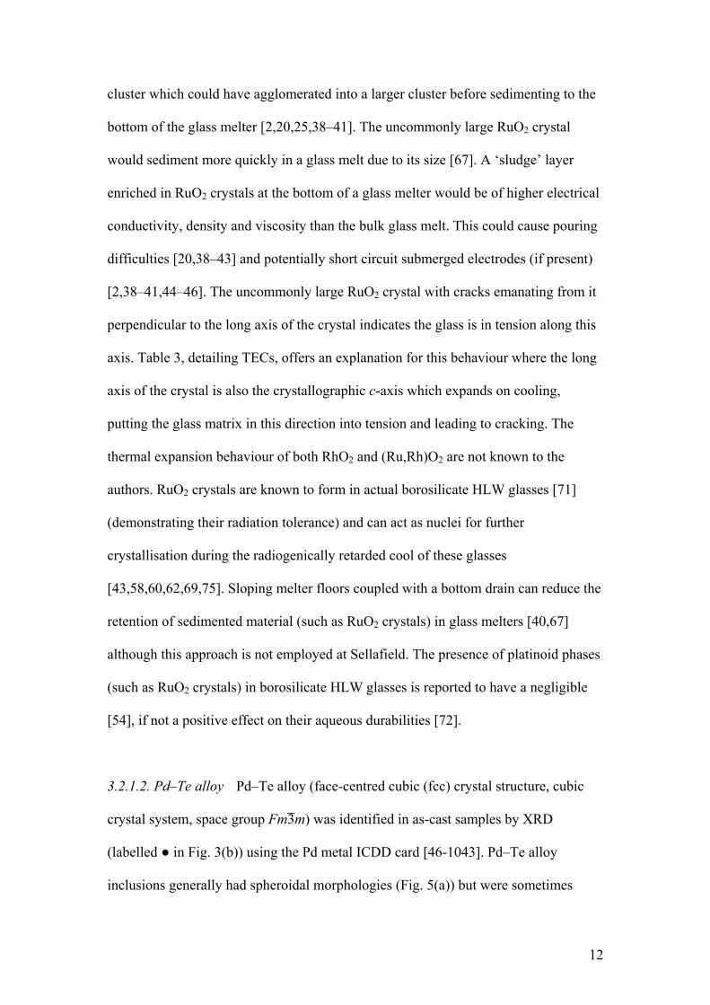
using ICDD card [40-1290]. RuO2 crystals had acicular morphologies (Fig. 4(a)–(c)),
while a globular Ru inclusion (Fig. 4(d)) was proposed to be Ru metal. A RuO2
crystal contacting other RuO2 crystals is shown in Fig. 4(b), while an uncommonly
large RuO2 crystal had cracks emanating from it perpendicular to the long axis of the
crystal (arrowed in Fig. 4(c)). An EDX line scan (Fig. 2) revealed RuO2 crystals/Ru
metal inclusions were randomly distributed throughout the glass matrix of even a
compositionally inhomogeneous as-cast sample (Type II microstructure). RuO2
crystals were found in both Type I and Type II microstructures.
RuO2 crystals are common in borosilicate HLW glasses [1,8,12,19,25,39–
41,43,46,54,56,58–68], often having acicular morphologies [1,12,39,40,46,54,69,70]
and incorporating Rh if present, forming (Ru,Rh)O2 crystals [3,39–41,67,69–72]. Ru
metal inclusions in borosilicate HLW glasses have been reported previously
[41,66,73]. The RuO2 crystal contacting neighbouring RuO2 crystals was part of a
11
cluster which could have agglomerated into a larger cluster before sedimenting to the
bottom of the glass melter [2,20,25,38–41]. The uncommonly large RuO2 crystal
would sediment more quickly in a glass melt due to its size [67]. A ‘sludge’ layer
enriched in RuO2 crystals at the bottom of a glass melter would be of higher electrical
conductivity, density and viscosity than the bulk glass melt. This could cause pouring
difficulties [20,38–43] and potentially short circuit submerged electrodes (if present)
[2,38–41,44–46]. The uncommonly large RuO2 crystal with cracks emanating from it
perpendicular to the long axis of the crystal indicates the glass is in tension along this
axis. Table 3, detailing TECs, offers an explanation for this behaviour where the long
axis of the crystal is also the crystallographic c-axis which expands on cooling,
putting the glass matrix in this direction into tension and leading to cracking. The
thermal expansion behaviour of both RhO2 and (Ru,Rh)O2 are not known to the
authors. RuO2 crystals are known to form in actual borosilicate HLW glasses [71]
(demonstrating their radiation tolerance) and can act as nuclei for further
crystallisation during the radiogenically retarded cool of these glasses
[43,58,60,62,69,75]. Sloping melter floors coupled with a bottom drain can reduce the
retention of sedimented material (such as RuO2 crystals) in glass melters [40,67]
although this approach is not employed at Sellafield. The presence of platinoid phases
(such as RuO2 crystals) in borosilicate HLW glasses is reported to have a negligible
[54], if not a positive effect on their aqueous durabilities [72].
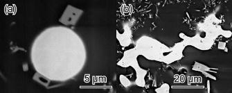
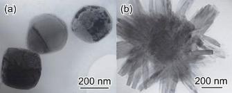
3.2.1.2. Pd–Te alloy Pd–Te alloy (face-centred cubic (fcc) crystal structure, cubic
crystal system, space group Fm3̄m) was identified in as-cast samples by XRD
(labelled ● in Fig. 3(b)) using the Pd metal ICDD card [46-1043]. Pd–Te alloy
inclusions generally had spheroidal morphologies (Fig. 5(a)) but were sometimes
12
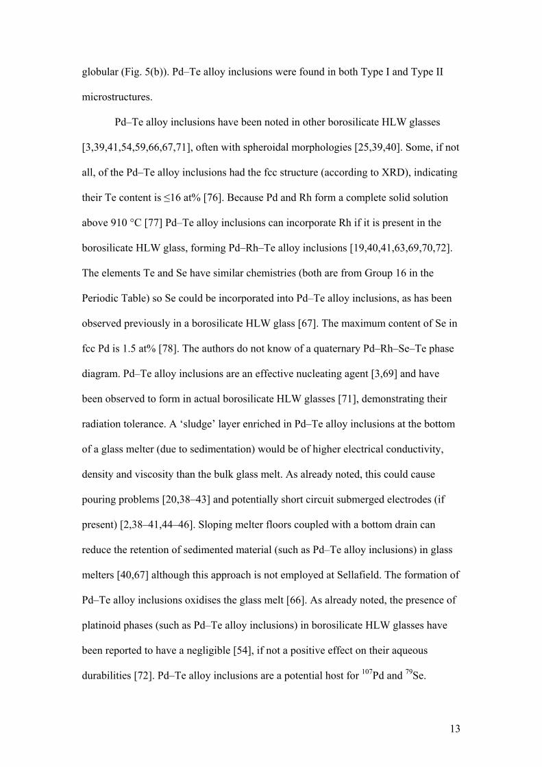
globular (Fig. 5(b)). Pd–Te alloy inclusions were found in both Type I and Type II
microstructures.
Pd–Te alloy inclusions have been noted in other borosilicate HLW glasses
[3,39,41,54,59,66,67,71], often with spheroidal morphologies [25,39,40]. Some, if not
all, of the Pd–Te alloy inclusions had the fcc structure (according to XRD), indicating
their Te content is ≤16 at% [76]. Because Pd and Rh form a complete solid solution
above 910 °C [77] Pd–Te alloy inclusions can incorporate Rh if it is present in the
borosilicate HLW glass, forming Pd–Rh–Te alloy inclusions [19,40,41,63,69,70,72].
The elements Te and Se have similar chemistries (both are from Group 16 in the
Periodic Table) so Se could be incorporated into Pd–Te alloy inclusions, as has been
observed previously in a borosilicate HLW glass [67]. The maximum content of Se in
fcc Pd is 1.5 at% [78]. The authors do not know of a quaternary Pd–Rh–Se–Te phase
diagram. Pd–Te alloy inclusions are an effective nucleating agent [3,69] and have
been observed to form in actual borosilicate HLW glasses [71], demonstrating their
radiation tolerance. A ‘sludge’ layer enriched in Pd–Te alloy inclusions at the bottom
of a glass melter (due to sedimentation) would be of higher electrical conductivity,
density and viscosity than the bulk glass melt. As already noted, this could cause
pouring problems [20,38–43] and potentially short circuit submerged electrodes (if
present) [2,38–41,44–46]. Sloping melter floors coupled with a bottom drain can
reduce the retention of sedimented material (such as Pd–Te alloy inclusions) in glass
melters [40,67] although this approach is not employed at Sellafield. The formation of
Pd–Te alloy inclusions oxidises the glass melt [66]. As already noted, the presence of
platinoid phases (such as Pd–Te alloy inclusions) in borosilicate HLW glasses have
been reported to have a negligible [54], if not a positive effect on their aqueous
durabilities [72]. Pd–Te alloy inclusions are a potential host for 107Pd and 79Se.
13
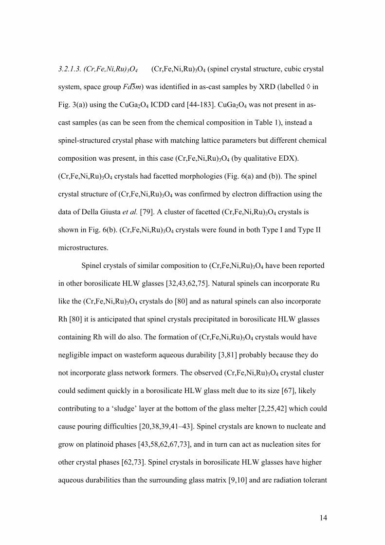
3.2.1.3. (Cr,Fe,Ni,Ru)3O4 (Cr,Fe,Ni,Ru)3O4 (spinel crystal structure, cubic crystal
system, space group Fd3̄m) was identified in as-cast samples by XRD (labelled ◊ in
Fig. 3(a)) using the CuGa2O4 ICDD card [44-183]. CuGa2O4 was not present in as-
cast samples (as can be seen from the chemical composition in Table 1), instead a
spinel-structured crystal phase with matching lattice parameters but different chemical
composition was present, in this case (Cr,Fe,Ni,Ru)3O4 (by qualitative EDX).
(Cr,Fe,Ni,Ru)3O4 crystals had facetted morphologies (Fig. 6(a) and (b)). The spinel
crystal structure of (Cr,Fe,Ni,Ru)3O4 was confirmed by electron diffraction using the
data of Della Giusta et al. [79]. A cluster of facetted (Cr,Fe,Ni,Ru)3O4 crystals is
shown in Fig. 6(b). (Cr,Fe,Ni,Ru)3O4 crystals were found in both Type I and Type II
microstructures.
Spinel crystals of similar composition to (Cr,Fe,Ni,Ru)3O4 have been reported
in other borosilicate HLW glasses [32,43,62,75]. Natural spinels can incorporate Ru
like the (Cr,Fe,Ni,Ru)3O4 crystals do [80] and as natural spinels can also incorporate
Rh [80] it is anticipated that spinel crystals precipitated in borosilicate HLW glasses
containing Rh will do also. The formation of (Cr,Fe,Ni,Ru)3O4 crystals would have
negligible impact on wasteform aqueous durability [3,81] probably because they do
not incorporate glass network formers. The observed (Cr,Fe,Ni,Ru)3O4 crystal cluster
could sediment quickly in a borosilicate HLW glass melt due to its size [67], likely
contributing to a ‘sludge’ layer at the bottom of the glass melter [2,25,42] which could
cause pouring difficulties [20,38,39,41–43]. Spinel crystals are known to nucleate and
grow on platinoid phases [43,58,62,67,73], and in turn can act as nucleation sites for
other crystal phases [62,73]. Spinel crystals in borosilicate HLW glasses have higher
aqueous durabilities than the surrounding glass matrix [9,10] and are radiation tolerant
14
[82], as evidenced by their formation in actual borosilicate HLW glasses [71,81].
(Cr,Fe,Ni,Ru)3O4 crystals are a potential host for 63Ni (an activation product).
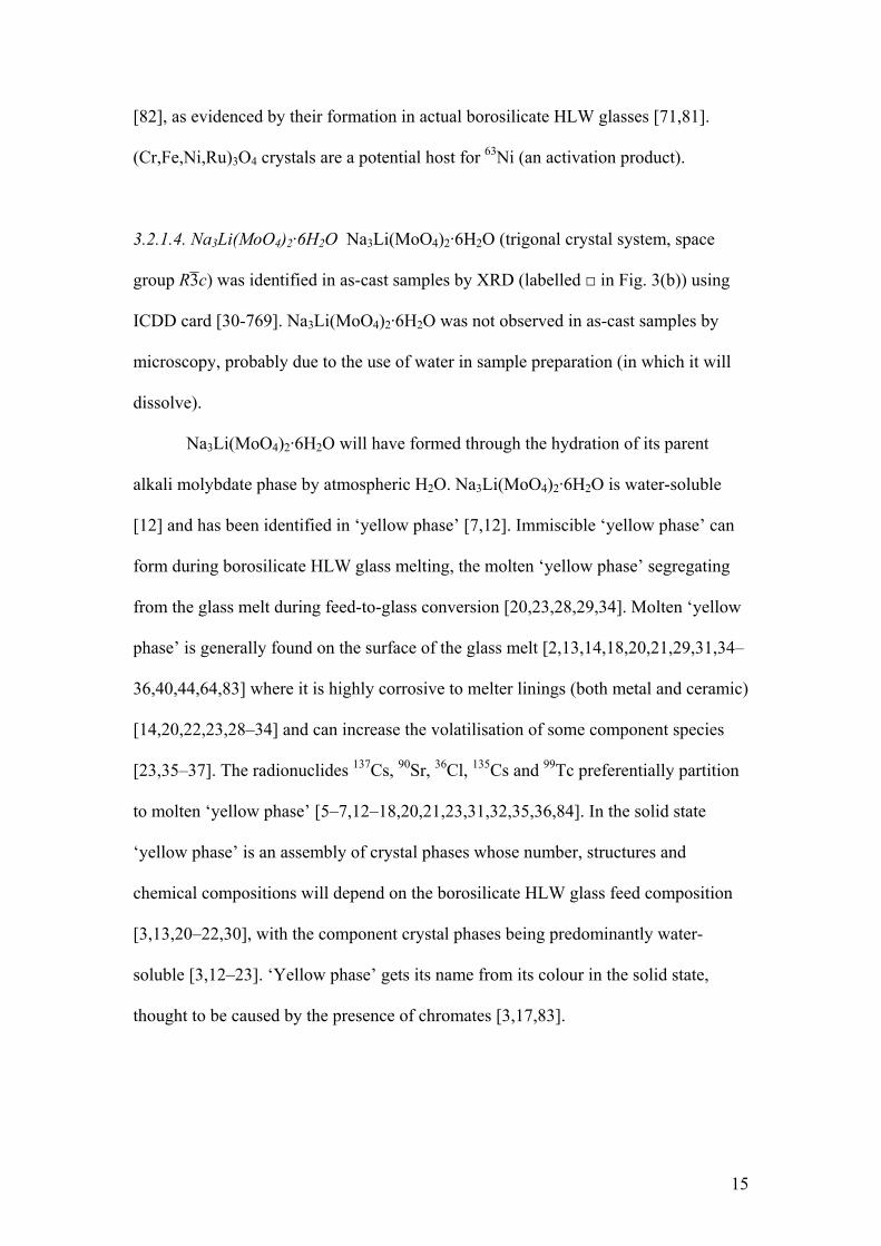
3.2.1.4. Na3Li(MoO4)2·6H2O Na3Li(MoO4)2·6H2O (trigonal crystal system, space
group R3̄c) was identified in as-cast samples by XRD (labelled □ in Fig. 3(b)) using
ICDD card [30-769]. Na3Li(MoO4)2·6H2O was not observed in as-cast samples by
microscopy, probably due to the use of water in sample preparation (in which it will
dissolve).
Na3Li(MoO4)2·6H2O will have formed through the hydration of its parent
alkali molybdate phase by atmospheric H2O. Na3Li(MoO4)2·6H2O is water-soluble
[12] and has been identified in ‘yellow phase’ [7,12]. Immiscible ‘yellow phase’ can
form during borosilicate HLW glass melting, the molten ‘yellow phase’ segregating
from the glass melt during feed-to-glass conversion [20,23,28,29,34]. Molten ‘yellow
phase’ is generally found on the surface of the glass melt [2,13,14,18,20,21,29,31,34–
36,40,44,64,83] where it is highly corrosive to melter linings (both metal and ceramic)
[14,20,22,23,28–34] and can increase the volatilisation of some component species
[23,35–37]. The radionuclides 137Cs, 90Sr, 36Cl, 135Cs and 99Tc preferentially partition
to molten ‘yellow phase’ [5–7,12–18,20,21,23,31,32,35,36,84]. In the solid state
‘yellow phase’ is an assembly of crystal phases whose number, structures and
chemical compositions will depend on the borosilicate HLW glass feed composition
[3,13,20–22,30], with the component crystal phases being predominantly water-
soluble [3,12–23]. ‘Yellow phase’ gets its name from its colour in the solid state,
thought to be caused by the presence of chromates [3,17,83].
15
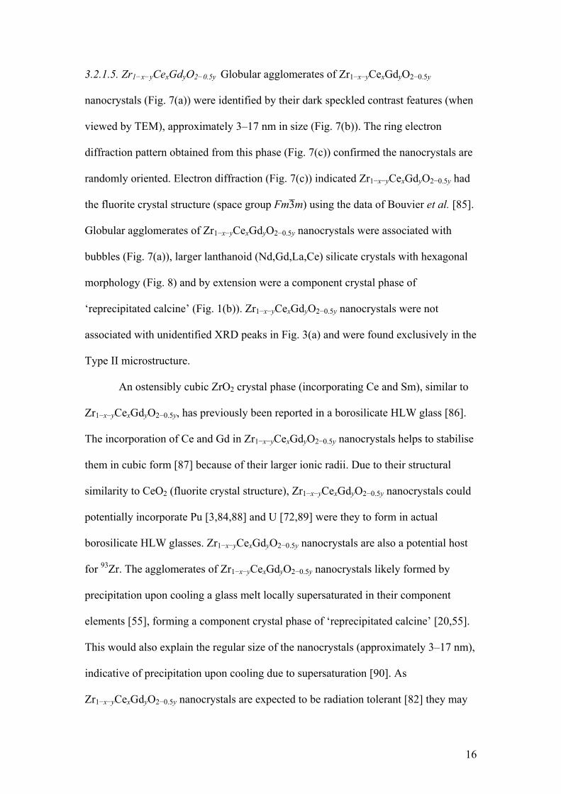
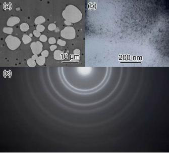
3.2.1.5. Zr1−x−yCexGdyO2−0.5y Globular agglomerates of Zr1−x−yCexGdyO2−0.5y
nanocrystals (Fig. 7(a)) were identified by their dark speckled contrast features (when
viewed by TEM), approximately 3–17 nm in size (Fig. 7(b)). The ring electron
diffraction pattern obtained from this phase (Fig. 7(c)) confirmed the nanocrystals are
randomly oriented. Electron diffraction (Fig. 7(c)) indicated Zr1−x−yCexGdyO2−0.5y had
the fluorite crystal structure (space group Fm3̄m) using the data of Bouvier et al. [85].
Globular agglomerates of Zr1−x−yCexGdyO2−0.5y nanocrystals were associated with
bubbles (Fig. 7(a)), larger lanthanoid (Nd,Gd,La,Ce) silicate crystals with hexagonal
morphology (Fig. 8) and by extension were a component crystal phase of
‘reprecipitated calcine’ (Fig. 1(b)). Zr1−x−yCexGdyO2−0.5y nanocrystals were not
associated with unidentified XRD peaks in Fig. 3(a) and were found exclusively in the
Type II microstructure.
An ostensibly cubic ZrO2 crystal phase (incorporating Ce and Sm), similar to
Zr1−x−yCexGdyO2−0.5y, has previously been reported in a borosilicate HLW glass [86].
The incorporation of Ce and Gd in Zr1−x−yCexGdyO2−0.5y nanocrystals helps to stabilise
them in cubic form [87] because of their larger ionic radii. Due to their structural
similarity to CeO2 (fluorite crystal structure), Zr1−x−yCexGdyO2−0.5y nanocrystals could
potentially incorporate Pu [3,84,88] and U [72,89] were they to form in actual
borosilicate HLW glasses. Zr1−x−yCexGdyO2−0.5y nanocrystals are also a potential host
for 93Zr. The agglomerates of Zr1−x−yCexGdyO2−0.5y nanocrystals likely formed by
precipitation upon cooling a glass melt locally supersaturated in their component
elements [55], forming a component crystal phase of ‘reprecipitated calcine’ [20,55].
This would also explain the regular size of the nanocrystals (approximately 3–17 nm),
indicative of precipitation upon cooling due to supersaturation [90]. As
Zr1−x−yCexGdyO2−0.5y nanocrystals are expected to be radiation tolerant [82] they may
16
form in actual borosilicate HLW glasses. A problem for agglomerates of
Zr1−x−yCexGdyO2−0.5y nanocrystals may be preferential corrosion between the
nanocrystals during aqueous leaching [10].
The crystal structure of ZrO2 doped with CeO2 and Gd2O3 (analogous to the
Zr1−x−yCexGdyO2−0.5y nanocrystals) can vary from tetragonal (t, space group P42/nmc)
to cubic (c, space group Fm3̄m) with decreasing levels of ZrO2. Between these two
forms lie metastable t′ (space group P42/nmc, axial ratio c/a >1) and then pseudocubic
t″ (an intermediate form between t′ and c, space group P42/nmc, axial ratio c/a = 1)
[87]. XRD and electron diffraction are usually not sensitive enough to the oxygen
displacements associated with these different forms to differentiate between them
(especially with the peak broadening associated with nanocrystalline phases) so
Raman spectroscopy is generally used [87,91]. Unfortunately the Zr1−x−yCexGdyO2−0.5y
nanocrystals contain Gd3+ cations so oxygen vacancies in the crystals will reduce the
effectiveness of Raman spectroscopy [87]. Therefore, while we have no direct
evidence, the Zr1−x−yCexGdyO2−0.5y nanocrystals are expected to be cubic (c) or
pseudocubic (t″) as nanocrystals of this size (≤17 nm) help stabilise CeO2-doped ZrO2
as t″/c [91].
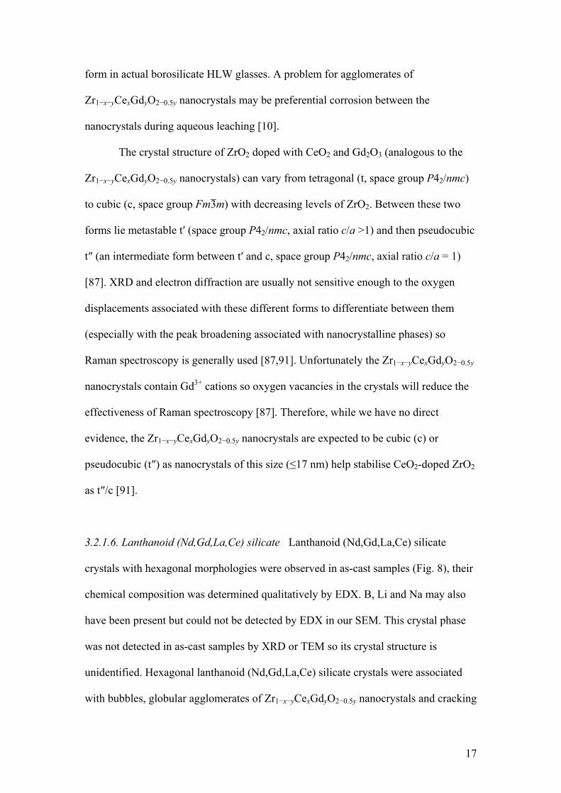
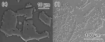
3.2.1.6. Lanthanoid (Nd,Gd,La,Ce) silicate Lanthanoid (Nd,Gd,La,Ce) silicate
crystals with hexagonal morphologies were observed in as-cast samples (Fig. 8), their
chemical composition was determined qualitatively by EDX. B, Li and Na may also
have been present but could not be detected by EDX in our SEM. This crystal phase
was not detected in as-cast samples by XRD or TEM so its crystal structure is
unidentified. Hexagonal lanthanoid (Nd,Gd,La,Ce) silicate crystals were associated
with bubbles, globular agglomerates of Zr1−x−yCexGdyO2−0.5y nanocrystals and cracking
17
(Fig. 8), and by extension were a component crystal phase of ‘reprecipitated calcine’
(Fig. 1(b)). Lanthanoid (Nd,Gd,La,Ce) silicate crystals were likely associated with
unidentified XRD peaks in Fig. 3(a) and were found exclusively in the Type II
microstructure.
Lanthanoid (Nd,Gd,La,Ce) silicate crystals likely formed by precipitation
upon cooling a glass melt locally supersaturated in their component elements [55],
forming a component crystal phase of ‘reprecipitated calcine’ [20,55]. As lanthanoid
(Nd,Gd,La,Ce) silicate crystals were associated with cracking their thermal expansion
behaviour is probably different from that of the surrounding glass matrix.
Furthermore, lanthanoid (Nd,Gd,La,Ce) silicate crystals are a potential host for Am
and Cm as both are present in the +3 oxidation state in borosilicate HLW glasses [51]
and have similar ionic radii to Nd [92].
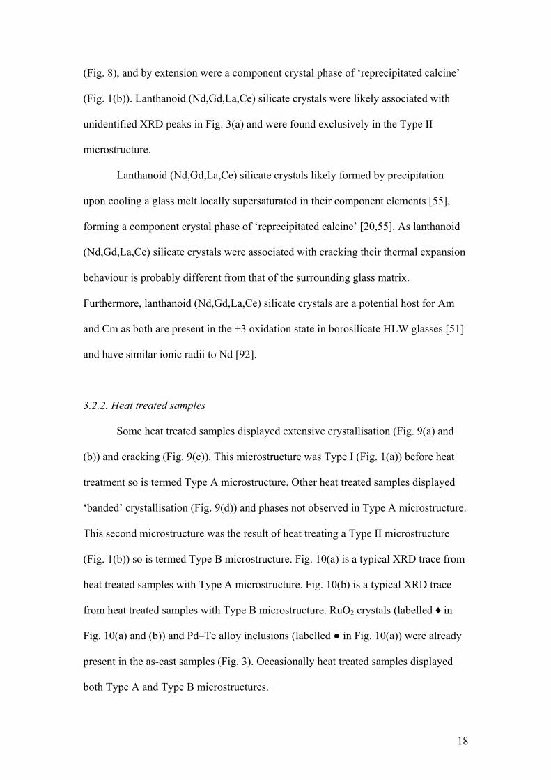
3.2.2. Heat treated samples
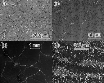
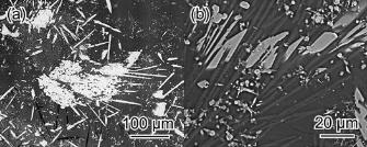
Some heat treated samples displayed extensive crystallisation (Fig. 9(a) and
(b)) and cracking (Fig. 9(c)). This microstructure was Type I (Fig. 1(a)) before heat
treatment so is termed Type A microstructure. Other heat treated samples displayed
‘banded’ crystallisation (Fig. 9(d)) and phases not observed in Type A microstructure.
This second microstructure was the result of heat treating a Type II microstructure
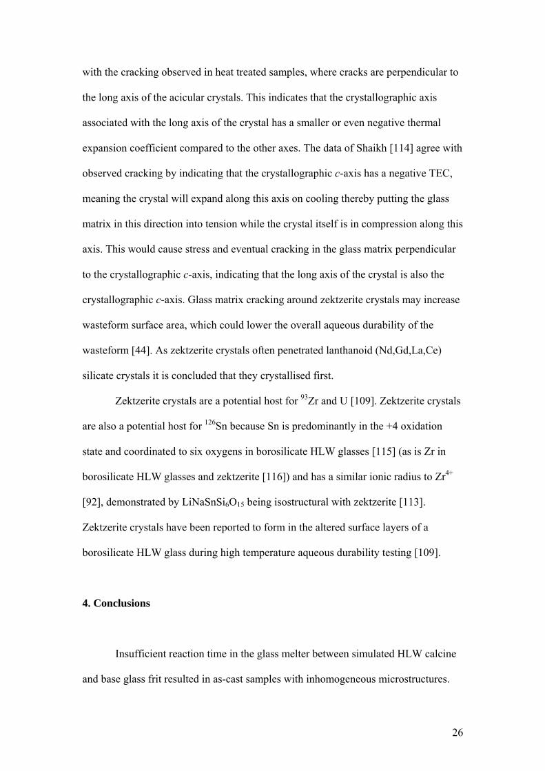
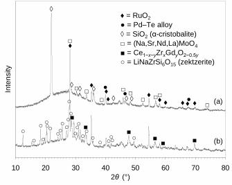
(Fig. 1(b)) so is termed Type B microstructure. Fig. 10(a) is a typical XRD trace from
heat treated samples with Type A microstructure. Fig. 10(b) is a typical XRD trace
from heat treated samples with Type B microstructure. RuO2 crystals (labelled ♦ in
Fig. 10(a) and (b)) and Pd–Te alloy inclusions (labelled ● in Fig. 10(a)) were already
present in the as-cast samples (Fig. 3). Occasionally heat treated samples displayed
both Type A and Type B microstructures.
18
Cracking seen in the Type A microstructure may be detrimental to wasteform
aqueous durability due to the potential increase in its surface area [44]. The ‘bands’ of
crystallisation displayed by the Type B microstructure formed from the ‘bands’
enriched in simulated HLW components in the parent (Type II) microstructure.
Minimal cracking in the Type B microstructure indicates little thermal expansion
mismatch between the glass matrix and encapsulated crystal phases. This negligible
potential increase in wasteform surface area is not expected to detrimentally affect
wasteform aqueous durability.
As a point of interest, acicular Ni- and Te-rich crystals of unidentified
composition (such as alloy, oxide or telluride) were observed protruding from the
surface of heat treated samples with Type B microstructure.
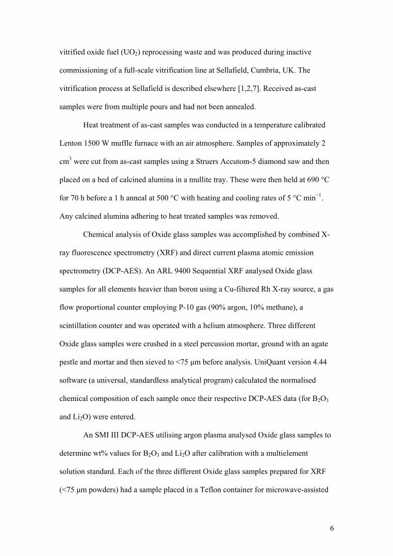
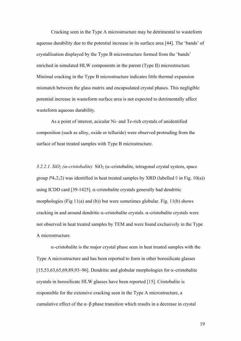
3.2.2.1. SiO2 (α-cristobalite) SiO2 (α-cristobalite, tetragonal crystal system, space
group P41212) was identified in heat treated samples by XRD (labelled ◊ in Fig. 10(a))
using ICDD card [39-1425]. α-cristobalite crystals generally had dendritic
morphologies (Fig 11(a) and (b)) but were sometimes globular. Fig. 11(b) shows
cracking in and around dendritic α-cristobalite crystals. α-cristobalite crystals were
not observed in heat treated samples by TEM and were found exclusively in the Type
A microstructure.
α-cristobalite is the major crystal phase seen in heat treated samples with the
Type A microstructure and has been reported to form in other borosilicate glasses
[15,53,63,65,69,89,93–96]. Dendritic and globular morphologies for α-cristobalite
crystals in borosilicate HLW glasses have been reported [15]. Cristobalite is
responsible for the extensive cracking seen in the Type A microstructure, a
cumulative effect of the α–β phase transition which results in a decrease in crystal
19
volume on cooling [65,93] and also TEC mismatch (for both α- and β-cristobalite)
with the surrounding glass matrix [95]. Table 3 shows that as the borosilicate HLW
glass cools β-cristobalite contracts more slowly than the surrounding glass matrix
putting the glass matrix in tension and causing its cracking. As the α–β phase
transition region is passed there is a volume decrease in the cristobalite which will
cause internal cracking as the crystal is physically anchored to the surrounding glass
matrix by its dendritic morphology. This internal cracking and voiding will continue
as the crystal cools to room temperature due to the faster contraction of α-cristobalite
compared to the surrounding glass matrix. The formation of cristobalite crystals
would be detrimental to wasteform aqueous durability as their precipitation removes
SiO2 from the surrounding glass matrix [7,49,63,69,93,96], resulting in a glass of
lower aqueous durability than the parent glass, especially around the crystals [69].
Glass matrix cracking around α-cristobalite crystals may increase wasteform surface
area, which could lower overall aqueous durability [44]. α-cristobalite crystals may
not be encountered in actual borosilicate HLW glasses as they are electron beam
sensitive [100] and therefore would not form in an environment with excessive β and
γ radiation [101], let alone α radiation. This explains why no α-cristobalite crystals
were observed by TEM. However, as the amorphous phase separation (APS) of a
borosilicate HLW glass has been observed prior to cristobalite crystallisation [65] and
APS of alkali borosilicate glasses is enhanced by electron irradiation [101], the
formation of a vitreous silica phase would have much the same effect on wasteform
aqueous durability as cristobalite formation [50,94]. As Al2O3 additions can inhibit
cristobalite crystallisation in alkali borosilicate glasses [95] and there is little Al2O3 in
Oxide glass it is suggested that increasing the amount of Al2O3 in Oxide glass may
inhibit cristobalite formation. Al2O3 additions to Oxide glass would also be beneficial
20
as they have been shown to suppress APS in sodium borosilicate glasses [50] and can
also improve the aqueous durability of borosilicate HLW glasses [2,3,102–104].
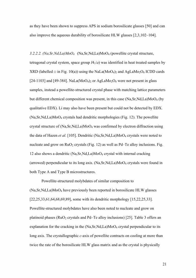
3.2.2.2. (Na,Sr,Nd,La)MoO4 (Na,Sr,Nd,La)MoO4 (powellite crystal structure,
tetragonal crystal system, space group I41/a) was identified in heat treated samples by
XRD (labelled □ in Fig. 10(a)) using the NaLa(MoO4)2 and AgLaMo2O8 ICDD cards
[24-1103] and [49-384]. NaLa(MoO4)2 or AgLaMo2O8 were not present in glass
samples, instead a powellite-structured crystal phase with matching lattice parameters
but different chemical composition was present, in this case (Na,Sr,Nd,La)MoO4 (by
qualitative EDX). Li may also have been present but could not be detected by EDX.
(Na,Sr,Nd,La)MoO4 crystals had dendritic morphologies (Fig. 12). The powellite
crystal structure of (Na,Sr,Nd,La)MoO4 was confirmed by electron diffraction using
the data of Hazen et al. [105]. Dendritic (Na,Sr,Nd,La)MoO4 crystals were noted to
nucleate and grow on RuO2 crystals (Fig. 12) as well as Pd–Te alloy inclusions. Fig.
12 also shows a dendritic (Na,Sr,Nd,La)MoO4 crystal with internal cracking
(arrowed) perpendicular to its long axis. (Na,Sr,Nd,La)MoO4 crystals were found in
both Type A and Type B microstructures.
Powellite-structured molybdates of similar composition to
(Na,Sr,Nd,La)MoO4 have previously been reported in borosilicate HLW glasses
[22,25,33,61,64,68,69,89], some with its dendritic morphology [15,22,25,33].
Powellite-structured molybdates have also been noted to nucleate and grow on
platinoid phases (RuO2 crystals and Pd–Te alloy inclusions) [25]. Table 3 offers an
explanation for the cracking in the (Na,Sr,Nd,La)MoO4 crystal perpendicular to its
long axis. The crystallographic c-axis of powellite contracts on cooling at more than
twice the rate of the borosilicate HLW glass matrix and as the crystal is physically
21
anchored to the glass matrix by its dendritic morphology this will lead to tension
along the c-axis, eventually causing cracking in the crystal perpendicular to this
tension, indicating that the long axis of the crystal is also the crystallographic c-axis.
Powellite-structured molybdates have been reported to form in actual borosilicate
HLW glasses [71], demonstrating their radiation tolerance. Powellite-structured
molybdates are water-insoluble [7,11–13], their crystallisation reducing the leach rate
of elements incorporated by them [26] and slightly improving the overall wasteform
aqueous durability [54]. (Na,Sr,Nd,La)MoO4 crystals are a potential host for 90Sr, as
well as for Am and Cm [107] as both are in the +3 oxidation state in borosilicate
HLW glasses [51] and have similar ionic radii to Nd [92]. Powellite-structured
molybdates have been reported to form in the altered surface layers of borosilicate
HLW glasses during high temperature and/or long-term aqueous durability tests [107–
109].
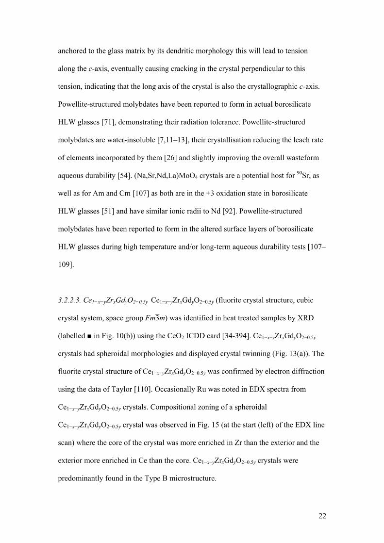
3.2.2.3. Ce1−x−yZrxGdyO2−0.5y Ce1−x−yZrxGdyO2−0.5y (fluorite crystal structure, cubic
crystal system, space group Fm3̄m) was identified in heat treated samples by XRD
(labelled ■ in Fig. 10(b)) using the CeO2 ICDD card [34-394]. Ce1−x−yZrxGdyO2−0.5y
crystals had spheroidal morphologies and displayed crystal twinning (Fig. 13(a)). The
fluorite crystal structure of Ce1−x−yZrxGdyO2−0.5y was confirmed by electron diffraction
using the data of Taylor [110]. Occasionally Ru was noted in EDX spectra from
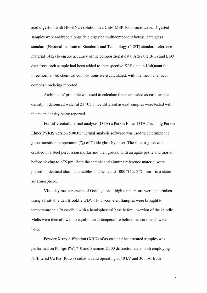
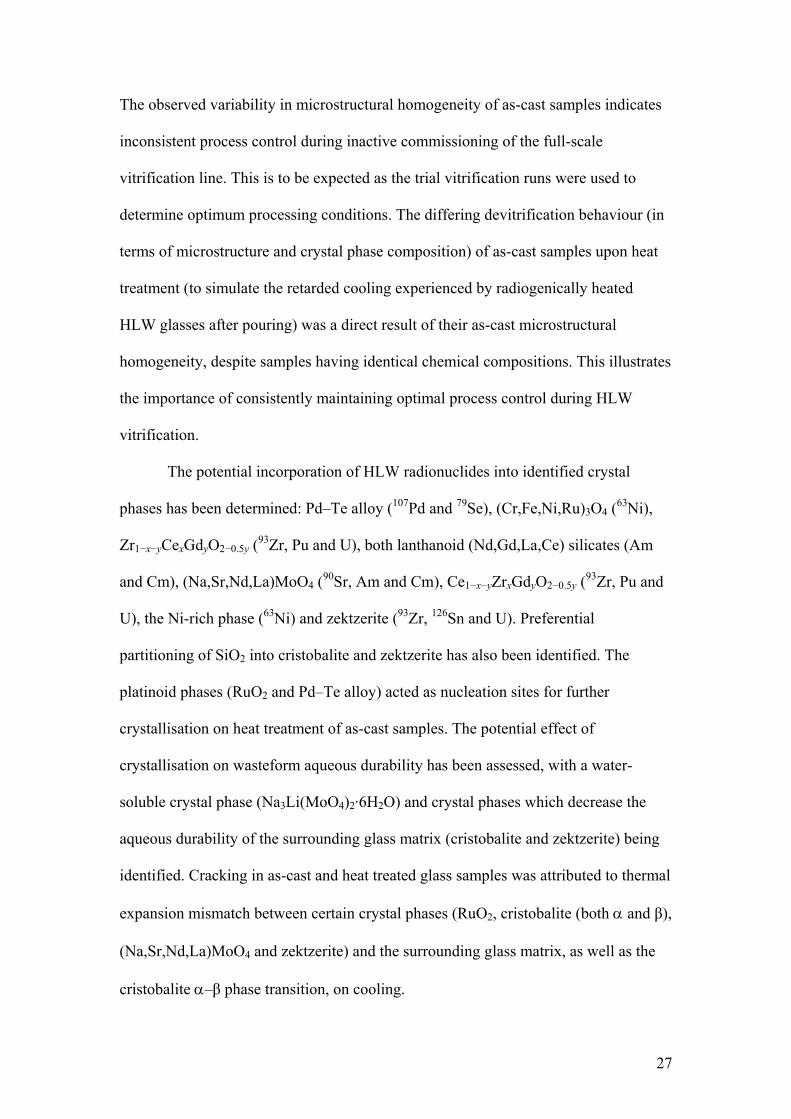
Ce1−x−yZrxGdyO2−0.5y crystals. Compositional zoning of a spheroidal
Ce1−x−yZrxGdyO2−0.5y crystal was observed in Fig. 15 (at the start (left) of the EDX line
scan) where the core of the crystal was more enriched in Zr than the exterior and the
exterior more enriched in Ce than the core. Ce1−x−yZrxGdyO2−0.5y crystals were
predominantly found in the Type B microstructure.
22
Ce1−x−yZrxGdyO2−0.5y crystals are similar to crystal phases previously reported
in borosilicate HLW glasses [3,17,19,25,54,58,64,68,69,72,89]. The Ru occasionally
noted in EDX spectra from Ce1−x−yZrxGdyO2−0.5y crystals is due to RuO2 crystals either
nucleating the Ce1−x−yZrxGdyO2−0.5y and/or being enveloped by it as it grew, as has
been observed before [54]. The compositional zoning observed in a
Ce1−x−yZrxGdyO2−0.5y crystal is similar to that previously noted for a crystal phase in a
borosilicate HLW glass [111] and could indicate that the Ce1−x−yZrxGdyO2−0.5y crystal
exhibiting zoning grew from a globular agglomerate of Zr1−x−yCexGdyO2−0.5y
nanocrystals. Ce1−x−yZrxGdyO2−0.5y crystals are anticipated to be radiation tolerant [82],
demonstrated by similar crystal phases forming in actual borosilicate HLW glasses
[71]. Ce1−x−yZrxGdyO2−0.5y crystals are a potential host for Pu [3,84,88] and U [72,89],
and are anticipated to be chemically durable [7,107].
3.2.2.4. Ni-rich phase Ni-rich crystals with acicular morphologies (Fig. 13(b)) were a
nickel oxide phase containing some Cr and Fe (by qualitative EDX). Clusters of
acicular Ni-rich crystals (Figs. 13(b) and 15(a)) nucleated and grew on RuO2 crystals
and Pd–Te alloy inclusions. Electron diffraction of this Ni-rich phase revealed it was
crystalline although its crystal structure could not be identified. These Ni-rich crystals
were likely associated with unidentified XRD peaks in Fig. 10(a) and (b), and were
predominantly found in the Type B microstructure.
Although the crystal structure for the Ni-rich phase could not be determined, it
is possible it is bunsenite (NiO) with substitution of some Cr and Fe on the Ni-site,
and Ni-site vacancies if the Cr and Fe are not all in the +2 oxidation state. Bunsenite
has previously been reported in a borosilicate HLW glass [112]. This Ni-rich crystal
phase is morphologically and compositionally similar to a Ni-rich phase of
23
unidentified crystal structure observed by Mitamura et al. [69]. As these Ni-rich
crystals are electron beam stable in the TEM they may form in actual borosilicate
HLW glasses [101]. The Ni-rich crystals are a potential host for 63Ni (an activation
product).
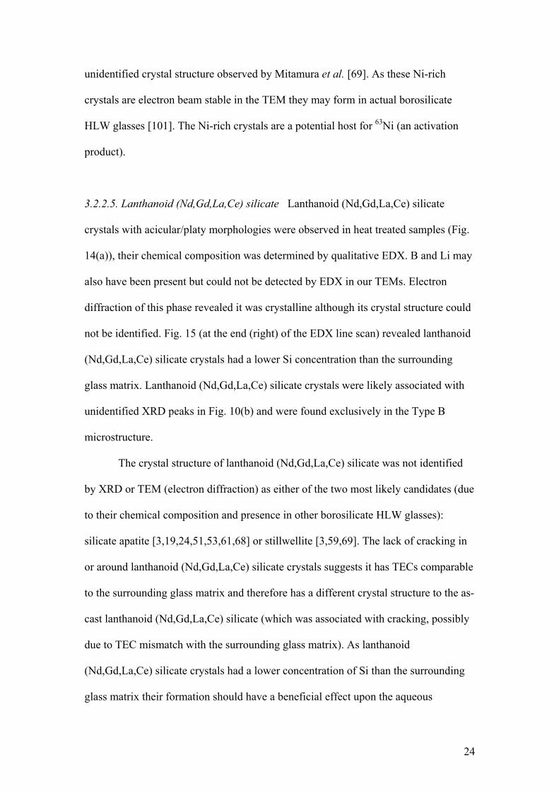
3.2.2.5. Lanthanoid (Nd,Gd,La,Ce) silicate Lanthanoid (Nd,Gd,La,Ce) silicate
crystals with acicular/platy morphologies were observed in heat treated samples (Fig.
14(a)), their chemical composition was determined by qualitative EDX. B and Li may
also have been present but could not be detected by EDX in our TEMs. Electron
diffraction of this phase revealed it was crystalline although its crystal structure could
not be identified. Fig. 15 (at the end (right) of the EDX line scan) revealed lanthanoid
(Nd,Gd,La,Ce) silicate crystals had a lower Si concentration than the surrounding
glass matrix. Lanthanoid (Nd,Gd,La,Ce) silicate crystals were likely associated with
unidentified XRD peaks in Fig. 10(b) and were found exclusively in the Type B
microstructure.
The crystal structure of lanthanoid (Nd,Gd,La,Ce) silicate was not identified
by XRD or TEM (electron diffraction) as either of the two most likely candidates (due
to their chemical composition and presence in other borosilicate HLW glasses):
silicate apatite [3,19,24,51,53,61,68] or stillwellite [3,59,69]. The lack of cracking in
or around lanthanoid (Nd,Gd,La,Ce) silicate crystals suggests it has TECs comparable
to the surrounding glass matrix and therefore has a different crystal structure to the as-
cast lanthanoid (Nd,Gd,La,Ce) silicate (which was associated with cracking, possibly
due to TEC mismatch with the surrounding glass matrix). As lanthanoid
(Nd,Gd,La,Ce) silicate crystals had a lower concentration of Si than the surrounding
glass matrix their formation should have a beneficial effect upon the aqueous
24
durability of the surrounding glass and hence wasteform. The stability of lanthanoid
(Nd,Gd,La,Ce) silicate crystals under the electron beam suggests they may form in
actual borosilicate HLW glasses [101]. Lanthanoid (Nd,Gd,La,Ce) silicate crystals are
a potential host for Am and Cm as both are present in the +3 oxidation state in
borosilicate glass [51] and have similar ionic radii to Nd [92]. Considering these
positives, if this phase also has a high aqueous durability then it has the potential to be
the basis of a glass-ceramic wasteform for Am and Cm.
3.2.2.6. LiNaZrSi6O15 (zektzerite) LiNaZrSi6O15 (zektzerite, orthorhombic crystal
system, space group Cmca) was identified in heat treated samples by XRD (labelled ○
in Fig. 10(b)) using ICDD card [29-835]. Zektzerite crystals had acicular
morphologies (Figs. 14(b) and 15(a)). An EDX line scan (Fig. 15) revealed zektzerite
crystals had a higher concentration of Si and Zr than the surrounding glass matrix.
Zektzerite crystals had cracks emanating from them perpendicular to the long axis of
the crystals and also displayed internal cracking (Figs. 14(b) and 15(a)). Fig. 14(b)
shows acicular zektzerite crystals penetrating lanthanoid (Nd,Gd,La,Ce) silicate
crystals. Zektzerite crystals were not observed in heat treated glass samples by TEM
and were found exclusively in the Type B microstructure.
Zektzerite crystals have previously been noted in a borosilicate HLW glass
[59]. Zektzerite crystals are enriched in ZrO2 (theoretically 23.26 wt%/12.5 mol%)
and SiO2 (theoretically 68.06 wt%/75 mol%) compared to the glass matrix. As
zektzerite crystals require six of the eight moles for their formation to be SiO2 their
crystallisation in a borosilicate HLW glass will likely be detrimental to the aqueous
durability of the surrounding glass matrix and hence wasteform. The thermal
expansion behaviour of zektzerite crystals detailed in Table 3 appears inconsistent
25
with the cracking observed in heat treated samples, where cracks are perpendicular to
the long axis of the acicular crystals. This indicates that the crystallographic axis
associated with the long axis of the crystal has a smaller or even negative thermal
expansion coefficient compared to the other axes. The data of Shaikh [114] agree with
observed cracking by indicating that the crystallographic c-axis has a negative TEC,
meaning the crystal will expand along this axis on cooling thereby putting the glass
matrix in this direction into tension while the crystal itself is in compression along this
axis. This would cause stress and eventual cracking in the glass matrix perpendicular
to the crystallographic c-axis, indicating that the long axis of the crystal is also the
crystallographic c-axis. Glass matrix cracking around zektzerite crystals may increase
wasteform surface area, which could lower the overall aqueous durability of the
wasteform [44]. As zektzerite crystals often penetrated lanthanoid (Nd,Gd,La,Ce)
silicate crystals it is concluded that they crystallised first.
Zektzerite crystals are a potential host for 93Zr and U [109]. Zektzerite crystals
are also a potential host for 126Sn because Sn is predominantly in the +4 oxidation
state and coordinated to six oxygens in borosilicate HLW glasses [115] (as is Zr in
borosilicate HLW glasses and zektzerite [116]) and has a similar ionic radius to Zr4+
[92], demonstrated by LiNaSnSi6O15 being isostructural with zektzerite [113].
Zektzerite crystals have been reported to form in the altered surface layers of a
borosilicate HLW glass during high temperature aqueous durability testing [109].
4. Conclusions
Insufficient reaction time in the glass melter between simulated HLW calcine
and base glass frit resulted in as-cast samples with inhomogeneous microstructures.
26
The observed variability in microstructural homogeneity of as-cast samples indicates
inconsistent process control during inactive commissioning of the full-scale
vitrification line. This is to be expected as the trial vitrification runs were used to
determine optimum processing conditions. The differing devitrification behaviour (in
terms of microstructure and crystal phase composition) of as-cast samples upon heat
treatment (to simulate the retarded cooling experienced by radiogenically heated
HLW glasses after pouring) was a direct result of their as-cast microstructural
homogeneity, despite samples having identical chemical compositions. This illustrates
the importance of consistently maintaining optimal process control during HLW
vitrification.
The potential incorporation of HLW radionuclides into identified crystal
phases has been determined: Pd–Te alloy (107Pd and 79Se), (Cr,Fe,Ni,Ru)3O4 (63Ni),
Zr1−x−yCexGdyO2−0.5y (93Zr, Pu and U), both lanthanoid (Nd,Gd,La,Ce) silicates (Am
and Cm), (Na,Sr,Nd,La)MoO4 (90Sr, Am and Cm), Ce1−x−yZrxGdyO2−0.5y (93Zr, Pu and
U), the Ni-rich phase (63Ni) and zektzerite (93Zr, 126Sn and U). Preferential
partitioning of SiO2 into cristobalite and zektzerite has also been identified. The
platinoid phases (RuO2 and Pd–Te alloy) acted as nucleation sites for further
crystallisation on heat treatment of as-cast samples. The potential effect of
crystallisation on wasteform aqueous durability has been assessed, with a water-
soluble crystal phase (Na3Li(MoO4)2·6H2O) and crystal phases which decrease the
aqueous durability of the surrounding glass matrix (cristobalite and zektzerite) being
identified. Cracking in as-cast and heat treated glass samples was attributed to thermal
expansion mismatch between certain crystal phases (RuO2, cristobalite (both α and β),
(Na,Sr,Nd,La)MoO4 and zektzerite) and the surrounding glass matrix, as well as the
cristobalite α–β phase transition, on cooling.
27
Increasing the quantity of Al2O3 in Oxide glass may increase the aqueous
durability of this wasteform and prevent the amorphous phase separation of its glass
matrix and the crystallisation of cristobalite. The lanthanoid (Nd,Gd,La,Ce) silicate
formed in heat treated samples is a potential host phase for Am and Cm, and is worthy
of further investigation.
Acknowledgements
The authors are indebted to Prof. Ian L. Pegg for granting P.B.R. a research
visit to the Vitreous State Laboratory (VSL), The Catholic University of America,
Washington, DC, USA. P.B.R. is also extremely grateful to the staff and students of
the VSL for all their help and generosity during his visit. For funding this visit we
thank the Sheffield Metallurgical and Engineering Association, the Laverick–
Webster–Hewitt Travelling Fellowship, the Tom Jackson Travel Fund and the
Armourers & Brasiers' Gauntlet Trust in conjunction with British Alcan Aluminium.
The EPSRC (Industrial CASE studentship award number 01300676), Nexia Solutions
Ltd (previously named Nuclear Sciences and Technology Services) and BNFL are
thanked for funding this work. We are forever in debt to our colleague, the late Prof.
Peter F. James, who was the inspiration behind this work and is sadly missed.
References
[1] M.J. Larkin, Nucl. Energy 25 (6) (1986) 343–54.
[2] J.A.C. Marples, Glass Technol. 29 (6) (1988) 230–47.
28
[3] W. Lutze, in: W. Lutze, R.C. Ewing (Eds.), Radioactive Waste Forms for the
Future, North-Holland, Amsterdam, 1988, pp. 1–159.
[4] I.W. Donald, B.L. Metcalfe, R.N.J. Taylor, J. Mater. Sci. 32 (22) (1997) 5851–87.
[5] M.I. Ojovan, W.E. Lee, An Introduction to Nuclear Waste Immobilisation,
Elsevier Ltd, Oxford, 2005.
[6] W.E. Lee, M.I. Ojovan, M.C. Stennett, N.C. Hyatt, Adv. Appl. Ceram. 105 (1)
(2006) 3–12.
[7] P.B. Rose, PhD thesis, University of Sheffield, Sheffield, UK, 2008.
[8] G. Roth, S. Weisenburger, W. Grünewald, Y. Gauthier, in: Proceedings of the 8th
International Conference on Radioactive Waste Management and Environmental
Remediation (ICEM'01, Bruges, Belgium), vol. 3, ASME, New York, 2002, pp.
1563–8.
[9] Q. Yan, A.C. Buechele, S. Hu, E. Wang, S.S. Fu, Ceram. Trans. 61 (1995) 167–
76.
[10] B.-F. Zhu, D.E. Clark, L.L. Hench, G.G. Wicks, J. Non-Cryst. Solids 80 (1–3)
(1986) 324–34.
[11] S. Komarneni, R. Roy, D.M. Roy, Nucl. Technol. 62 (1983) 71–4.
[12] M. Le Grand, PhD thesis, Université Paris 7 – Denis Diderot, Paris, France,
1999.
[13] E. Schiewer, H. Rabe, S. Weisenburger, Mater. Res. Soc. Symp. Proc. 11 (1982)
289–97.
[14] A.G. Blasewitz, BNWL-1401, Pacific Northwest Laboratory, Richland, WA,
USA, 1970.
[15] D. Caurant, O. Majérus, E. Fadel, M. Lenoir, C. Gervais, O. Pinet, J. Am. Ceram.
Soc. 90 (3) (2007) 774–83.
29
[16] A.K. Dé, B. Luckscheiter, W. Lutze, G. Malow, E. Schiewer, Am. Ceram. Soc.
Bull. (Ceram. Bull.) 55 (5) (1976) 500–3.
[17] A.R. Hall, J.T. Dalton, B. Hudson, J.A.C. Marples, in: Management of
Radioactive Wastes from the Nuclear Fuel Cycle, Proc. Symp., vol. 2, IAEA, Vienna,
1976, pp. 3–14.
[18] C.P. Kaushik, R.K. Mishra, P. Sengupta, A. Kumar, D. Das, G.B. Kale, K. Raj, J.
Nucl. Mater. 358 (2–3) (2006) 129–38.
[19] K. Kawamura, J. Ohuchi, Mater. Res. Soc. Symp. Proc. 353 (1995) 87–93.
[20] S. Morgan, PhD thesis, University of Sheffield, Sheffield, UK, 2005.
[21] J.B. Morris, B.E. Chidley, in: Management of Radioactive Wastes from the
Nuclear Fuel Cycle, Proc. Symp., vol. 1, IAEA, Vienna, 1976, pp. 241–58.
[22] R. Short, PhD thesis, University of Sheffield, Sheffield, UK, 2004.
[23] G.K. Sullivan, M.H. Langowski, P. Hrma, Ceram. Trans. 61 (1995) 187–93.
[24] J.V. Crum, J.D. Vienna, D.K. Peeler, I.A. Reamer, D.J. Pittman, Ceram. Trans.
132 (2002) 267–75.
[25] J.E. Mendel, W.A. Ross, F.P. Roberts, R.P. Turcotte, Y.B. Katayama, J.H.
Westsik Jr, in: Management of Radioactive Wastes from the Nuclear Fuel Cycle,
Proc. Symp., vol. 2, IAEA, Vienna, 1976, pp. 49–61.
[26] H. Mitamura, T. Banba, T. Murakami, Nucl. Chem. Waste Manag. 6 (3–4)
(1986) 223–31.
[27] D.B. Spilman, L.L. Hench, D.E. Clark, Nucl. Chem. Waste Manag. 6 (2) (1986)
107–19.
[28] H. Li, P. Hrma, J.D. Vienna, Ceram. Trans. 119 (2001) 237–45.
[29] D. Manara, A. Grandjean, O. Pinet, J.L. Dussossoy, D.R. Neuville, J. Non-Cryst.
Solids 353 (1) (2007) 12–23.
30
[30] D.A. McKeown, I.S. Muller, H. Gan, I.L. Pegg, C.A. Kendziora, J. Non-Cryst.
Solids 288 (1–3) (2001) 191–9.
[31] I.L. Pegg, I. Joseph, in: C.H. Oh (Ed.), Hazardous and Radioactive Waste
Treatment Technologies Handbook, CRC Press, Boca Raton, 2001, 4.2, pp. 1–27.
[32] P. Sengupta, J. Mittra, G.B. Kale, J. Nucl. Mater. 350 (1) (2006) 66–73.
[33] R.J. Short, R.J. Hand, N.C. Hyatt, G. Möbus, J. Nucl. Mater. 340 (2–3) (2005)
179–86.
[34] J.D. Vienna, PhD thesis, Washington State University, Pullman, WA, USA,
2002.
[35] P. Hrma, L.M. Bagaasen, A.E. Beck, T.M. Brouns, D.D. Caldwell, M.L. Elliott,
J. Matyas, K.B.C. Minister, M.J. Schweiger, D.M. Strachan, B.P. Tinsley, G.W.
Hollenberg, PNNL-15193, Pacific Northwest National Laboratory, Richland, WA,
USA, 2005.
[36] D.S. Kim, C.Z. Soderquist, J.P. Icenhower, B.P. McGrail, R.D. Scheele, B.K.
McNamara, L.M. Bagaasen, M.J. Schweiger, J.V. Crum, D.J. Yeager, J. Matyáš, L.P.
Darnell, H.T. Schaef, A.T. Owen, A.E. Kozelisky, L.A. Snow, M.J. Steele, PNNL-
15131, Pacific Northwest National Laboratory, Richland, WA, USA, 2005.
[37] M.H. Langowski, J.G. Darab, P.A. Smith, PNNL-11052, Pacific Northwest
National Laboratory, Richland, WA, USA, 1996.
[38] A.V. Demin, M.I. Fedorova, Yu.I. Matyunin, At. Energy (N. Y.) 80 (3) (1996)
178–81.
[39] L. Galoisy, G. Calas, G. Morin, S. Pugnet, C. Fillet, J. Mater. Res. 13 (5) (1998)
1124–7.
[40] W. Grünewald, G. Roth, W. Tobie, K. Weiβ, S. Weisenburger, Glass Technol.:
Eur. J. Glass Sci. Technol., Part A 49 (6) (2008) 266–78.
31
[41] Ch. Krause, B. Luckscheiter, J. Mater. Res. 6 (12) (1991) 2535–46.
[42] M.J. LaMont, P. Hrma, Ceram. Trans. 87 (1998) 343–8.
[43] P. Izak, P. Hrma, B.W. Arey, T.J. Plaisted, J. Non-Cryst. Solids 289 (1–3) (2001)
17–29.
[44] D.F. Bickford, A. Applewhite-Ramsey, C.M. Jantzen, K.G. Brown, J. Am.
Ceram. Soc. 73 (10) (1990) 2896–902.
[45] D.S. Goldman, D.W. Brite, J. Am. Ceram. Soc. 69 (5) (1986) 411–3.
[46] C. Simonnet, A. Grandjean, J. Non-Cryst. Solids 351 (19–20) (2005) 1611–8.
[47] D.E. Clark, L.L. Hench, Nucl. Chem. Waste Manag. 2 (2) (1981) 93–101.
[48] P. Hrma, B.J. Riley, J.D. Vienna, Ceram. Trans. 143 (2003) 291–8.
[49] D.-S. Kim, D.K. Peeler, P. Hrma, Ceram. Trans. 61 (1995) 177–85.
[50] J.F. Sproull, S.L. Marra, C.M. Jantzen, Mater. Res. Soc. Symp. Proc. 333 (1994)
15–25.
[51] D. Caurant, O. Majerus, P. Loiseau, I. Bardez, N. Baffier, J.L. Dussossoy, J.
Nucl. Mater. 354 (1–3) (2006) 143–62.
[52] Hj. Matzke, Inorg. Chim. Acta 94 (1–3) (1984) 142–3.
[53] A. Quintas, O. Majérus, D. Caurant, J.-L. Dussossoy, P. Vermaut, J. Am. Ceram.
Soc. 90 (3) (2007) 712–9.
[54] F. Bart, J.L. Dussossoy, C. Fillet, Mater. Res. Soc. Symp. Proc. 663 (2001) 161–
7.
[55] L. Bouchet, A. Rivoallan, J.F. Milot, F. Bart, Atalante 2000 Conference,
Avignon, France, 2000, P4-26.
[56] P.K. Abraitis, PhD thesis, University of Manchester, Manchester, UK, 1999.
[57] S.V. Raman, B.A. Scholes, A. Erickson, A.A. Zareba, Ceram. Trans. 143 (2003)
185–98.
32
[58] A.C. Buechele, X. Feng, H. Gu, I.L. Pegg, Mater. Res. Soc. Symp. Proc. 176
(1990) 393–402.
[59] N.C. Hyatt, K.J. Taylor, F.G.F. Gibb, W.E. Lee, Glass Technol. 45 (2) (2004)
68–70.
[60] C.M. Jantzen, D.F. Bickford, D.G. Karraker, Adv. Ceram. 8 (1984) 30–8.
[61] L. Kahl, Nucl. Chem. Waste Manag. 2 (2) (1981) 143–6.
[62] D.-S. Kim, P. Hrma, D.E. Smith, M.J. Schweiger, Ceram. Trans. 39 (1994) 179–
89.
[63] B. Luckscheiter, M. Nesovic, Waste Manag. 16 (7) (1996) 571–8.
[64] W. Lutze, J. Borchardt, A.K. Dé, in: G.J. McCarthy (Ed.), Scientific Basis for
Nuclear Waste Management I, Plenum Press, New York, 1979, pp. 69–81.
[65] Hj. Matzke, L. Kahl, J. Saidl, J.L. Routbort, Adv. Ceram. 8 (1984) 697–709.
[66] O. Pinet, S. Mure, J. Non-Cryst. Solids 355 (3) (2009) 221–7.
[67] S.K. Sundaram, J.M. Perez Jr, PNNL-13347, Pacific Northwest National
Laboratory, Richland, WA, USA, 2000.
[68] R.P. Turcotte, J.W. Wald, R.P. May, in: C.J.M. Northrup Jr (Ed.), Scientific
Basis for Nuclear Waste Management II, Plenum Press, New York, 1980, pp. 141–6.
[69] H. Mitamura, T. Murakami, T. Banba, J. Nucl. Mater. 136 (1) (1985) 104–16.
[70] G. Roth, S. Weisenburger, Nucl. Eng. Des. 202 (2–3) (2000) 197–207.
[71] P. Cheron, Ph. Chevalier, R. Do Quang, G. Tanguy, M. Sourrouille, S. Woignier,
N. Senoo, T. Banba, K. Kuramoto, T. Yamaguchi, K. Shimizu, C. Fillet, N. Jacquet-
Francillon, J. Godard, J.L. Dussossoy, F. Pacaud, J.G. Charbonnel, Mater. Res. Soc.
Symp. Proc. 353 (1995) 55–62.
[72] F. Pacaud, C. Fillet, N. Jacquet-Francillon, Mater. Res. Soc. Symp. Proc. 257
(1992) 161–7.
33
[73] D.F. Bickford, C.M. Jantzen, J. Non-Cryst. Solids 84 (1–3) (1986) 299–307.
[74] K.V.K. Rao, L. Iyengar, Acta. Crystallogr., Sect. A: Cryst. Phys., Diffr., Theor.
Gen. Crystallogr. 25 (2) (1969) 302–3.
[75] D.F. Bickford, C.M. Jantzen, Mater. Res. Soc. Symp. Proc. 26 (1984) 557–66.
[76] H. Okamoto, J. Phase Equilib. 13 (1) (1992) 73–8.
[77] H. Okamoto, J. Phase Equilib. 15 (3) (1994) 369.
[78] H. Okamoto, J. Phase Equilib. 13 (1) (1992) 69–72.
[79] A. Della Giusta, F. Princivalle, S. Carbonin, Mineral. Petrol. 37 (3–4) (1987)
315–21.
[80] C.J. Capobianco, M.J. Drake, Geochim. Cosmochim. Acta 54 (3) (1990) 869–74.
[81] P. Hrma, J.V. Crum, P.R. Bredt, L.R. Greenwood, B.W. Arey, H.D. Smith, J.
Nucl. Mater. 345 (1) (2005) 31–40.
[82] K.E. Sickafus, L. Minervini, R.W. Grimes, J.A. Valdez, M. Ishimaru, F. Li, K.J.
McClellan, T. Hartmann, Science 289 (5480) (2000) 748–51.
[83] A.C. Buechele, I.S. Muller, I.L. Pegg, C.-W. Kim, E. Yaschenko, Ceram. Trans.
61 (1995) 203–11.
[84] I.S. Muller, A.C. Buechele, F. Perez-Cardenas, H. Gan, I.L. Pegg, Mater. Res.
Soc. Symp. Proc. 556 (1999) 271–8.
[85] P. Bouvier, E. Djuardo, G. Lucazeau, T. Le Bihan, Phys. Rev. B: Condens.
Matter Mater. Phys. 62 (13) (2000) 8731–7.
[86] T.P. O'Holleran, S.G. Johnson, P.C. Kong, B.A. Staples, Ceram. Trans. 87 (1998)
541–50.
[87] M. Yashima, H. Arashi, M. Kakihana, M. Yoshimura, J. Am. Ceram. Soc. 77 (4)
(1994) 1067–71.
[88] W. Lutze, R.C. Ewing, Ceram. Trans. 61 (1995) 357–64.
34
[89] N. Jacquet-Francillon, F. Pacaud, P. Queille, Mater. Res. Soc. Symp. Proc. 11
(1982) 249–59.
[90] W.L. Gong, W. Lutze, R.C. Ewing, J. Nucl. Mater. 278 (1) (2000) 73–84.
[91] A. Martínez-Arias, M. Fernández-García, V. Ballesteros, L.N. Salamanca, J.C.
Conesa, C. Otero, J. Soria, Langmuir 15 (14) (1999) 4796–802.
[92] R.D. Shannon, Acta Crystallogr., Sect. A: Cryst. Phys., Diffr., Theor. Gen.
Crystallogr. 32 (5) (1976) 751–67.
[93] M. Arbab, V.K. Marghussian, H. Sarpoolaky, M. Kord, Ceram. Int. 33 (6) (2007)
943–50.
[94] C.M. Jantzen, K.G. Brown, J.B. Pickett, Ceram. Trans. 119 (2001) 271–80.
[95] J.-H. Jean, T.-H. Kuan, T.K. Gupta, J. Mater. Sci. Lett. 14 (15) (1995) 1068–70.
[96] B.J. Riley, P. Hrma, J. Rosario, J.D. Vienna, Ceram. Trans. 132 (2002) 257–65.
[97] J.J. Pluth, J.V. Smith, J. Faber Jr, J. Appl. Phys. 57 (4) (1985) 1045–9.
[98] D.R. Peacor, Z. Kristallogr., Kristallgeom., Kristallphys., Kristallchem. 138
(1973) 274–98.
[99] I.P. Swainson, M.T. Dove, Phys. Chem. Miner. 22 (1) (1995) 61–5.
[100] C.J. McConville, W.E. Lee, J.H. Sharp, Br. Ceram. Trans. 97 (4) (1998) 162–8.
[101] K. Sun, L.M. Wang, R.C. Ewing, W.J. Weber, Nucl. Instrum. Methods Phys.
Res., Sect. B 218 (2004) 368–74.
[102] P.K. Abraitis, F.R. Livens, J.E. Monteith, J.S. Small, D.P. Trivedi, D.J.
Vaughan, R.A. Wogelius, Appl. Geochem. 15 (9) (2000) 1399–416.
[103] Aa. Barkatt, P.B. Macedo, W. Sousanpour, Al. Barkatt, M.A. Boroomand, C.F.
Fisher, J.J. Shirron, P. Szoke, V.L. Rogers, Nucl. Chem. Waste Manag. 4 (2) (1983)
153–69.
35
[104] D.E. Clark, C.A. Maurer, A.R. Jurgensen, L. Urwongse, Mater. Res. Soc. Symp.
Proc. 11 (1982) 1–11.
[105] R.M. Hazen, L.W. Finger, J.W.E. Mariathasan, J. Phys. Chem. Solids 46 (2)
(1985) 253–63.
[106] S.N. Achary, S.J. Patwe, M.D. Mathews, A.K. Tyagi, J. Phys. Chem. Solids 67
(4) (2006) 774–81.
[107] A. Abdelouas, J.-L. Crovisier, W. Lutze, B. Grambow, J.-C. Dran, R. Müller, J.
Nucl. Mater. 240 (2) (1997) 100–11.
[108] W.L. Gong, L.M. Wang, R.C. Ewing, E. Vernaz, J.K. Bates, W.L. Ebert, J.
Nucl. Mater. 254 (2–3) (1998) 249–65.
[109] D. Savage, J.E. Robbins, R.J. Merriman, Mineral. Mag. 49 (351) (1985) 195–
201.
[110] D. Taylor, Trans. J. Br. Ceram. Soc. 83 (2) (1984) 32–7.
[111] R.K. Mishra, P. Sengupta, C.P. Kaushik, A.K. Tyagi, G.B. Kale, K. Raj, J.
Nucl. Mater. 360 (2) (2007) 143–50.
[112] C.-W. Kim, I.S. Muller, A.C. Buechele, I.L. Pegg, P.B. Macedo, Mater. Res.
Soc. Symp. Proc. 412 (1996) 149–56.
[113] J.M. Marr, F.P. Glasser, Mineral. Mag. 43 (325) (1979) 171–3.
[114] A.M. Shaikh, J. Indian Inst. Sci. 87 (2) (2007) 237–59.
[115] D.A. McKeown, A.C. Buechele, H. Gan, I.L. Pegg, J. Non-Cryst. Solids 354
(27) (2008) 3142–51.
[116] D.A. McKeown, I.S. Muller, A.C. Buechele, I.L. Pegg, C.A. Kendziora, C.R.
Scales, Mater. Res. Soc. Symp. Proc. 556 (1999) 305–12.
Figure captions
36
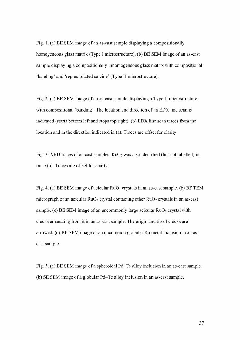
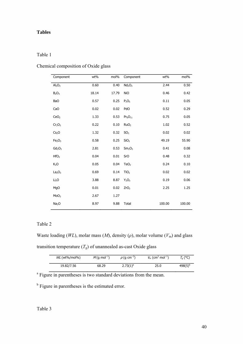
Fig. 1. (a) BE SEM image of an as-cast sample displaying a compositionally
homogeneous glass matrix (Type I microstructure). (b) BE SEM image of an as-cast
sample displaying a compositionally inhomogeneous glass matrix with compositional
‘banding’ and ‘reprecipitated calcine’ (Type II microstructure).
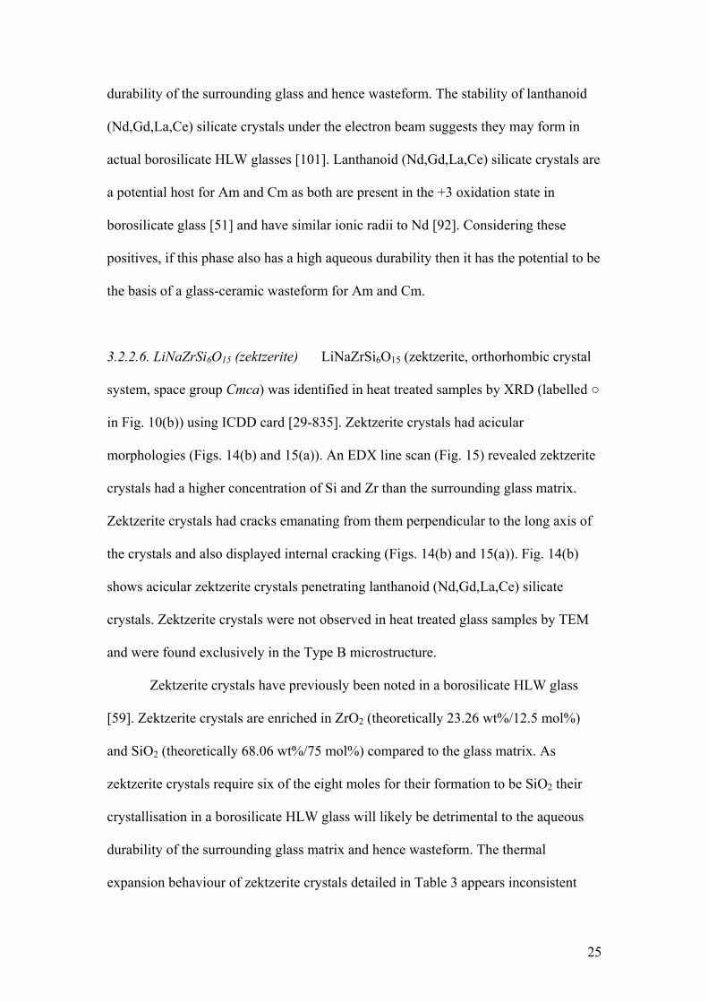
Fig. 2. (a) BE SEM image of an as-cast sample displaying a Type II microstructure
with compositional ‘banding’. The location and direction of an EDX line scan is
indicated (starts bottom left and stops top right). (b) EDX line scan traces from the
location and in the direction indicated in (a). Traces are offset for clarity.
Fig. 3. XRD traces of as-cast samples. RuO2 was also identified (but not labelled) in
trace (b). Traces are offset for clarity.
Fig. 4. (a) BE SEM image of acicular RuO2 crystals in an as-cast sample. (b) BF TEM
micrograph of an acicular RuO2 crystal contacting other RuO2 crystals in an as-cast
sample. (c) BE SEM image of an uncommonly large acicular RuO2 crystal with
cracks emanating from it in an as-cast sample. The origin and tip of cracks are
arrowed. (d) BE SEM image of an uncommon globular Ru metal inclusion in an as-
cast sample.
Fig. 5. (a) BE SEM image of a spheroidal Pd–Te alloy inclusion in an as-cast sample.
(b) SE SEM image of a globular Pd–Te alloy inclusion in an as-cast sample.
37
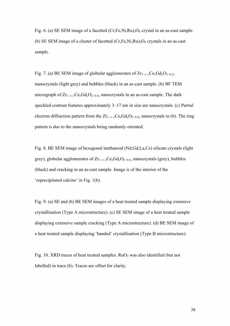
Fig. 6. (a) SE SEM image of a facetted (Cr,Fe,Ni,Ru)3O4 crystal in an as-cast sample.
(b) SE SEM image of a cluster of facetted (Cr,Fe,Ni,Ru)3O4 crystals in an as-cast
sample.
Fig. 7. (a) BE SEM image of globular agglomerates of Zr1−x−yCexGdyO2−0.5y
nanocrystals (light grey) and bubbles (black) in an as-cast sample. (b) BF TEM
micrograph of Zr1−x−yCexGdyO2−0.5y nanocrystals in an as-cast sample. The dark
speckled contrast features approximately 3–17 nm in size are nanocrystals. (c) Partial
electron diffraction pattern from the Zr1−x−yCexGdyO2−0.5y nanocrystals in (b). The ring
pattern is due to the nanocrystals being randomly oriented.
Fig. 8. BE SEM image of hexagonal lanthanoid (Nd,Gd,La,Ce) silicate crystals (light
grey), globular agglomerates of Zr1−x−yCexGdyO2−0.5y nanocrystals (grey), bubbles
(black) and cracking in an as-cast sample. Image is of the interior of the
‘reprecipitated calcine’ in Fig. 1(b).
Fig. 9. (a) SE and (b) BE SEM images of a heat treated sample displaying extensive
crystallisation (Type A microstructure). (c) SE SEM image of a heat treated sample
displaying extensive sample cracking (Type A microstructure). (d) BE SEM image of
a heat treated sample displaying ‘banded’ crystallisation (Type B microstructure).
Fig. 10. XRD traces of heat treated samples. RuO2 was also identified (but not
labelled) in trace (b). Traces are offset for clarity.
38
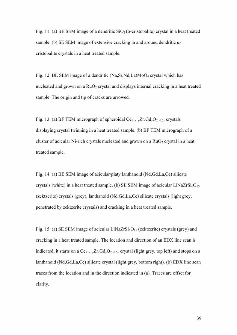
Fig. 11. (a) BE SEM image of a dendritic SiO2 (α-cristobalite) crystal in a heat treated
sample. (b) SE SEM image of extensive cracking in and around dendritic α-
cristobalite crystals in a heat treated sample.
Fig. 12. BE SEM image of a dendritic (Na,Sr,Nd,La)MoO4 crystal which has
nucleated and grown on a RuO2 crystal and displays internal cracking in a heat treated
sample. The origin and tip of cracks are arrowed.
Fig. 13. (a) BF TEM micrograph of spheroidal Ce1−x−yZrxGdyO2−0.5y crystals
displaying crystal twinning in a heat treated sample. (b) BF TEM micrograph of a
cluster of acicular Ni-rich crystals nucleated and grown on a RuO2 crystal in a heat
treated sample.
Fig. 14. (a) BE SEM image of acicular/platy lanthanoid (Nd,Gd,La,Ce) silicate
crystals (white) in a heat treated sample. (b) SE SEM image of acicular LiNaZrSi6O15
(zektzerite) crystals (grey), lanthanoid (Nd,Gd,La,Ce) silicate crystals (light grey,
penetrated by zektzerite crystals) and cracking in a heat treated sample.
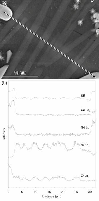
Fig. 15. (a) SE SEM image of acicular LiNaZrSi6O15 (zektzerite) crystals (grey) and
cracking in a heat treated sample. The location and direction of an EDX line scan is
indicated, it starts on a Ce1−x−yZrxGdyO2−0.5y crystal (light grey, top left) and stops on a
lanthanoid (Nd,Gd,La,Ce) silicate crystal (light grey, bottom right). (b) EDX line scan
traces from the location and in the direction indicated in (a). Traces are offset for
clarity.
39
Tables
Table 1
Chemical composition of Oxide glass
Component wt% mol% Component wt% mol%
Al2O3 0.60 0.40 Nd2O3 2.44 0.50
BB2O3 18.14 17.79 NiO 0.46 0.42
BaO 0.57 0.25 P2O5 0.11 0.05
CaO 0.02 0.02 PdO 0.52 0.29
CeO2 1.33 0.53 Pr6O11 0.75 0.05
Cr2O3 0.22 0.10 RuO2 1.02 0.52
Cs2O 1.32 0.32 SO3 0.02 0.02
Fe2O3 0.58 0.25 SiO2 49.19 55.90
Gd2O3 2.81 0.53 Sm2O3 0.41 0.08
HfO2 0.04 0.01 SrO 0.48 0.32
K2O 0.05 0.04 TeO2 0.24 0.10
La2O3 0.69 0.14 TiO2 0.02 0.02
Li2O 3.88 8.87 Y2O3 0.19 0.06
MgO 0.01 0.02 ZrO2 2.25 1.25
MoO3 2.67 1.27
Na2O 8.97 9.88 Total 100.00 100.00
Table 2
Waste loading (WL), molar mass (M), density (ρ), molar volume (Vm) and glass
transition temperature (Tg) of unannealed as-cast Oxide glass
WL (wt%/mol%) M (g mol−1) ρ (g cm−3) Vm (cm3 mol−1) Tg (°C)
19.82/7.56 68.29 2.73(1)a 25.0 498(5)b
a Figure in parentheses is two standard deviations from the mean.
b Figure in parentheses is the estimated error.
Table 3
40
Mean linear (αl) and volumetric (αV) thermal expansion coefficients (TECs) of
borosilicate HLW glasses and relevant crystal phasesa over the specified temperature
ranges
Temperature range (°C) αl (× 10−6 K−1) αV (× 10−6 K−1) Reference(s)
Borosilicate HLW glasses RTb–Tg 8.0–10.0 24.0–30.0 [3,4]
Ruthenium dioxide (RuO2) 30–361 a = 9.7
c = −2.6
16.8 [74]
361–608 a = 13.0
c = −3.8
22.3
Cristobalite (SiO2) 23–200c
(α-cristobalite)
a = 19.1
c = 34.2
72.7 [97]
200–300
(α–β phase transition
region)
a = 112
c = 234
465 [97–99]
300–600
(β-cristobalite)
a = 4.9 14.6 [99]
Powellite (CaMoO4) 25–300 a = 11.7
c = 19.3
42.9 [106]
300–600 a = 13.1
c = 21.7
48.2
Zektzerite (LiNaZrSi6O15) 12–420 a = 4.3
b = 3.1
c = 4.8
12.2 [113]
420–630 a = 6.3
b = 6.0
c = 7.5
19.9
a Isostructural crystal phases of different chemical composition may have different
TECs.
b Room temperature.
c Also specified as 20–200 °C in the same reference, which would give mean TECs
(α) for a, c and V of 18.8, 33.6 and 71.4 × 10⁻⁶ K−1 respectively.
41
(b)
0 0.5 1 1.5 2Distance (mm)
Inte
nsity
BE
Ce Lα1
Cs Lα1
Gd Lα1
Mo Lα1
Nd Lα1
Ni Kα
Ru Lα1
Si Kα
Zr Lα1
10 20 30 40 50 60 70 802θ (°)
Inte
nsity
(a)
(b)
♦ = RuO2● = Pd–Te alloy◊ = (Cr,Fe,Ni,Ru)3O4□ = Na3Li(MoO4)2·6H2O
♦
♦
♦♦
♦
♦♦ ♦♦ ♦
♦
●●
●
◊ ◊◊ ◊ ◊ ◊
□□
□□
10 20 30 40 50 60 70 802θ (°)
Inte
nsity
(a)
(b)
♦ = RuO2● = Pd–Te alloy◊ = SiO2 (α-cristobalite)□ = (Na,Sr,Nd,La)MoO4■ = Ce1−x−yZrxGdyO2−0.5y○ = LiNaZrSi6O15 (zektzerite)
♦
♦♦♦ ♦
♦ ♦ ♦ ♦ ♦
●●
●
◊
◊ ◊ ◊◊ ◊ ◊
□
□ □□
□ □□ □□
□
■■ ■
■ ■ ■○
○
○
○
○○○○○○○○
○○
○○○
○○ ○ ○ ○○○ ○
(b)
0 5 10 15 20 25 30Distance (μm)
Inte
nsity
SE
Ce Lα1
Gd Lα1
Si Kα
Zr Lα1