Embed Size (px)
Citation preview

CRYSTAL CITY STATION ACCESS AND SECOND ENTRANCE STUDY
Final
February 2014
CRYSTAL CITY STATION ACCESS AND SECOND ENTRANCE STUDY

This page left intentionally blank.

CRYSTAL CITY STATION ACCESS AND SECOND ENTRANCE STUDY
Final Report ES - 1
Executive Summary
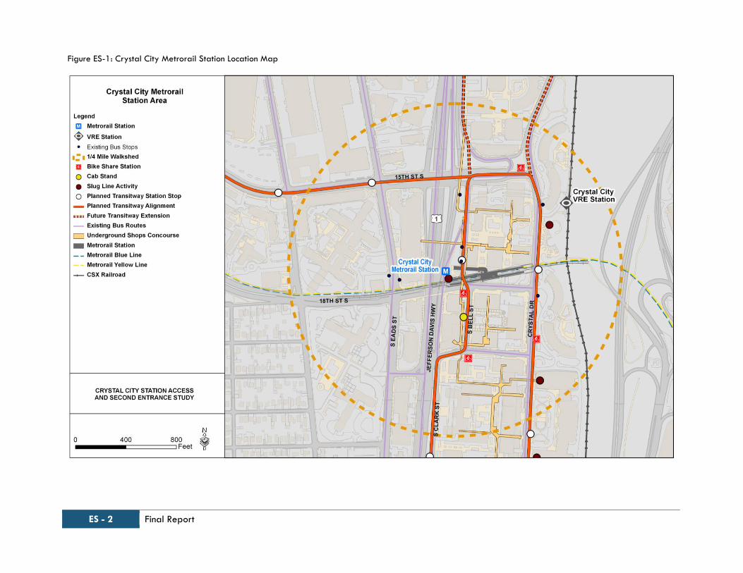
The Crystal City Metrorail Station is located
on the Metrorail Blue and Yellow lines in
the Crystal City neighborhood in Arlington
County, Virginia. The Crystal City Metrorail
Station has a single entrance, between
Clark and Bell Streets, just north of 18th
Street South, see Figure ES-1. The Crystal
City Metrorail Station is also accessible
from the elevator located just north of 18th
Street South, reached by a short pedestrian
pathway. Crystal City is also served by
Virginia Railway Express (VRE) - a
commuter rail service that connects the
Northern Virginia suburbs to Union Station
in Washington, D.C. The Crystal City VRE
Station is located within a close proximity
of the Metrorail station entrance.
Issues Identification
Based on the review of studies conducted
previously and the observations made
during site visits, several issues were
identified in the vicinity of the Crystal City
Metrorail Station. These are listed as
follows:
Lack of a direct route for many users to
the station entrance;
Need for additional signage;
Inadequate way-finding measures;
Need for better connections with other
modes – bicycles, Metrobuses, etc.; and
Long-term station facility constraints.
Many of these issues are driving the need
to consider construction of a second
entrance to the station, as well as to
evaluate other actions that would improve
multimodal access in the general vicinity of
the Crystal City Metrorail Station. The
following criteria were developed to
evaluate the placement and design of
potential second entrance locations and
other actions that would address the
identified concerns:
Improve access from Crystal Drive;
Improve access for all users;
Improve multimodal connectivity
(bicycles, buses, VRE, etc.);
Integrate with proposed re-
development and reinvestment;
Address long-term growth in ridership
(faregates, elevators, and escalators);
Environmental and community Impacts;
Constructability; and
Safety (mobility, evacuation etc.).
Preliminary Second Entrance
Alternatives
There were five initial alternatives
developed in coordination with the public
and project stakeholders in this category.
These alternatives are described below
and their general locations are shown in
Figure ES-2.
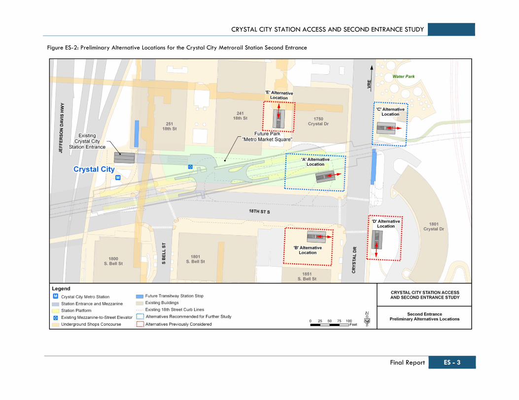
Alternative A: New entrance west of
Crystal Drive, north of 18th Street,
connecting to the existing mezzanine.
Alternative B: New entrance west of
Crystal Drive, south of 18th Street,
connecting to the existing mezzanine.
Alternative C: New entrance east of
Crystal Drive, south of Water Park,
requiring a new mezzanine.
Alternative D: New entrance east of
Crystal Drive, south of 18th Street,
requiring a new mezzanine.
Alternative E: Connection to the existing
Underground shopping mall, connecting to
the existing mezzanine through a new
passageway.
Initial Access Improvements
Initial Access Improvements include spot
improvements, intersection improvements at
three locations along 18th Street (Eads
Street, Clark/Bell Street, and Crystal
Drive). These include the addition of an
ADA ramp to the driveway near the
existing elevator and improving lighting at
the intersection of Underground and
Metrorail station entrance passageways.
Way-finding and signage locations are
included at strategic points in the vicinity of
the Metrorail station. These Initial Access
Improvements are shown in Figure ES-3.
ES - 2 Final Report
Figure ES-1: Crystal City Metrorail Station Location Map
CRYSTAL CITY STATION ACCESS AND SECOND ENTRANCE STUDY
Final Report ES - 3
Figure ES-2: Preliminary Alternative Locations for the Crystal City Metrorail Station Second Entrance

ES - 4 Final Report
Figure ES-3: Crystal City Metrorail Station – Initial Access Improvements Alternative
CRYSTAL CITY STATION ACCESS AND SECOND ENTRANCE STUDY
Final Report ES - 5
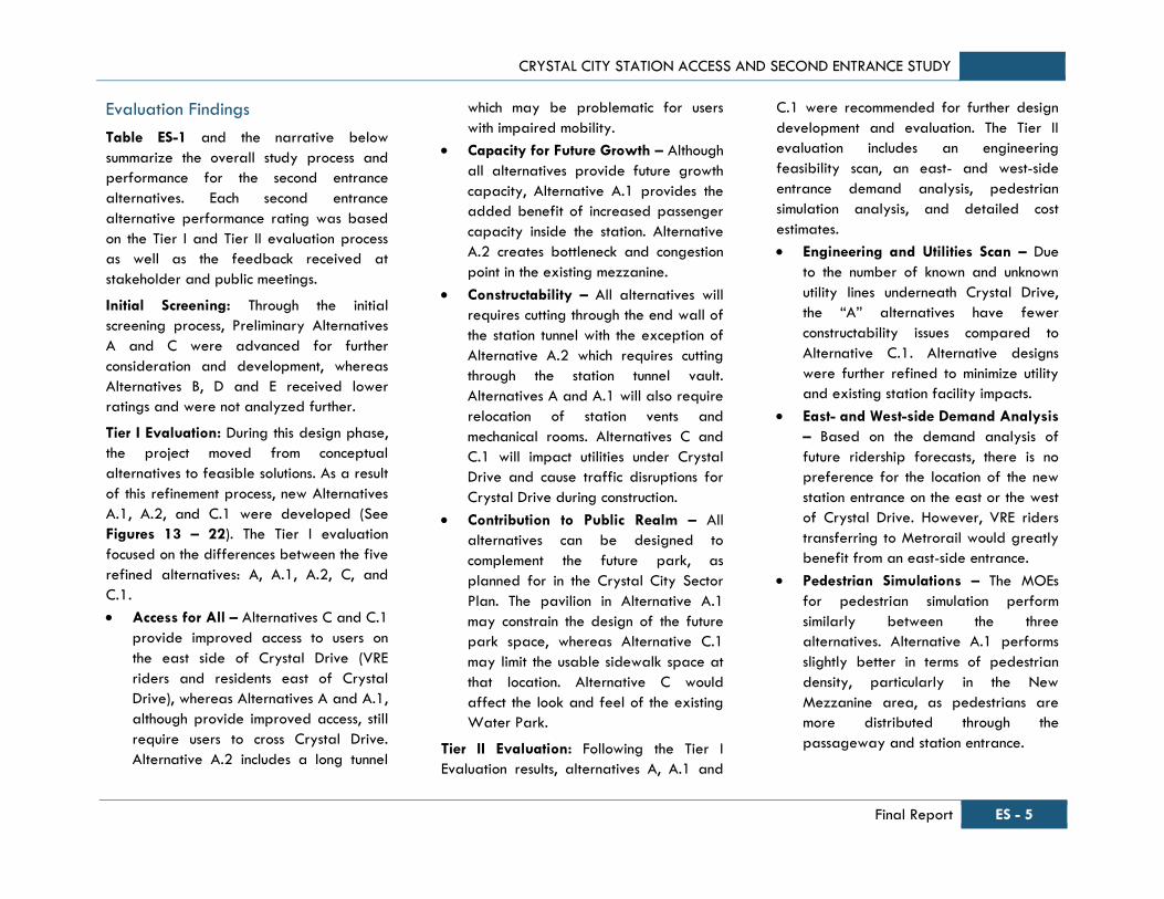
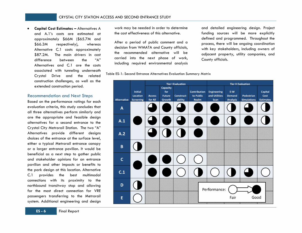
Evaluation Findings
Table ES-1 and the narrative below
summarize the overall study process and
performance for the second entrance
alternatives. Each second entrance
alternative performance rating was based
on the Tier I and Tier II evaluation process
as well as the feedback received at
stakeholder and public meetings.
Initial Screening: Through the initial
screening process, Preliminary Alternatives
A and C were advanced for further
consideration and development, whereas
Alternatives B, D and E received lower
ratings and were not analyzed further.
Tier I Evaluation: During this design phase,
the project moved from conceptual
alternatives to feasible solutions. As a result
of this refinement process, new Alternatives
A.1, A.2, and C.1 were developed (See
Figures 13 – 22). The Tier I evaluation
focused on the differences between the five
refined alternatives: A, A.1, A.2, C, and
C.1.
Access for All – Alternatives C and C.1
provide improved access to users on
the east side of Crystal Drive (VRE
riders and residents east of Crystal
Drive), whereas Alternatives A and A.1,
although provide improved access, still
require users to cross Crystal Drive.
Alternative A.2 includes a long tunnel
which may be problematic for users
with impaired mobility.
Capacity for Future Growth – Although
all alternatives provide future growth
capacity, Alternative A.1 provides the
added benefit of increased passenger
capacity inside the station. Alternative
A.2 creates bottleneck and congestion
point in the existing mezzanine.
Constructability – All alternatives will
requires cutting through the end wall of
the station tunnel with the exception of
Alternative A.2 which requires cutting
through the station tunnel vault.
Alternatives A and A.1 will also require
relocation of station vents and
mechanical rooms. Alternatives C and
C.1 will impact utilities under Crystal
Drive and cause traffic disruptions for
Crystal Drive during construction.
Contribution to Public Realm – All
alternatives can be designed to
complement the future park, as
planned for in the Crystal City Sector
Plan. The pavilion in Alternative A.1
may constrain the design of the future
park space, whereas Alternative C.1
may limit the usable sidewalk space at
that location. Alternative C would
affect the look and feel of the existing
Water Park.
Tier II Evaluation: Following the Tier I
Evaluation results, alternatives A, A.1 and
C.1 were recommended for further design
development and evaluation. The Tier II
evaluation includes an engineering
feasibility scan, an east- and west-side
entrance demand analysis, pedestrian
simulation analysis, and detailed cost
estimates.
Engineering and Utilities Scan – Due
to the number of known and unknown
utility lines underneath Crystal Drive,
the “A” alternatives have fewer
constructability issues compared to
Alternative C.1. Alternative designs
were further refined to minimize utility
and existing station facility impacts.
East- and West-side Demand Analysis
– Based on the demand analysis of
future ridership forecasts, there is no
preference for the location of the new
station entrance on the east or the west
of Crystal Drive. However, VRE riders
transferring to Metrorail would greatly
benefit from an east-side entrance.
Pedestrian Simulations – The MOEs
for pedestrian simulation perform
similarly between the three
alternatives. Alternative A.1 performs
slightly better in terms of pedestrian
density, particularly in the New
Mezzanine area, as pedestrians are
more distributed through the
passageway and station entrance.
CRYSTAL CITY STATION ACCESS AND SECOND ENTRANCE STUDY
ES - 6 Final Report
Table ES-1: Second Entrance Alternatives Evaluation Summary Matrix
Capital Cost Estimates – Alternatives A
and A.1’s costs are estimated at
approximately $66M ($65.7M and
$66.3M respectively), whereas
Alternative C.1 costs approximately
$87.2M. The main drivers in cost
difference between the “A”
Alternatives and C.1 are the costs
associated with tunneling underneath
Crystal Drive and the related
construction challenges, as well as the
extended construction period.
Recommendation and Next Steps
Based on the performance ratings for each
evaluation criteria, this study concludes that
all three alternatives perform similarly and
are the appropriate and feasible design
alternatives for a second entrance to the
Crystal City Metrorail Station. The two “A”
Alternatives provide different designs
choices of the entrance at the surface level,
either a typical Metrorail entrance canopy
or a larger entrance pavilion. It would be
beneficial as a next step to gather public
and stakeholder opinions for an entrance
pavilion and other impacts or benefits to
the park design at this location. Alternative
C.1 provides the best multimodal
connections with its proximity to the
northbound transitway stop and allowing
for the most direct connection for VRE
passengers transferring to the Metrorail
system. Additional engineering and design
work may be needed in order to determine
the cost effectiveness of this alternative.
After a period of public comment and a
decision from WMATA and County officials,
the recommended alternative will be
carried into the next phase of work,
including required environmental analysis
and detailed engineering design. Project
funding sources will be more explicitly
defined and programmed. Throughout the
process, there will be ongoing coordination
with key stakeholders, including owners of
adjacent property, utility companies, and
County officials.

CRYSTAL CITY STATION ACCESS AND SECOND ENTRANCE STUDY
Final Report i
Table of Contents
Executive Summary .................................................................................................................................................................................................................................. ES-1
1.0 Project Background .......................................................................................................................................................................................................................... 1
2.0 Purpose & Study Process ................................................................................................................................................................................................................ 3
3.0 Stakeholder Coordination & Public Involvement ....................................................................................................................................................................... 4
4.0 Existing Station Characteristics ...................................................................................................................................................................................................... 6
5.0 Alternatives Development and Initial Screening ..................................................................................................................................................................... 12
5.1. Initial Screening Evaluation Criteria ..................................................................................................................................................................................... 12
5.2. Alternatives Identified ............................................................................................................................................................................................................. 14
5.3. Evaluation of Preliminary Alternatives ................................................................................................................................................................................. 15
6.0 Tier I Alternatives Refinement and Evaluation ........................................................................................................................................................................ 18
6.1 Tier I Evaluation of Refined Second Entrance Alternatives .............................................................................................................................................. 21
7.0 Tier II Alternatives Refinement and Evaluation ....................................................................................................................................................................... 26
7.1 Engineering Scan ...................................................................................................................................................................................................................... 26
7.2 Alternatives Refinements ......................................................................................................................................................................................................... 28
7.3 Demand for East- or West-side Entrance ............................................................................................................................................................................ 42
7.4 Pedestrian Simulation Results ................................................................................................................................................................................................. 43
7.5 Capital Cost Estimates ............................................................................................................................................................................................................. 51
8.0 Summary of Findings and Next Steps ...................................................................................................................................................................................... 52

CRYSTAL CITY STATION ACCESS AND SECOND ENTRANCE STUDY
ii Final Report
List of Figures
Figure ES-1: Crystal City Metrorail Station Location Map .............................................................................................................................................................. ES-2 Figure ES-2: Preliminary Alternative Locations for the Crystal City Metrorail Station Second Entrance............................................................................... ES-3 Figure ES-3: Crystal City Metrorail Station – Initial Access Improvements Alternative ............................................................................................................. ES-4 Figure 1: Existing and Proposed Entrance, Crystal City Station Access Study, 2002 ..................................................................................................................... 2
Figure 2: Crystal City Second Entrance Study Evaluation Process....................................................................................................................................................... 3
Figure 3: Stakeholder Coordination and Walking Tour, September 2011 ...................................................................................................................................... 5
Figure 4: Crystal City Metrorail Station - Entries to Mezzanine on a Typical Weekday in 2013 ............................................................................................... 7
Figure 5: Crystal City Metrorail Station - Exits From Mezzanine on a Typical Weekday in 2013 ............................................................................................. 7
Figure 6: Metrobus stops located adjacent to the Crystal City Station Entrance .......................................................................................................................... 11
Figure 7: Crystal City Metrorail Station Second Entrance Preliminary Alternatives ..................................................................................................................... 15
Figure 8: Crystal City Metrorail Station - Initial Access Alternative ................................................................................................................................................. 16
Figure 9: Crystal City Metrorail Station Second Entrance “A” Alternatives Location ................................................................................................................... 19
Figure 10: Crystal City Metrorail Station Second Entrance “C” Alternatives Location ................................................................................................................ 20
Figure 11: Alternative A Entry Level ....................................................................................................................................................................................................... 29
Figure 12: Alternative A Mezzanine Level ........................................................................................................................................................................................... 30
Figure 13: Alternative A Section 1 of 2 ................................................................................................................................................................................................. 31
Figure 14: Alternative A Section 2 of 2 ................................................................................................................................................................................................. 32
Figure 15: Alternative A.1 Entry Level ................................................................................................................................................................................................... 33
Figure 16: Alternative A.1 Mezzanine Level......................................................................................................................................................................................... 34
Figure 17: Alternative A.1 Section 1 of 3 ............................................................................................................................................................................................. 35
Figure 18: Alternative A.1 Section 2 of 3 ............................................................................................................................................................................................. 36
Figure 19: Alternative A.1 Section 3 of 3 ............................................................................................................................................................................................. 37
Figure 20: Alternative C.1 Entry Level ................................................................................................................................................................................................... 38
Figure 21: Alternative C.1 Mezzanine Level......................................................................................................................................................................................... 39
Figure 22: Alternative C.1 Section 1 of 2 ............................................................................................................................................................................................. 40
Figure 23: Alternative C.1 Section 2 of 2 ............................................................................................................................................................................................. 41
Figure 24: Crystal City Ridership Station Entrance Demand ............................................................................................................................................................. 42
Figure 25: Fruin's Walkways LOS Densities .......................................................................................................................................................................................... 43
Figure 26: Cumulative Mean Density Map – 2012 AM Existing: Peak 15 Minutes (8:15 AM – 8:30 AM) ............................................................................. 45
Figure 27: Cumulative Mean Density Map Comparison – Mezzanine Level – AM Peak 15 Minutes (8:15 AM – 8:30 AM) .............................................. 46
Figure 28: Cumulative Mean Density Map Comparison – Platform Level – AM Peak 15 Minutes (8:15 AM – 8:30 AM) .................................................. 47
Figure 29: Cumulative Mean Density Map – 2012 PM Existing: Peak 15 Minutes (5:15 PM – 5:30 PM) .............................................................................. 48

CRYSTAL CITY STATION ACCESS AND SECOND ENTRANCE STUDY
Final Report iii
Figure 30: Cumulative Mean Density Map Comparison – Mezzanine Level – PM Peak 15 Minutes (5:15 PM – 5:30 PM) ................................................ 49
Figure 31: Cumulative Mean Density Map Comparison – Platform Level – PM Peak 15 Minutes (5:15 PM – 5:30 PM) .................................................... 50
List of Tables
Table ES-1: Second Entrance Alternatives Evaluation Summary Matrix ...................................................................................................................................... ES-6 Table 1: Capacity and Utilization of Vertical Circulation Elements at Crystal City ........................................................................................................................ 8
Table 2: Crystal City Metrorail Station Entries ........................................................................................................................................................................................ 9
Table 3: Access for All - Pros and Cons of Refined Second Entrance Alternatives ....................................................................................................................... 22
Table 4: Capacity for Future Growth - Pros and Cons of Refined Second Entrance Alternatives ............................................................................................. 23
Table 5: Constructability - Key Cost Drivers for Refined Second Entrance Alternatives ............................................................................................................. 24
Table 6: Contribution to the Public Realm - Pros and Cons of Refined Second Entrance Alternatives ..................................................................................... 25
Table 7: Crystal City Ridership Growth 2012 - 2030 and Ridership Split for 2030 .................................................................................................................. 42
Table 8: Combined Average Percent LOS E & F ................................................................................................................................................................................. 44
Table 9: Order of Magnitude Capital Cost Estimates (shown in $M) .............................................................................................................................................. 51
Table 10: Second Entrance Alternatives Evaluation Summary Matrix ............................................................................................................................................. 53
Appendices
Appendix A: Public Meeting Summaries Appendix B: Elevator Improvement Alternatives Appendix C: Second Entrance Initial Screening Evaluation Matrix Appendix D: Tier I Refined Alternatives Appendix E: East- and West-side Demand Study Appendix F: Pedestrian Simulation Inputs and Results Appendix G: Crystal City Second Entrance Study - Capital Cost Estimates

CRYSTAL CITY STATION ACCESS AND SECOND ENTRANCE STUDY
iv Final Report
This page left intentionally blank.

CRYSTAL CITY STATION ACCESS AND SECOND ENTRANCE STUDY
Final Report 1
1.0 Project Background
Over the last decade, the Washington
Metropolitan Area Transit Authority
(WMATA) and Arlington County have
conducted several studies which directly or
indirectly relate to development in
Arlington County and Crystal City.
WMATA’s studies have focused on station
access and capacity to accommodate
projected ridership in the years to come,
whereas Arlington County’s efforts focused
on improving the quality of life in the
County, while managing the expectations
and challenges emerging from Base
Realignment and Closure (BRAC). The data
and assessment in these studies provide
important insights into the issues and
opportunities for the current Crystal City
Second Entrance and Station Access Study.
WMATA and Arlington County completed a
station access study for the Crystal City
Metrorail Station in 2002. The study
evaluated specific station and station area
improvements to enhance convenience and
safety for accessing the station.
In September, 2010, Arlington County
adopted a long-range land use plan
update for Crystal City. The plan calls for
significant increase in density and major
changes in the transportation infrastructure
in Crystal City.
Since the initial study in 2002, a bus
transitway was proposed between Potomac
Yard and Crystal City, with the
environmental review being completed in
2010. The project is in final design phase
with service to begin in 2014. Transitway
station stops are to be located at 18th
Street South and Crystal Drive, and at 18th
Street South and Bell Street. Arlington
County is advancing plans to implement
streetcar along the transitway in the 2018
time frame.
Observations and recommendations from
these previous studies are included in this
report to establish the base conditions for
evaluation of second entrance alternatives,
as well as to apply the relevant research
and analysis previously conducted. These
studies are briefly summarized below.
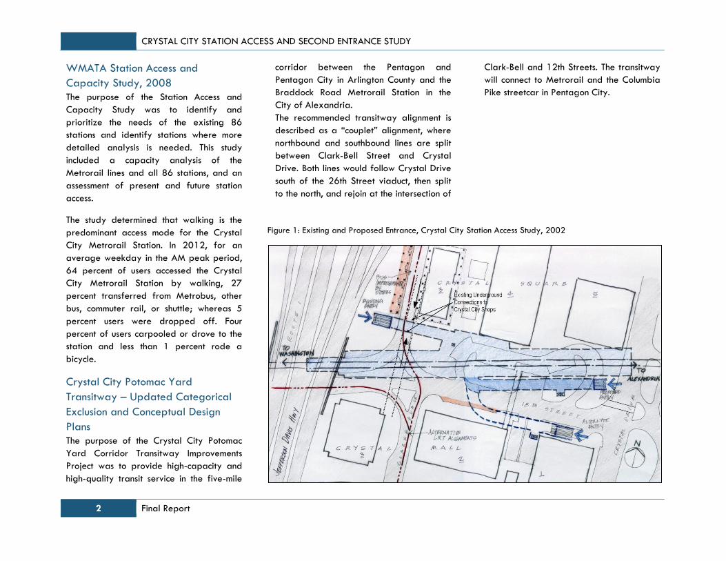
WMATA Crystal City Station Access
Study, 2002
The Crystal City Station Access Study was
conducted in 2002 and proposed station
access improvements including additional
station entrances and mezzanines,
improved traffic conditions on adjacent
streets, and improved connections between
Metrobus and Metrorail (see Figure 1).
Crystal City Sector Plan
In 2005, the Base Realignment and Closure
Commission’s (BRAC) recommendations
became federal law. The recommendations
call for the U.S. Department of Defense
(DoD) to relocate 17,000 jobs from
Arlington to nearby military bases. As part
of the County’s response to that
recommendation, the Crystal City Sector
Plan was recently approved by the County
Board and outlines a broad vision for
revitalization of the area in the next 40
years. This future vision for Crystal City will
help to guide change and is designed to
accommodate significant growth and
reinvestment. The Crystal City Sector Plan
offers a comprehensive vision for the future
of Crystal City, with an emphasis on
improving the quality of the public realm.
Crystal City Multimodal
Transportation Study
The Crystal City Multimodal Transportation
Study examines Crystal City’s
redevelopment in phases and proposes
transportation improvements to provide for
effective travel and mobility for the area’s
residents, workers and visitors through the
year 2050. This study covers all modes of
travel and provides physical and policy
recommendations for each of them,
consistent with goals and objectives of
Arlington County’s Master Transportation
Plan (MTP).
CRYSTAL CITY STATION ACCESS AND SECOND ENTRANCE STUDY
2 Final Report
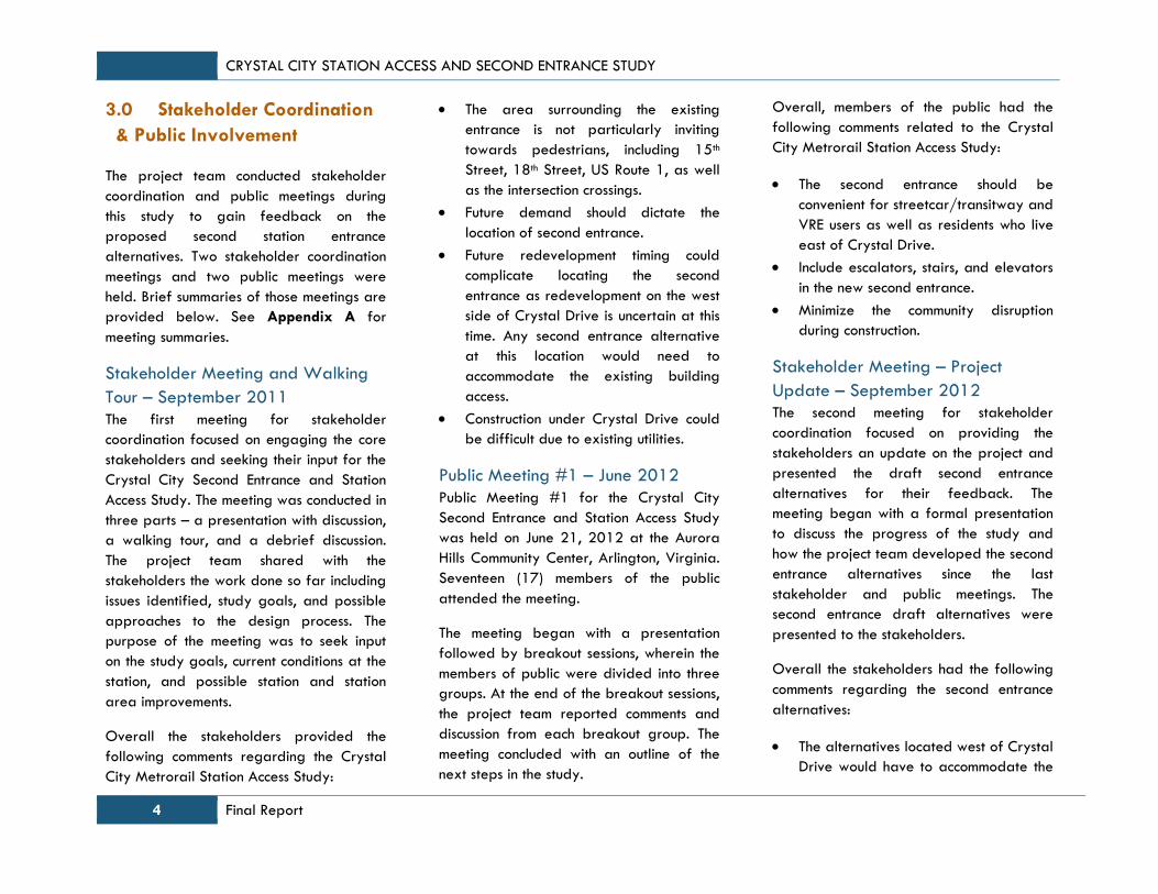
WMATA Station Access and
Capacity Study, 2008
The purpose of the Station Access and
Capacity Study was to identify and
prioritize the needs of the existing 86
stations and identify stations where more
detailed analysis is needed. This study
included a capacity analysis of the
Metrorail lines and all 86 stations, and an
assessment of present and future station
access.
The study determined that walking is the
predominant access mode for the Crystal
City Metrorail Station. In 2012, for an
average weekday in the AM peak period,
64 percent of users accessed the Crystal
City Metrorail Station by walking, 27
percent transferred from Metrobus, other
bus, commuter rail, or shuttle; whereas 5
percent users were dropped off. Four
percent of users carpooled or drove to the
station and less than 1 percent rode a
bicycle.
Crystal City Potomac Yard
Transitway – Updated Categorical
Exclusion and Conceptual Design
Plans
The purpose of the Crystal City Potomac
Yard Corridor Transitway Improvements
Project was to provide high-capacity and
high-quality transit service in the five-mile
corridor between the Pentagon and
Pentagon City in Arlington County and the
Braddock Road Metrorail Station in the
City of Alexandria.
The recommended transitway alignment is
described as a “couplet” alignment, where
northbound and southbound lines are split
between Clark-Bell Street and Crystal
Drive. Both lines would follow Crystal Drive
south of the 26th Street viaduct, then split
to the north, and rejoin at the intersection of
Clark-Bell and 12th Streets. The transitway
will connect to Metrorail and the Columbia
Pike streetcar in Pentagon City.
Figure 1: Existing and Proposed Entrance, Crystal City Station Access Study, 2002
CRYSTAL CITY STATION ACCESS AND SECOND ENTRANCE STUDY
Final Report 3
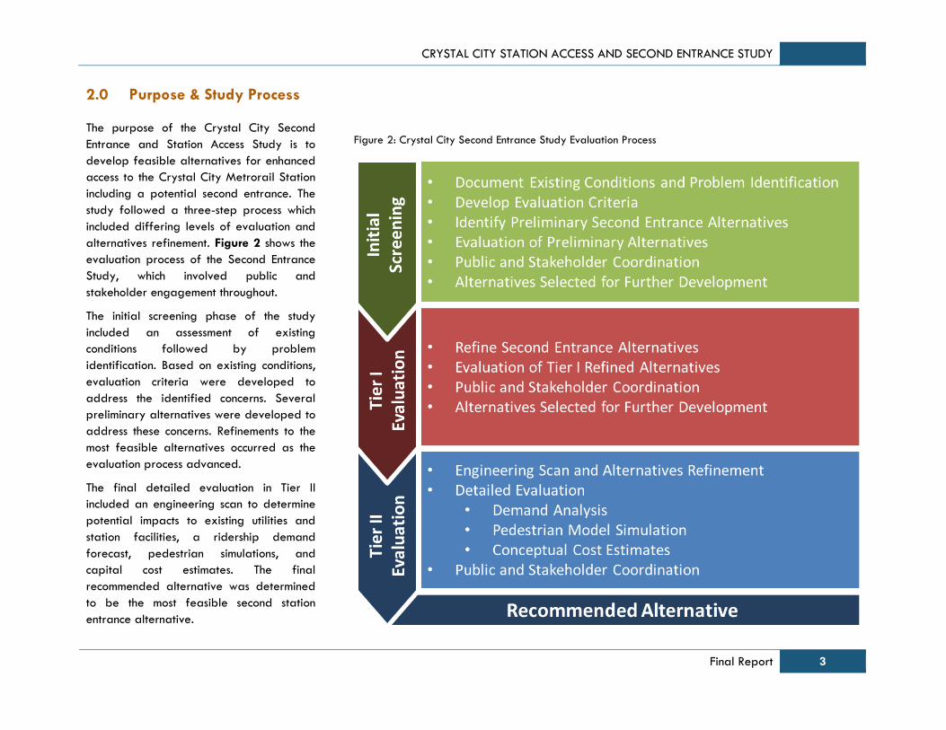
2.0 Purpose & Study Process
The purpose of the Crystal City Second
Entrance and Station Access Study is to
develop feasible alternatives for enhanced
access to the Crystal City Metrorail Station
including a potential second entrance. The
study followed a three-step process which
included differing levels of evaluation and
alternatives refinement. Figure 2 shows the
evaluation process of the Second Entrance
Study, which involved public and
stakeholder engagement throughout.
The initial screening phase of the study
included an assessment of existing
conditions followed by problem
identification. Based on existing conditions,
evaluation criteria were developed to
address the identified concerns. Several
preliminary alternatives were developed to
address these concerns. Refinements to the
most feasible alternatives occurred as the
evaluation process advanced.
The final detailed evaluation in Tier II
included an engineering scan to determine
potential impacts to existing utilities and
station facilities, a ridership demand
forecast, pedestrian simulations, and
capital cost estimates. The final
recommended alternative was determined
to be the most feasible second station
entrance alternative.
Figure 2: Crystal City Second Entrance Study Evaluation Process
CRYSTAL CITY STATION ACCESS AND SECOND ENTRANCE STUDY
4 Final Report
3.0 Stakeholder Coordination
& Public Involvement
The project team conducted stakeholder
coordination and public meetings during
this study to gain feedback on the
proposed second station entrance
alternatives. Two stakeholder coordination
meetings and two public meetings were
held. Brief summaries of those meetings are
provided below. See Appendix A for
meeting summaries.
Stakeholder Meeting and Walking
Tour – September 2011
The first meeting for stakeholder
coordination focused on engaging the core
stakeholders and seeking their input for the
Crystal City Second Entrance and Station
Access Study. The meeting was conducted in
three parts – a presentation with discussion,
a walking tour, and a debrief discussion.
The project team shared with the
stakeholders the work done so far including
issues identified, study goals, and possible
approaches to the design process. The
purpose of the meeting was to seek input
on the study goals, current conditions at the
station, and possible station and station
area improvements.
Overall the stakeholders provided the
following comments regarding the Crystal
City Metrorail Station Access Study:
The area surrounding the existing
entrance is not particularly inviting
towards pedestrians, including 15th
Street, 18th Street, US Route 1, as well
as the intersection crossings.
Future demand should dictate the
location of second entrance.
Future redevelopment timing could
complicate locating the second
entrance as redevelopment on the west
side of Crystal Drive is uncertain at this
time. Any second entrance alternative
at this location would need to
accommodate the existing building
access.
Construction under Crystal Drive could
be difficult due to existing utilities.
Public Meeting #1 – June 2012
Public Meeting #1 for the Crystal City
Second Entrance and Station Access Study
was held on June 21, 2012 at the Aurora
Hills Community Center, Arlington, Virginia.
Seventeen (17) members of the public
attended the meeting.
The meeting began with a presentation
followed by breakout sessions, wherein the
members of public were divided into three
groups. At the end of the breakout sessions,
the project team reported comments and
discussion from each breakout group. The
meeting concluded with an outline of the
next steps in the study.
Overall, members of the public had the
following comments related to the Crystal
City Metrorail Station Access Study:
The second entrance should be
convenient for streetcar/transitway and
VRE users as well as residents who live
east of Crystal Drive.
Include escalators, stairs, and elevators
in the new second entrance.
Minimize the community disruption
during construction.
Stakeholder Meeting – Project
Update – September 2012
The second meeting for stakeholder
coordination focused on providing the
stakeholders an update on the project and
presented the draft second entrance
alternatives for their feedback. The
meeting began with a formal presentation
to discuss the progress of the study and
how the project team developed the second
entrance alternatives since the last
stakeholder and public meetings. The
second entrance draft alternatives were
presented to the stakeholders.
Overall the stakeholders had the following
comments regarding the second entrance
alternatives:
The alternatives located west of Crystal
Drive would have to accommodate the
CRYSTAL CITY STATION ACCESS AND SECOND ENTRANCE STUDY
Final Report 5
existing building entrances and access
points as redevelopment of that block
would be in the 2030 year timeframe.
The alternatives located east of Crystal
Drive might orient towards the Water
Park and should be configured for
efficient access to and from the VRE
station.
The elevator alternative should explore
a potential ADA connection through the
existing Underground.
VRE Passenger and Crystal City
Day- and Lunch-Time Outreach
In addition to conducting two public
meetings and two stakeholder meetings, the
project team also held a separate outreach
event targeted at VRE passengers and
people in the Crystal City area during the
day-time and lunch-time hours. The
outreach consisted of handing out flyers
near the VRE platform during the morning
rush period (6:30 – 9:00 am) and a lunch
time information session in the
Underground. The flyer provided
information about the project and
proposed alternatives as well as
information about the upcoming public
meeting and a web address to access more
information and to submit comments. Project
team members were available to answer
questions about the project during these
two sessions.
Public Meeting #2 – October 2012
Public Meeting #2 for the Crystal City
Second Entrance & Station Access Study
was held October 3, 2012 at the Crystal
Park Condominiums Meeting Room located
at 1805 Crystal Drive, Arlington, Virginia.
Twenty eight (28) members of the public
attended the meeting.
The meeting began with an open house of
project materials followed by a
presentation. During the presentation, the
participants were encouraged to ask
questions about the project. The project
team noted the comments and discussion
from the public. The meeting concluded with
an outline of the next steps in the study.
Meeting participants noted the following
regarding the second entrance alternatives:
Some participants did not support any
alternative that encroached upon the
Water Park.
Elevator access from the east side of
Crystal Drive may be desirable to
assist those with mobility limitations.
Increased pedestrian traffic crossing
Crystal Drive should be a consideration
in placing a second station entrance.
Alternatives on the east side of Crystal
Drive could lead to sidewalk
congestion.
The second entrance alternative C
could consider direct access to the
existing Underground.
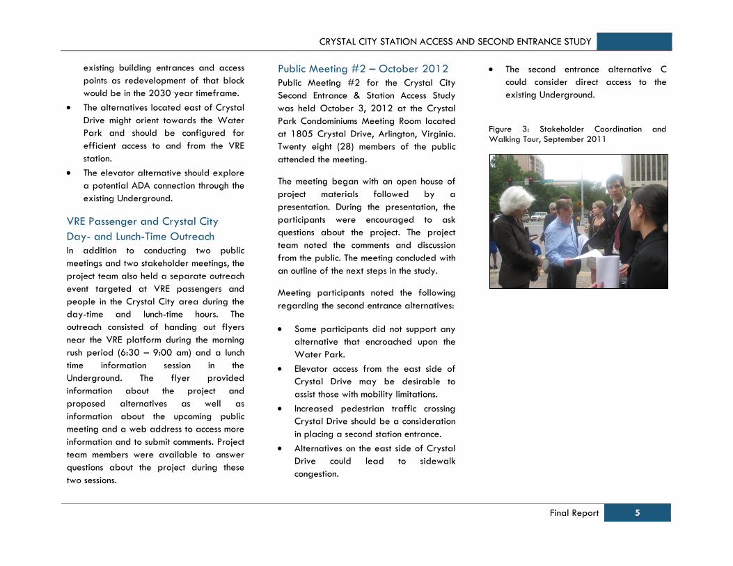
Figure 3: Stakeholder Coordination and
Walking Tour, September 2011
CRYSTAL CITY STATION ACCESS AND SECOND ENTRANCE STUDY
6 Final Report
4.0 Existing Station
Characteristics
General Description
The Crystal City Metrorail Station is located
on the Metrorail Blue and Yellow lines in
Crystal City, Arlington County, Virginia. The
Crystal City Metrorail Station has a single
entrance near the west end of the platform,
which is between Clark and Bell Streets, just
north of 18th Street South. The Metrorail
station is also accessible from the elevator
located just north of 18th Street South,
reached by a short pedestrian pathway.
Crystal City is also served by Virginia
Railway Express (VRE) - a commuter rail
service that connects the Northern Virginia
suburbs to Union Station in Washington,
D.C. The Crystal City VRE Station is located
within a close proximity of the Metrorail
Station entrance.
The Crystal City Metrorail Station is
surrounded by high density residential
buildings, office buildings and retail
development. The Ronald Reagan National
Airport (DCA) is located to the east of
Crystal City whereas the Pentagon lies
immediately to the north.
For purposes of capacity assessment, the
station area may be defined as the portion
of Crystal City within a quarter-mile radius
of the Crystal City Metrorail Station.
However, the Underground pedestrian
network extends the reach of the Metrorail
Station to include a larger area. Thus the
study area for the Crystal City Metrorail
Station extends from 12th Street in the
north to 26th Street in the south and
between the Jefferson Davis Highway on
the west and the CSX tracks on the east.
Therefore “east of Jefferson Davis
Highway” (mentioned in the Crystal City
Sector Plan) generally coincides with the
Crystal City Station Access Study Area.
Issues Identified
The following issues were identified by the
project team and coordination with the
public and relevant stakeholders at the
beginning of the process:
Existing Station Capacity Issues
o Station Usage
o Vertical Circulation
o Future Development
o VRE Ridership
Access and ADA Issues
Way-finding and Signage
Connections with Other Modes
Existing Station Capacity Issues
The Metrorail can accommodate the
projected growth in ridership. However, the
station facilities may become constrained
with the increasing number of Metrorail
users. The capacity of the existing station
was assessed based on the capacity of
station facilities – elevators, escalators, and
mezzanine and faregates compared to
future ridership growth.
Station Usage
Figure 4 and Figure 5 show typical
weekday entries and exits in 2013 from
the Crystal City station mezzanine.
Metrorail entries shown in the morning peak
(6:30AM to 9:30AM) in Figure 4 includes
Crystal City residents taking Metro to work
and approximately 720 VRE riders
transferring to Metro from the 13 AM trains
that stop at Crystal City. VRE riders make
up 13 percent of AM entries at the Crystal
City Metrorail Station. These groups are
shown returning home between 3:30 PM
and 7:00 PM in Figure 5. Conversely, the
AM peak in Figure 5 shows employees
coming to Crystal City (6:30AM to
9:30AM), who then leave between 3:30PM
and 6:30PM (Figure 4).

CRYSTAL CITY STATION ACCESS AND SECOND ENTRANCE STUDY
Final Report 7
Figure 4: Crystal City Metrorail Station - Entries to Mezzanine on a Typical Weekday in 2013
Source: WMATA Ridership Data, May 2013
Figure 5: Crystal City Metrorail Station - Exits From Mezzanine on a Typical Weekday in 2013
Source: WMATA Ridership Data, May 2013
0
100
200
300
400
500
600
700
800
900
10004:0
0 A
M
6:0
0 A
M
8:0
0 A
M
10:0
0 A
M
12:0
0 P
M
2:0
0 P
M
4:0
0 P
M
6:0
0 P
M
8:0
0 P
M
10:0
0 P
M
12:0
0 A
M
2:0
0 A
M
VRE Riders
Predominately
Residents
0
100
200
300
400
500
600
700
800
900
1,000
4:0
0 A
M
6:0
0 A
M
8:0
0 A
M
10:0
0 A
M
12:0
0 P
M
2:0
0 P
M
4:0
0 P
M
6:0
0 P
M
8:0
0 P
M
10:0
0 P
M
12:0
0 A
M
2:0
0 A
M
VRE Riders
Predominately Workers Predominately
Workers
Predominately Residents
CRYSTAL CITY STATION ACCESS AND SECOND ENTRANCE STUDY
8 Final Report
Vertical Circulation Capacity and
Utilization
Station capacity can be measured in
several locations, but generally the
capacity of vertical circulation elements
(escalators, stairs, and elevators) and fare
gates tend to be the two most important
components to measure for an in-line, non-
transfer station such as Crystal City.
As previously shown in Figures 4 and 5, the
most crowded station conditions can be
expected to occur during the AM peak
period. 2013 passenger counts found that
1,527 passengers combined to enter and
exit the station during the time period from
7:30 AM to 8:00 AM. Passenger demand
for the peak 15-minutes is assumed to be
60% of the peak half hour. The peak 15-
minute capacities and overall utilization of
each of vertical circulation elements are
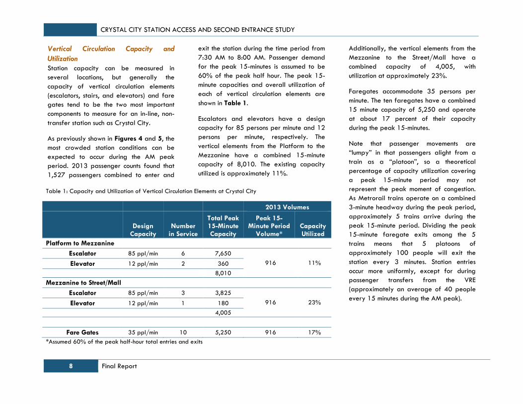
shown in Table 1.
Escalators and elevators have a design
capacity for 85 persons per minute and 12
persons per minute, respectively. The
vertical elements from the Platform to the
Mezzanine have a combined 15-minute
capacity of 8,010. The existing capacity
utilized is approximately 11%.
Additionally, the vertical elements from the
Mezzanine to the Street/Mall have a
combined capacity of 4,005, with
utilization at approximately 23%.
Faregates accommodate 35 persons per
minute. The ten faregates have a combined
15 minute capacity of 5,250 and operate
at about 17 percent of their capacity
during the peak 15-minutes.
Note that passenger movements are
“lumpy” in that passengers alight from a
train as a “platoon”, so a theoretical
percentage of capacity utilization covering
a peak 15-minute period may not
represent the peak moment of congestion.
As Metrorail trains operate on a combined
3-minute headway during the peak period,
approximately 5 trains arrive during the
peak 15-minute period. Dividing the peak
15-minute faregate exits among the 5
trains means that 5 platoons of
approximately 100 people will exit the
station every 3 minutes. Station entries
occur more uniformly, except for during
passenger transfers from the VRE
(approximately an average of 40 people
every 15 minutes during the AM peak).
Table 1: Capacity and Utilization of Vertical Circulation Elements at Crystal City
2013 Volumes
Design Capacity
Number in Service
Total Peak 15-Minute Capacity
Peak 15-Minute Period
Volume* Capacity Utilized
Platform to Mezzanine
Escalator 85 ppl/min 6 7,650
916 11% Elevator 12 ppl/min 2 360
8,010
Mezzanine to Street/Mall
Escalator 85 ppl/min 3 3,825
916 23% Elevator 12 ppl/min 1 180
4,005
Fare Gates 35 ppl/min 10 5,250 916 17%
*Assumed 60% of the peak half-hour total entries and exits
CRYSTAL CITY STATION ACCESS AND SECOND ENTRANCE STUDY
Final Report 9
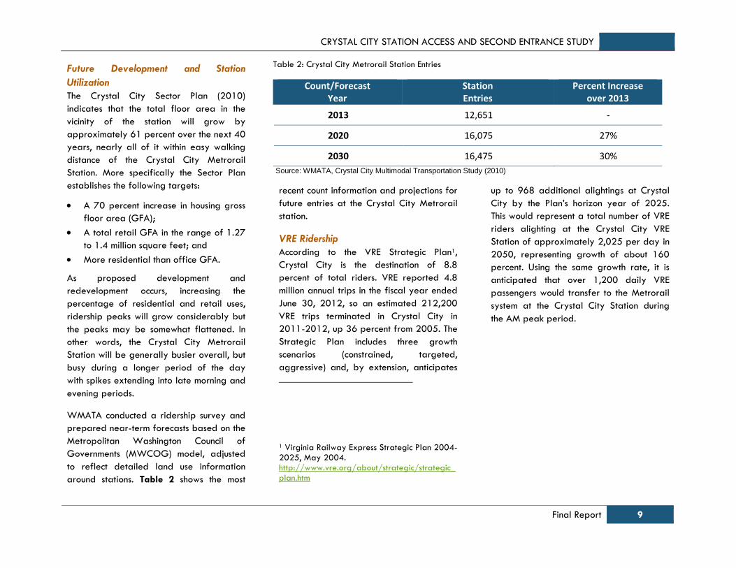
Table 2: Crystal City Metrorail Station Entries
Count/Forecast Year
Station Entries
Percent Increase over 2013
2013 12,651 -
2020 16,075 27%
2030 16,475 30%
Source: WMATA, Crystal City Multimodal Transportation Study (2010)
Future Development and Station
Utilization
The Crystal City Sector Plan (2010)
indicates that the total floor area in the
vicinity of the station will grow by
approximately 61 percent over the next 40
years, nearly all of it within easy walking
distance of the Crystal City Metrorail
Station. More specifically the Sector Plan
establishes the following targets:
A 70 percent increase in housing gross
floor area (GFA);
A total retail GFA in the range of 1.27
to 1.4 million square feet; and
More residential than office GFA.
As proposed development and
redevelopment occurs, increasing the
percentage of residential and retail uses,
ridership peaks will grow considerably but
the peaks may be somewhat flattened. In
other words, the Crystal City Metrorail
Station will be generally busier overall, but
busy during a longer period of the day
with spikes extending into late morning and
evening periods.
WMATA conducted a ridership survey and
prepared near-term forecasts based on the
Metropolitan Washington Council of
Governments (MWCOG) model, adjusted
to reflect detailed land use information
around stations. Table 2 shows the most
recent count information and projections for
future entries at the Crystal City Metrorail
station.
VRE Ridership
According to the VRE Strategic Plan1,
Crystal City is the destination of 8.8
percent of total riders. VRE reported 4.8
million annual trips in the fiscal year ended
June 30, 2012, so an estimated 212,200
VRE trips terminated in Crystal City in
2011-2012, up 36 percent from 2005. The
Strategic Plan includes three growth
scenarios (constrained, targeted,
aggressive) and, by extension, anticipates
1 Virginia Railway Express Strategic Plan 2004-2025, May 2004. http://www.vre.org/about/strategic/strategic_plan.htm
up to 968 additional alightings at Crystal
City by the Plan’s horizon year of 2025.
This would represent a total number of VRE
riders alighting at the Crystal City VRE
Station of approximately 2,025 per day in
2050, representing growth of about 160
percent. Using the same growth rate, it is
anticipated that over 1,200 daily VRE
passengers would transfer to the Metrorail
system at the Crystal City Station during
the AM peak period.

CRYSTAL CITY STATION ACCESS AND SECOND ENTRANCE STUDY
10 Final Report
Access Issues
The focus of access issues was not limited to
ADA (Americans with Disabilities Act of
1990) accessibility concerns but also
included the ease and directness of route,
pedestrian comfort and minimal conflict
between automobiles and pedestrians. The
access issues were assessed by observing
the elevators, pedestrian facilities and
stairs along the access path to the Metrorail
Station. These are discussed as follows:
Elevators – There is one elevator
located off of 18th Street South
connecting street level to the
mezzanine. The elevator is obscured by
bushes and the path to the elevator is
neither straight nor easily accessible.
Pedestrian Facilities – 18th Street South
is the shortest and most direct
connection from Crystal Drive to the
Metrorail Station entrance. Although
there are sidewalks on both sides of
the road, they are interrupted with
driveways and delivery entrances,
leading to auto-pedestrian conflicts
and safety concerns.
Stairs and Steps – The route to the
Metrorail station from the VRE via the
Underground is climate-controlled, but
it is indirect and involves multiple sets
of stairs, making it an inconvenient
choice, particularly for passengers with
mobility challenges.
Way-finding and Signage
The following observations were made
regarding way-finding and signage in the
vicinity of the Crystal City Metrorail
Station:
There are many signs guiding users to
the Metrorail Station, the Crystal City
shops, and the VRE station. There are
signs directing users to the accessible
entrances to the Crystal City shops and
the Metrorail station. However, the
directions are not straightforward or
intuitive and there is a lack of visual
continuity which may be confusing for
new visitors.
The sign directing users to the
accessible station entrance is too high
for easy legibility by a person in a
wheelchair. The sign says S. Clark
Street, whereas it should say 18th
Street S. Similar sign(s) are missing on
the east side of the entrance.
CRYSTAL CITY STATION ACCESS AND SECOND ENTRANCE STUDY
Final Report 11
Connections with Other Modes
The Crystal City Sector Plan aims to
strengthen Crystal City’s position as a truly
multimodal community. Improved
connections and enhanced signage
directing users to other modes can be
beneficial in achieving this objective.
Connections with other modes were
assessed by observing bicycle parking,
Metrobus stops and commuter rail
connections. Lack of Kiss & Ride locations
was also noted. These are discussed below:
Capital Bikeshare
There are four Capital Bikeshare stations
within 1/4-mile of the existing station
entrance that provide bicycles on a daily,
monthly, or annual membership basis. There
are no signs directing passengers to the
locations of the Capital Bikeshare stations.
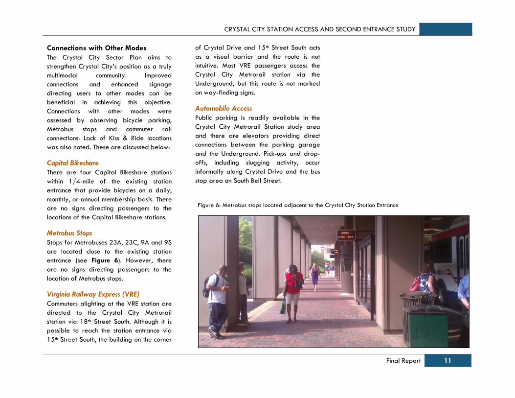
Metrobus Stops
Stops for Metrobuses 23A, 23C, 9A and 9S
are located close to the existing station
entrance (see Figure 6). However, there
are no signs directing passengers to the
location of Metrobus stops.
Virginia Railway Express (VRE)
Commuters alighting at the VRE station are
directed to the Crystal City Metrorail
station via 18th Street South. Although it is
possible to reach the station entrance via
15th Street South, the building on the corner
of Crystal Drive and 15th Street South acts
as a visual barrier and the route is not
intuitive. Most VRE passengers access the
Crystal City Metrorail station via the
Underground, but this route is not marked
on way-finding signs.
Automobile Access
Public parking is readily available in the
Crystal City Metrorail Station study area
and there are elevators providing direct
connections between the parking garage
and the Underground. Pick-ups and drop-
offs, including slugging activity, occur
informally along Crystal Drive and the bus
stop area on South Bell Street.
Figure 6: Metrobus stops located adjacent to the Crystal City Station Entrance

CRYSTAL CITY STATION ACCESS AND SECOND ENTRANCE STUDY
12 Final Report
5.0 Alternatives Development
and Initial Screening
The alternatives development and initial
screening was the first step in the
evaluation process. Based on the existing
conditions, the evaluation criteria were
developed to address the identified
concerns. Several alternatives were
developed and screened through a public
and stakeholder coordination process. The
feedback obtained from these coordination
efforts was incorporated into the
alternatives development and evaluation
process.
5.1. Initial Screening Evaluation
Criteria
The alternatives for improving station
access and the alternatives for a second
entrance to the Crystal City Metrorail
Station were evaluated and compared
using the criteria and stakeholder goals
defined below:
Improve access from east;
Improve access for special needs users ;
Improve multimodal connectivity
(bicycles, transitway, commuter buses);
Integrate with proposed
redevelopment & reinvestment;
Address long-term growth in ridership
(including station facilities, faregates,
elevators and escalators);
Environmental and community impacts;
Constructability; and
Safety – mobility and ease of
evacuation.
Improve access from Crystal Drive - A
large number of Metrorail users access the
Crystal City Metrorail Station from the
direction of Crystal Drive, and many of
them transfer between Virginia Railway
Express (VRE) station and the Crystal City
Metrorail Station. An additional entrance
would better serve the needs of users
accessing the station from the direction of
Crystal Drive. Alternatives creating station
access east of Crystal Drive would be rated
more highly than alternatives creating
station access west of Crystal Drive, which
in turn would be rated more highly than
alternatives that do not create station
access or improve access far from Crystal
Drive.
Improve multimodal connectivity - The
station should be safely and comfortably
accessible by all modes of transport. The
ideal station area would include ample
sidewalks with clearly marked pedestrian
crossings that follow desire lines, a
connected network of bicycle routes and
secure bicycle parking, easy transfers to
existing and future surface transit
connections, and clear signage directing
users from one mode to another.
Alternatives that provide enhanced bus
stop capacity would be rated more highly.
Alternatives that provide ample space for
nearby bicycle parking would also be
rated more highly.
Improve access for special needs users -
The station should be easily accessible by
all users including those with special needs
(elderly, disabled, people with luggage or
strollers etc.) Alternatives that increase
elevator capacity, reliability, redundancy,
and ease of use and that enhance
accessible routes to the station would be
rated more highly.
Integrate with proposed redevelopment &
reinvestment - The future vision for Crystal
City is for significant growth and
reinvestment. The ideal station entrance will
integrate well with proposed and planned
development and redevelopment.
Alternatives that can be integrated into
redevelopment would be rated more highly
than alternatives that interfere with
planned redevelopment. Additionally, the
Crystal City Sector Plan calls for a new
“Metro Market Square” park near the
proposed second entrance alternatives. The
study team took the planned space into
consideration in the development of the
alternatives.
CRYSTAL CITY STATION ACCESS AND SECOND ENTRANCE STUDY
Final Report 13
Address long-term growth in ridership - The
ideal station entrance will have sufficient
capacity at faregates, escalators,
elevators, platforms and mezzanine to
facilitate easy movement of users.
Alternatives that enhance capacity of all
station elements to address long-term
ridership growth would be rated more
highly than alternatives that address fewer
or no station elements.
Environmental and community impacts - The
Crystal City Sector Plan offers a
comprehensive vision for the future of the
Crystal City, with an emphasis on improving
the quality of the public realm. The ideal
station entrance would enhance existing
and new environmental features, without
adverse impacts to the surrounding area.
Alternatives that do not impact or that
create benefits to water quality, wetlands,
floodplains, air quality, hazardous
materials, noise, and vibration would be
rated more highly. The Crystal City Sector
Plan places an emphasis on improving the
quality of the public realm. The ideal
station entrance would enhance existing
and new public facilities such as parks,
plazas etc. while providing opportunities
for new retail and other private sector
benefits. Alternatives with fewer impacts on
right-of-way acquisition, community
disruption, environmental justice
communities, parklands and open space,
and traffic would be rated more highly.
Constructability - The construction of a new
station entrance may result in conflicts with
existing infrastructure requiring the
relocation of underground structures and
utilities. Construction of the new station
entrance may require cutting through the
existing tunnel vault, which has significant
cost implications. A new station entrance
that minimizes impacts on existing
infrastructure would be rated more highly.
Alternatives with less conflict with utilities or
underground structures would be rated
more highly. Alternatives that have a lower
impact on the streetcar trackway would be
rated more highly.
Safety (mobility, evacuation etc.) - The new
station entrance should have sufficient
capacity for all users at all times to
minimize conflicts and crowding; and
provide clear routes for egress. Alternatives
that enhance emergency egress from the
station – by providing redundant egress
routes or reduce evacuation time – would
be rated more highly.

CRYSTAL CITY STATION ACCESS AND SECOND ENTRANCE STUDY
14 Final Report
5.2. Alternatives Identified
Several alternatives have been identified
that can improve access to the Crystal City
Metrorail Station. Some alternatives may
be low-cost or short-term improvements that
help users better navigate the station area,
and some alternatives are higher cost and
include more substantial improvements
including elevators, ADA ramps and a new
second entrance to the Metrorail station.
The alternatives that were identified can be
classified into three distinct categories.
These are described below:
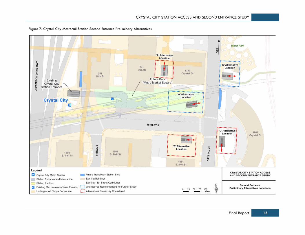
Second Entrance Alternatives
There are five alternatives in this category.
These are described below and are shown
in Figure 7.
Alternative A: Northwest corner of 18th
Street and Crystal Drive; could connect to
elevator bank along 18th Street (Short-Term
Elevator Alternative “C”) [Recommendation
from 2002 Access Study].
Alternative B: Southwest corner of 18th
Street and Crystal Drive; could be a part
of future development or add a below-
ground connection to mezzanine; could
connect to Second Entrance Alternative “A”.
Alternative C: Full entrance to connect to
new mezzanine on the east side of Crystal
Drive, north of future transitway stop.
Alternative D: Full entrance to connect to
new mezzanine on the east side of Crystal
Drive, south of future transitway stop.
Alternative E: Full entrance to connect
from the existing Underground shopping
mall (north side) to the existing mezzanine
through a new passageway.
Initial Access Improvements –
Improved way-finding and signage,
and intersection improvements
The various elements of this alternative are
described below and are shown in
Figure 8.
Improve pedestrian experience
underneath US Route 1. Relocate
shuttle bus boardings and alightings to
this area.
Improve way-finding and signage at
the Underground crossing and the
station entrance passage.
Improve signage and visibility of
existing elevator.
Improve ADA access to existing
elevator from surface parking lot.
Improve pedestrian crossings at
intersections in the vicinity of the
Metrorail station entrance.
Elevator Improvement Alternatives
There is only one existing elevator between
the street and the mezzanine level. In the
event that this elevator is broken or under
maintenance, there is no ADA access to the
station. Therefore it was recommended that
the project team analyze an elevator only
option for station entrance. This may also
be used as an interim solution until the time
a long term high capacity entrance is
designed and built. There are four
alternatives in this category. Because an
elevator option is not considered adequate
to handle future rider volumes, these
alternatives were not evaluated in detail.
They are described and shown in
Appendix B.
CRYSTAL CITY STATION ACCESS AND SECOND ENTRANCE STUDY
Final Report 15
Figure 7: Crystal City Metrorail Station Second Entrance Preliminary Alternatives

CRYSTAL CITY STATION ACCESS AND SECOND ENTRANCE STUDY
16 Final Report
Figure 8: Crystal City Metrorail Station - Initial Access Alternative
CRYSTAL CITY STATION ACCESS AND SECOND ENTRANCE STUDY
Final Report 17
5.3. Evaluation of Preliminary
Alternatives
The evaluation of preliminary alternatives
followed a two-step process. In the first
phase of evaluation, an initial screening of
all alternatives was conducted using the
evaluation criteria identified in Section 5.1.
This initial screening was conducted for all
alternatives except the Initial Access
Improvement alternative. Second Entrance
Alternatives A and C were advanced for
further consideration and development,
whereas Alternatives B, D and E received
lower ratings and were not analyzed
further. Elevator alternatives were not
considered sufficient to handle future rider
volumes and were not analyzed in this
phase. The detailed analysis for Second
Entrance Alternatives is summarized in the
Evaluation Matrix in Appendix C.
Alternative A performs very well against
most evaluation criteria. Alternative A
improves access from Crystal Drive and
significantly improves the visibility of the
station. It also improves capacity, relieves
congestion, and has community benefits.
Depending upon the exact configuration of
the new mezzanine and faregates etc.,
Alternative A may involve reconfiguring of
the existing station service rooms.
Alternative A improves multimodal
connectivity and has no impacts to the
proposed private development.
Alternative B has some noteworthy
drawbacks. It requires significant
coordination with proposed private
development. Alternative B would also
require cutting through the tunnel vault of
the existing station, and the construction of
a long tunnel.
Alternative C has several significant
benefits. Its location makes it very
convenient for VRE users, the Mount Vernon
trail and the proposed transitway/streetcar
stops. While it would involve reconfiguring
the existing station service rooms in the
existing station, a new entrance in
Alternative C would include significant
improvements to the station facilities, would
reduce congestion, and improve mobility.
Alternative D would have some impacts to
proposed private development without
significant community benefits. It would also
entail reconfiguring service rooms in the
existing station, and would have significant
impacts to utilities under Crystal Drive.
Alternative E received an unfavorable
rating primarily because of its location in
the Underground. Alternative E location
would not be visible from the street,
thereby limiting multimodal access. It would
also impact Underground retail activities
and would not add any capacity to the
station facilities.
As a result of the initial screening, the
second entrance alternatives that received
a lower rating (Alternative B, D, and E)
were screened out and those alternatives
that received the highest ratings were
considered most feasible and advanced for
further refinement (Alternatives A and C).
CRYSTAL CITY STATION ACCESS AND SECOND ENTRANCE STUDY
18 Final Report
6.0 Tier I Alternatives
Refinement and Evaluation
Alternatives A and C were developed
further and design improvements were
made. The project team ensured that each
alternative met the WMATA guidelines for
ADA access, and that elevators are
provided in pairs for redundancy.
In the process of refinement, the project
team considered different orientations for
the escalators at the new station entrance;
discussed locating the mezzanine and
faregates at the street level; and also
refined the alternatives for ensuring smooth
flow of passengers both on the surface as
well as on the station platform, in an effort
to improve circulation and minimize
congestion. During this design development,
the project moved from conceptual
alternatives to feasible alternatives. As a
result of this refinement process, the new
alternatives A.1, A.2, and C.1 emerged.
Figure 9 shows the general location of
Second Entrance “A” Alternatives, whereas
Figure 10 shows the general location of
Second Entrance “C” Alternatives. The Tier
I Refined Alternatives can be found in
Appendix D.
The refined Second Entrance Alternatives
for Tier I Evaluation are as follows:
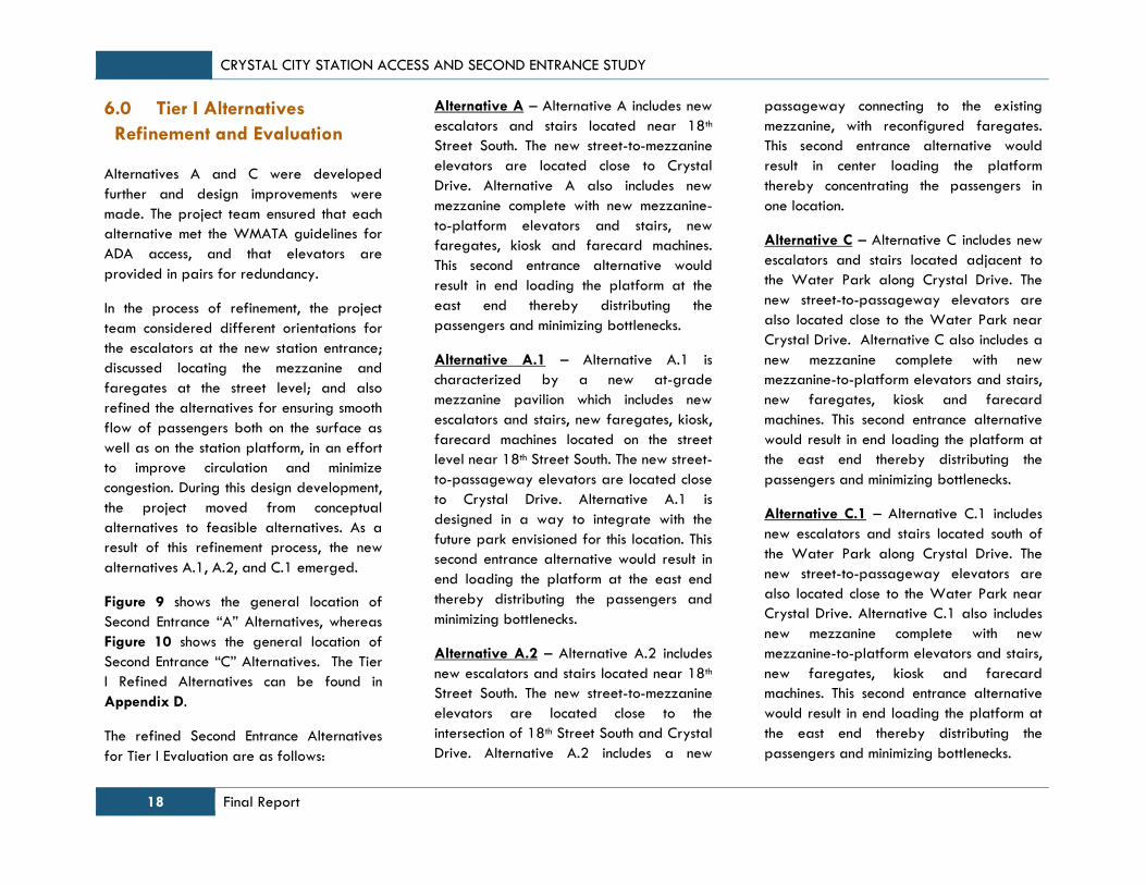
Alternative A – Alternative A includes new
escalators and stairs located near 18th
Street South. The new street-to-mezzanine
elevators are located close to Crystal
Drive. Alternative A also includes new
mezzanine complete with new mezzanine-
to-platform elevators and stairs, new
faregates, kiosk and farecard machines.
This second entrance alternative would
result in end loading the platform at the
east end thereby distributing the
passengers and minimizing bottlenecks.
Alternative A.1 – Alternative A.1 is
characterized by a new at-grade
mezzanine pavilion which includes new
escalators and stairs, new faregates, kiosk,
farecard machines located on the street
level near 18th Street South. The new street-
to-passageway elevators are located close
to Crystal Drive. Alternative A.1 is
designed in a way to integrate with the
future park envisioned for this location. This
second entrance alternative would result in
end loading the platform at the east end
thereby distributing the passengers and
minimizing bottlenecks.
Alternative A.2 – Alternative A.2 includes
new escalators and stairs located near 18th
Street South. The new street-to-mezzanine
elevators are located close to the
intersection of 18th Street South and Crystal
Drive. Alternative A.2 includes a new
passageway connecting to the existing
mezzanine, with reconfigured faregates.
This second entrance alternative would
result in center loading the platform
thereby concentrating the passengers in
one location.
Alternative C – Alternative C includes new
escalators and stairs located adjacent to
the Water Park along Crystal Drive. The
new street-to-passageway elevators are
also located close to the Water Park near
Crystal Drive. Alternative C also includes a
new mezzanine complete with new
mezzanine-to-platform elevators and stairs,
new faregates, kiosk and farecard
machines. This second entrance alternative
would result in end loading the platform at
the east end thereby distributing the
passengers and minimizing bottlenecks.
Alternative C.1 – Alternative C.1 includes
new escalators and stairs located south of
the Water Park along Crystal Drive. The
new street-to-passageway elevators are
also located close to the Water Park near
Crystal Drive. Alternative C.1 also includes
new mezzanine complete with new
mezzanine-to-platform elevators and stairs,
new faregates, kiosk and farecard
machines. This second entrance alternative
would result in end loading the platform at
the east end thereby distributing the
passengers and minimizing bottlenecks.

CRYSTAL CITY STATION ACCESS AND SECOND ENTRANCE STUDY
Final Report 19
A, A.1, and A.2 Alternatives
A, A.1, and A.2 Alternatives
Figure 9: Crystal City Metrorail Station Second Entrance “A” Alternatives Location
CRYSTAL CITY STATION ACCESS AND SECOND ENTRANCE STUDY
20 Final Report
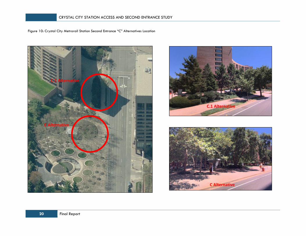
C Alternative
C.1 Alternative
Figure 10: Crystal City Metrorail Station Second Entrance “C” Alternatives Location
C Alternative
C.1 Alternative

CRYSTAL CITY STATION ACCESS AND SECOND ENTRANCE STUDY
Final Report 21
6.1 Tier I Evaluation of Refined
Second Entrance Alternatives
Each of the refined Second Entrance
alternatives - A, A.1, A.2, C, and C.1- was
designed to address safety and mobility
concerns. All alternatives improve the
visibility of the station entrance, thereby
improving multimodal access. They also
follow ADA accessibility guidelines. Each
one of these alternatives has minimal
impacts to the proposed private
development and reasonable benefits to
the community. Since each refined
alternative is a product of the evaluation
criteria from the initial screening, the Tier I
evaluation process focuses mainly on the
differences between them. As a result the
Tier I evaluation criteria include a shorter
list, comprising four elements, which are
discussed below:
Access for all – This criterion focuses on the
ability of the new entrance to provide
improved access for all users, including
those who may access the station from VRE
and Crystal Drive. Although all alternatives
provide multimodal access, the proximity to
future transitway stops, Mount Vernon Trail
and Metrobus stops is considered
favorable. The pros and cons of each
alternative with regard to Access are
summarized in Table 3.
Capacity for future growth – The Crystal
City Sector Plan envisions a significant
amount of development and redevelopment
in Crystal City which will bring new
residents, employees and visitors to the
area. Therefore the Crystal City Metrorail
Station should have enough capacity to
serve the future ridership. An alternative
that provides another way of accessing the
trains at the Metrorail station to disperse
the passengers will be considered more
favorable with regards to this project goal.
If the new entrance includes new station
facilities (escalators, elevators, stairs,
faregates, farecard machines etc.) then the
alternative would have significant benefits
with regards to accommodating future
growth and ridership. Table 4 summarizes
the pros and cons of each alternative with
regard to capacity to accommodate future
growth.
Constructability – There are several factors
that determine the cost of an alternative. In
general, if an alternative is difficult to
construct, it will be more expensive to build.
Some of the constructability issues in this
study occur from relocation of existing
station facilities such as elevator machine
rooms, vent shafts and service rooms. In
some cases, the alternative may require
cutting through the tunnel vault of the
existing station, which will add to the cost
of construction. Any alternative that includes
a tunnel under Crystal Drive would impact
the existing utility lines, with associated
costs. These constructability issues are
summarized in Table 5.
Contribution to the public realm – A new
station entrance has the potential to
enhance the community benefits, serve as a
landmark in the area and add to street life.
Similarly, an alternative may adversely
affect community resources and not blend
well with the existing surroundings. An
alternative that blends well with the
surroundings and contributes to the public
realm will be considered favorable. Table
6 summarizes the pros and cons of each
alternative with regard to contribution to
the public realm.

CRYSTAL CITY STATION ACCESS AND SECOND ENTRANCE STUDY
22 Final Report
Table 3: Access for All - Pros and Cons of Refined Second Entrance Alternatives
Alternatives
Access for All
Pros Cons
A
Improves ADA and general access from Crystal Drive
Improves multimodal access
Requires crossing Crystal Drive from the east
Escalator is not oriented towards the east
A.1
Improves ADA and general access from Crystal Drive
Improves multimodal access
The pavilion increases the visibility of the station
Requires crossing Crystal Drive from the east
Escalator is not oriented towards the east
A.2
Improves ADA and general access from Crystal Drive
Improves multimodal access
Escalator oriented toward Crystal Drive
Requires crossing Crystal Drive from the east
Long tunnel from surface opening to mezzanine
C
Improves ADA and general access from the East side of Crystal Drive
Improves multimodal access
May constrain sidewalk width on the east side of Crystal Drive
C.1
Improves ADA and general access from the East side of Crystal Drive
Improves multimodal access
May constrain sidewalk width on the east side of Crystal Drive
In general, Alternatives C and C.1 provide improved access to users on the east side of Crystal Drive (VRE riders and residents east of Crystal
Drive). Alternatives A and A.1 provide improved access, however, still require users to cross Crystal Drive, which may be a deterrent to some users.
Alternative A.2 includes a long tunnel which may be problematic for users with impaired mobility.
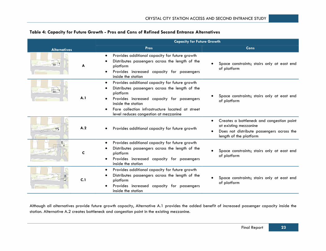
CRYSTAL CITY STATION ACCESS AND SECOND ENTRANCE STUDY
Final Report 23
Table 4: Capacity for Future Growth - Pros and Cons of Refined Second Entrance Alternatives
Alternatives
Capacity for Future Growth
Pros Cons
A
Provides additional capacity for future growth
Distributes passengers across the length of the platform
Provides increased capacity for passengers inside the station
Space constraints; stairs only at east end of platform
A.1
Provides additional capacity for future growth
Distributes passengers across the length of the platform
Provides increased capacity for passengers inside the station
Fare collection infrastructure located at street level reduces congestion at mezzanine
Space constraints; stairs only at east end of platform
A.2 Provides additional capacity for future growth
Creates a bottleneck and congestion point at existing mezzanine
Does not distribute passengers across the length of the platform
C
Provides additional capacity for future growth
Distributes passengers across the length of the platform
Provides increased capacity for passengers inside the station
Space constraints; stairs only at east end of platform
C.1
Provides additional capacity for future growth
Distributes passengers across the length of the platform
Provides increased capacity for passengers inside the station
Space constraints; stairs only at east end of platform
Although all alternatives provide future growth capacity, Alternative A.1 provides the added benefit of increased passenger capacity inside the
station. Alternative A.2 creates bottleneck and congestion point in the existing mezzanine.

CRYSTAL CITY STATION ACCESS AND SECOND ENTRANCE STUDY
24 Final Report
Table 5: Constructability - Key Cost Drivers for Refined Second Entrance Alternatives
Alternatives
Constructability
Key Cost Drivers
A
Requires cutting through the end wall of the station tunnel
Requires reconfiguration of surface vehicular building access
Requires relocation of station vents and mechanical rooms
A.1
Requires cutting through the end wall of the station tunnel
Requires reconfiguration of surface vehicular building access
Requires relocation of the station vents and mechanical rooms
A.2 Requires cutting through station tunnel vault
Requires the construction of a long passageway
C
Requires cutting through the end wall of the station tunnel
Requires reconfiguration of surface vehicular building access
Requires long passageway with impacts to utilities under Crystal Drive
Will cause traffic disruptions for Crystal Drive during construction
C.1
Requires cutting through the end wall of the station tunnel
Requires reconfiguration of surface vehicular building access
Requires long passageway with impacts to utilities under Crystal Drive
Will cause traffic disruptions for Crystal Drive during construction
All alternatives will requires cutting through the end wall of the station tunnel with the exception of Alternative A.2 which requires cutting through the
station tunnel vault. Alternatives A and A.1 will also require relocation of station vents and mechanical rooms. Alternatives C and C.1 will impact
utilities under Crystal Drive and cause traffic disruptions for Crystal Drive during construction.
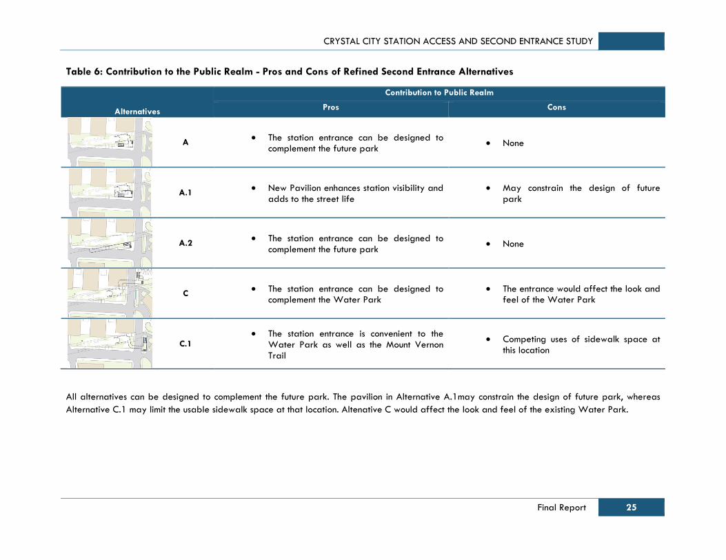
CRYSTAL CITY STATION ACCESS AND SECOND ENTRANCE STUDY
Final Report 25
Table 6: Contribution to the Public Realm - Pros and Cons of Refined Second Entrance Alternatives
Alternatives
Contribution to Public Realm
Pros Cons
A The station entrance can be designed to
complement the future park None
A.1 New Pavilion enhances station visibility and
adds to the street life May constrain the design of future
park
A.2 The station entrance can be designed to
complement the future park None
C The station entrance can be designed to
complement the Water Park The entrance would affect the look and
feel of the Water Park
C.1 The station entrance is convenient to the
Water Park as well as the Mount Vernon Trail
Competing uses of sidewalk space at this location
All alternatives can be designed to complement the future park. The pavilion in Alternative A.1may constrain the design of future park, whereas
Alternative C.1 may limit the usable sidewalk space at that location. Altenative C would affect the look and feel of the existing Water Park.
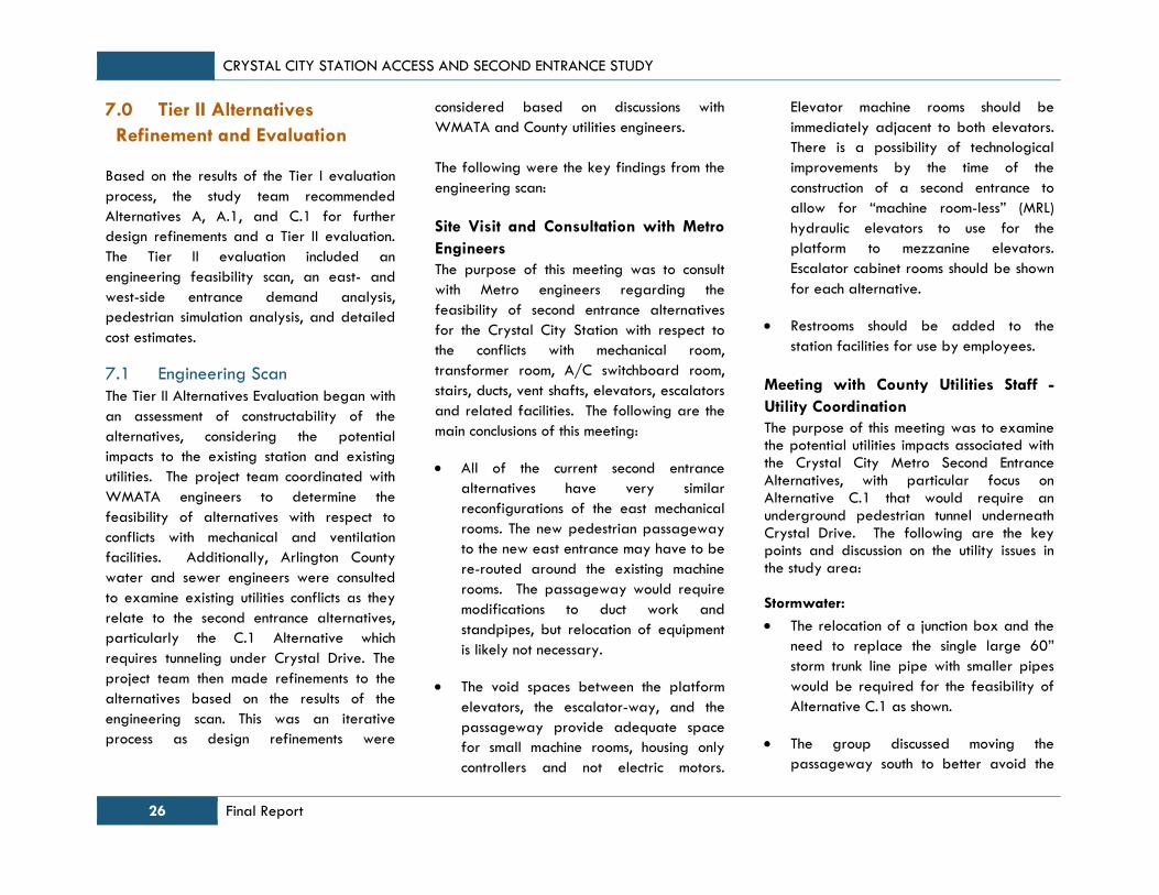
CRYSTAL CITY STATION ACCESS AND SECOND ENTRANCE STUDY
26 Final Report
7.0 Tier II Alternatives
Refinement and Evaluation
Based on the results of the Tier I evaluation
process, the study team recommended
Alternatives A, A.1, and C.1 for further
design refinements and a Tier II evaluation.
The Tier II evaluation included an
engineering feasibility scan, an east- and
west-side entrance demand analysis,
pedestrian simulation analysis, and detailed
cost estimates.
7.1 Engineering Scan
The Tier II Alternatives Evaluation began with
an assessment of constructability of the
alternatives, considering the potential
impacts to the existing station and existing
utilities. The project team coordinated with
WMATA engineers to determine the
feasibility of alternatives with respect to
conflicts with mechanical and ventilation
facilities. Additionally, Arlington County
water and sewer engineers were consulted
to examine existing utilities conflicts as they
relate to the second entrance alternatives,
particularly the C.1 Alternative which
requires tunneling under Crystal Drive. The
project team then made refinements to the
alternatives based on the results of the
engineering scan. This was an iterative
process as design refinements were
considered based on discussions with
WMATA and County utilities engineers.
The following were the key findings from the
engineering scan:
Site Visit and Consultation with Metro
Engineers
The purpose of this meeting was to consult
with Metro engineers regarding the
feasibility of second entrance alternatives
for the Crystal City Station with respect to
the conflicts with mechanical room,
transformer room, A/C switchboard room,
stairs, ducts, vent shafts, elevators, escalators
and related facilities. The following are the
main conclusions of this meeting:
All of the current second entrance
alternatives have very similar
reconfigurations of the east mechanical
rooms. The new pedestrian passageway
to the new east entrance may have to be
re-routed around the existing machine
rooms. The passageway would require
modifications to duct work and
standpipes, but relocation of equipment
is likely not necessary.
The void spaces between the platform
elevators, the escalator-way, and the
passageway provide adequate space
for small machine rooms, housing only
controllers and not electric motors.
Elevator machine rooms should be
immediately adjacent to both elevators.
There is a possibility of technological
improvements by the time of the
construction of a second entrance to
allow for “machine room-less” (MRL)
hydraulic elevators to use for the
platform to mezzanine elevators.
Escalator cabinet rooms should be shown
for each alternative.
Restrooms should be added to the
station facilities for use by employees.
Meeting with County Utilities Staff -
Utility Coordination
The purpose of this meeting was to examine the potential utilities impacts associated with the Crystal City Metro Second Entrance Alternatives, with particular focus on Alternative C.1 that would require an underground pedestrian tunnel underneath Crystal Drive. The following are the key points and discussion on the utility issues in the study area: Stormwater:
The relocation of a junction box and the
need to replace the single large 60”
storm trunk line pipe with smaller pipes
would be required for the feasibility of
Alternative C.1 as shown.
The group discussed moving the
passageway south to better avoid the

CRYSTAL CITY STATION ACCESS AND SECOND ENTRANCE STUDY
Final Report 27
storm junction structure. The group also
discussed whether the passageway could
be lowered rather than modifying the
storm sewer. It was decided that the
tunnel would be designed at a lower
depth to avoid the stormwater junction
structure.
Additional coordination with Arlington
County utility engineers would be
required on the feasibility of resizing or
modifying the 60” storm trunk line
pending a selection of a preferred
alternative and future design phases.
Electrical Utilities:
Electrical utilities would be difficult to
move and relocate.
The study team initiated consultation with
PEPCO on the electric transmission lines
underneath Crystal Drive and received
additional information on the existing
electrical facilities in the study area.
Additional coordination should occur
pending a selection of a preferred
alternative and future design phases.
Gas Utilities:
Gas lines are flexible and are relatively
easy to relocate.
Sanitary Utilities:
The existing sanitary lines use asbestos
cement, creating an environmental and
safety hazard if required to be moved.
Traffic and Street Lights:
Traffic and street lighting would have
conflicts, but relocation is not an issue.
Unknown Utilities:
Given the proximity to the Pentagon and
the number of secure Department of
Defense contractors in the study area,
there may be unknown facilities such as
fiber optic cables that may present
conflicts with the design concepts.
Constructability:
The “A” Alternatives are more ideal for
constructability compared to Alternative
C.1.
There would be potential difficulties in
maintaining access to existing buildings
and parking during construction for all
alternatives.
Maintenance of Traffic would be
substantial as the study area is in a
highly active urban environment.
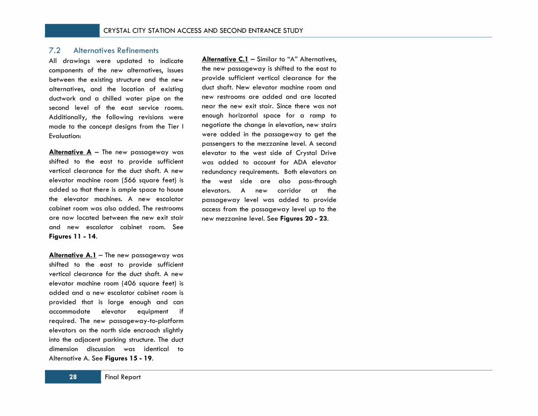
CRYSTAL CITY STATION ACCESS AND SECOND ENTRANCE STUDY
28 Final Report
7.2 Alternatives Refinements
All drawings were updated to indicate
components of the new alternatives, issues
between the existing structure and the new
alternatives, and the location of existing
ductwork and a chilled water pipe on the
second level of the east service rooms.
Additionally, the following revisions were
made to the concept designs from the Tier I
Evaluation:
Alternative A – The new passageway was
shifted to the east to provide sufficient
vertical clearance for the duct shaft. A new
elevator machine room (566 square feet) is
added so that there is ample space to house
the elevator machines. A new escalator
cabinet room was also added. The restrooms
are now located between the new exit stair
and new escalator cabinet room. See
Figures 11 - 14.
Alternative A.1 – The new passageway was
shifted to the east to provide sufficient
vertical clearance for the duct shaft. A new
elevator machine room (406 square feet) is
added and a new escalator cabinet room is
provided that is large enough and can
accommodate elevator equipment if
required. The new passageway-to-platform
elevators on the north side encroach slightly
into the adjacent parking structure. The duct
dimension discussion was identical to
Alternative A. See Figures 15 - 19.
Alternative C.1 – Similar to “A” Alternatives,
the new passageway is shifted to the east to
provide sufficient vertical clearance for the
duct shaft. New elevator machine room and
new restrooms are added and are located
near the new exit stair. Since there was not
enough horizontal space for a ramp to
negotiate the change in elevation, new stairs
were added in the passageway to get the
passengers to the mezzanine level. A second
elevator to the west side of Crystal Drive
was added to account for ADA elevator
redundancy requirements. Both elevators on
the west side are also pass-through
elevators. A new corridor at the
passageway level was added to provide
access from the passageway level up to the
new mezzanine level. See Figures 20 - 23.
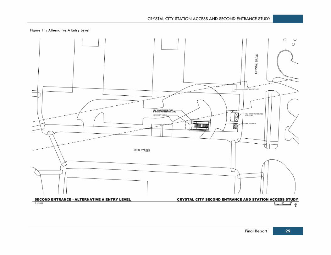
CRYSTAL CITY STATION ACCESS AND SECOND ENTRANCE STUDY
Final Report 29
Figure 11: Alternative A Entry Level
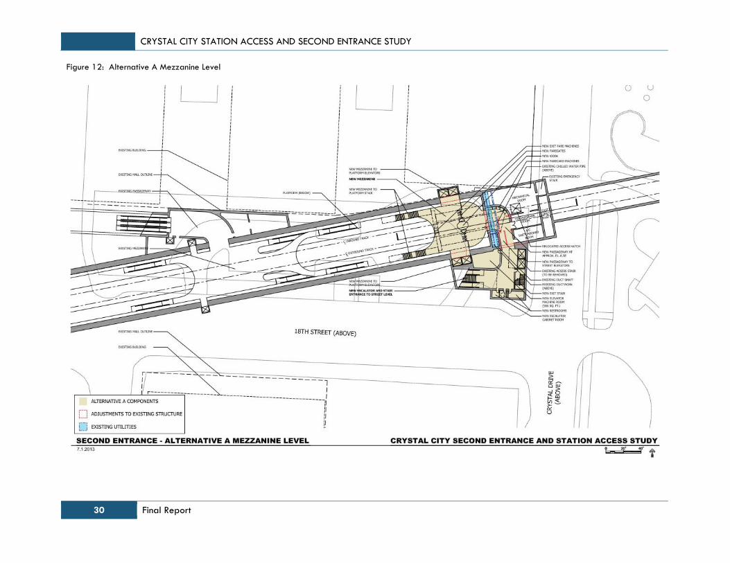
CRYSTAL CITY STATION ACCESS AND SECOND ENTRANCE STUDY
30 Final Report
Figure 12: Alternative A Mezzanine Level
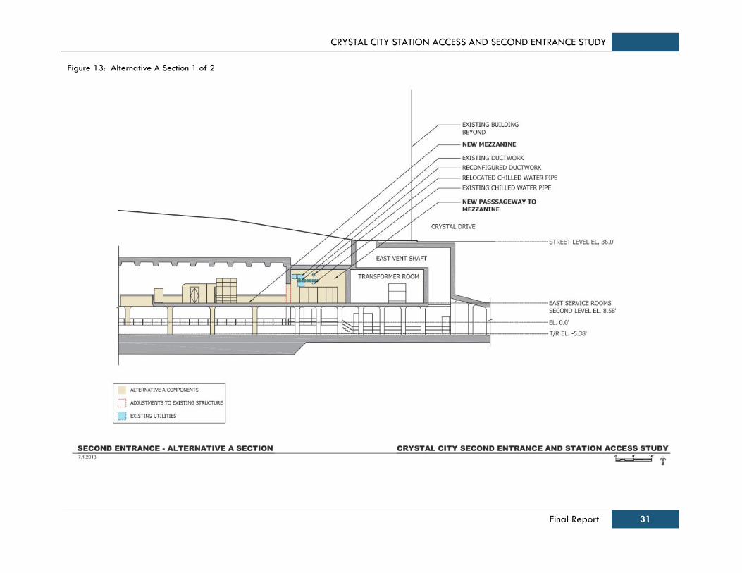
CRYSTAL CITY STATION ACCESS AND SECOND ENTRANCE STUDY
Final Report 31
Figure 13: Alternative A Section 1 of 2
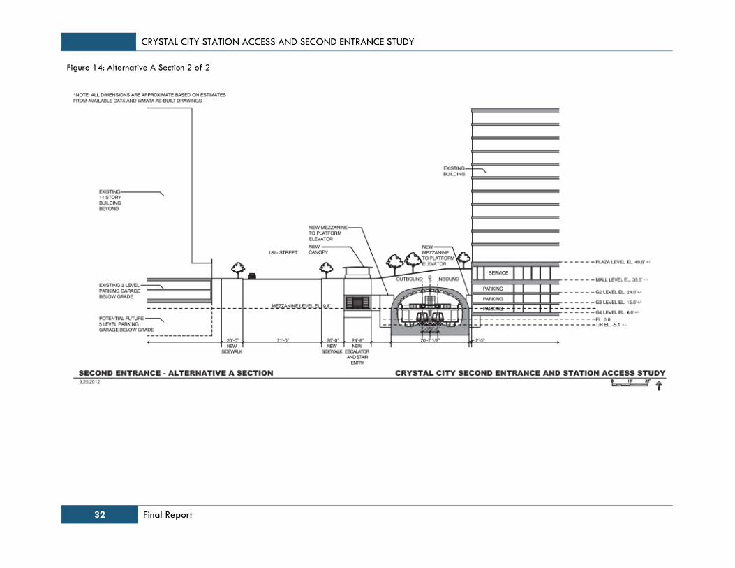
CRYSTAL CITY STATION ACCESS AND SECOND ENTRANCE STUDY
32 Final Report
Figure 14: Alternative A Section 2 of 2

CRYSTAL CITY STATION ACCESS AND SECOND ENTRANCE STUDY
Final Report 33
Figure 15: Alternative A.1 Entry Level
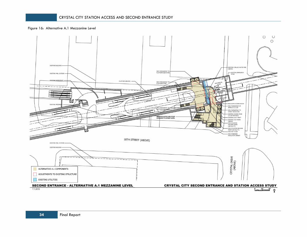
CRYSTAL CITY STATION ACCESS AND SECOND ENTRANCE STUDY
34 Final Report
Figure 16: Alternative A.1 Mezzanine Level
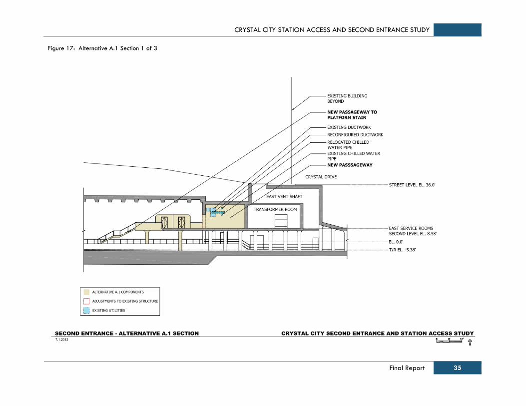
CRYSTAL CITY STATION ACCESS AND SECOND ENTRANCE STUDY
Final Report 35
Figure 17: Alternative A.1 Section 1 of 3
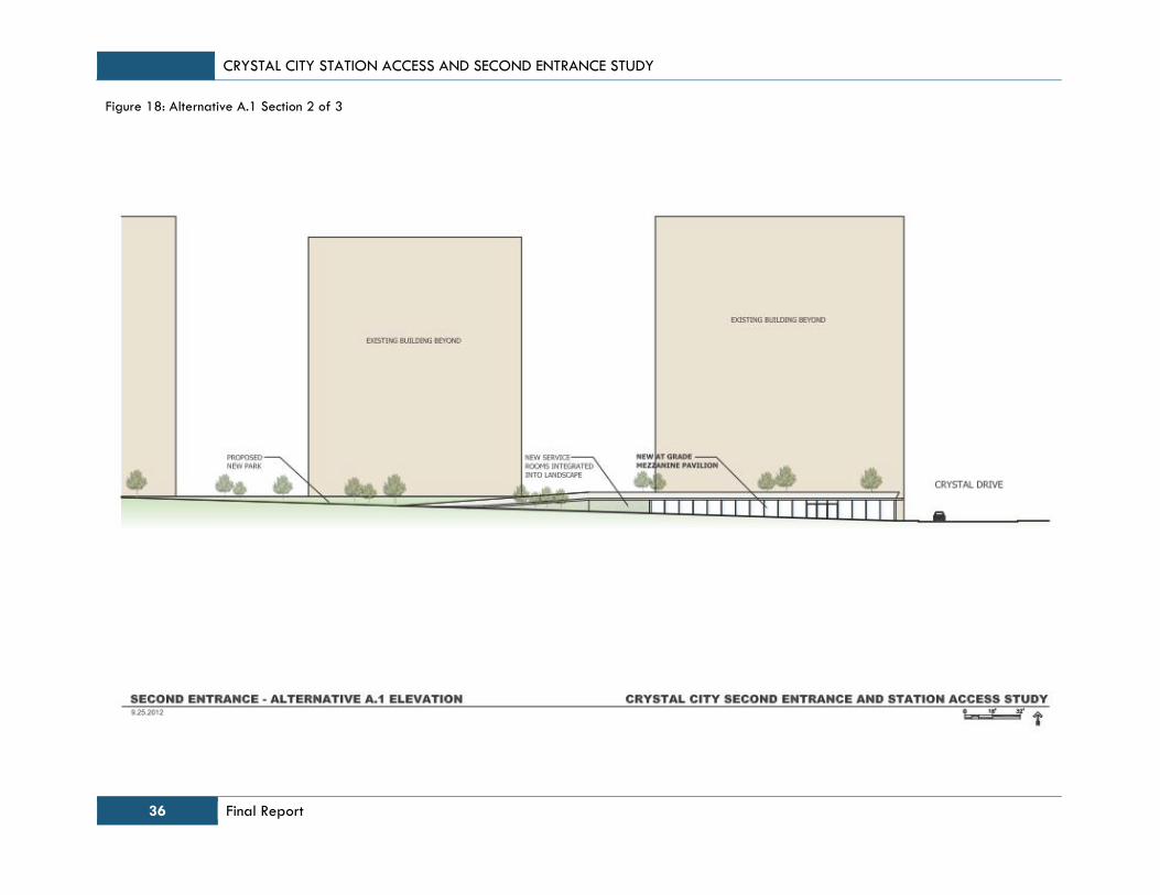
CRYSTAL CITY STATION ACCESS AND SECOND ENTRANCE STUDY
36 Final Report
Figure 18: Alternative A.1 Section 2 of 3

CRYSTAL CITY STATION ACCESS AND SECOND ENTRANCE STUDY
Final Report 37
Figure 19: Alternative A.1 Section 3 of 3

CRYSTAL CITY STATION ACCESS AND SECOND ENTRANCE STUDY
38 Final Report
Figure 20: Alternative C.1 Entry Level
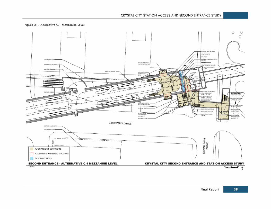
CRYSTAL CITY STATION ACCESS AND SECOND ENTRANCE STUDY
Final Report 39
Figure 21: Alternative C.1 Mezzanine Level
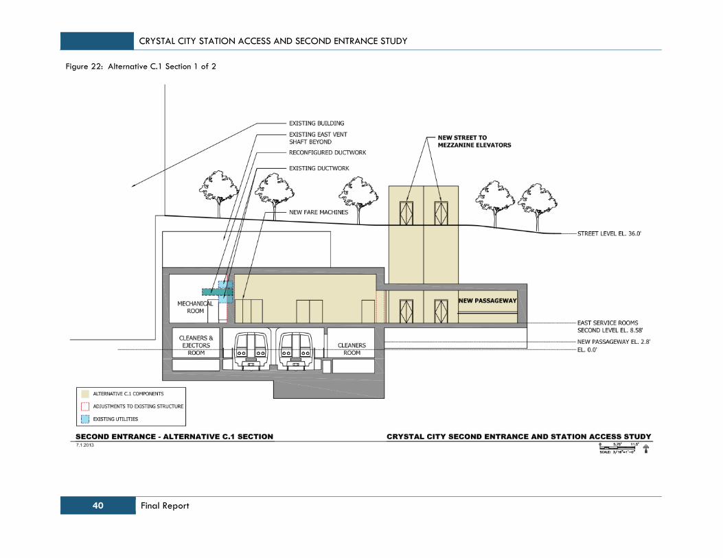
CRYSTAL CITY STATION ACCESS AND SECOND ENTRANCE STUDY
40 Final Report
Figure 22: Alternative C.1 Section 1 of 2
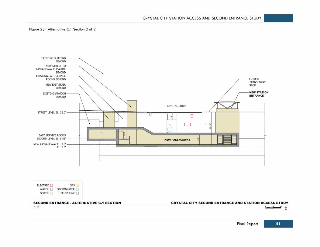
CRYSTAL CITY STATION ACCESS AND SECOND ENTRANCE STUDY
Final Report 41
Figure 23: Alternative C.1 Section 2 of 2
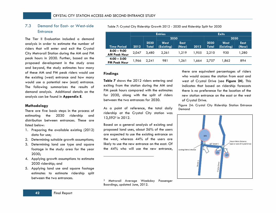
CRYSTAL CITY STATION ACCESS AND SECOND ENTRANCE STUDY
42 Final Report
Table 7: Crystal City Ridership Growth 2012 - 2030 and Ridership Split for 2030
Time Period
Entries Exits
2012 2030 Total
2030
2012 2030 Total
2030
West (Existing)
East (New)
West (Existing)
East (New)
8:00 – 9:00 AM Peak Hour
2,047 3,480 2,261 1,219 1,955 2,210 930 1,280
4:00 – 5:00 PM Peak Hour
1,966 2,241 981 1,261 1,664 2,757 1,862 894
Figure 24: Crystal City Ridership Station Entrance
Demand
7.3 Demand for East- or West-side
Entrance
The Tier II Evaluation included a demand
analysis in order to estimate the number of
riders that will enter and exit the Crystal
City Metrorail Station during the AM and PM
peak hours in 2030. Further, based on the
proposed development in the study area
and beyond, the study estimates how many
of these AM and PM peak riders would use
the existing (west) entrance and how many
would use a potential new (east) entrance.
The following summarizes the results of
demand analysis. Additional details on the
analysis can be found in Appendix E.
Methodology
There are five basic steps in the process of
estimating the 2030 ridership and
distribution between entrances. These are
listed below:
1. Preparing the available existing (2012)
data for use;
2. Determining suitable growth assumptions;
3. Determining land use type and square
footage in the study area for the year
2030;
4. Applying growth assumptions to estimate
2030 ridership; and
5. Applying land use and square footage
estimates to estimate ridership split
between the two entrances.
Findings
Table 7 shows the 2012 riders entering and
exiting from the station during the AM and
PM peak hours compared with the estimates
for 2030, along with the split of riders
between the two entrances for 2030.
As a point of reference, the total daily
ridership at the Crystal City station was
13,5922 in 2012.
Based on a general analysis of existing and
proposed land uses, about 56% of the users
are expected to use the existing entrance on
the west, whereas 44% of the users are
likely to use the new entrance on the east. Of
the 44% who will use the new entrance,
2 Metrorail Average Weekday Passenger Boardings, updated June, 2012.
there are equivalent percentages of riders
who would access the station from east and
west of Crystal Drive (see Figure 24). This
indicates that based on ridership forecasts
there is no preference for the location of the
new station entrance on the east or the west
of Crystal Drive.
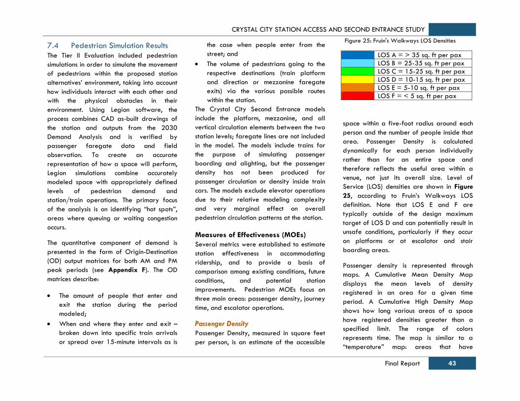
CRYSTAL CITY STATION ACCESS AND SECOND ENTRANCE STUDY
Final Report 43
Figure 25: Fruin's Walkways LOS Densities
LOS A = > 35 sq. ft per pax
LOS B = 25-35 sq. ft per pax
LOS C = 15-25 sq. ft per pax
LOS D = 10-15 sq. ft per pax
LOS E = 5-10 sq. ft per pax
LOS F = < 5 sq. ft per pax
7.4 Pedestrian Simulation Results
The Tier II Evaluation included pedestrian
simulations in order to simulate the movement
of pedestrians within the proposed station
alternatives’ environment, taking into account
how individuals interact with each other and
with the physical obstacles in their
environment. Using Legion software, the
process combines CAD as-built drawings of
the station and outputs from the 2030
Demand Analysis and is verified by
passenger faregate data and field
observation. To create an accurate
representation of how a space will perform,
Legion simulations combine accurately
modeled space with appropriately defined
levels of pedestrian demand and
station/train operations. The primary focus
of the analysis is on identifying “hot spots”,
areas where queuing or waiting congestion
occurs.
The quantitative component of demand is
presented in the form of Origin-Destination
(OD) output matrices for both AM and PM
peak periods (see Appendix F). The OD
matrices describe:
The amount of people that enter and
exit the station during the period
modeled;
When and where they enter and exit –
broken down into specific train arrivals
or spread over 15-minute intervals as is
the case when people enter from the
street; and
The volume of pedestrians going to the
respective destinations (train platform
and direction or mezzanine faregate
exits) via the various possible routes
within the station.
The Crystal City Second Entrance models
include the platform, mezzanine, and all
vertical circulation elements between the two
station levels; faregate lines are not included
in the model. The models include trains for
the purpose of simulating passenger
boarding and alighting, but the passenger
density has not been produced for
passenger circulation or density inside train
cars. The models exclude elevator operations
due to their relative modeling complexity
and very marginal effect on overall
pedestrian circulation patterns at the station.
Measures of Effectiveness (MOEs)
Several metrics were established to estimate
station effectiveness in accommodating
ridership, and to provide a basis of
comparison among existing conditions, future
conditions, and potential station
improvements. Pedestrian MOEs focus on
three main areas: passenger density, journey
time, and escalator operations.
Passenger Density
Passenger Density, measured in square feet
per person, is an estimate of the accessible
space within a five-foot radius around each
person and the number of people inside that
area. Passenger Density is calculated
dynamically for each person individually
rather than for an entire space and
therefore reflects the useful area within a
venue, not just its overall size. Level of
Service (LOS) densities are shown in Figure
25, according to Fruin’s Walkways LOS
definition. Note that LOS E and F are
typically outside of the design maximum
target of LOS D and can potentially result in
unsafe conditions, particularly if they occur
on platforms or at escalator and stair
boarding areas.
Passenger density is represented through
maps. A Cumulative Mean Density Map
displays the mean levels of density
registered in an area for a given time
period. A Cumulative High Density Map
shows how long various areas of a space
have registered densities greater than a
specified limit. The range of colors
represents time. The map is similar to a
“temperature” map: areas that have

CRYSTAL CITY STATION ACCESS AND SECOND ENTRANCE STUDY
44 Final Report
experienced high levels of density for a long
time appear red, those that have
experienced shorter periods of density
appear blue. This map is best used for
identifying “hot-spots” within a site: areas
where high levels of density are sustained.
For each model scenario, Cumulative Mean
Density Maps and Cumulative High Density
Maps are provided at key locations
throughout the station during the peak hour
and peak 15-minute period (see Figure 26
through Figure 31). The maps focus on the
platforms, mezzanines and circulation/
transfer areas, and provide results that can
be readily used to compare performance
across scenarios. The key quantitative MOE
relating to Passenger Density is the
percentage of passengers experiencing LOS
E and F during the peak hour and peak 15-
minute period.
Journey Time
Journey Time (JT) is the time taken by a
person to complete his or her course through
a model. JT is measured two ways; upon
alighting a train and ending at the street
level, and upon entering at street level and
arriving at the destination platform, thus
excluding platform waiting. By excluding
platform waiting, the times truly represent
the circulation routes within the station, rather
than being skewed by train headway
variability or platform congestion.
Escalator Operations
A zone is established adjacent to each
escalator where “boarding” takes place.
This zone measures the occupancy time for
passengers traveling via each escalator.
Times are presented in terms of how long a
person in the queue takes to clear for each
escalator exhibiting queuing during the
station’s AM and PM peak hour. MOEs for
escalators are: 1) Time in Queue for each
passenger - average, maximum and 95th
percentile; and 2) Cumulative Time a queue
exists at an escalator boarding area.
Findings
The differences in the pedestrian simulation
MOEs between the three second entrance
alternatives are fairly insignificant. All three
alternatives provide significant improvement
over the 2030 No Build with similar benefits.
Detailed Pedestrian Simulation MOE findings
can be seen in Appendix F.
Alternative A.1 provides the best
performance of the three alternatives in
terms of pedestrian density, particularly in
the New Mezzanine area, as pedestrians are
more distributed through the passageway
and entrance pavilion before queuing occurs
at the faregates. In Alternative A.1,
faregates are located on the surface level,
which allows for the furthest distance from
the platform area for pedestrian queuing to
occur. See Table 8 for the combined
average percentages of LOS E and F of all
scenarios.
Alternatives A.1 and C.1 have longer
average journey times than Alternative A
due to the longer passageways upon
entering/exiting at the street level.
Alternative A provides the most direct route
between the platform and street level.
All three alternatives provide the same level
of benefits in terms of internal escalator
operations.
Table 8: Combined Average Percent LOS E & F
Scenario Combined Average % LOS E & LOS F
2012 Existing 7%
2030 No Build 18%
2030 Alternative A 6%
2030 Alternative A.1 5%
2030 Alternative C.1 6%
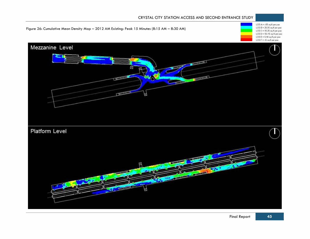
CRYSTAL CITY STATION ACCESS AND SECOND ENTRANCE STUDY
Final Report 45
Figure 26: Cumulative Mean Density Map – 2012 AM Existing: Peak 15 Minutes (8:15 AM – 8:30 AM)
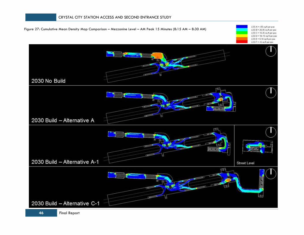
CRYSTAL CITY STATION ACCESS AND SECOND ENTRANCE STUDY
46 Final Report
Figure 27: Cumulative Mean Density Map Comparison – Mezzanine Level – AM Peak 15 Minutes (8:15 AM – 8:30 AM)
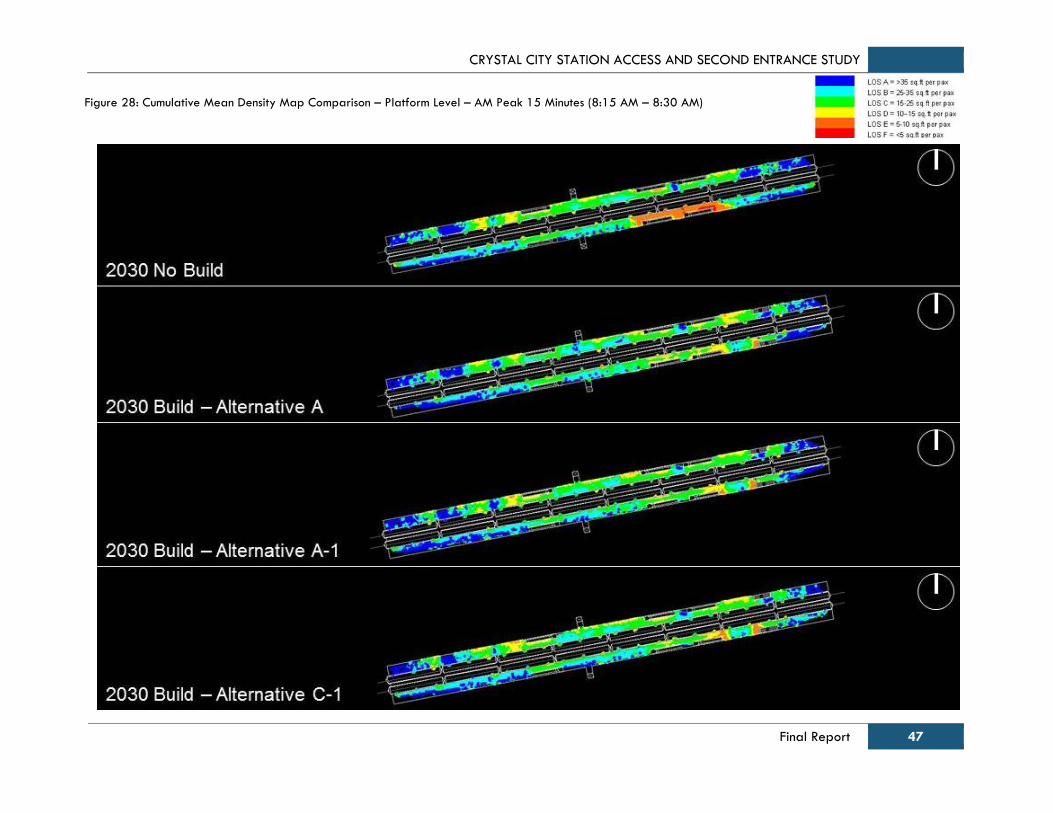
CRYSTAL CITY STATION ACCESS AND SECOND ENTRANCE STUDY
Final Report 47
Figure 28: Cumulative Mean Density Map Comparison – Platform Level – AM Peak 15 Minutes (8:15 AM – 8:30 AM)

CRYSTAL CITY STATION ACCESS AND SECOND ENTRANCE STUDY
48 Final Report
Figure 29: Cumulative Mean Density Map – 2012 PM Existing: Peak 15 Minutes (5:15 PM – 5:30 PM)
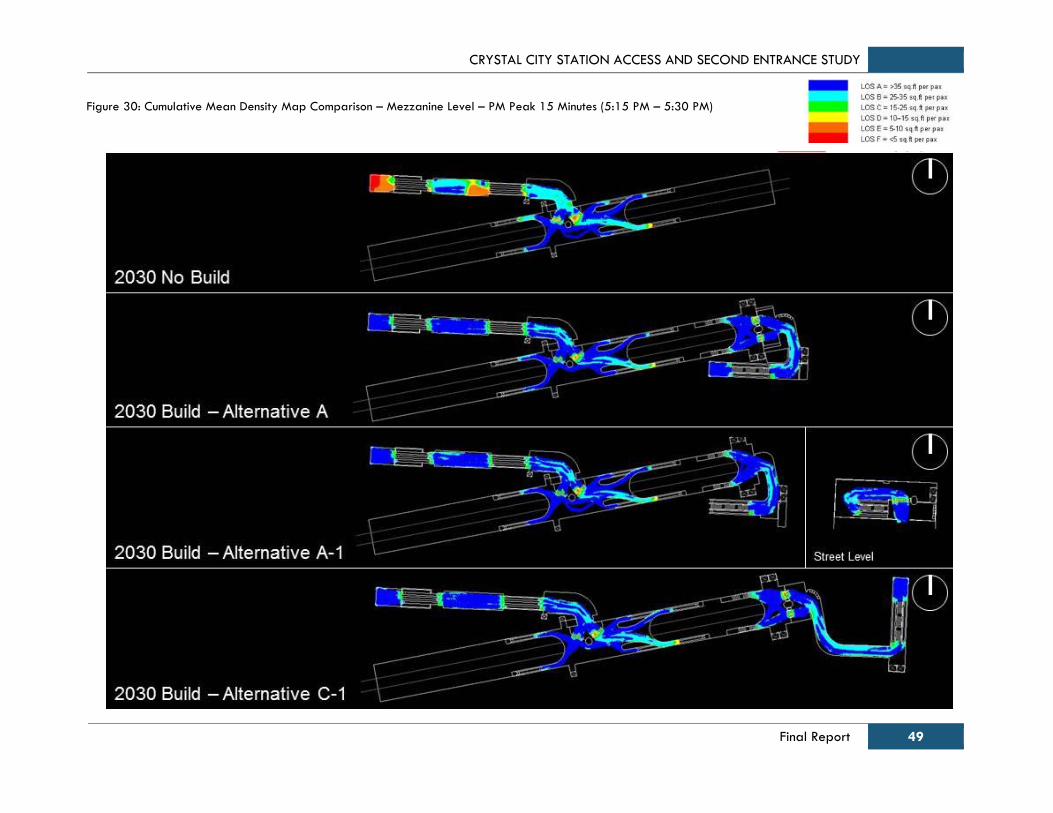
CRYSTAL CITY STATION ACCESS AND SECOND ENTRANCE STUDY
Final Report 49
Figure 30: Cumulative Mean Density Map Comparison – Mezzanine Level – PM Peak 15 Minutes (5:15 PM – 5:30 PM)
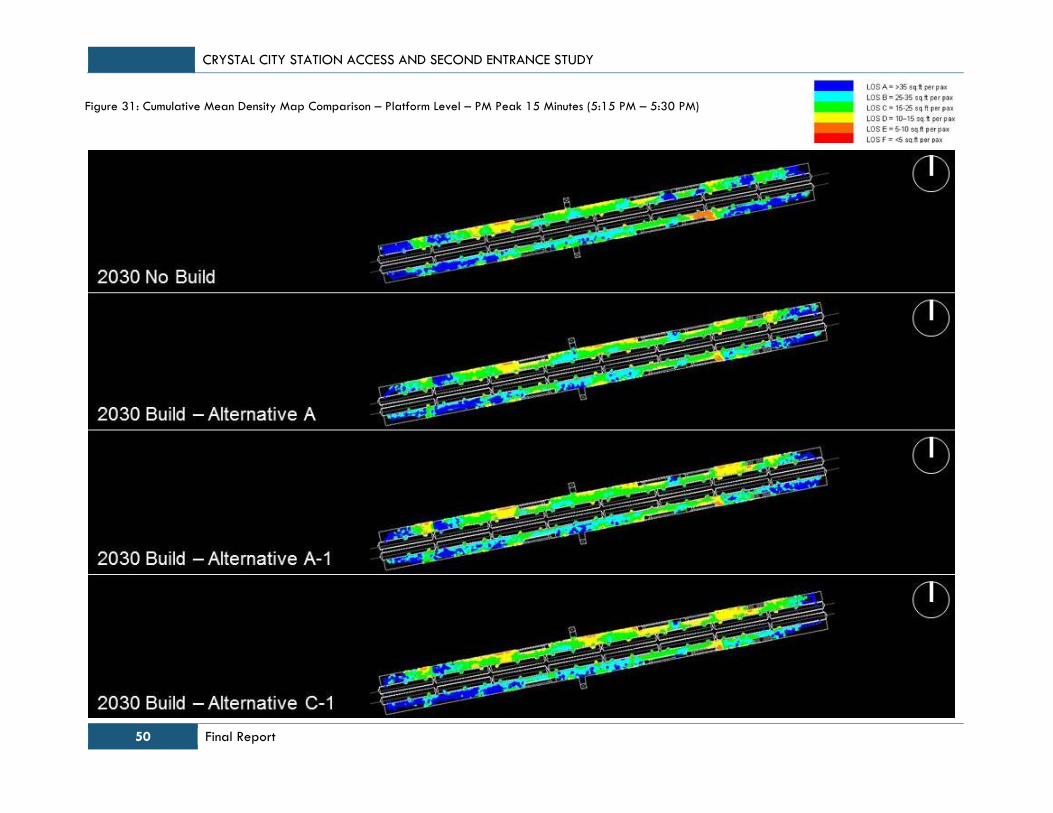
CRYSTAL CITY STATION ACCESS AND SECOND ENTRANCE STUDY
50 Final Report
Figure 31: Cumulative Mean Density Map Comparison – Platform Level – PM Peak 15 Minutes (5:15 PM – 5:30 PM)
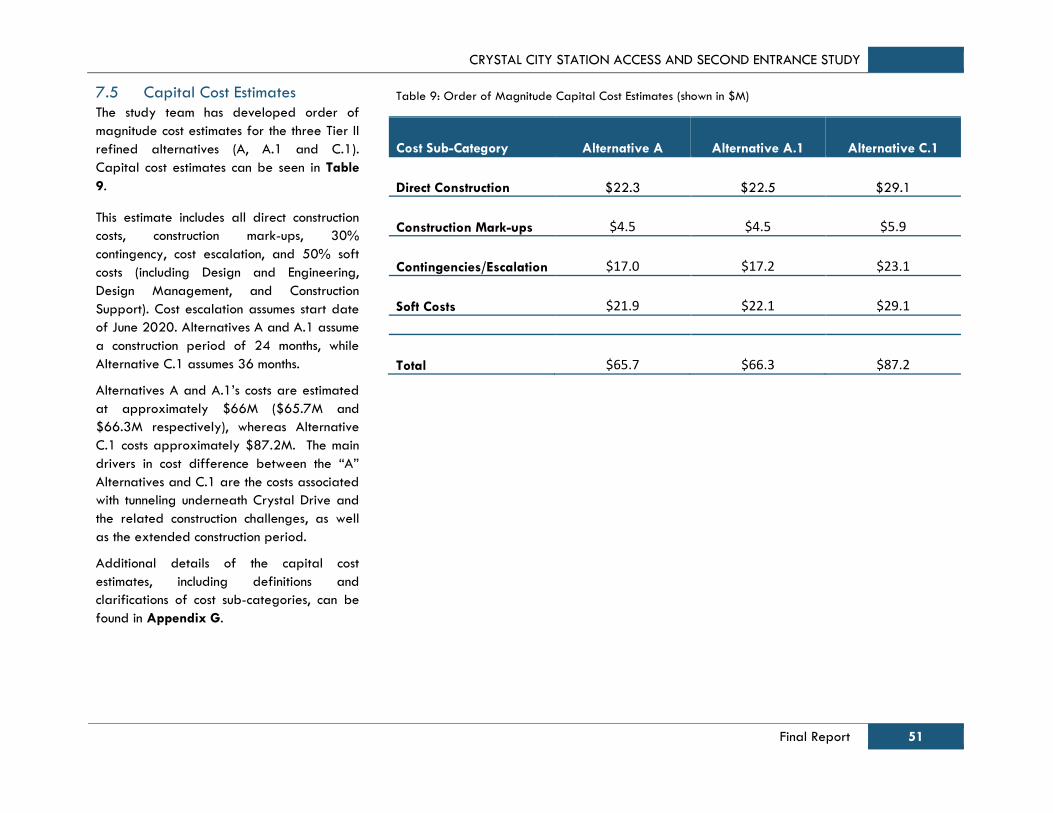
CRYSTAL CITY STATION ACCESS AND SECOND ENTRANCE STUDY
Final Report 51
7.5 Capital Cost Estimates
The study team has developed order of
magnitude cost estimates for the three Tier II
refined alternatives (A, A.1 and C.1).
Capital cost estimates can be seen in Table
9.
This estimate includes all direct construction
costs, construction mark-ups, 30%
contingency, cost escalation, and 50% soft
costs (including Design and Engineering,
Design Management, and Construction
Support). Cost escalation assumes start date
of June 2020. Alternatives A and A.1 assume
a construction period of 24 months, while
Alternative C.1 assumes 36 months.
Alternatives A and A.1’s costs are estimated
at approximately $66M ($65.7M and
$66.3M respectively), whereas Alternative
C.1 costs approximately $87.2M. The main
drivers in cost difference between the “A”
Alternatives and C.1 are the costs associated
with tunneling underneath Crystal Drive and
the related construction challenges, as well
as the extended construction period.
Additional details of the capital cost
estimates, including definitions and
clarifications of cost sub-categories, can be
found in Appendix G.
Table 9: Order of Magnitude Capital Cost Estimates (shown in $M)
Cost Sub-Category Alternative A Alternative A.1 Alternative C.1
Direct Construction $22.3 $22.5 $29.1
Construction Mark-ups $4.5
$4.5 $5.9
Contingencies/Escalation $17.0 $17.2 $23.1
Soft Costs $21.9 $22.1 $29.1
Total $65.7 $66.3 $87.2
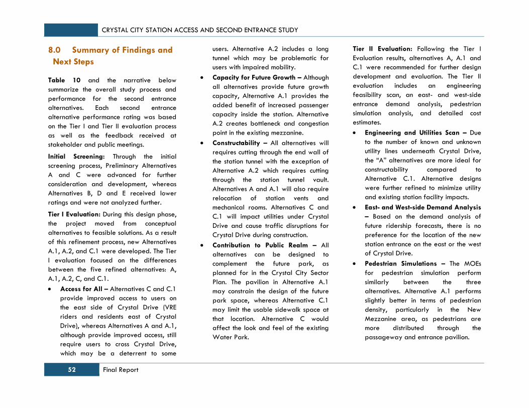
CRYSTAL CITY STATION ACCESS AND SECOND ENTRANCE STUDY
52 Final Report
8.0 Summary of Findings and
Next Steps
Table 10 and the narrative below
summarize the overall study process and
performance for the second entrance
alternatives. Each second entrance
alternative performance rating was based
on the Tier I and Tier II evaluation process
as well as the feedback received at
stakeholder and public meetings.
Initial Screening: Through the initial
screening process, Preliminary Alternatives
A and C were advanced for further
consideration and development, whereas
Alternatives B, D and E received lower
ratings and were not analyzed further.
Tier I Evaluation: During this design phase,
the project moved from conceptual
alternatives to feasible solutions. As a result
of this refinement process, new Alternatives
A.1, A.2, and C.1 were developed. The Tier
I evaluation focused on the differences
between the five refined alternatives: A,
A.1, A.2, C, and C.1.
Access for All – Alternatives C and C.1
provide improved access to users on
the east side of Crystal Drive (VRE
riders and residents east of Crystal
Drive), whereas Alternatives A and A.1,
although provide improved access, still
require users to cross Crystal Drive,
which may be a deterrent to some
users. Alternative A.2 includes a long
tunnel which may be problematic for
users with impaired mobility.
Capacity for Future Growth – Although
all alternatives provide future growth
capacity, Alternative A.1 provides the
added benefit of increased passenger
capacity inside the station. Alternative
A.2 creates bottleneck and congestion
point in the existing mezzanine.
Constructability – All alternatives will
requires cutting through the end wall of
the station tunnel with the exception of
Alternative A.2 which requires cutting
through the station tunnel vault.
Alternatives A and A.1 will also require
relocation of station vents and
mechanical rooms. Alternatives C and
C.1 will impact utilities under Crystal
Drive and cause traffic disruptions for
Crystal Drive during construction.
Contribution to Public Realm – All
alternatives can be designed to
complement the future park, as
planned for in the Crystal City Sector
Plan. The pavilion in Alternative A.1
may constrain the design of the future
park space, whereas Alternative C.1
may limit the usable sidewalk space at
that location. Alternative C would
affect the look and feel of the existing
Water Park.
Tier II Evaluation: Following the Tier I
Evaluation results, alternatives A, A.1 and
C.1 were recommended for further design
development and evaluation. The Tier II
evaluation includes an engineering
feasibility scan, an east- and west-side
entrance demand analysis, pedestrian
simulation analysis, and detailed cost
estimates.
Engineering and Utilities Scan – Due
to the number of known and unknown
utility lines underneath Crystal Drive,
the “A” alternatives are more ideal for
constructability compared to
Alternative C.1. Alternative designs
were further refined to minimize utility
and existing station facility impacts.
East- and West-side Demand Analysis
– Based on the demand analysis of
future ridership forecasts, there is no
preference for the location of the new
station entrance on the east or the west
of Crystal Drive.
Pedestrian Simulations – The MOEs
for pedestrian simulation perform
similarly between the three
alternatives. Alternative A.1 performs
slightly better in terms of pedestrian
density, particularly in the New
Mezzanine area, as pedestrians are
more distributed through the
passageway and entrance pavilion.

CRYSTAL CITY STATION ACCESS AND SECOND ENTRANCE STUDY
Final Report 53
Capital Cost Estimates – Alternatives A
and A.1’s costs are estimated at
approximately $66M ($65.7M and
$66.3M respectively), whereas
Alternative C.1 costs approximately
$87.2M. The main drivers in cost
difference between the “A”
Alternatives and C.1 are the costs
associated with tunneling underneath
Crystal Drive and the related
construction challenges, as well as the
extended construction period.
Recommendation and Next Steps
Based on the performance ratings for each
evaluation criteria, this study concludes that
all three alternatives perform similarly and
are the appropriate and feasible design
alternatives for a second entrance to the
Crystal City Metrorail Station. The two “A”
Alternatives provide different designs
choices of the entrance at the surface level,
either a typical Metrorail entrance canopy
or a larger entrance pavilion. It would be
beneficial as a next step to gather public
and stakeholder opinions for an entrance
pavilion and other impacts or benefits to
the park design at this location. Alternative
C.1 provides the best multimodal
connections with its proximity to the
northbound transitway stop and allowing
for the most direct connection for VRE
passengers transferring to the Metrorail
system. Additional engineering and design
work may be needed in order to determine
the cost effectiveness of this alternative.
After a period of public comment and a
decision from WMATA and County officials,
the recommended alternative will be
carried into the next phase of work,
including required environmental analysis
and detailed engineering design. Project
funding sources will be more explicitly
defined and programmed. Throughout the
process, there will be ongoing coordination
with key stakeholders, including owners of
adjacent property, utility companies, and
County officials.

CRYSTAL CITY STATION ACCESS AND SECOND ENTRANCE STUDY
54 Final Report
Table 10: Second Entrance Alternatives Evaluation Summary Matrix
CRYSTAL CITY STATION ACCESS AND SECOND ENTRANCE STUDY
Final Report 55
This page left intentionally blank.
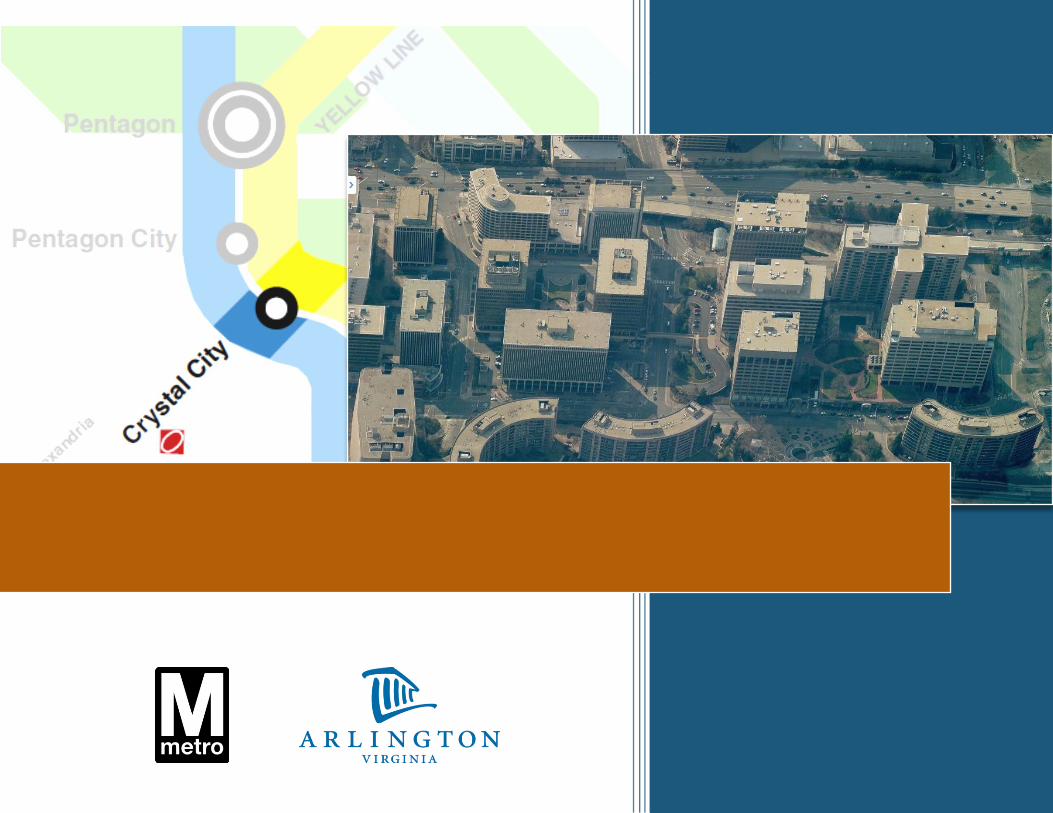
CRYSTAL CITY STATION ACCESS AND SECOND ENTRANCE STUDY