Embed Size (px)
Citation preview
BRUKER
CryoProbe System
Site Planning GuideVersion 2

The information in this manual may be altered without notice.
BRUKER accepts no responsibility for actions taken as a resultof use of this manual. BRUKER accepts no liability for any mis-takes contained in the manual, leading to coincidental damage,whether during installation or operation of the instrument. Un-authorized reproduction of manual contents, without writtenpermission from the publishers, or translation into another lan-guage, either in full or in part, is forbidden.
This manual was written by
M. Schick, D. Marek, R. Triebe, D. Oberli
© March 7, 2001: Bruker AG
Fällanden, Switzerland
P/N: Z31524DWG-Nr: 1231020

CryoProbe Site Planning BRUKER 3 (63)
Contents
Contents ............................................................... 3
1 Introduction .......................................................... 51.1 How to use this manual ....................................................... 51.2 CryoProbe System overview ................................................ 51.3 61.4 Conventions ........................................................................ 6
2 Site planning ......................................................... 92.1 Example .............................................................................. 92.2 Compatibility ....................................................................... 92.3 How to plan the positions of the units ................................. 13
Access to the magnet ....................................................14Stray field considerations ...............................................14He Transferline ..............................................................15Remote location of the He Compressor ..........................15Acoustic isolation ...........................................................16Dimensions and weights ................................................16Site planning sequence ..................................................17
2.4 Supplies ............................................................................ 18Electricity .......................................................................18Air conditioning ..............................................................19Cooling water ................................................................20VT gas ...........................................................................21Pneumatic gas ...............................................................21Helium gas ....................................................................21
2.5 Site Planning Questionnaire .............................................. 22
3 System description ............................................. 233.1 CryoProbe ......................................................................... 233.2 CryoPlatform ..................................................................... 24
Mounting Hardware ........................................................24CryoCooling Unit ...........................................................24He Compressor ..............................................................26
3.3 Cryo-compatible preamplifier assembly ‘HPPR CRP’ ......... 273.4 Software ............................................................................ 27
4 Bruker contact .................................................... 294.1 CryoProbe information ....................................................... 294.2 CryoProbe service ............................................................. 29
A Related documents ............................................. 31
4 (63) BRUKER CryoProbe Site Planning
Contents
B Building blocks for site planning ........................ 33B.1 AVANCE spectrometer ......................................................... 33B.2 CryoProbe System ............................................................ 34B.3 CryoProbe in magnet ........................................................ 35B.4 Stray fields of other magnets ............................................. 36
C Conversion of metric units .................................. 41
D Frequently asked questions ................................ 43D.1 System configuration ......................................................... 43D.2 NMR operation .................................................................. 44D.3 Basic aspects .................................................................... 45
E Glossary ............................................................... 47
Figures ................................................................. 53
Tables .................................................................. 55
Index .................................................................... 57

CryoProbe Site Planning BRUKER 5 (63)
Introduction 1
1000000
BRUKER CryoProbes™ offer a dramatic increase in signal-to-noise ratio (S/N) byreducing the operating temperature of the NMR coil assembly and the preamplifi-er. Their spectroscopic handling is very similar to a conventional probe. While thesample temperature is stabilized at a user-defined value around room tempera-ture, the NMR coil assembly - located a few millimeters from the sample - iscooled with cryogenic helium gas. An automatic closed-cycle cooling system con-trols all functions and guarantees excellent stability during short and long-term ex-periments. As a result, the system is easy to handle. CryoProbes open new fieldsfor NMR applications e.g. where low sample concentration or long measurementtime are critical.
How to use this manual 1.1
0
This CryoProbe System Site Planning Guide will help you to find out if an NMRlaboratory qualifies as a site for a CryoProbe System, which preparations are nec-essary for a smooth installation and operation, and which options should be con-sidered before placing an order.
If you have a specific question, use
- “Contents”,- “Index” or - “Frequently asked questions”
to locate the answer.
Further information can be found in the manuals listed in "Related documents"on page 31.
CryoProbe System overview 1.2
0
A CryoProbe System consists of several subunits: CryoProbe, CryoPlatform,cryo-compatible HPPR CRP, and He steel-cylinder (Figure 1.1.).
The term ‘CryoPlatform’ summarizes the parts required to operate a CryoProbesuch as the CryoCooling Unit, the He Compressor, the Mounting Hardware at themagnet etc. It is compatible with all BRUKER CryoProbes and only one per spec-trometer is needed.

6 (63) BRUKER CryoProbe Site Planning
Introduction
1.3
Conventions 1.4
0 SMALL CAPS ITALIC setting of a hardware switch or button
Courier small contents of a file
Figure 1.1. The CryoProbe™ System
AVANCE Console
MagnetCryoProbeTM
He-Compressor
HPPR CRPor
HPPR/2
BR
UK
ER
CryoPlatformTM
Room temperature He Gaspressure lines & Cables
Transferline(Part of
CryoCoolingUnit)
BRU
KER
TransferlineSupport
He Gascylinder(to beprovidedbycustomer)
Connenction to He-Gascylinder incl. Pressurereduction valve
CryoCoolingUnitWith 2m Transferline
CryoProbeMountingHardware
CoolingWaterSupply(to beprovidedbycustomer)

Conventions
CryoProbe Site Planning BRUKER 7 (63)
Courier small italic system response
Courier file or directory name
Courier bold Unix™ or Windows™ NT keyboard command
Courier italic bold BRUKER NMR Suite keyboard command
Times bold Unix or Windows NT object clicked with the mouse
Times italic bold BRUKER NMR Suite object clicked with the mouse
Times italic host name, User name etc.
< > place holder

8 (63) BRUKER CryoProbe Site Planning
Introduction

CryoProbe Site Planning BRUKER 9 (63)
Site planning 22000000
The "Site planning example" on page 10 shows what an NMR laboratory with aCryoProbe System could look like. "Compatibility" on page 9 will tell you if yourspectrometer qualifies for a CryoProbe System. The major considerations and re-strictions for the site planning are outlined in "How to plan the positions of theunits" on page 13. Since the positions of the units are interdependent, there is apreferred "Site planning sequence" on page 17. For convenience, all neces-sary "Supplies" on page 18 are listed and a few hints for the "Site PlanningQuestionnaire" on page 22 are given.
The individual units are explained in more detail in "System description" onpage 23.
Example 2.1
0 An example for a CryoProbe System siting is shown in Figure 2.1..
Compatibility 2.2
0
Spectrometers
The CryoProbe System can be connected to BRUKER AVANCE NMR spectrome-ters only. It is not compatible with the hardware of other spectrometer architec-tures such as BRUKER AMX/ARX, AC, AM, MSL, etc. or other brands.
Magnets
The CryoProbes available fit any standard-bore magnet system.
The magnet and CryoCooling Unit should be standing on the same floor level. Ifthis is not the case, e.g. the magnet is in a small pit, BRUKER specialists need tocheck if the siting of a CryoProbe System is possible at all.
Free access is required to the magnet bottom for the insertion of the CryoProbe,see Figure 2.3.. The CryoProbe will be fixed to the magnet by special MountingHardware which is attached to the lower RT flange of the magnet bore (see Fig-ure 2.2.). Make sure that it will not interfere with the operation of any drop-off plateor vacuum valve.
Certain BRUKER/SPECTROSPIN 500 MHz and 600 MHz magnets (i.e. Dewar typesD220, D221, D260 and D262) need a minor modification of their horizontallycross-linked magnet stand: two pillar braces in front must be exchanged for spe-cial cranked braces.
Wide-bore systems fitted with a standard-bore shim system currently cannot beused with a CryoProbe because their shim tube is longer.

10 (63) BRUKER CryoProbe Site Planning
Site planning
Shim systems
BOSS-2 shim systems should be used for optimum performance. If the shim sys-tem is equipped with a red spinner stator, it must be exchanged for a shim systemwith a blue one. The color of the stator can be seen easily from below the magnetusing a light when no probe is in the bore.
Shim systems of other types or brands are not compatible.
If an optional ring for cooling/heating the shim system with compressed air ismounted at the magnet bore bottom, it can be left in place.
The default orientation of a CryoProbe is such that its front is parallel to themagnet front for a BRUKER/SPECTROSPIN magnet. However, all orientations arepossible in which no geometrical conflict occurs between shim system bottomplate, Mounting Hardware, and CryoProbe (see Figure 2.2.). In certain cases itmight become necessary to rotate the shim system. Notify BRUKER if the cable ofthe shim system does not point to the rear of the magnet with a precision of about
Cryo
CoolingU
nit
Figure 2.1. Site planning example
refillDewar
two-
bay
cabi
net
BCU05
gas
tabl
em
onito
rO
2
1 m
HPPR
windows (no direct sunlight)
space forservice
He
com
pr.
wat
er-c
.
water chilleroutdoor part
wat
erch
iller
indo
orpa
rt
air flow
7.5 kW
3.6 kW
0.5 kW
3 phases
1 phase
3 phases
~ 3 kW1 phase
water chiller
gas
1.10 m
1.30 m
0.4 kW1 phase
2.7 m
0.4 kW1 phase
<10
m
< 7 m
2 m
6m
(20
m)
500
(UPS)
(UPS)
(UPS)
Only major cables and connections are indicated.A UPS is recommended for certain units.
Helium gas for LHerefill of magnet
scale 1:50

Compatibility
CryoProbe Site Planning BRUKER 11 (63)
Figure 2.2. Interface plate of Mounting Hardware to magnet
r = 25.1 mm
R = 38 mm
140 mm
∅ = 6 mm
224
mm
10 mm
magnet bore
holes for fixturescrews to magnet
front
CryoProbe body
BOSS-2 shim systembottom plate
corner of the shim systembottom plate that restricts the possible orientations
of the Mounting Hardware
CryoProbe guiding rod
scale 1:1

12 (63) BRUKER CryoProbe Site Planning
Site planning
± 10°. 500 MHz magnets with a horizontally cross-linked stand and cranked pillarbraces (Dewar types D220 and D221) permit only one orientation: the CryoProbefront must be parallel with the magnet front because it must fit into the crankedpillar braces.
Amplifiers
Standard BLAXH50 and BLAX300 amplifiers are well-suited for CryoProbes. ACryoProbe requires much less RF power than a conventional probe. Be carefulwith the higher output power of BLAH100, BLAX500, BLAX1000, etc.
Sample changer and automation
B-ACS 60/120 sample changers can be used with a CryoProbe provided theirmain vertical column ends at the height of the magnet dewar bottom and does notextend down to the floor. An existing long column B-ACS can be upgraded to ashort column. The column will be attached directly to the magnet with a B-ACSholder (see Table 2.1.). However, this is a major modification of the samplechanger. In any case, a B-ACS must be attached to the magnet front because themagnet’s helium ports and tubes do not permit access from another side.
NMR SIXPACK™ or NMR CASE™ sample changers are compatible without anyspecial considerations because they sit on the magnet top.
A QNP pneumatic unit is spatially incompatible with a CryoProbe setup and has tobe removed during CryoProbe operation.
Table 2.1. Compatible B-ACS 60/120 holders
magnet system magnet stand B-ACS holder
500 MHz, D120/51 (Z280120) Z58514 (= Z26247 V2) Z57334
500 MHz, D122/52 (Z280121, O019) Z58514 (= Z26247 V2) Z57334
500 MHz, D220/52 (Z29715) any Z51923
500 MHz UltraShield, D220/52 (Z29715) any Z51923
500 MHz UltraShield, D221/54 (Z54933) any Z51923
500 MHz UltraShield, D350/54 (Z56523) any Z57083
500 MHz UltraShield, D360/54 (Z56524) any Z57084
500 MHz Oxford 500/52, type IV, round bottom (29511, O049)
Z28518 (= Z26247 V6) Z57810
600 MHz UltraShield, D26x/52 (Z29704) any Z51922
600 MHz UltraShield, D262/54 (Z54238) any Z51922
600 MHz UltraShield, D360/54 (Z56525) any Z57084
600 MHz Oxford 600/51, round bottom (29512, O109)
Z28516 (= Z26247 V4) Z57811
How to plan the positions of the units
CryoProbe Site Planning BRUKER 13 (63)
VT unit
The VT unit must feature a Pt100 sensor port. Recommended units are B-VT2000or B-VT3000. The B-VT3200 and B-VT3300 may lead to inferior results due to themore coarse steps used in their temperature regulation loop. The B-VT3300 is notable to perform a self-calibration with a CryoProbe.
The BCU05 gas cooler and a CryoProbe System can be installed side by side.See the specific CryoProbe data sheets for the allowed sample temperature rang-es.
Preamplifier HPPR
An existing HPPR must be exchanged for a cryo-compatible HPPR CRP becausethe CryoProbes feature separate lines for transmit and receive. The HPPR CRPconfiguration depends on the nuclear frequencies of all CryoProbes and conven-tional probes which are to be used with the spectrometer. All kinds of HPPR mod-ules can be incorporated into an HPPR CRP assembly at any time.
RF filters
All RF filters needed for the CryoProbe are built-in already or supplied with theHPPR CRP.
Receivers
A high quality receiver system is mandatory to maintain the high signal-to-noiseratio provided by the CryoProbe. The effective digitizer resolution should be 18 bitor more to keep quantization noise at a negligible level.
For small receiver gain values, i.e. rg < ~256, the signal-to-noise tends to de-crease in proportion to rg. This situation typically occurs for samples containingH2O or other concentrated substances. Then, an RX22 receiver of ECL07 or lateris beneficial which can be hardware configured to introduce less noise at low rgat the expense of a reduced overall gain.
Accessories
A Radiation Damping Control Unit (RDCU) cannot be used with a CryoProbe be-cause the current versions of the two systems are incompatible.
Software
XWIN-NMR 2.0 or later with software enhancements, XWIN-NMR 2.6 or later arefully compatible.
How to plan the positions of the units 2.3
0 To a certain extent the positions of the components are mutually dependent. Also,the location of the "Supplies" on page 18 should be taken into account beforesending a definite site plan to BRUKER. A drawing of your laboratory to scale 1:50with a transparent copy of the "Building blocks for site planning" on page 33will help.
CAUTION: All components of a CryoProbe System (including He Compressor)are designed and specified strictly for indoor use.

14 (63) BRUKER CryoProbe Site Planning
Site planning
Access to the magnet 2.3.1
A spatial channel of e.g. at least 578 × 195 mm [height × width] is needed to inserta 500 MHz CryoProbe (see Figure 2.3. and Table 2.2.). For insertion and remov-al of the heavy CryoProbe, there must be enough space to give two people simul-taneous access to the magnet bottom. The clearing between shim system bottomplate and floor must be at least 578 mm (at 500 MHz) when the magnet anti-vibra-tion air suspension is ‘off’.
IMPORTANT: A magnet refill with cryogenic liquids must be possible at all times.
NOTE: A QNP pneumatic unit is spatially incompatible with a CryoProbe setupand has to be removed during CryoProbe operation.
The magnet and CryoCooling Unit should be standing on the same floor level. Ifthis is not the case, e.g. the magnet is in a small pit, BRUKER specialists need tocheck if the siting of a CryoProbe System is possible at all.
Stray field considerations 2.3.2
The He Compressor, and He steel-cylinder have to be kept outside the 0.5 mTfield. As a rule, all spectrometer and CryoProbe System components should be as
H1
W1
Free channel forInsertion ofCryoProbe
Front ViewSide View
Shim System
CryoProbe
Figure 2.3. Required access to the magnet bottom
Table 2.2. Access space
ν[MHz]
H1[mm]
W1[mm]
500 578 195
600 628 195

How to plan the positions of the units
CryoProbe Site Planning BRUKER 15 (63)
far away from the magnets as possible. In particular, the He steel-cylinder and itsentire transport path must always be outside the 0.5 mT range. The CryoCoolingUnit should be kept outside the 5 mT range.
See also the stray field considerations in ‘AVANCE 200-700: Introduction to SitePlanning’ (on BASH CD).
He Transferline 2.3.3
The He Transferline between the CryoCooling Unit and the CryoProbe must bebent to allow the insertion of the CryoProbe and to reduce spectral artefacts dueto mechanical vibrations.
length: 2 m (up to 4m on request)bending radius: ≥ 0.7 mbending angle: 100° - 140°
The recommended bending range of the He Transferline is indicated in Figure2.4. by its four extreme positions.
Remote location of the He Compressor 2.3.4
The use of extended Flexlines (20 m option instead of standard 6 m) between theCryoCooling Unit and He Compressor allows installation of the He Compressor ina remote room. Compared to a position close to the spectrometer, this offers thefollowing benefits:
100° - 140°
CryoCooling
Unit
Cry
oCoo
ling
Uni
t
CryoC
ooling
Unit
CryoCoolingUnit
Figure 2.4. Flexibility of the He Transferline
CryoProbe
bendingrange
TransferlineSupport
He Transferline2 m, radius ≥ 0.7 m
center of magnet
1 m
16 (63) BRUKER CryoProbe Site Planning
Site planning
- The CryoPlatform can be installed in a very confined laboratory space byplacing the He Compressor in another room.
- Acoustic noise from the He Compressor is eliminated in the lab.
- For multiple CryoPlatform installations within one laboratory or building, allHe Compressors may be concentrated in one room for easy connectionand maintenance.
Permanent access to the He Compressor is not necessary during normal opera-tion, since it is remote controlled and monitored by the CryoCooling Unit. Any pos-sible malfunction is handled by the CryoController which takes the appropriateaction and notifies the operator.
If a remote location for the He Compressor is not feasible, the installation of anacoustic isolation may be considered.
Acoustic isolation 2.3.5
The He Compressor is a noisy devices and preferably kept in another room (see"Remote location of the He Compressor" on page 15). However, if it has to belocated in the NMR laboratory, it is convenient to put them into an acoustically in-sulated box.
BRUKER does not supply acoustic insulation boxes for He Compressors. A few de-sign recommendations are given in the following.
Polymer foam with an egg crate surface absorbs sound very well when it coversthe inside of the box. Design the openings for connections and ventilation careful-ly as tunnels without gaps.
The minimum size of the box is determined by the maintenance access and bythe ventilation needs. Since the He Compressor is on wheels and connected viaflexible tubes and cables, it can be moved somewhat for maintenance such thate.g. the ‘800 mm extra space at its left side for maintenance' ("He Compressor"on page 17) becomes available upon turning the unit. It would even be possibleto keep the unit with some extra tube and cable length in a closet and pull it out ofthe closet for service. There are small ventilation slits at both left and right sides ofthe He Compressor which should have a free gap of at least 100 mm. A water-cooled He Compressor does not release much heat themselves. If necessary,some fans can be added to the box. To avoid stability problems in NMR experi-ments they must not blow in the direction of the magnet.
For the annual servicing (replacement of adsorber etc.), the He Compressor hasto be disconnected completely and can be moved anywhere. Only the top and theleft side panel will be taken away for this service.
NOTE: The situation is completely different for an air-cooled He Compressorwhich emits about 7.5 kW of heat off its top and consequently cannot be kept inan almost closed box.
Dimensions and weights 2.3.6
CAUTION: The floor must be able to support the weights listed below.
All dimensions are given in [mm], width × depth × height.

How to plan the positions of the units
CryoProbe Site Planning BRUKER 17 (63)
Transferline Support
height: 715 mm, diameter: 240 mm (pillar), 360 mm (base plate)
NOTE: The height of this support must meet the height of the CryoProbe inthe magnet. If the magnet is not on floor level, mention it in the ‘CryoPlatformSite Planning Questionnaire’.
CryoCooling Unit
device: 800 × 720 × 1300 mm [w × d × h], site: depth: + 300 mm at back for connectors,
sides: + 300 mm for air intakes, installation, and maintenance,weight: 400 kg.
He Compressor
a) air-cooled, USA version, P/N O00245:
device: 550 × 550 × 883 mm [w × d × h] (includes 70 mm height for wheels), site: width: + 800 mm at left side for maintenance,
depth: + 400 mm at front for air suction, + 300 mm at back for connectors,
height: + free space on top for air discharge,weight: approx. 140 kg.
NOTE: An air-cooled He Compressor will release about 7.5 kW of heat intoits immediate environment which must be handled by the air conditioning.
b) water-cooled, USA version, P/N O00246:
device: 450 × 500 × 684 mm [w × d × h] (includes 70 mm height for wheels), site: width: + 800 mm at left side for maintenance,
depth: + 300 mm at back for connectors, weight: approx. 120 kg.
c) water-cooled, European version, P/N O00247:
device: 450 × 500 × 684 mm [w × d × h] (includes 70 mm height for wheels), site: width: + 800 mm at left side for maintenance,
depth: + 300 mm at back for connectors, weight: approx. 125 kg.
Site planning sequence 2.3.7
IMPORTANT: All units must be installed and connected according to local safetystandards. Plan the laying of tubes and cables such that they will not cross thefloor on a walkway. If a crossing cannot be avoided, burry or cover them.
Do the site planning in the following sequence and read ’→’ as ‘affects the sitingof’:
1. Magnet (and spectrometer cabinet) → CryoCooling Unit
The distance to the magnet is restricted by the bent He Transferline to~ 1 m (see Figure 2.4.). Its bending angle must be 100° - 140° to allow theinsertion of the CryoProbe and to reduce spectral artifacts due to mechani-cal vibrations.
2. CryoCooling Unit & magnet → Transferline Support

18 (63) BRUKER CryoProbe Site Planning
Site planning
The Transferline Support must rest on solid ground halfway between Cryo-Cooling Unit and magnet.
3. CryoCooling Unit & magnet → He Compressor
Distance < 6 m (with extension option: < 20 m).
IMPORTANT: The bending radius of the Flexlines between CryoCoolingUnit and He Compressor is 0.3 m, e.g. a 180° turn needs a diameter of atleast 0.6 m.
Locate the He Compressor as far as possible from the magnet (floor vibra-tions, acoustic noise...). The He Compressor is noisy, a separate room oracoustic isolation are advantageous.
An air-cooled He Compressor will emit about 7.5 kW of heat from its topinto its immediate surroundings. It needs fresh air (see Figure 2.5.) or pow-erful air conditioning.
4. CryoCooling Unit → He steel-cylinder
The He steel-cylinder is linked to the CryoCooling Unit by a flexible HeHose of 10 m length (20 m length on request).
NOTE: Avoid geometric conflicts with accessories such as sample changer or aBCU05.
IMPORTANT: Refilling the magnet with cryogenic liquids (LN2 and LHe) must bepossible at all times!
If the magnet stands in a narrow pit with no space to place the CryoCooling Unit, aCryoProbe System cannot currently be installed. In critical cases, a site inspectionby BRUKER specialists may be necessary.
Supplies 2.4
0 IMPORTANT: Supplies must be installed in accordance with local regulations. Allplugged connections must be accessible at all times.
Electricity 2.4.1
Mains: in total 8 kW average, 9.8 kW peak
CryoCooling Unit
500 W average, 1500 W peak, AC 230 V, 1 phase, 50/60 Hz, external fuse up-stream: T 10 A (T = time-lag fuse).
The CryoCooling Unit complies with overvoltage category II and its degree of pro-tection is IP20. A 10 m mains cable is attached to it and equipped with a standardIEC 320 C4 plug (German ‘Schuko’ two-pole plug with dual ground-contacts) rat-ed 10/16 A 250 V. Wire assignments are: brown = line (‘field’), blue = neutral(‘field’), yellow/green = ground.
NOTE: Do not try to supply the CryoCooling Unit from the mains sockets at therear of the spectrometer cabinet. Those sockets are intended for small loads only.

Supplies
CryoProbe Site Planning BRUKER 19 (63)
He Compressor
a) air-cooled, USA version, P/N O00245:
AC 200 V, 50/60 Hz, 3 phase, 25 A, 110 A starting current, 9 kVA,7.5 kW average, 8.3 kW peak, must be fused upstream with 3 × max. 60 A.
Currently, an air-cooled He Compressor for AC 400 V is not available but atransformer unit AC 400 V → AC 200 V (all 3 phase) could be used (not avail-able from BRUKER).
b) water-cooled, USA version, P/N O00246:
AC 200 V, 50/60 Hz, 3 phase, 25 A, 110 A starting current, 9 kVA,7.5 kW average, 8.3 kW peak, must be fused upstream with 3 × max. 60 A.
c) water-cooled, European version, P/N O00247:
AC 380/400/415 V, 50 Hz, 3 phase, 12 A, 60 A starting current, 9 kVA,or AC 460/480 V, 60 Hz, 3 phase, 12 A, 60 A starting current, 9 kVA,7.5 kW average, 8.3 kW peak, must be fused upstream with 3 × max. 30 A.
Uninterruptable Power Supply
NOTE: A short mains interrupt will cause an automatic warm-up of the CryoProbeSystem. Since a warm-up/cool-down cycle is time consuming, mains interruptsshould be avoided. A UPS is generally of advantage to bridge short mains inter-rupts.
UPS requirements: 500 W for CryoCooling Unit and at least 2.6 kW for the spec-trometer cabinet (depends on configuration, see manual ‘AVANCE 200-700 MHz,Introduction to Site Planning’ on BASH-CD). The battery time should be selectedaccording to the maximum duration anticipated for a power failure.
Air conditioning 2.4.2
The laboratory air conditioning requirements are the same as for an AVANCE NMRspectrometer (see AVANCE Site Planning manual), i.e. a constant room tempera-ture of 17-25°C with a variation of less than ± 1°C, an air humidity of 40 - 80%,and a low dust content. Operation at a room temperature above 30°C is not ap-proved.
In case of an air-cooled He Compressor, provision should be made for a separatesupply of fresh air as shown in Figure 2.5.. About 7.5 kW of heat are released bya He Compressor which would put a high additional load on any room air condi-tioning system. Depending on the location, it might be possible to recycle the heatenergy.
The amount of heat released from the CryoCooling Unit cabinet itself is rathersmall and needs no special consideration.
IMPORTANT: The He Compressor unit must be operated in a dry room. They areneither designed nor approved for outdoor operation.

20 (63) BRUKER CryoProbe Site Planning
Site planning
Cooling water 2.4.3
NOTE: No cooling water is needed for an air-cooled He Compressor.
Cooling water can be taken from a closed cycle cooling water supply in the build-ing or from an water chiller. In either case, the requirements are:
minimum flow: 7 L/min (420 L/hr)recommended flow: 10 L/min (600 L/hr)pressure drop in He Compressor: 1.6 bar (without calcification)recommended pressure: 3.2 barmax. inlet pressure 7.0 barcooling power: 7.5 kW (+ heat from opt. chiller)water temperature (at He Compressor inlet): 4 - 28°Crecommended water temperature: 15°Cwater temperature (at He Compressor outlet):≤ 17°C higher than at inletwater connectors: pipe thread 3/8”
The chemical properties of the cooling water must be within certain limits to avoidcorrosion:
pH value: 6.5 - 8.2hardness: ≤ 200 mg CaCO3/Lmolybdate-reactive silica: ≤ 50 mg/Lsuspended matter: ≤ 10 mg/L
In the case of a split-type water chiller, its weather-proof radiator must be mount-ed on the outside of the building. The main unit and the radiator are usually con-nected by two refrigerant lines and an electrical cable which supplies and controlsthe radiator. Atmospheric conditions and even the altitude should be taken intoaccount when selecting a water chiller.
outside
duct
Figure 2.5. Siting proposal for an air-cooled He Compressor
air-cooled He Compressorfresh air inlet
T = 5 - 28°C,rel. humidity < 90%
exhaust air
fan

Supplies
CryoProbe Site Planning BRUKER 21 (63)
A mixture of 70% water / 30% glycol (antifreeze) can be circulated directly throughthe He Compressor provided that the chemical specifications given above areobeyed.
VT gas 2.4.4
Requirements are the same as for an AVANCE NMR spectrometer with BCU05(see AVANCE Site Planning manual), i.e. dry gas with a dew point of < -50°C, oil-less to < 0.005 mg/m3, and dust free. For a CryoProbe, there is no difference be-tween N2 gas and dry air with respect to shimming or RF performance.
CAUTION: The VT gas must not be interrupted or switched off at any time whilethe CryoProbe is in cold operation. Samples with high melting points such as wa-ter or benzene may freeze within a few seconds if the VT gas flow is missing! Fur-thermore, the potential condensation of water from air inside the CryoProbe cavityis avoided by the constant flow of dry VT gas. For each type of CryoProbe, a min-imum gas flow is defined.
A sample safety enhancement option is available.
Pneumatic gas 2.4.5
The CryoCooling Unit needs a pneumatic gas pressure of at least 4.5 bar forproper operation of its valves. Either an optional air compressor must be built intothe CryoCooling Unit (P/N BH0421) or an external supply should be used. Thepneumatic gas inlet at the CryoCooling Unit is similar to the one on the AVANCEspectrometer backpanel and accommodates 8 mm gas tubes. It can be branchedoff the spectrometer gas supply if pressure and flow permit. Care must be taken ifthe magnet air suspension and the spectrometer cabinet use the same gassource as the Cooling Unit. However, the air consumption is rather small duringcool-down/warm-up and negligible during cold operation.
IMPORTANT: Occasional short interruptions or pressure drops in the pneumaticgas supply should be avoided because they can trigger an automatic safetywarm-up.
Helium gas 2.4.6
Helium gas (He) Grade 6.0 (i.e. 99.9999% purity, ’electronic grade’) is required,an inferior quality cannot be used. The customer has to supply a full standard sizecylinder (typically 50 L at 200 bar). The He supply system comprises a He Regu-lator and a charging hose which are delivered with the CryoPlatform. The Hesteel-cylinder must be located as far as possible outside the 0.5 mT stray field ofthe magnet at a fixed position.
IMPORTANT: Different national standards exist for the threads on the He steel-cylinders. The type of connection must be specified in the Site Planning Question-

22 (63) BRUKER CryoProbe Site Planning
Site planning
naire such that BRUKER can equip the He Regulator with the correct joint. Com-mon outlet standards are listed in Table 2.2..
Estimated He consumption: a standard size (50 L) He steel-cylinder with 200 barinitial pressure suffices for at least 40 cool-down cycles. The He steel-cylindermust be exchanged when its pressure has decreased to below 30 bar.
At any time during charging and operation, the loss of He is very small. Conse-quently, no provisions were made on the CryoProbe System for hooking up a he-lium recovery system.
NOTE: The He steel-cylinder must not be detached from the CryoProbe Systemwhile in cold operation because the He system would be contaminated with airupon reconnecting. Consequently, this He steel-cylinder cannot be used for e.g.magnet refill while the CryoProbe is cold.
Site Planning Questionnaire 2.5
0 IMPORTANT: Before a definite CryoProbe System order can be accepted, thelatest ‘CryoPlatform Site Planning Questionnaire’ (available from the local BRUKERrepresentative) must have been processed thoroughly: all questions answered bythe customer, form sent to BRUKER, reviewed by BRUKER, and finally accepted.
Some spectrometer components, such as magnet stands, sample changers, orVT units may need a modification for hosting a CryoProbe System. Therefore, it ismandatory to answer all questions carefully and to report all uncertainties or spe-cial circumstances to BRUKER as soon as possible.
Include a site drawing for your laboratory and the CryoPlatform to scale 1:50 (usethe elements in "Building blocks for site planning" on page 33). Your answersare needed to decide if your spectrometer configuration is suitable to host a Cryo-Probe, which parts are required, and what preparations will have to be done atyour NMR lab.
The exact orientation of the magnet in the laboratory is of great importance for thesite planning. It determines the alignment of the He Transferline between Cryo-Cooling Unit and CryoProbe and thus the position of the CryoCooling Unit. Speci-fy the distance from each magnet pillar to the laboratory walls and other immobileobjects with a precision of at least ± 5 cm.
Table 2.2. Common outlet types on He gas steel-cylinders
standard designation dimension thread
DIN 477, AFNOR No. 6 21.8 mm × 1/14” right, external
BS 341 No. 3, 5/8” - BSP 14 22.92 mm right, internal
ANSI NGO 14 0.965” (24.51 mm) right, internal
JIS W-20.9-14 20.9 mm × 1/14” left, external

CryoProbe Site Planning BRUKER 23 (63)
System description 3
3000000
CryoProbe 3.1
0
The CryoProbe™ is an NMR probe with the essential parts of the RF preamplifierintegrated. Both the NMR coil assembly and the CryoPreamp are cooled by cryo-genic helium gas (He) to achieve an extremely efficient operation of the NMR coilassembly and to significantly reduce thermal noise. Thus, the overall signal-to-noise ratio is dramatically enhanced.
Figure 3.1. A CryoProbe™
24 (63) BRUKER CryoProbe Site Planning
System description
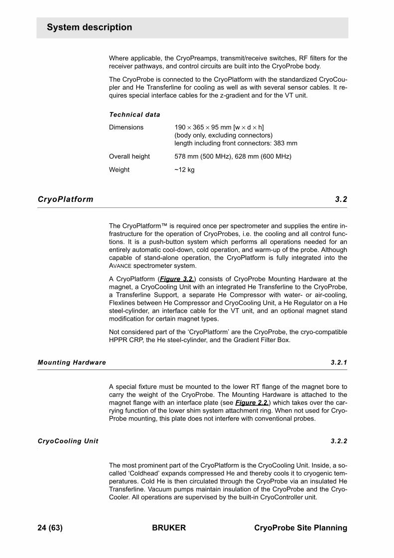
Where applicable, the CryoPreamps, transmit/receive switches, RF filters for thereceiver pathways, and control circuits are built into the CryoProbe body.
The CryoProbe is connected to the CryoPlatform with the standardized CryoCou-pler and He Transferline for cooling as well as with several sensor cables. It re-quires special interface cables for the z-gradient and for the VT unit.
Technical data
Dimensions 190 × 365 × 95 mm [w × d × h](body only, excluding connectors)length including front connectors: 383 mm
Overall height 578 mm (500 MHz), 628 mm (600 MHz)
Weight ~12 kg
CryoPlatform 3.2
0 The CryoPlatform™ is required once per spectrometer and supplies the entire in-frastructure for the operation of CryoProbes, i.e. the cooling and all control func-tions. It is a push-button system which performs all operations needed for anentirely automatic cool-down, cold operation, and warm-up of the probe. Althoughcapable of stand-alone operation, the CryoPlatform is fully integrated into theAVANCE spectrometer system.
A CryoPlatform (Figure 3.2.) consists of CryoProbe Mounting Hardware at themagnet, a CryoCooling Unit with an integrated He Transferline to the CryoProbe,a Transferline Support, a separate He Compressor with water- or air-cooling,Flexlines between He Compressor and CryoCooling Unit, a He Regulator on a Hesteel-cylinder, an interface cable for the VT unit, and an optional magnet standmodification for certain magnet types.
Not considered part of the ‘CryoPlatform’ are the CryoProbe, the cryo-compatibleHPPR CRP, the He steel-cylinder, and the Gradient Filter Box.
Mounting Hardware 3.2.1
A special fixture must be mounted to the lower RT flange of the magnet bore tocarry the weight of the CryoProbe. The Mounting Hardware is attached to themagnet flange with an interface plate (see Figure 2.2.) which takes over the car-rying function of the lower shim system attachment ring. When not used for Cryo-Probe mounting, this plate does not interfere with conventional probes.
CryoCooling Unit 3.2.2
The most prominent part of the CryoPlatform is the CryoCooling Unit. Inside, a so-called ‘Coldhead’ expands compressed He and thereby cools it to cryogenic tem-peratures. Cold He is then circulated through the CryoProbe via an insulated HeTransferline. Vacuum pumps maintain insulation of the CryoProbe and the Cryo-Cooler. All operations are supervised by the built-in CryoController unit.

CryoPlatform
CryoProbe Site Planning BRUKER 25 (63)
Controls on the CryoCooling Unit
Technical data: CryoCooling UnitDimensions 800 × 720 × 1300 mm [w × d × h]
Weight 400 kg
Electricity AC 230 V (1 phase) 50/60 Hz,500 W average, 1500 W peak,required external fuse upstream: T 10 A (T = time-lag fuse).
Acoustic noise max. 61 dB(A) 2 m distant (CryoCooling Unit only)
The CryoCooling Unit complies with overvoltage category II and its degree of pro-tection is IP20.
He Regulator
He Compressor
Transferline Support
CryoCooling Unit
Push buttons forwarm-up / cool-down
Magnet
HPPR CRP
He Transferline
CryoProbe
Vacuum tube
Magnet standpillar brace
He Hose
He steel-cylinder
Figure 3.2. A CryoPlatform™

26 (63) BRUKER CryoProbe Site Planning
System description
He Compressor 3.2.3
The He Compressor unit provides compressed He and electrical power to theColdhead inside the CryoCooling Unit.
Technical data
Dimensions (w × d × h in mm)
P/N O00245 (3 × 200 V AC, air-cooled) 550 × 550 ×=885P/N O00246 (3 × 200 V AC, water-cooled) 450 × 500 × 684P/N O00247 (3 × 400 V AC, water-cooled) 450 × 500 × 684
Weight (approx.)
P/N O00245 (3 × 200 V AC, air-cooled) 140 kgP/N O00246 (3 × 200 V AC, water-cooled) 120 kgP/N O00247 (3 × 400 V AC, water-cooled) 125 kg
Ambient operating temperature 5 to 28°C
Air humidity (relative) max. 90%
Electricity
line voltage (± 5%) P/N O00245 AC 200 V, 50/60 Hz, 3 phase,P/N O00246 AC 200 V, 50/60 Hz, 3 phase,P/N O00247 AC 380 - 415 V @ 50 Hz, 3 phase,
AC 460 - 480 V @ 60 Hz, 3 phase.operating current P/N O00245 25 A (110 A starting current)
P/N O00246 25 A (110 A starting current)P/N O00247 12 A (60 A starting current)
power requirement 9 kVApower consumptionmaximum 8.3 kW
steady state 7.5 kW
Pressure relief valve setting 27.3 bar (390 psi)
Cooling water requirement (P/N O00246 and P/N O00247 only)
minimum flow 7 L/min (420 L/hr)recommended flow 10 L/min (600 L/hr)pressure drop in He Compressor 1.6 bar (without calcification)recommended pressure 3.2 barmax. inlet pressure 7.0 barcooling power 7.5 kW (+ heat from opt. chiller)water temperature (at He Compressor inlet) 4 - 28°Crecommended water temperature 15°Cwater temperature (at He Compressor outlet) max. 17°C higher than at inletpH value 6.5 - 8.2hardness ≤ 200 mg CaCO3/Lmolybdate-reactive silica ≤ 50 mg/Lsuspended matter ≤ 10 mg/Lconnector type pipe thread 3/8”
Each cooling water connector is fitted with a complete set (male+female) ofself-sealing couplers that end in another pipe thread 3/8”.
Acoustic noise ca. 65 dB(A) 2 m distance

Cryo-compatible preamplifier assembly ‘HPPR CRP’
CryoProbe Site Planning BRUKER 27 (63)
Cryo-compatible preamplifier assembly ‘HPPR CRP’ 3.3
0 Although a CryoProbe has its own set of cold preamplifiers built-in, some HPPR functions such as RF fil-ters in the transmission path, probe tuning, and selection of the received signal must be handled externally by a modified HPPR CRP assembly. Besides being suited for the operation with CryoProbes, this HPPR CRP can be used with all conventional probes. An existing HPPR will be exchanged for an HPPR CRP (see "Compatibility" on page 9).
Technical dataData for TXI configuration (cover and 5 HPPR modules), an X-BB module is in-cluded by default:
Dimensions (w × d × h in mm) 260 × 350 × 420
Weight 25 kg
Software 3.4
0 The CryoController can be interfaced to a computer running Windows™ 95/NT4or later. Monitoring software is delivered with the CryoProbe System.
Figure 3.3. Cryo-compatible preamplifier assembly ‘HPPR CRP’
‘RF in’ fromCryoPreamps
1H CRP module
2H CRP module13C CRP module15N CRP module
conventional X-BB
transmit & receive,decoupling channel
transmit only,observe channel
CryoProbe powersupply on rear
e.g. for a TXI probe:

28 (63) BRUKER CryoProbe Site Planning
System description

CryoProbe Site Planning BRUKER 29 (63)
BRUKER contact 44000000
Submit your enquiries about CryoProbe sales and service to your local BRUKERrepresentation. Use the following address only if they cannot help you.
CryoProbe information 4.1
0 CryoProbe information head offices:
BRUKER AG BRUKER Instruments, Inc.Probe Department 44 Manning RoadIndustriestrasse 26 Billerica, MA 01821CH-8117 Fällanden U.S.A.Switzerland
phone: ++41-1-825 91 11 phone: ++1-978-667-9580fax: ++41-1-825 96 96 fax: ++1-978-667-0985e-mail: [email protected] e-mail: [email protected]: http://www.bruker.de www: http://www.bruker.com
CryoProbe service 4.2
0 CryoProbe service head offices:
BRUKER AG BRUKER CenterService Department BRUKER Instruments, Inc.Industriestrasse 26 15 Fortune DriveCH-8117 Fällanden Billerica, MA 01821Switzerland U.S.A.
phone: ++41-1-825 91 11 phone: ++1-978-667-9580, then press 2fax: ++41-1-825 96 96 fax: ++1-978-667-6168e-mail: [email protected] e-mail: [email protected]: http://www.bruker.de www: http://www.bruker.com
0

30 (63) BRUKER CryoProbe Site Planning
Bruker contact

CryoProbe Site Planning BRUKER 31 (63)
Related documents A1000000
The following documents contain further information.
CryoProbe Site Planning QuestionnaireA questionnaire for potential CryoProbe customers about their NMR laboratoryand spectrometer. BRUKER needs this information for tailoring the CryoProbe Sys-tem to the customer’s needs and for preparing its installation.
CryoProbe System Site Preparation Manual (P/N Z31553)This manual accompanies the Site Preparation Set which is delivered before oth-er devices are sent. After being installed by the customer, the set provides the in-frastructure for the actual CryoPlatform.
CryoProbe System User Manual (P/N Z31551)Describes the setup and operation of a CryoProbe system.
CryoProbe data sheetsRF power limits, sample temperature range etc. specific for the actual CryoProbe.
He Compressor technical manualThe operation manual is delivered with the He Compressor.
CRP RF Electronics Technical Manual (P/N Z31474)Describes the RF wiring between CryoProbe and spectrometer, explains how toconfigure the HPPR CRP, lists technical data, and contains service information forthe preamplifier system.

32 (63) BRUKER CryoProbe Site Planning
Related documents
initial setup relocateCryoPlatform
site planning
Site PlanningGuide
InstallationManual
UserManual
Site PlanningQuestionnaire
RF ElectronicsManual
He CompressorManual
Figure A.1. When to use which CryoProbe document
OperationSupporting
of CryoPlatform
document
power-upCryoProbe System
operateCryoProbe System
basic maintenance basic troubleshooting
power-downCryoProbe System
maintenance troubleshooting
mountCryoProbe
removeCryoProbe
mount conventionalprobe
swap CryoProbes
site preparation Site PreparationManual
CryoProbe Site Planning BRUKER 33 (63)
Building blocks for site planning B2000000
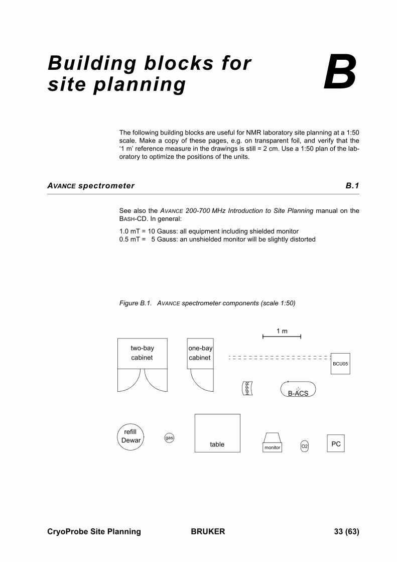
The following building blocks are useful for NMR laboratory site planning at a 1:50scale. Make a copy of these pages, e.g. on transparent foil, and verify that the‘1 m’ reference measure in the drawings is still = 2 cm. Use a 1:50 plan of the lab-oratory to optimize the positions of the units.
AVANCE spectrometer B.1
0 See also the AVANCE 200-700 MHz Introduction to Site Planning manual on theBASH-CD. In general:
1.0 mT = 10 Gauss: all equipment including shielded monitor 0.5 mT = 5 Gauss: an unshielded monitor will be slightly distorted
refillDewar
two-baycabinet
one-baycabinet
HPP
R
BCU05
gas
B-ACS
table monitor PCO2
1 m
Figure B.1. AVANCE spectrometer components (scale 1:50)

34 (63) BRUKER CryoProbe Site Planning
Building blocks for site planning
CryoProbe System B.2
0 Magnetic stray fieldsHe Compressor, He steel-cylinder, and optional water chiller have to be kept out-side the magnet’s 0.5 mT field. As a rule, all spectrometer and CryoProbe Systemcomponents should be as far away as possible from the magnets. In particular,the He steel-cylinder and its entire transport path must always be outside the0.5 mT range.
Legendopen space for ventilation
gas
HeCompr.
air-cool.
spac
e fo
rse
rvic
e
HeCompr.water-c.
spac
e fo
rse
rvic
e
Flexline (6 m)
Flexline (6 m)
Figure B.2. CryoProbe System components (scale 1:50)
CryoProbe
Cryo
CoolingU
nitCry
oC
oolin
gU
nit
CryoCoolingUnitCryo
Cooling
Unit

Building blocks for site planning
CryoProbe Site Planning BRUKER 35 (63)
CryoProbe in magnet B.3
0 Legend
5.0 mT for ultrashielded™ magnet0.5 mT for ultrashielded™ magnet5.0 mT for non-shielded magnet0.5 mT for non-shielded magnetmagnet helium turrets (refill turret: grey)sample changer foot (optional)sc
500
sc
0.75 m
1.30 m
1.50 m
3.20 m
Figure B.3. BRUKER 500 MHz magnet (scale 1:50)
1 m
36 (63) BRUKER CryoProbe Site Planning
Building blocks for site planning
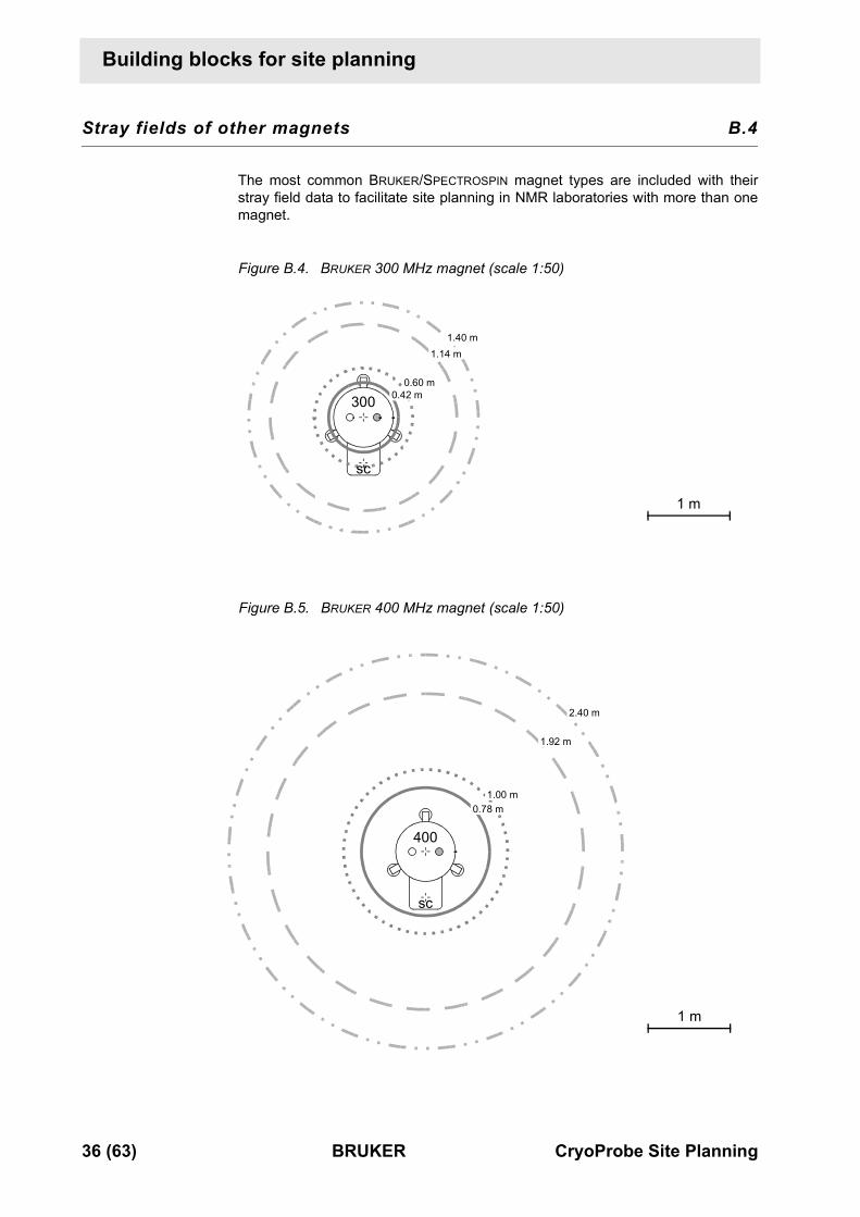
Stray fields of other magnets B.4
0 The most common BRUKER/SPECTROSPIN magnet types are included with theirstray field data to facilitate site planning in NMR laboratories with more than onemagnet.
300
sc
0.42 m0.60 m
1.14 m1.40 m
1 m
Figure B.4. BRUKER 300 MHz magnet (scale 1:50)
400
sc
0.78 m1.00 m
1.92 m
2.40 m
Figure B.5. BRUKER 400 MHz magnet (scale 1:50)
1 m

Building blocks for site planning
CryoProbe Site Planning BRUKER 37 (63)
0
600
sc
0.9 m
1.80 m
1.90 m
4.10 m
Figure B.6. BRUKER 600 MHz magnet (scale 1:50)
1 m

38 (63) BRUKER CryoProbe Site Planning
Building blocks for site planning
700
1.70 m
2.50 m
Figure B.7. BRUKER 700 MHz magnet (scale 1:50)
1 m

Building blocks for site planning
CryoProbe Site Planning BRUKER 39 (63)
Figure B.8. BRUKER 800 MHz magnet (scale 1:50)
2.80 m2.85 m
1.55 m
800
6.10 m

40 (63) BRUKER CryoProbe Site Planning
Building blocks for site planning
3.65 m
900
Figure 0.1. BRUKER 900 MHz magnet (scale 1:50)0.5 mT line not shown (Radius 7.85 m)

CryoProbe Site Planning BRUKER 41 (63)
Conversion of metric units C
3000000
1 bar ≡=0.1 MPa 1 Pa ≡ 0.01 mbar
1 bar ≈ 14.5 psi 1 psi ≡ 68.95 mbar
1 bar ≈ 1.02 kgf/cm2 1 kgf/cm2 ≈ 0.98 bar
1 kg ≈ 2.2 lb 1 lb ≡ 0.4536 kg
1 mm ≈ 0.04 inch 1 inch ≡=25.4 mm
1 m ≈ 3.28 feet 1 foot ≡ 0.3048 m
1 Nm ≈ 8.85 lbf-inch 1 lbf-inch ≈ 0.113 Nm
1 L (liter) ≈ 0.264 gallon (U.S.) 1 gallon (U.S.) ≈ 3.79 L
1 L (liter) ≈ 0.220 gallon (Brit.) 1 gallon (Brit.) ≈ 4.55 L
1 kWh ≈ 3.6 MJ 1 MJ ≈ 0.278 kWh
1 kWh ≈ 3412 btu 1 btu ≈ 0.293 Wh
1 mT ≡=10 Gauss 1 Gauss ≡=0.1 mT
°C to °F: °F to °C:
Table C.1. Conversion between °C and °F temperature scales
°C -30 -20 -10 0 10 20 30 40 50 60 70 80 90 100 110
°F -22 -4 14 32 50 68 86 104 122 140 158 176 194 212 230
T°F T°C 1.8×( ) 32+= T°C T°F 32–( ) 1.8⁄=

42 (63) BRUKER CryoProbe Site Planning
Conversion of metric units

CryoProbe Site Planning BRUKER 43 (63)
Frequently asked questions D
4000000
System configuration D.1
0
Which CryoProbe types are or will be available?
Please ask your local BRUKER representative for the current choice of probes andaccessories.
Can the CryoProbe be used with any magnet and spectrometer?
Any standard bore magnet can host a CryoProbe. However, specifications areguaranteed only if the B0 homogeneity of the magnet suffices (i.e. if it allows toreach specifications with recent conventional BRUKER probes) and if a BOSS-2shim system is present. One mechanical restriction is given by the clearance be-low the magnet between shim system and floor that is needed for insertion of theCryoProbe. Another restriction can be vacuum valves, drop-off plates or the like atthe magnet dewar bottom. Ask your BRUKER representative for compatibilities.
Since the CryoProbe System must interact with an AVANCE spectrometer, it can-not be connected to other spectrometer types.
How much space is required by the CryoProbe System?
Rough estimate: 6 m2. If the He Compressor is located in an adjacent room, about4 m2 suffices.
Can conventional probes still be used on a spectrometer that isequipped with a CryoProbe System?
Yes. A conventional probe can be connected to the spectrometer as usual. How-ever, certain special probes or auxiliary devices might cause geometrical conflictswhich can be easily and quickly resolved by removing the guiding rods of the Cry-oProbe Mounting Hardware.
Is a VT gas cooler recommended?
The CryoProbe can be operated with and without a VT gas cooler. Currently, onlythe BCU05 is approved. It is needed for measurements below room temperatureand slightly above room temperature (i.e. up to 2 - 5°C higher). A nitrogen evapo-rator must not be used.

44 (63) BRUKER CryoProbe Site Planning
Frequently asked questions
NMR operation D.2
0
Do any experimental restrictions result from the high Q factor ofthe CryoProbe?
The Q factor is optimized for each NMR coil assembly to minimize any problemswith ring-down times, radiation damping, or excitation bandwidths, still allowingmaximum gain in sensitivity.
Is the CryoProbe more sensitive to external disturbances?
Just in proportion to its higher signal-to-noise ratio.
Is it possible to measure water samples?
Yes.
Is it possible to measure samples with a high salt concentration?
Yes, but the usual restrictions apply: the higher electrical conductivity of a salt so-lution reduces the penetration depth of the RF, spoils the Q factor of the reso-nance circuit, and introduces additional spectral noise.
Is shimming more difficult?
Manual shimming is not much different from conventional probes. There are noparticularly strong shim gradients to be set. Gradient shimming is possible.
Does the user have to modify the pulse programs?
Usually not. Of course, those conventional pulse sequences that are optimized forhigh signal-to-noise and suppression of spurious signals are still highly recom-mended.
Which experimental parameters do I have to be careful with to avoid damage to the CryoProbe?
Maximum RF power. In general, a CryoProbe requires significantly less RF powerto achieve the same pulse lengths as conventional probes.
Does the CryoProbe change its characteristics during long decoupling or spin-lock periods?
Long decoupling or spin-lock periods tend to warm-up the RF components in anyprobe. For such experiments, it might be advisable to equilibrate the CryoProbewith dummy scans before data acquisition starts. Significant changes in tuning &matching are not to be expected.
Do experimental parameters like shims and pulse angles changeafter a warm-up/cool-down cycle? Is the sensitivity preserved?
Parameters like shim, tuning & matching, or pulse angles are constant with minorvariations as known from conventional probes. Experience so far indicates thatthe excellent sensitivity of the CryoProbe does not suffer from repeated warm-up/cool-down cycles if the recommended operation procedures are obeyed.

Frequently asked questions
CryoProbe Site Planning BRUKER 45 (63)
Is the CryoProbe performance stable and reproducible in the longterm?
Experience so far: Yes.
Will the CryoProbe be damaged if the cryocooling is accidentally interrupted during a measurement?
An interrupt in the cryocooling should not break the CryoProbe.
Basic aspects D.3
Why does the CryoProbe have such a high signal-to-noise ratio?
Thermal noise is greatly reduced by cooling the NMR coil assembly and thepreamplifiers to cryogenic temperatures. Furthermore, the low electrical resis-tance enhances the Q factor of all resonant circuits in the probe and its filters.
What is inside a CryoProbe?
The CryoProbe contains a tuned NMR coil assembly, a gradient coil, preamplifierelectronics, and supervisor electronics inside a vacuum isolated dewar. Cold heli-um gas is circulated to cool the NMR coil assembly and the preamplifier electron-ics while the sample is kept at ambient temperature. All the common probefunctions needed for RF transmission, tuning, gradient pulses, and VT gas ductare built into the CryoProbe, while the sample lift and spinning are provided asusual by the shim upper part.
What does the NMR coil look like?
The NMR coil assembly generates a transverse B1-field for the tuned frequencies.Its material, geometry, and associated RF circuits are optimized for each type ofprobe. Details of the coil assembly design are proprietary knowledge of BRUKER.
What is the helium consumption of the CryoProbe System?
No liquid helium is used whatsoever. Helium gas (He) is needed for the initial fill ofthe closed-loop system and for flushing the system before each cool-down. Dur-ing cold operation, the He consumption is negligible. A standard He steel-cylinder(50 L) can last for more than 40 cool-down/warm-up cycles.
Can the user repair any part of the CryoProbe?
No, there are no user-serviceable parts on or inside a CryoProbe. Essential partsof a CryoProbe may easily be broken during opening or closing. Therefore, ser-vice actions on the CryoProbe can only be done at the factory. BRUKER warrantyexpires if the CryoProbe is opened by unauthorized personnel.

46 (63) BRUKER CryoProbe Site Planning
Frequently asked questions

CryoProbe Site Planning BRUKER 47 (63)
Glossary E5000000
Adsorber
Device inside the He Compressor that adsorbs oil and other impurities from thecirculated helium gas (He).
BBIS
BRUKER Board Information System
Coldhead
Cools down compressed He in a Gifford-McMahon expansion cycle. Its two stag-es are the primary cooling devices of the CryoCooler.
CryoController
Controls all functions of CryoProbe and CryoPlatform. It communicates with thespectrometer and is located inside the CryoCooling Unit.
CryoCooler
The CryoCooler cools and circulates the cold He. It consists of the Coldhead in acold box unit and a gas circulation unit with valves and gauges. In contrast, theterm ‘CryoCooling Unit’ denotes the whole cabinet including vacuum system etc.
CryoCooling Unit
A cabinet that contains the CryoCooler, the CryoController, a vacuum system,and the He Transferline. It is labelled ‘CryoPlatform’ because it is the most promi-nent part of a CryoPlatform.
CryoCoupler
Standardized interface between the He Transferline from the CryoCooling Unitand the CryoProbe that connects both forward and backward streams of cold Heat once.
CryoPlatform
All parts needed for operating a CryoProbe with a spectrometer, i.e. CryoProbeMounting Hardware, CryoCooling Unit, He Compressor, He Transferline, Trans-ferline Support, VT Interface Box, and optional magnet stand modifications. How-ever, the HPPR CRP, and the He steel-cylinder are not parts of the CryoPlatform.
CryoPreamp
A cryogenically cooled preamplifier module inside the CryoProbe housing. Thereis a frequency-specific preamp module for each channel of a CryoProbe. A Cryo-Preamp cannot be separated from its CryoProbe. It always requires an additionalexternal HPPR assembly, the cryo-compatible HPPR CRP.
48 (63) BRUKER CryoProbe Site Planning
Glossary
CryoProbeAlthough the CryoProbe System is often colloquially referred to as ‘CryoProbe’,this term designates the probe part only.
CryoProbe RF UnitAll CryoPreamps, transmit/receive switches, RF filters for the receiver pathways,and control circuits that are built into the CryoProbe body.
CryoProbe SystemA CryoProbe and all components necessary for its operation.
CryoToolA software interface for monitoring the CryoProbe System parameters. It runs ona separate laptop or PC.
Dump ToolA short gas tube with a silencer. This service tool is used to release the He supplypressure at the joint between He Regulator and He Hose before the He steel-cyl-inder is exchanged.
FlexlinesA pair of flexible tubes that guide pressurized He at ambient temperature from theHe Compressor to the CryoCooling Unit and back. Pressurized He at 15 to 30 baris kept inside these gas tubes at all times - even when disconnected! They areisolated to reduce thermal disturbances and acoustic noise.
Gradient Filter BoxSmall box to interface a standard BRUKER gradient cable to the CryoProbe.
HeGaseous helium of high purity, used for cryogenic cooling of the CryoProbe.
He CompressorWarm He from the CryoProbe is routed through the CryoCooling Unit to the HeCompressor. The compressed He is sent back to the CryoCooling Unit, circulatingin a closed loop.
The He Compressor serves two functions: (1) It provides the primary energy (inform of compressed He) for the cooling action of the CryoCooler. (2) It circulatesthe He between the CryoCooling Unit and the CryoProbe, providing the transportof ‘the cold’ to the CryoProbe.
He HoseFlexible hose for pressurized helium gas that connects the He steel-cylinder withthe CryoCooling unit.
He RegulatorA pressure reduction valve with two gauges that is mounted on the He steel-cylin-der.

Glossary
CryoProbe Site Planning BRUKER 49 (63)
He steel-cylinder
Standard helium gas steel-cylinder (50 L) for the initial fill of the CryoProbe Sys-tem and for flushing the closed-loop He cycle before each cool-down.
He Transferline
Isolated tube through which the cold He from the CryoCooling Unit flows to theCryoProbe. The He Transferline is part of the CryoCooling Unit and cannot be de-tached from the cabinet. It goes in parallel with the vacuum tube.
HPPR CRP
Cryo-compatible preamplifier assembly located close to the magnet that is a stackof frequency-specific preamplifier modules, a cover module, and a base plate. To-gether with the CryoPreamp inside the CryoProbe, the HPPR CRP forms theNMR preamplifier system. Although it looks very similar to a conventional HPPR,its components are modified for interacting with both a CryoProbe or a conven-tional probe. When operating with a CryoProbe, the HPPR CRP performs the RFfiltering in the transmitter pathway, selects the received signal, handles the probetuning, and supplies the CryoProbe electronics. An HPPR CRP can be used withconventional probes just like a conventional HPPR.
HPPRtool
Software tool on the spectrometer workstation Unix/NT level that interacts with allHPPR types.
Magnet stand pillar braces
Horizontal metal braces that connect the anti-vibration stands of certain BRUKER/SPECTROSPIN magnets. Two braces at the magnet front must be replaced bycranked ones to enlarge the gap for introducing the CryoProbe.
Mounting Hardware
Special assembly that is attached to the magnet bottom to hold the CryoProbe inposition.
PIC
Probe Identification and Control system that transmits probe-specific data to thespectrometer.
Pneumatic gas
Usually compressed air or nitrogen gas at 4.5-6 bar for the operation of the pneu-matic valves inside the CryoCooling Unit.
Protection Cap
A white plastic cap to protect the CryoProbe sample cavity against dirt duringtransport, testing, or storage.
Q factor
The quality factor Q is a measure of the efficiency of reactive devices such as in-ductors, capacitors, or resonant circuits.

50 (63) BRUKER CryoProbe Site Planning
Glossary
RF
Radio frequency
Transferline Support
A heavy upright cylinder that supports the He Transferline about halfway betweenthe CryoCooling Unit and the CryoProbe. It also isolates the CryoProbe from me-chanical vibrations of the CryoCooling Unit.
Tuning Adapter
Removable assembly of tuning and matching knobs. A VT gas connector is alsoincluded. Its geometry depends on the type of CryoProbe.
Tuning Tool
A special blue screwdriver to operate the tuning and matching knobs of a Cryo-Probe’s Tuning Adapter.
UniTool
Software tool on the CryoProbe System laptop to interact with the CryoControlleror other units.Under Windows NT Start->BrukerAG->UniTool.
UPS
Uninterruptable Power Supply, a kind of battery that compensates for fluctuationsand interruptions in the mains.
Vacuum Adapter
Adapter for evacuation of the CryoProbe insulation, connected to its bottom. Itfeatures an airtight actuator screw to move the CryoProbe’s Vacuum Plug in andout.
Vacuum Plug
A small metal plug with an o-ring and an inner thread that closes the CryoProbevacuum chamber against moisture and dirt.
Vacuum tube
Flexible metal vacuum tube that connects the CryoProbe isolation to the vacuumsystem inside the CryoCooling Unit. It is parallel to the He Transferline.
Vacuum system
Vacuum pumps and valves that evacuate the dewar insulations of CryoProbe, HeTransferline, and CryoCooler. Located inside the CryoCooling Unit.
VT gas
Usually nitrogen gas or dry air at a controlled variable temperature that flowsthrough a probe to heat or cool the sample. Its function must not be confused withthe ‘pneumatic gas’ used for operating valves inside the CryoCooling Unit or withthe helium gas circulated through the CryoProbe for cryogenic cooling.

Glossary
CryoProbe Site Planning BRUKER 51 (63)
VT Interface BoxA small box with two cables which interfaces heater and temperature sensor be-tween CryoProbe and VT unit.
VT unitA device that controls the flow and temperature of the VT gas, e.g. a B-VT3000.
Water chillerThe water-cooled versions of the He Compressor require cooling water to remove7.5 kW of heat. A water chiller is recommended if no closed cycle cooling water isavailable in the laboratory building.

52 (63) BRUKER CryoProbe Site Planning
Glossary

CryoProbe Site Planning BRUKER 53 (63)
Figures
1 Introduction 5Figure 1.1. The CryoProbe™ System ..................................................... 6
2 Site planning 9Figure 2.1. Site planning example ........................................................ 10Figure 2.2. Interface plate of Mounting Hardware to magnet ................ 11Figure 2.3. Required access to the magnet bottom ............................... 14Figure 2.4. Flexibility of the He Transferline ......................................... 15Figure 2.5. Siting proposal for an air-cooled He Compressor ................ 20
3 System description 23Figure 3.1. A CryoProbe™ ................................................................... 23Figure 3.2. A CryoPlatform™ ............................................................... 25Figure 3.3. Cryo-compatible preamplifier assembly ‘HPPR CRP’ .......... 27
4 Bruker contact 29
A Related documents ............................................. 31Figure A.1. When to use which CryoProbe document ........................... 32
B Building blocks for site planning ....................... 33Figure B.1. AVANCE spectrometer components (scale 1:50) .................. 33Figure B.2. CryoProbe System components (scale 1:50) ...................... 34Figure B.3. BRUKER 500 MHz magnet (scale 1:50) ................................ 35Figure B.4. BRUKER 300 MHz magnet (scale 1:50) ................................ 36Figure B.5. BRUKER 400 MHz magnet (scale 1:50) ................................ 36Figure B.6. BRUKER 600 MHz magnet (scale 1:50) ................................ 37Figure B.7. BRUKER 700 MHz magnet (scale 1:50) ................................ 38Figure B.8. BRUKER 800 MHz magnet (scale 1:50) ................................ 39Figure 0.1. BRUKER 900 MHz magnet (scale 1:50) ................................ 40
C Conversion of metric units ................................. 41
D Frequently asked questions ............................... 43
E Glossary .............................................................. 47

54 (63) BRUKER CryoProbe Site Planning
Figures

CryoProbe Site Planning BRUKER 55 (63)
Tables
1 Introduction 5
2 Site planning 9Table 2.1. Compatible B-ACS 60/120 holders ................................. 12Table 2.2. Access space ................................................................ 14Table 2.2. Common outlet types on He gas steel-cylinders ............. 22
3 System description 23
4 Bruker contact 29
A Related documents 31
B Building blocks for site planning 33
C Conversion of metric units 41Table C.1. Conversion between °C and °F temperature scales ........ 41
D Frequently asked questions 43
E Glossary 47

56 (63) BRUKER CryoProbe Site Planning
Tables

CryoProbe Site Planning BRUKER 57 (63)
Index
A
access to magnet ...................................................................................... 9, 14, 43accessories ......................................................................................................... 43acoustic noise ......................................................................................... 16, 18, 48adsorber ........................................................................................................ 16, 47air compressor .................................................................................................... 21air conditioning ............................................................................................ 17 – 19altitude................................................................................................................. 20antifreeze ............................................................................................................ 21
B
BBIS .................................................................................................................... 47BCU05 gas cooler ................................................................................... 18, 21, 43BOSS-2......................................................................................................... 10, 43building blocks for site planning .......................................................................... 33
C
calcification.................................................................................................... 20, 26Coldhead................................................................................................. 24, 26, 47compatibility .......................................................................................................... 9
conventional probes...................................................................................... 43magnet...................................................................................................... 9, 43Radiation Damping Control Unit ................................................................... 13shim system.................................................................................................. 10software ........................................................................................................ 13spectrometer............................................................................................. 9, 43spinner stator ................................................................................................ 10
computer ............................................................................................................. 27condensation of water ......................................................................................... 21conventional probes............................................................................................ 49cooling water
chemical properties................................................................................. 20, 26closed cycle .................................................................................................. 20
CryoController ............................................................................................... 24, 47CryoCooler .................................................................................................. 47 – 48CryoCooling Unit ................................................................................................. 47
description .................................................................................................... 24distance to magnet ....................................................................................... 17siting ....................................................................................................... 15, 17technical data................................................................................................ 25waste heat .................................................................................................... 19
CryoCoupler .................................................................................................. 24, 47CryoPlatform ....................................................................................................... 47
description .................................................................................................... 24

58 (63) BRUKER CryoProbe Site Planning
Index
multiple installations...................................................................................... 16terminology ..................................................................................................... 5
CryoPreamp .......................................................................................... 23, 47 – 48CryoProbe ........................................................................................................... 48
available types .............................................................................................. 43cavity............................................................................................................. 21default orientation ......................................................................................... 10description .................................................................................................... 23spectroscopic handling ................................................................................... 5
CryoProbe RF Unit .............................................................................................. 48CryoProbe System .......................................................................................... 6, 48
description .................................................................................................... 23subunits .......................................................................................................... 5
D
dew point............................................................................................................. 21dimensions .......................................................................................................... 16drawing of laboratory............................................................................... 13, 22, 33duct ..................................................................................................................... 20dust ............................................................................................................... 19, 21
E
electricity ............................................................................................................. 18example of an NMR lab......................................................................................... 9excitation bandwidth............................................................................................ 44exhaust air........................................................................................................... 20experimental restrictions ..................................................................................... 44external disturbance............................................................................................ 44
F
FAQs ................................................................................................................... 43Flexlines .............................................................................................................. 48
bending ......................................................................................................... 18extended ....................................................................................................... 15
frequently asked questions ................................................................................. 43fresh air ....................................................................................................... 18 – 20fuses
CryoCooling Unit..................................................................................... 18, 25He Compressor............................................................................................. 19
G
Gauss.................................................................................................................. 41GHe..................................................................................................................... 48GHe cylinder ..................................................................................... 15, 34, 45, 49
exchange of .................................................................................................. 22Gifford-McMahon cycle ....................................................................................... 47glossary............................................................................................................... 47glycol ................................................................................................................... 21gradient shimming............................................................................................... 44guiding rod .................................................................................................... 11, 43

Index
CryoProbe Site Planning BRUKER 59 (63)
H
He Compressor ................................................................................................... 48air-cooled .................................................................................. 16 – 18, 20, 26cooling .................................................................................................... 20, 26description .................................................................................................... 26electricity....................................................................................................... 19remote location ............................................................................................. 15siting ............................................................................................................. 18technical manual........................................................................................... 31transformer ................................................................................................... 19ventilation...................................................................................................... 16waste heat .............................................................................................. 16, 19water pressure drop................................................................................ 20, 26water-cooled ........................................................................................... 17, 26
He Transferline.................................................................................................... 49flexibility .................................................................................................. 15, 17
heliumcharging hose ............................................................................................... 21consumption ........................................................................................... 22, 45cylinder ................................................................................. 15, 22, 34, 45, 49Flexlines........................................................................................................ 48flushing ................................................................................................... 45, 49gas regulator................................................................................................. 21He Transferline ............................................................................................. 49loss ............................................................................................................... 22
HPPR CRP.......................................................................................................... 49description .................................................................................................... 27
HPPRtool ............................................................................................................ 49humidity................................................................................................. 19 – 20, 26
I
indoor use ........................................................................................................... 13information head office........................................................................................ 29interface cables ................................................................................................... 24Interface plate ..................................................................................................... 11
M
magnet ................................................................................................................ 17air suspension............................................................................................... 21and Mounting Hardware ............................................................................... 24B0 homogeneity............................................................................................ 43building blocks .............................................................................................. 36center............................................................................................................ 15drop-off plate............................................................................................. 9, 43interface plate ............................................................................................... 11lower RT flange............................................................................................. 24orientation ..................................................................................................... 22pillar braces .............................................................................................. 9, 49pit ................................................................................................ 9, 14, 17 – 18refill ................................................................................................... 14, 18, 22vacuum valve............................................................................................ 9, 43

60 (63) BRUKER CryoProbe Site Planning
Index
mains................................................................................................................... 18cable ............................................................................................................. 18interrupt................................................................................................... 19, 50spectrometer backpanel ............................................................................... 18
measurement time ................................................................................................ 5mechanical vibrations.............................................................................. 15, 17, 50metric units.......................................................................................................... 41monitor ................................................................................................................ 33Mounting Hardware......................................................................................... 9, 49
description .................................................................................................... 24guiding rod .................................................................................................... 11interface plate ............................................................................................... 11orientation ............................................................................................. 10 – 11
MPa..................................................................................................................... 41
N
nitrogenevaporator..................................................................................................... 43gas ........................................................................................................ 49 – 50
NMR coil assembly ............................................................................................. 23
O
operating temperature......................................................................................... 26
P
PIC ...................................................................................................................... 49pipe thread .................................................................................................... 20, 26pneumatic gas............................................................................................... 21, 49power failure........................................................................................................ 19preamplifier ......................................................................................................... 49
cryo-compatible HPPR CRP......................................................................... 27integrated................................................................................................ 23, 47wiring ............................................................................................................ 31
pressure relief valve ............................................................................................ 26psi........................................................................................................................ 41pulse program ..................................................................................................... 44
Q
Q factor ......................................................................................................... 44, 49questionnaire........................................................................................... 17, 22, 31
R
radiation damping.......................................................................................... 13, 44radiator ................................................................................................................ 20RDCU.................................................................................................................. 13regulator for He gas ............................................................................................ 21RF ....................................................................................................................... 50
filter ................................................................................................. 24, 48 – 49

Index
CryoProbe Site Planning BRUKER 61 (63)
power limits................................................................................................... 31ring for cooling/heating the shim system............................................................. 10ring-down ............................................................................................................ 44room temperature................................................................................................ 19
S
safety warm-up.................................................................................................... 21sample
high salt ........................................................................................................ 44low concentration............................................................................................ 5safety ............................................................................................................ 21temperature .............................................................................................. 5, 31water ............................................................................................................. 21
sample changer............................................................................................. 18, 35Schuko ................................................................................................................ 18service
annual ........................................................................................................... 16headoffice ..................................................................................................... 29
shim systemcompatibility .................................................................................................. 10reorientation.................................................................................................. 10ring for cooling/heating ................................................................................. 10spinner stator ................................................................................................ 10
shimming............................................................................................................. 44signal-to-noise............................................................................................... 23, 44site planning sequence ....................................................................................... 17small laboratory................................................................................................... 16software......................................................................................................... 27, 49space requirement .............................................................................................. 43spectral noise ...................................................................................................... 44spectrometer ......................................................................................................... 9spinner stator ...................................................................................................... 10stability
NMR experiment....................................................................................... 5, 16stray field................................................................................................. 14, 21, 34supplies ............................................................................................................... 18
T
Transferline Support............................................................................................ 50dimensions.................................................................................................... 17siting ....................................................................................................... 15, 17
transformer.......................................................................................................... 19transmit/receive switch.................................................................................. 24, 48tuning & matching ............................................................................................... 49
U
UPS............................................................................................................... 10, 19user manual ........................................................................................................ 31

62 (63) BRUKER CryoProbe Site Planning
Index
V
vacuumpump............................................................................................................. 24system .......................................................................................................... 50tube............................................................................................................... 50
ventilation ............................................................................................................ 34VT gas........................................................................................................... 21, 50
cooler ............................................................................................................ 43heater............................................................................................................ 51interrupt......................................................................................................... 21
VT interface cable ............................................................................................... 51VT unit................................................................................................................. 51
W
waste heat............................................................................................. 16 – 17, 51water chiller ................................................................................................... 20, 51
connector, self-sealing.................................................................................. 26flow ......................................................................................................... 20, 26siting ............................................................................................................. 18
water sample....................................................................................................... 44weight.................................................................................................................. 16Windows 95/NT................................................................................................... 27
X
XWIN-NMR ......................................................................................................... 13

CryoProbe Site Planning BRUKER 63 (63)
Lastpage
End of Document