Embed Size (px)
Citation preview
Cryocooler Disturbances Reduction with Single and MultipleAxis Active/Passive
Vibration Control Systems
Eric M. Flint, Patrick Flannery, Michael Evert, Eric AndersonCSA Engineering, Inc.2565 Leghorn StreetMountain View, CA
Proceedings of the SPIE Conference # 3989Paper # 64
Newport Beach, CAMarch 6-9

Cryocooler Disturbance Reduction with Single and Multiple AxisActive/Passive Vibration Control Systems
Eric Flint*, Patrick Flannery, Michael Evert, Eric Anderson
CSA Engineering, 2565 Leghorn St., Mountain View, CA 94043
ABSTRACTCryocoolers are well known sources of harmonic disturbance forces. In this paper two miniaturized, add-on,vacuum compatible, active vibration control systems for cryocoolers are discussed. The first, called VIS6, isan active/passive isolation hexapod and has control authority in all six degrees of freedom. This capability isdesirable when reduction of all cryocooler disturbance loads, including the radial loads, is required. Each ofthe six identical hexapod struts consists of a miniature moving coil electromagnetic proof mass actuator,custom piezoelectric wafer load cell, viscoelastic passive isolation stage, and axial end flexures. The first fivedisturbance tones are reduced over a bandwidth of 250 Hz using a filtered-x least mean square algorithm. Load reductions of 30-40 dB were measured both axially and radially. The second system, called VRS1, is apure active control system designed to reduce axial expander head disturbance loads. It works on the basis ofa counter-force developed from an electromagnetic proof mass actuator. Error signals are provided from acommercial accelerometer to a standalone digital signal processor, on which a filtered-x least means squarecontrol algorithm is implemented. Over the 500 Hz control bandwidth, the 11 disturbance tones werereduced on between 14 to 40 dB.
Keywords: Vibration isolation, active control, reaction mass actuators, cryocoolers, piezoelectric wafer loadcell
1.0 INTRODUCTION
Infrared sensors for earth observation, missile seekers, magnetic resonance imaging devices, advancedtelecommunication circuitry, etc. can all depend on cryocoolers to maintain their extremely low operatingtemperatures (typically 77 Kelvin or lower). While cryocoolers offer certain advantages with regard to sizeand volume versus passive cooling methods, they can also have certain negative side effects. The side effectof interest to this paper is the tendency of cryocoolers to generate vibration disturbances that can perturbthe operation of the system being cooled, cause blurring of images, etc. These disturbances are caused by avariety of mechanisms including the movement of the pistons in the compressor, residual misbalancebetween the opposed compressors, motion of the regenerator in the expander, and resulting gas movement,volume changes and local expansion of expander walls.
Cryocooler disturbances are typically tonal. Normally multi-harmonic in nature, their strength typicallyscales with the rate of heat removal desired. The primary tone corresponds to the frequency of cryocooleroperation. These issues have traditionally been addressed through system level configuration of opposedcompressors and specialized drive electronics. New cryocooler technologies, such as pulse tubes and thosebased on turbomachinery, also show some promise of reducing undesirable vibrations.
Other approaches have also been developed, by CSA (Anderson et al, 1999) and others, that use activecontrol to achieve extremely low vibration levels. This particular paper focuses on two recently developedsystems designed as drop in solutions to reduce unwanted cryocooler disturbances. The first, VIS6, is a full sixdegree of freedom active isolation system. The second system, VRS1, is a more traditional active, singleaxis, inertial/counter-force control system.
*Correspondence: Email: [email protected]; www.csaengineering.com; Telephone: (650) 210-9000, Fax: (650)210-9001
2. BACKGROUND: CRYOCOOLER DISTURBANCES
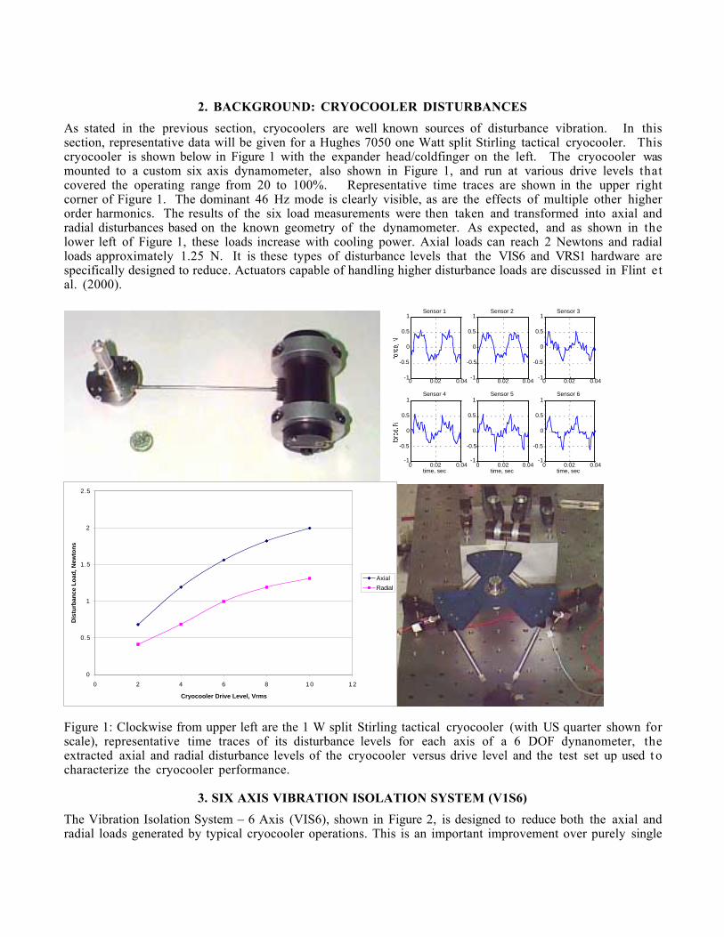
As stated in the previous section, cryocoolers are well known sources of disturbance vibration. In thissection, representative data will be given for a Hughes 7050 one Watt split Stirling tactical cryocooler. Thiscryocooler is shown below in Figure 1 with the expander head/coldfinger on the left. The cryocooler wasmounted to a custom six axis dynamometer, also shown in Figure 1, and run at various drive levels thatcovered the operating range from 20 to 100%. Representative time traces are shown in the upper rightcorner of Figure 1. The dominant 46 Hz mode is clearly visible, as are the effects of multiple other higherorder harmonics. The results of the six load measurements were then taken and transformed into axial andradial disturbances based on the known geometry of the dynamometer. As expected, and as shown in thelower left of Figure 1, these loads increase with cooling power. Axial loads can reach 2 Newtons and radialloads approximately 1.25 N. It is these types of disturbance levels that the VIS6 and VRS1 hardware arespecifically designed to reduce. Actuators capable of handling higher disturbance loads are discussed in Flint etal. (2000).
0 0.02 0.04-1
-0.5
0
0.5
1Sensor 1
0 0.02 0.04-1
-0.5
0
0.5
1Sensor 2
0 0.02 0.04-1
-0.5
0
0.5
1Sensor 3
0 0.02 0.04-1
-0.5
0
0.5
1Sensor 4
time, sec0 0.02 0.04
-1
-0.5
0
0.5
1Sensor 5
time, sec0 0.02 0.04
-1
-0.5
0
0.5
1Sensor 6
time, sec
0
0.5
1
1.5
2
2.5
0 2 4 6 8 1 0 1 2
Cryocooler Drive Level, Vrms
Dis
turb
ance
Lo
ad, N
ewto
ns
Axial
Radial
Figure 1: Clockwise from upper left are the 1 W split Stirling tactical cryocooler (with US quarter shown forscale), representative time traces of its disturbance levels for each axis of a 6 DOF dynanometer, theextracted axial and radial disturbance levels of the cryocooler versus drive level and the test set up used t ocharacterize the cryocooler performance.
3. SIX AXIS VIBRATION ISOLATION SYSTEM (V1S6)
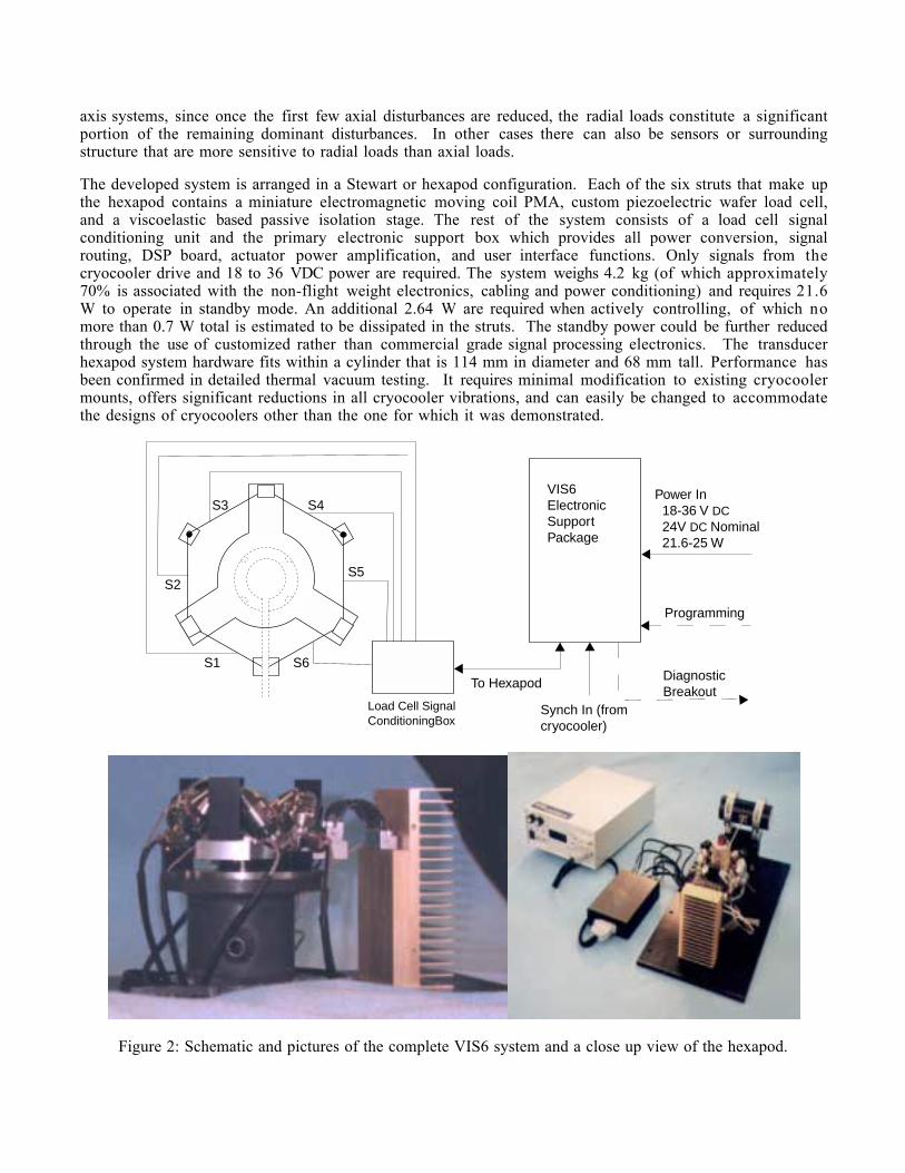
The Vibration Isolation System – 6 Axis (VIS6), shown in Figure 2, is designed to reduce both the axial andradial loads generated by typical cryocooler operations. This is an important improvement over purely single
axis systems, since once the first few axial disturbances are reduced, the radial loads constitute a significantportion of the remaining dominant disturbances. In other cases there can also be sensors or surroundingstructure that are more sensitive to radial loads than axial loads.
The developed system is arranged in a Stewart or hexapod configuration. Each of the six struts that make upthe hexapod contains a miniature electromagnetic moving coil PMA, custom piezoelectric wafer load cell,and a viscoelastic based passive isolation stage. The rest of the system consists of a load cell signalconditioning unit and the primary electronic support box which provides all power conversion, signalrouting, DSP board, actuator power amplification, and user interface functions. Only signals from thecryocooler drive and 18 to 36 VDC power are required. The system weighs 4.2 kg (of which approximately70% is associated with the non-flight weight electronics, cabling and power conditioning) and requires 21.6W to operate in standby mode. An additional 2.64 W are required when actively controlling, of which nomore than 0.7 W total is estimated to be dissipated in the struts. The standby power could be further reducedthrough the use of customized rather than commercial grade signal processing electronics. The transducerhexapod system hardware fits within a cylinder that is 114 mm in diameter and 68 mm tall. Performance hasbeen confirmed in detailed thermal vacuum testing. It requires minimal modification to existing cryocoolermounts, offers significant reductions in all cryocooler vibrations, and can easily be changed to accommodatethe designs of cryocoolers other than the one for which it was demonstrated.
Power In 18-36 V DC 24V DC Nominal 21.6-25 W
Synch In (fromcryocooler)
DiagnosticBreakout
VIS6ElectronicSupportPackage
Load Cell SignalConditioningBox
To Hexapod
S1
S2
S3 S4
S5
S6
Programming
Figure 2: Schematic and pictures of the complete VIS6 system and a close up view of the hexapod.
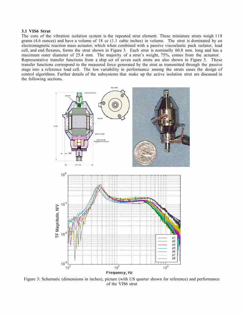
3.1 VIS6 StrutThe core of the vibration isolation system is the repeated strut element. These miniature struts weigh 118grams (4.6 ounces) and have a volume of 18 cc (1.1 cubic inches) in volume. The strut is dominated by anelectromagnetic reaction mass actuator, which when combined with a passive viscoelastic puck isolator, loadcell, and end flexures, forms the strut shown in Figure 3. Each strut is nominally 60.8 mm. long and has amaximum outer diameter of 25.4 mm. The majority of a strut’s weight, 75%, comes from the actuator. Representative transfer functions from a ship set of seven such struts are also shown in Figure 3. Thesetransfer functions correspond to the measured force generated by the strut as transmitted through the passivestage into a reference load cell. The low variability in performance among the struts eases the design ofcontrol algorithms. Further details of the subsystems that make up the active isolation strut are discussed inthe following sections.
2.393
axial end flexure
actuator
passive stage
Ø 1.010
spacers
.080
top view
load cell withintegrated end flexure
Figure 3: Schematic (dimensions in inches), picture (with US quarter shown for reference) and performanceof the VIS6 strut
3.1.1 VIS6 Actuator
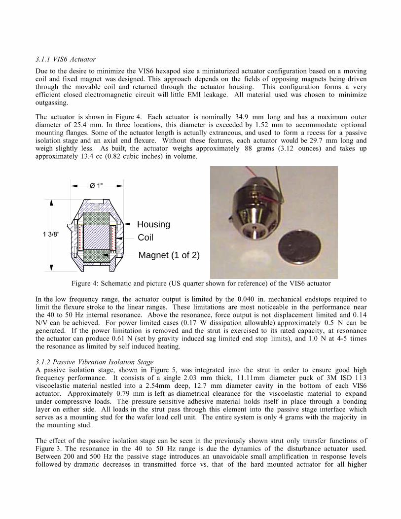
Due to the desire to minimize the VIS6 hexapod size a miniaturized actuator configuration based on a movingcoil and fixed magnet was designed. This approach depends on the fields of opposing magnets being driventhrough the movable coil and returned through the actuator housing. This configuration forms a veryefficient closed electromagnetic circuit will little EMI leakage. All material used was chosen to minimizeoutgassing.
The actuator is shown in Figure 4. Each actuator is nominally 34.9 mm long and has a maximum outerdiameter of 25.4 mm. In three locations, this diameter is exceeded by 1.52 mm to accommodate optionalmounting flanges. Some of the actuator length is actually extraneous, and used to form a recess for a passiveisolation stage and an axial end flexure. Without these features, each actuator would be 29.7 mm long andweigh slightly less. As built, the actuator weighs approximately 88 grams (3.12 ounces) and takes upapproximately 13.4 cc (0.82 cubic inches) in volume.
1 3/8"
Ø 1"
Coil
Magnet (1 of 2)
Housing
Figure 4: Schematic and picture (US quarter shown for reference) of the VIS6 actuator
In the low frequency range, the actuator output is limited by the 0.040 in. mechanical endstops required t olimit the flexure stroke to the linear ranges. These limitations are most noticeable in the performance nearthe 40 to 50 Hz internal resonance. Above the resonance, force output is not displacement limited and 0.14N/V can be achieved. For power limited cases (0.17 W dissipation allowable) approximately 0.5 N can begenerated. If the power limitation is removed and the strut is exercised to its rated capacity, at resonancethe actuator can produce 0.61 N (set by gravity induced sag limited end stop limits), and 1.0 N at 4-5 timesthe resonance as limited by self induced heating.
3.1.2 Passive Vibration Isolation StageA passive isolation stage, shown in Figure 5, was integrated into the strut in order to ensure good highfrequency performance. It consists of a single 2.03 mm thick, 11.11mm diameter puck of 3M ISD 113viscoelastic material nestled into a 2.54mm deep, 12.7 mm diameter cavity in the bottom of each VIS6actuator. Approximately 0.79 mm is left as diametrical clearance for the viscoelastic material to expandunder compressive loads. The pressure sensitive adhesive material holds itself in place through a bondinglayer on either side. All loads in the strut pass through this element into the passive stage interface whichserves as a mounting stud for the wafer load cell unit. The entire system is only 4 grams with the majority inthe mounting stud.
The effect of the passive isolation stage can be seen in the previously shown strut only transfer functions ofFigure 3. The resonance in the 40 to 50 Hz range is due the dynamics of the disturbance actuator used.Between 200 and 500 Hz the passive stage introduces an unavoidable small amplification in response levelsfollowed by dramatic decreases in transmitted force vs. that of the hard mounted actuator for all higher
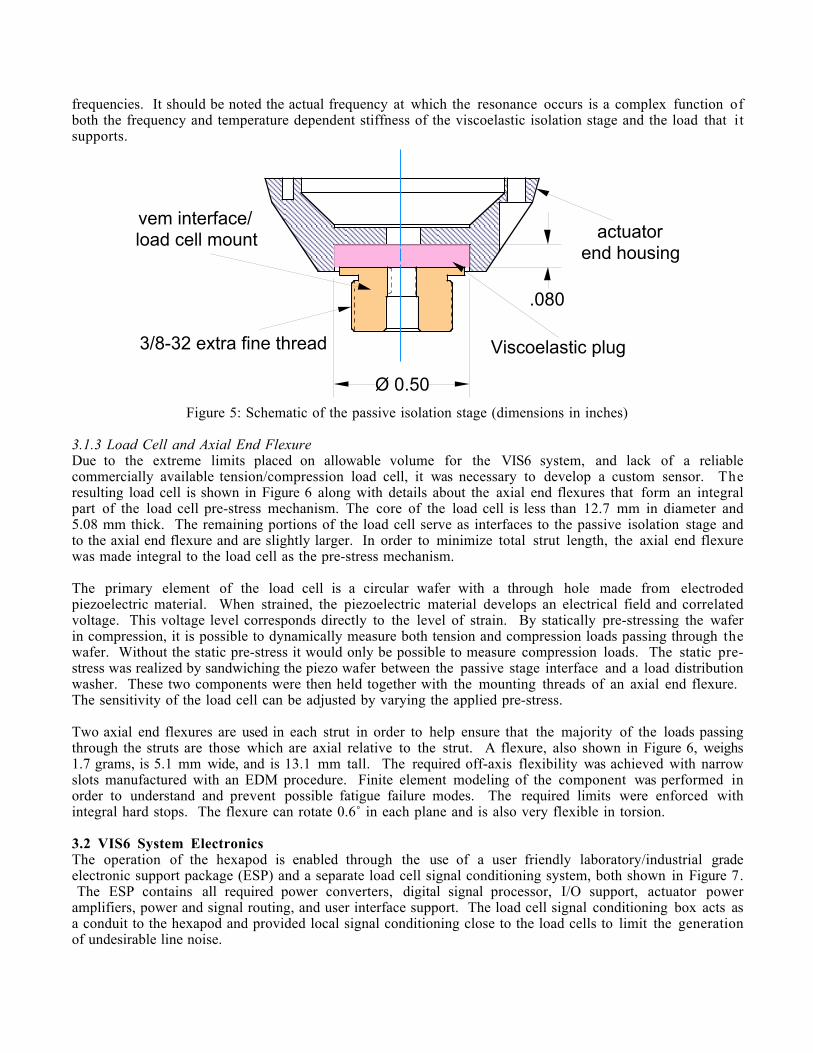
frequencies. It should be noted the actual frequency at which the resonance occurs is a complex function ofboth the frequency and temperature dependent stiffness of the viscoelastic isolation stage and the load that itsupports.
Viscoelastic plug
vem interface/load cell mount
3/8-32 extra fine thread
.080
Ø 0.50
actuatorend housing
Figure 5: Schematic of the passive isolation stage (dimensions in inches)
3.1.3 Load Cell and Axial End FlexureDue to the extreme limits placed on allowable volume for the VIS6 system, and lack of a reliablecommercially available tension/compression load cell, it was necessary to develop a custom sensor. Theresulting load cell is shown in Figure 6 along with details about the axial end flexures that form an integralpart of the load cell pre-stress mechanism. The core of the load cell is less than 12.7 mm in diameter and5.08 mm thick. The remaining portions of the load cell serve as interfaces to the passive isolation stage andto the axial end flexure and are slightly larger. In order to minimize total strut length, the axial end flexurewas made integral to the load cell as the pre-stress mechanism.
The primary element of the load cell is a circular wafer with a through hole made from electrodedpiezoelectric material. When strained, the piezoelectric material develops an electrical field and correlatedvoltage. This voltage level corresponds directly to the level of strain. By statically pre-stressing the waferin compression, it is possible to dynamically measure both tension and compression loads passing through thewafer. Without the static pre-stress it would only be possible to measure compression loads. The static pre-stress was realized by sandwiching the piezo wafer between the passive stage interface and a load distributionwasher. These two components were then held together with the mounting threads of an axial end flexure. The sensitivity of the load cell can be adjusted by varying the applied pre-stress.
Two axial end flexures are used in each strut in order to help ensure that the majority of the loads passingthrough the struts are those which are axial relative to the strut. A flexure, also shown in Figure 6, weighs1.7 grams, is 5.1 mm wide, and is 13.1 mm tall. The required off-axis flexibility was achieved with narrowslots manufactured with an EDM procedure. Finite element modeling of the component was performed inorder to understand and prevent possible fatigue failure modes. The required limits were enforced withintegral hard stops. The flexure can rotate 0.6˚ in each plane and is also very flexible in torsion.
3.2 VIS6 System ElectronicsThe operation of the hexapod is enabled through the use of a user friendly laboratory/industrial gradeelectronic support package (ESP) and a separate load cell signal conditioning system, both shown in Figure 7. The ESP contains all required power converters, digital signal processor, I/O support, actuator poweramplifiers, power and signal routing, and user interface support. The load cell signal conditioning box acts asa conduit to the hexapod and provided local signal conditioning close to the load cells to limit the generationof undesirable line noise.
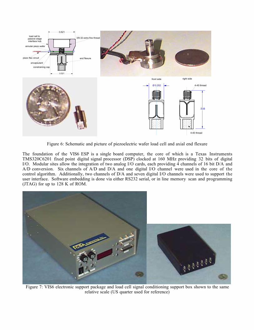
annular piezo wafer
constraining cap
end flexure
0.621
load cell topassive stageinterface hub
encapsulant
piezo flex circuit
0.521
3/8-32 extra fine thread
.516
Ø 0.202
front side right side
4-40 thread
4-40 thread
Figure 6: Schematic and picture of piezoelectric wafer load cell and axial end flexure
The foundation of the VIS6 ESP is a single board computer, the core of which is a Texas InstrumentsTMS320C6201 fixed point digital signal processor (DSP) clocked at 160 MHz providing 32 bits of digitalI/O. Modular sites allow the integration of two analog I/O cards, each providing 4 channels of 16 bit D/A andA/D conversion. Six channels of A/D and D/A and one digital I/O channel were used in the core of thecontrol algorithm. Additionally, two channels of D/A and seven digital I/O channels were used to support theuser interface. Software embedding is done via either RS232 serial, or in line memory scan and programming(JTAG) for up to 128 K of ROM.
Figure 7: VIS6 electronic support package and load cell signal conditioning support box shown to the samerelative scale (US quarter used for reference)
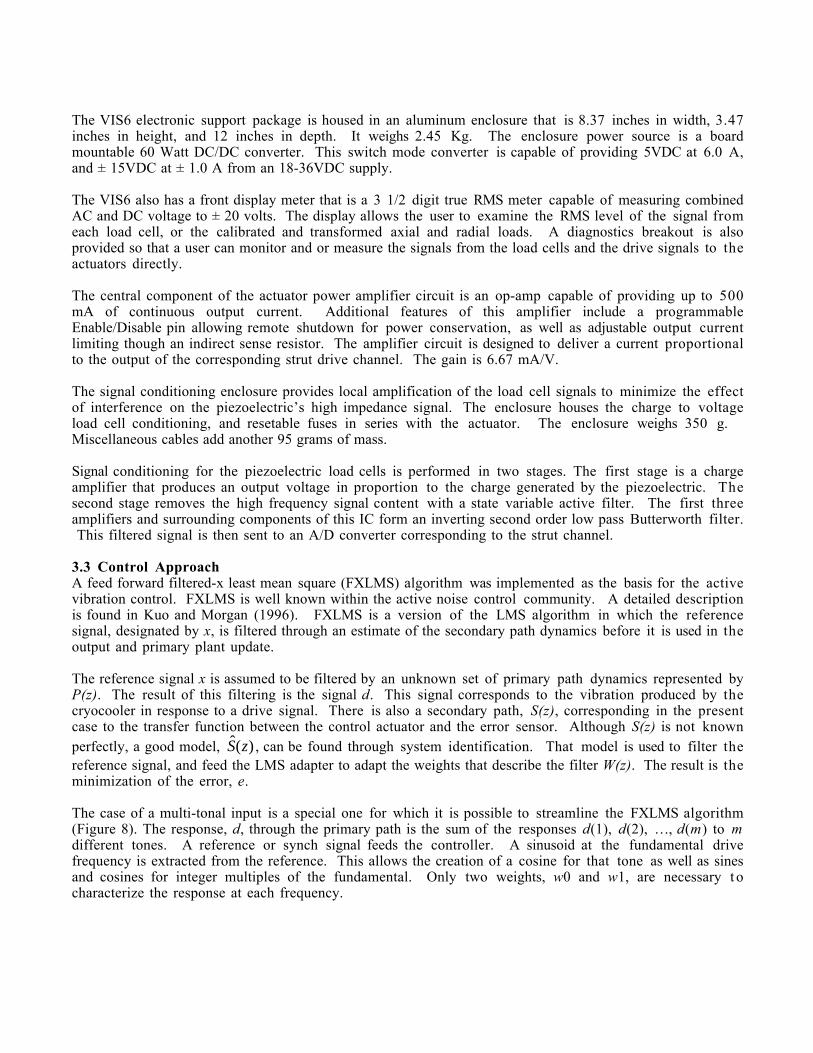
The VIS6 electronic support package is housed in an aluminum enclosure that is 8.37 inches in width, 3.47inches in height, and 12 inches in depth. It weighs 2.45 Kg. The enclosure power source is a boardmountable 60 Watt DC/DC converter. This switch mode converter is capable of providing 5VDC at 6.0 A,and ± 15VDC at ± 1.0 A from an 18-36VDC supply.
The VIS6 also has a front display meter that is a 3 1/2 digit true RMS meter capable of measuring combinedAC and DC voltage to ± 20 volts. The display allows the user to examine the RMS level of the signal fromeach load cell, or the calibrated and transformed axial and radial loads. A diagnostics breakout is alsoprovided so that a user can monitor and or measure the signals from the load cells and the drive signals to theactuators directly.
The central component of the actuator power amplifier circuit is an op-amp capable of providing up to 500mA of continuous output current. Additional features of this amplifier include a programmableEnable/Disable pin allowing remote shutdown for power conservation, as well as adjustable output currentlimiting though an indirect sense resistor. The amplifier circuit is designed to deliver a current proportionalto the output of the corresponding strut drive channel. The gain is 6.67 mA/V.
The signal conditioning enclosure provides local amplification of the load cell signals to minimize the effectof interference on the piezoelectric’s high impedance signal. The enclosure houses the charge to voltageload cell conditioning, and resetable fuses in series with the actuator. The enclosure weighs 350 g. Miscellaneous cables add another 95 grams of mass.
Signal conditioning for the piezoelectric load cells is performed in two stages. The first stage is a chargeamplifier that produces an output voltage in proportion to the charge generated by the piezoelectric. Thesecond stage removes the high frequency signal content with a state variable active filter. The first threeamplifiers and surrounding components of this IC form an inverting second order low pass Butterworth filter. This filtered signal is then sent to an A/D converter corresponding to the strut channel.
3.3 Control ApproachA feed forward filtered-x least mean square (FXLMS) algorithm was implemented as the basis for the activevibration control. FXLMS is well known within the active noise control community. A detailed descriptionis found in Kuo and Morgan (1996). FXLMS is a version of the LMS algorithm in which the referencesignal, designated by x, is filtered through an estimate of the secondary path dynamics before it is used in theoutput and primary plant update.
The reference signal x is assumed to be filtered by an unknown set of primary path dynamics represented byP(z). The result of this filtering is the signal d. This signal corresponds to the vibration produced by thecryocooler in response to a drive signal. There is also a secondary path, S(z), corresponding in the presentcase to the transfer function between the control actuator and the error sensor. Although S(z) is not knownperfectly, a good model, ˆ( )S z , can be found through system identification. That model is used to filter thereference signal, and feed the LMS adapter to adapt the weights that describe the filter W(z). The result is theminimization of the error, e.
The case of a multi-tonal input is a special one for which it is possible to streamline the FXLMS algorithm(Figure 8). The response, d, through the primary path is the sum of the responses d(1), d(2), …, d(m) to mdifferent tones. A reference or synch signal feeds the controller. A sinusoid at the fundamental drivefrequency is extracted from the reference. This allows the creation of a cosine for that tone as well as sinesand cosines for integer multiples of the fundamental. Only two weights, w0 and w1, are necessary t ocharacterize the response at each frequency.
d(1)
e(1)
y(1)
Ref./Synch
Sine wavegenerator(tone 1)
P(1)
90 deg.phase shift
LMSx'(1)
S(1)
w0(1)
w1(1)
cosine(1)
sine(1)
Σ+
+
S(1)^
+
-
Σ
+Σ
e
e(2) e(3)
sine and cosine wavesfor m other tones
x(1)
error to m othertone controllers
e(m)
Figure 8: Specialized multi-tonal format of the FXLMS algorithm
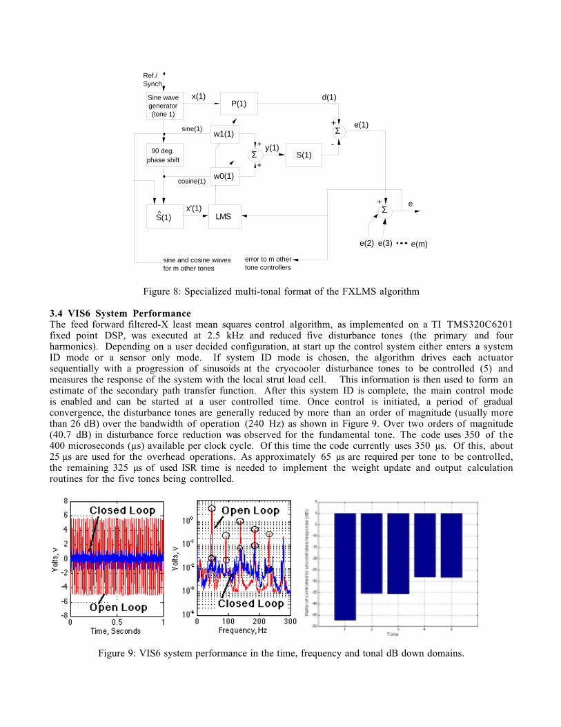
3.4 VIS6 System PerformanceThe feed forward filtered-X least mean squares control algorithm, as implemented on a TI TMS320C6201fixed point DSP, was executed at 2.5 kHz and reduced five disturbance tones (the primary and fourharmonics). Depending on a user decided configuration, at start up the control system either enters a systemID mode or a sensor only mode. If system ID mode is chosen, the algorithm drives each actuatorsequentially with a progression of sinusoids at the cryocooler disturbance tones to be controlled (5) andmeasures the response of the system with the local strut load cell. This information is then used to form anestimate of the secondary path transfer function. After this system ID is complete, the main control modeis enabled and can be started at a user controlled time. Once control is initiated, a period of gradualconvergence, the disturbance tones are generally reduced by more than an order of magnitude (usually morethan 26 dB) over the bandwidth of operation (240 Hz) as shown in Figure 9. Over two orders of magnitude(40.7 dB) in disturbance force reduction was observed for the fundamental tone. The code uses 350 of the400 microseconds (µs) available per clock cycle. Of this time the code currently uses 350 µs. Of this, about25 µs are used for the overhead operations. As approximately 65 µs are required per tone to be controlled,the remaining 325 µs of used ISR time is needed to implement the weight update and output calculationroutines for the five tones being controlled.
Figure 9: VIS6 system performance in the time, frequency and tonal dB down domains.
4. VRS1
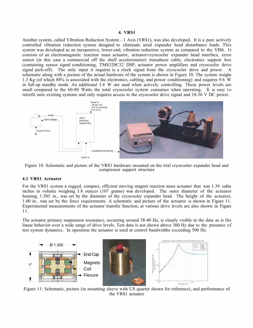
Another system, called Vibration Reduction System - 1 Axis (VRS1), was also developed. It is a pure activelycontrolled vibration reduction system designed to eliminate axial expander head disturbance loads. Thissystem was developed as an inexpensive, lower-end, vibration reduction system as compared to the VIS6. I tconsists of an electromagnetic reaction mass actuator, actuator/cryocooler expander head interface, errorsensor (in this case a commercial off the shelf accelerometer) transducer cable, electronics support box(containing sensor signal conditioning, TMS320C32 DSP, actuator power amplifiers and cryocooler drivesignal pick-off). The only input it requires is a clock signal from the cryocooler drive and power. Aschematic along with a picture of the actual hardware of the system is shown in Figure 10. The system weighs1.3 Kg (of which 88% is associated with the electronics, cabling, and power conditioning) and requires 9.6 Win full-up standby mode. An additional 3.4 W are used when actively controlling. These power levels aresmall compared to the 60-80 Watts the total cryocooler system consumes when operating. It is easy t oretrofit onto existing systems and only requires access to the cryocooler drive signal and 18-36 V DC power.
Power In 18-36 V DC 24V DC Nominal 9.6-13 W
Accel
Drive Voltage
Counter Force
Synch In
Conditioned Accel Out
VRS1ElectronicSupport Box
Figure 10: Schematic and picture of the VRS1 hardware mounted on the trial cryocooler expander head andcompressor support structure
4.1 VRS1 Actuator
For the VRS1 system a rugged, compact, efficient moving magnet reaction mass actuator that was 1.39 cubicinches in volume weighing 3.8 ounces (107 grams) was developed. The outer diameter of the actuatorhousing, 1.305 in., was set by the diameter of the cryocooler expander head. The height of the actuator,1.00 in., was set by the force requirements. A schematic and picture of the actuator is shown in Figure 11.Experimental measurements of the actuator transfer function, at various drive levels are also shown in Figure11.
The actuator primary suspension resonance, occurring around 38-40 Hz, is clearly visible in the data as is thelinear behavior over a wide range of drive levels. Test data is not shown above 300 Hz due to the presence oftest system dynamics. In operation the actuator is used at control bandwidths exceeding 500 Hz.
1"
Ø 1.305
MagnetsCoil
End Cap
Flexure
Figure 11: Schematic, picture (in mounting sleeve with US quarter shown for reference), and performance of
the VRS1 actuator
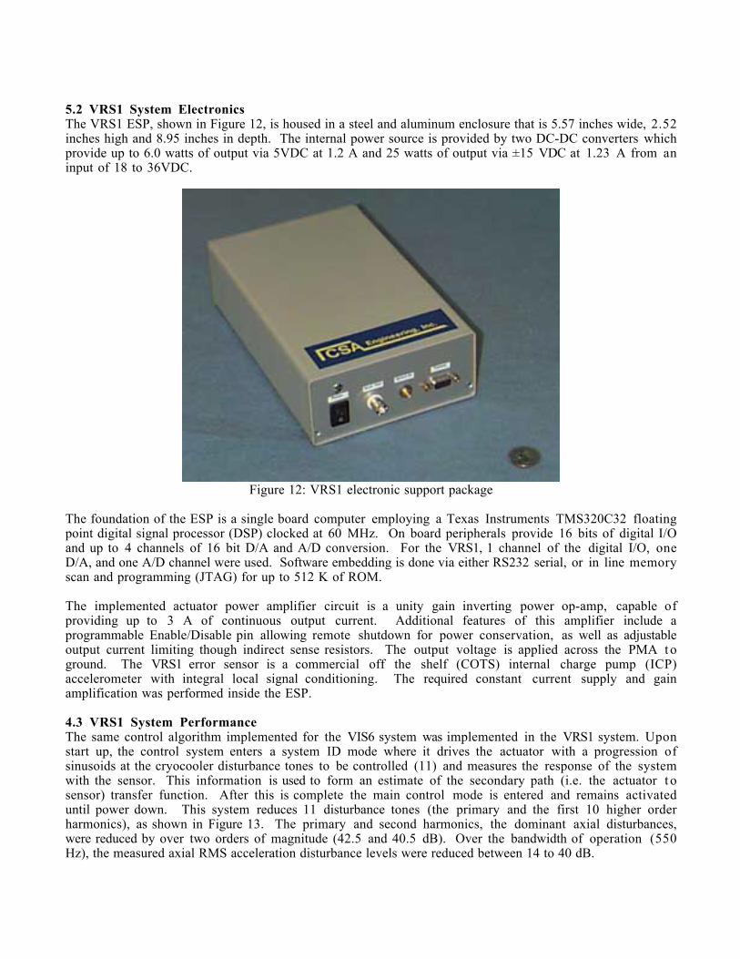
5.2 VRS1 System ElectronicsThe VRS1 ESP, shown in Figure 12, is housed in a steel and aluminum enclosure that is 5.57 inches wide, 2.52inches high and 8.95 inches in depth. The internal power source is provided by two DC-DC converters whichprovide up to 6.0 watts of output via 5VDC at 1.2 A and 25 watts of output via ±15 VDC at 1.23 A from aninput of 18 to 36VDC.
Figure 12: VRS1 electronic support package
The foundation of the ESP is a single board computer employing a Texas Instruments TMS320C32 floatingpoint digital signal processor (DSP) clocked at 60 MHz. On board peripherals provide 16 bits of digital I/Oand up to 4 channels of 16 bit D/A and A/D conversion. For the VRS1, 1 channel of the digital I/O, oneD/A, and one A/D channel were used. Software embedding is done via either RS232 serial, or in line memoryscan and programming (JTAG) for up to 512 K of ROM.
The implemented actuator power amplifier circuit is a unity gain inverting power op-amp, capable ofproviding up to 3 A of continuous output current. Additional features of this amplifier include aprogrammable Enable/Disable pin allowing remote shutdown for power conservation, as well as adjustableoutput current limiting though indirect sense resistors. The output voltage is applied across the PMA t oground. The VRS1 error sensor is a commercial off the shelf (COTS) internal charge pump (ICP)accelerometer with integral local signal conditioning. The required constant current supply and gainamplification was performed inside the ESP.
4.3 VRS1 System PerformanceThe same control algorithm implemented for the VIS6 system was implemented in the VRS1 system. Uponstart up, the control system enters a system ID mode where it drives the actuator with a progression ofsinusoids at the cryocooler disturbance tones to be controlled (11) and measures the response of the systemwith the sensor. This information is used to form an estimate of the secondary path (i.e. the actuator t osensor) transfer function. After this is complete the main control mode is entered and remains activateduntil power down. This system reduces 11 disturbance tones (the primary and the first 10 higher orderharmonics), as shown in Figure 13. The primary and second harmonics, the dominant axial disturbances,were reduced by over two orders of magnitude (42.5 and 40.5 dB). Over the bandwidth of operation (550Hz), the measured axial RMS acceleration disturbance levels were reduced between 14 to 40 dB.
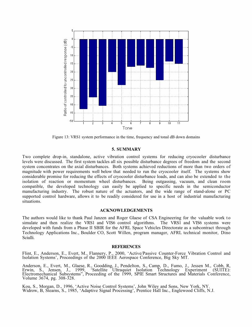
Figure 13: VRS1 system performance in the time, frequency and tonal dB down domains
5. SUMMARY
Two complete drop-in, standalone, active vibration control systems for reducing cryocooler disturbancelevels were discussed. The first system tackles all six possible disturbance degrees of freedom and the secondsystem concentrates on the axial disturbances. Both systems achieved reductions of more than two orders ofmagnitude with power requirements well below that needed to run the cryocooler itself. The systems showconsiderable promise for reducing the effects of cryocooler disturbance loads, and can also be extended to theisolation of reaction or momentum wheel disturbances. Being outgassing, vacuum, and clean roomcompatible, the developed technology can easily be applied to specific needs in the semiconductormanufacturing industry. The robust nature of the actuators, and the wide range of stand-alone or PCsupported control hardware, allows it to be readily considered for use in a host of industrial manufacturingsituations.
ACKNOWLEDGEMENTS
The authors would like to thank Paul Janzen and Roger Glaese of CSA Engineering for the valuable work t osimulate and then realize the VRS1 and VIS6 control algorithms. The VRS1 and VIS6 systems weredeveloped with funds from a Phase II SBIR for the AFRL Space Vehicles Directorate as a subcontract throughTechnology Applications Inc., Boulder CO, Scott Willen, program manager, AFRL technical monitor, DinoSciulli.
REFERENCES
Flint, E., Anderson, E., Evert, M., Flannery, P., 2000, ‘Active/Passive Counter-Force Vibration Control andIsolation Systems’, Proceedings of the 2000 IEEE Aerospace Conference, Big Sky MT.
Anderson, E., Evert, M., Glaese, R., Goodding, J., Pendelton, S., Camp, D., Fumo, J., Jessen M., Cobb, R,Erwin, S., Jensen, J., 1999, ‘Satellite Ultraquiet Isolation Technology Experiment (SUITE):Electromechanical Subsystems”, Proceeding of the 1999, SPIE Smart Structures and Materials Conference,Volume 3674, pg. 308-328.
Kou, S., Morgan, D., 1996, ‘Active Noise Control Systems’, John Wiley and Sons, New York, NY.Widrow, B, Stearns, S., 1985, ‘Adaptive Signal Processing’, Prentice Hall Inc., Englewood Cliffs, N.J.