Embed Size (px)
Citation preview
Cryo-Torr® PumpInstallation, Operation and
Maintenance Manual
8040613 Revision AA
Cryo-Torr® Pump Installation, Operation and Maintenance Instructions
Brooks Automation8040613 Revision AA
Information provided within this document is subject to change without notice, and although believed to be accurate, Brooks Automation assumes no responsibility for any errors, omissions, or inaccuracies.
AcuLigner™, Align™, AquaTran™, AutoTeach™, ATR™, AXM™, Basic Blue™, BiSymmetrik™, CenterSmart™, Cool Solutions™, Crate to Operate™, e-RMA™, e-Spares™, e-Volution™, FastRegen™, FIXLOAD™, FrogLeg™, InLigner™, InCooler™, Interface™, Jet Engine™, LowProfile™, M2 Nano™, Mini-Ion™, PASIV™, PowerPak™, PerformanceBlue™, PowerPak™, PowerTools™, QuadraFly™, Radius™, Radient™, Radient Express™, Reliance™, Reliance ATR™, RetroEase™, SCARA™, SmartPM™, SPOTLevel™, Synetics™, The New Pathway to Productivity™, Time Optimized Trajectory™, Time Optimal Trajectory™, Time Optimized Path™, TopCooler™, TopLigner™, Ultimate Blue™, VAC-407™, VacuTran™, Vacuum Quality Monitor™, VQM™, Vacuum Quality Index™, VQI™, and the Brooks logo are trademarks of Brooks Automation, Inc. AcuTran®, AquaTrap®, Conductron®, Convectron®, the Cool Solutions logo, Cryodyne®, Cryotiger®, Cryo-Torr®, Fusion®, GOLDLink®, Granville-Phillips®, Guardian®, GUTS®, Helix®, Jet®, Leapfrog®, MagnaTran®, MapTrak®, Marathon®, Marathon 2®, Marathon Express®, Micro-Ion®, MiniConvectron®, On-Board®, Polycold®, Razor®, Simplicity Solutions®, the Simplicity Solutions logo, Stabil-Ion®, TrueBlue®, TurboPlus®, Vision®, Zaris®, and the Brooks Automation logo are registered U.S. trademarks of Brooks Automation, Inc. All other trademarks are properties of their respective owners.
© 2013 Brooks Automation, Inc. All Rights Reserved. The information included in this manual is Proprietary Information of Brooks Automation and is provided for the use of Brooks Automation customers only and cannot be used for distribution, reproduction, or sale without the express written permission of Brooks Automation. This information may be incorporated into the user’s documentation, however any changes made by the user to this information is the responsibility of the user.
For Technical Support:
Visit us online: www.brooks.com
January 14, 2013 Part Num 8040613 Revision AA
This technology is subject to United States export Administration Regulations and authorized to the destination only; diversion contrary to U.S. law is prohibited.
Printed in the U.S.A.
Location GUTS® Contact Number
North America+1-800-FOR-GUTS (1-800-367-4887)+1-978-262-2900
Europe +49-1804-CALL-GUTS (+49-1804-2255-4887)
Japan +81-45-477-5980
China +86-21-5131-7066
Taiwan +886-3-5525225
Korea +82-31-288-2500
Singapore +65-6464-1481
©2013 Brooks Automation Inc. Pub. No. 8040613, Rev. AA, 01/14/2013 ECO No. 63723 1-i
Cryo-Torr® Pump Installation, Operation and Maintenance Instructions
Table of Contents
Figures
Tables
Safety Conventions
Section 1 - Cryo-Torr Cryopump DescriptionIntroduction . . . . . . . . . . . . . . . . . . . . . . . . . . . . . . . . . . . . . . . . . . . . . . . . . . . . . . . 1-1Installation, Operation, and Service Instructions . . . . . . . . . . . . . . . . . . . . . . . . . . . 1-1Specifications . . . . . . . . . . . . . . . . . . . . . . . . . . . . . . . . . . . . . . . . . . . . . . . . . . . . . . 1-4Theory of Operation . . . . . . . . . . . . . . . . . . . . . . . . . . . . . . . . . . . . . . . . . . . . . . . . 1-15
Cold Head . . . . . . . . . . . . . . . . . . . . . . . . . . . . . . . . . . . . . . . . . . . . . . . . . . . . 1-15Vacuum Vessel and Arrays . . . . . . . . . . . . . . . . . . . . . . . . . . . . . . . . . . . . . . . 1-15Compressor Gas and Oil Flows . . . . . . . . . . . . . . . . . . . . . . . . . . . . . . . . . . . . 1-17Cryo-Torr Interface . . . . . . . . . . . . . . . . . . . . . . . . . . . . . . . . . . . . . . . . . . . . . 1-17
Section 2 - InstallationIntroduction . . . . . . . . . . . . . . . . . . . . . . . . . . . . . . . . . . . . . . . . . . . . . . . . . . . . . . . 2-1Installation . . . . . . . . . . . . . . . . . . . . . . . . . . . . . . . . . . . . . . . . . . . . . . . . . . . . . . . . 2-2
Vent Pipe Connection . . . . . . . . . . . . . . . . . . . . . . . . . . . . . . . . . . . . . . . . . . . . 2-2Roughing Pump Connection . . . . . . . . . . . . . . . . . . . . . . . . . . . . . . . . . . . . . . . . . . 2-2Purge Gas Connection . . . . . . . . . . . . . . . . . . . . . . . . . . . . . . . . . . . . . . . . . . . . . . . 2-3Helium Return and Supply Line Connections . . . . . . . . . . . . . . . . . . . . . . . . . . . . . 2-5Power Cable Connection . . . . . . . . . . . . . . . . . . . . . . . . . . . . . . . . . . . . . . . . . . . . . 2-5Crossover Pressure Calculations . . . . . . . . . . . . . . . . . . . . . . . . . . . . . . . . . . . . . . . 2-5
Optimizing Crossover Pressure . . . . . . . . . . . . . . . . . . . . . . . . . . . . . . . . . . . . . 2-6Cryo-Torr Cryopump Capacity Calculations . . . . . . . . . . . . . . . . . . . . . . . . . . . . . . 2-7Crossover Cycle Calculations . . . . . . . . . . . . . . . . . . . . . . . . . . . . . . . . . . . . . . . . . 2-8Cryopump Start-up Procedure . . . . . . . . . . . . . . . . . . . . . . . . . . . . . . . . . . . . . . . . . 2-8Cryopump Shutdown Procedure . . . . . . . . . . . . . . . . . . . . . . . . . . . . . . . . . . . . . . . 2-9Cryopump Storage . . . . . . . . . . . . . . . . . . . . . . . . . . . . . . . . . . . . . . . . . . . . . . . . . 2-10
Section 3 - RegenerationIntroduction . . . . . . . . . . . . . . . . . . . . . . . . . . . . . . . . . . . . . . . . . . . . . . . . . . . . . . . 3-1When to Regenerate . . . . . . . . . . . . . . . . . . . . . . . . . . . . . . . . . . . . . . . . . . . . . . . . . 3-1Assisted Regeneration . . . . . . . . . . . . . . . . . . . . . . . . . . . . . . . . . . . . . . . . . . . . . . . 3-2
Section 4 - Troubleshooting
©2013 Brooks Automation Inc. Pub. No. 8040613, Rev. AA, 01/14/2013 ECO No. 63723 1-ii
Cryo-Torr® Pump Installation, Operation and Maintenance Instructions
Troubleshooting the Cryopump . . . . . . . . . . . . . . . . . . . . . . . . . . . . . . . . . . . . . . . . 4-1Technical Inquiries . . . . . . . . . . . . . . . . . . . . . . . . . . . . . . . . . . . . . . . . . . . . . . . . . 4-1
Section 5 - Maintenance ProceduresHelium Circuit Decontamination . . . . . . . . . . . . . . . . . . . . . . . . . . . . . . . . . . . . . . . 5-1Cryo-Torr Cryopump Decontamination Procedures . . . . . . . . . . . . . . . . . . . . . . . . 5-1Cleaning the Cryo-Torr Cryopump . . . . . . . . . . . . . . . . . . . . . . . . . . . . . . . . . . . . . 5-3
Appendix A - Customer Brooks Automation Technical Support Information
Index
©2013 Brooks Automation Inc. Pub. No. 8040613, Rev. AA, 01/14/2013 ECO No. 63723 2-iii
Cryo-Torr® Pump Installation, Operation and Maintenance Instructions
Figures
Figure 1-1: Cryo-Torr Pumps . . . . . . . . . . . . . . . . . . . . . . . . . . . . . . . . . . . . . . . . . . . . . . . . . . . 1-2Figure 1-2: Cryo-Torr Pumps . . . . . . . . . . . . . . . . . . . . . . . . . . . . . . . . . . . . . . . . . . . . . . . . . . . 1-3Figure 1-3: Cutaway View of a Typical Cryo-Torr Pump . . . . . . . . . . . . . . . . . . . . . . . . . . . . 1-16Figure 1-4: Cryo-Torr Interface . . . . . . . . . . . . . . . . . . . . . . . . . . . . . . . . . . . . . . . . . . . . . . . . 1-17Figure 1-5: Typical Cryo-Torr System with 9000 Series Compressor . . . . . . . . . . . . . . . . . . . 1-18Figure 1-6: Typical Cryo-Torr System with 8200 Compressor . . . . . . . . . . . . . . . . . . . . . . . . 1-19Figure 1-7: Typical Cryo-Torr System with 8600 Compressor . . . . . . . . . . . . . . . . . . . . . . . . 1-20Figure 2-1: Block Diagram for Cryo-Torr System Installation . . . . . . . . . . . . . . . . . . . . . . . . . 2-1Figure 2-2: Gas/Electrical Components on a Typical Cryo-Torr Cryopump . . . . . . . . . . . . . . . 2-4

This Page Intentionally Left Blank
©2013 Brooks Automation Inc. Pub. No. 8040613, Rev. AA, 01/14/2013 ECO No. 63723 3-v
Cryo-Torr® Pump Installation, Operation and Maintenance Instructions
Tables
Table 1-1: Cryo-Torr 4F Cryopump Specifications .................................................................. 1-4Table 1-2: Cryo-Torr 8 Cryopump Specifications ..................................................................... 1-5Table 1-3: Cryo-Torr 8F Cryopump Specifications .................................................................. 1-6Table 1-4: Cryo-Torr 10 Cryopump Specifications ................................................................... 1-7Table 1-5: Cryo-Torr 10F Cryopump Specifications ................................................................ 1-8Table 1-6: Cryo-Torr 250F Standard Cryopump Specifications ............................................... 1-9Table 1-7: Cryo-Torr 250FH High Capacity Cryopump Specifications ................................. 1-10Table 1-8: Cryo-Torr 400 Standard Capacity Cryopump Specifications ................................ 1-11Table 1-9: Cryo-Torr 400 High Capacity Cryopump Specifications ...................................... 1-12Table 1-10: Cryo-Torr 500 Cryopump Specifications ............................................................. 1-13Table 1-11: Cryo-Torr 20HP Cryopump Specifications .......................................................... 1-14Table 2-1: Crossover Values ...................................................................................................... 2-6Table 2-2: Condensable Gases Capacity (Argon, Nitrogen, Oxygen, etc.) ............................... 2-7Table 3-1: Required Accessories for Assisted Regeneration ..................................................... 3-2Table 4-1: Troubleshooting Procedures ..................................................................................... 4-2Table 5-1: Indium Gasket Screw Torque Specifications ........................................................... 5-4

This Page Intentionally Left Blank
Document Title
©2013 Brooks Automation Inc. Pub. No. 8040636, Rev. AA, 01/14/2013 ECO No. 63723 S-1
Safety Conventions
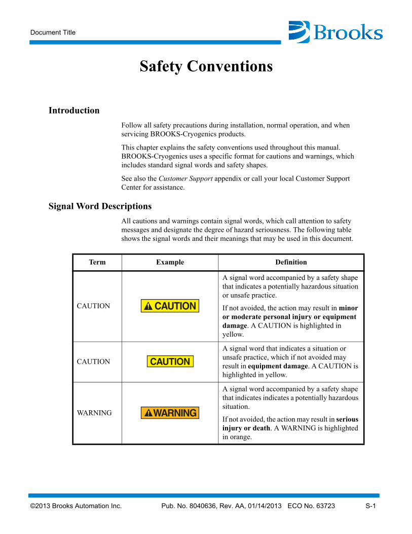
Introduction
Follow all safety precautions during installation, normal operation, and when servicing BROOKS-Cryogenics products.
This chapter explains the safety conventions used throughout this manual. BROOKS-Cryogenics uses a specific format for cautions and warnings, which includes standard signal words and safety shapes.
See also the Customer Support appendix or call your local Customer Support Center for assistance.
Signal Word Descriptions
All cautions and warnings contain signal words, which call attention to safety messages and designate the degree of hazard seriousness. The following table shows the signal words and their meanings that may be used in this document.
Term Example Definition
CAUTION
A signal word accompanied by a safety shape that indicates a potentially hazardous situation or unsafe practice.
If not avoided, the action may result in minor or moderate personal injury or equipment damage. A CAUTION is highlighted in yellow.
CAUTION
A signal word that indicates a situation or unsafe practice, which if not avoided may result in equipment damage. A CAUTION is highlighted in yellow.
WARNING
A signal word accompanied by a safety shape that indicates indicates a potentially hazardous situation.
If not avoided, the action may result in serious injury or death. A WARNING is highlighted in orange.
Safety Conventions
S-2 ©2013 Brooks Automation Inc. Pub. No. 8040636, Rev. AA, 01/14/2013 ECO No. 63723
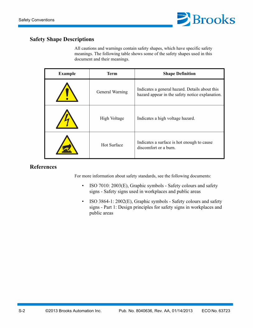
Safety Shape Descriptions
All cautions and warnings contain safety shapes, which have specific safety meanings. The following table shows some of the safety shapes used in this document and their meanings.
References
For more information about safety standards, see the following documents:
• ISO 7010: 2003(E), Graphic symbols - Safety colours and safety signs - Safety signs used in workplaces and public areas
• ISO 3864-1: 2002(E), Graphic symbols - Safety colours and safety signs - Part 1: Design principles for safety signs in workplaces and public areas
Example Term Shape Definition
General WarningIndicates a general hazard. Details about this hazard appear in the safety notice explanation.
High Voltage Indicates a high voltage hazard.
Hot SurfaceIndicates a surface is hot enough to cause discomfort or a burn.
©2013 Brooks Automation Inc. Pub. No. 8040613, Rev. AA, 01/14/2013 ECO No. 63723 1-1
Cryo-Torr® Pump Installation, Operation and Maintenance Instructions
Section 1 - Cryo-Torr Cryopump Description
Introduction
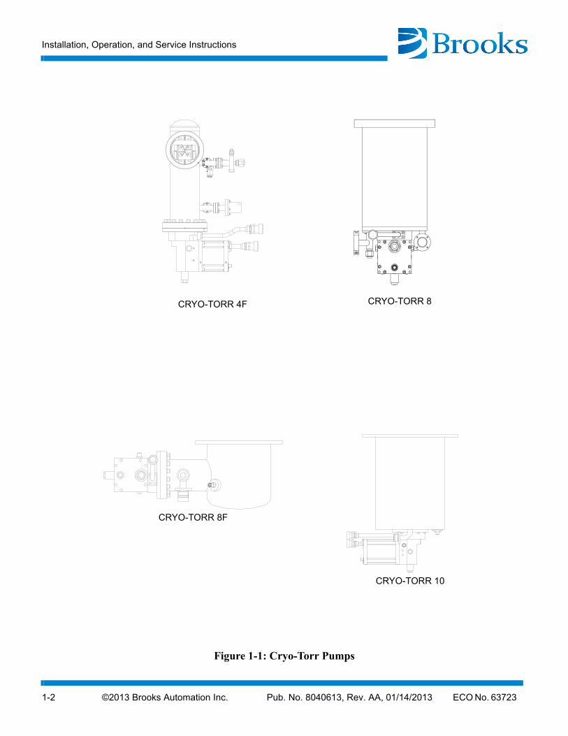
Cryo-Torr pumps, shown in Figure 1-1 and Figure 1-2, are one of the two major components that make up the Cryo-Torr Pumping System. The second component is the Compressor. Instructions for the compressor are contained in each compressor manual.
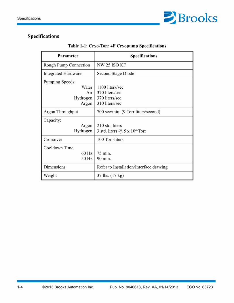
The Cryo-Torr Pump provides fast, clean pumping of all gases in the 10-3 to 10-9 Torr range. The cryopump operates on the principle that gases can be condensed and held at extremely low vapor pressures, achieving high speeds and throughputs, as described in Table 1-1 - Table 1-11.
Your Cryo-Torr Pump is a highly-reliable and rugged unit that requires a minimum of servicing. Since the cryopump exposes no moving parts, operating fluids, or backing pumps to the vacuum, the possibility of system or process contamination from the cryopump itself is eliminated.
Installation, Operation, and Service Instructions
Installation, Operation and Maintenance Instructions for your Cryo-Torr vacuum pump provides easily accessible information. All personnel with installation, operation, and servicing responsibilities should become familiar with the contents of these instructions to ensure safe, reliable cryopump performance.
Installation, Operation, and Service Instructions
1-2 ©2013 Brooks Automation Inc. Pub. No. 8040613, Rev. AA, 01/14/2013 ECO No. 63723
Figure 1-1:
CRYO-TORR 8
CRYO-TORR 8F
CRYO-TORR 4F
CRYO-TORR 10
Cryo-Torr Pumps
©2013 Brooks Automation Inc. Pub. No. 8040613, Rev. AA, 01/14/2013 ECO No. 63723 1-3
Cryo-Torr® Pump Installation, Operation and Maintenance Instructions
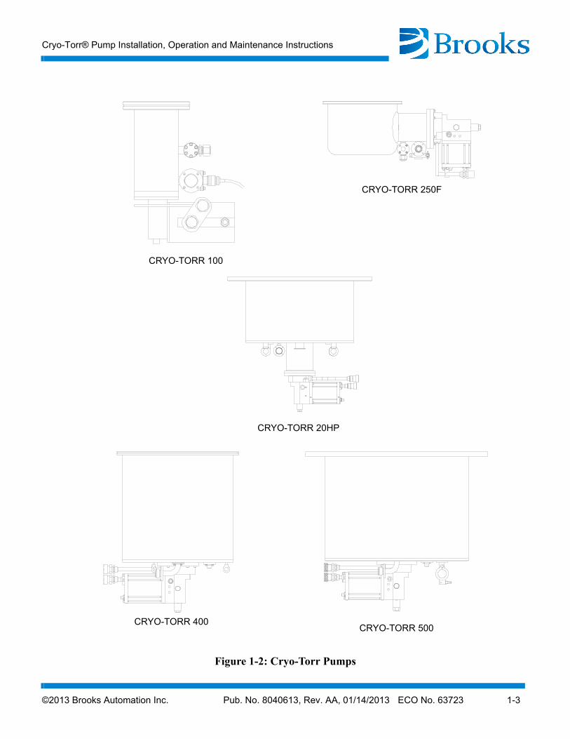
Figure 1-2:
CRYO-TORR 250F
CRYO-TORR 400
CRYO-TORR 100
CRYO-TORR 500
CRYO-TORR 20HP
Cryo-Torr Pumps
Specifications
1-4 ©2013 Brooks Automation Inc. Pub. No. 8040613, Rev. AA, 01/14/2013 ECO No. 63723
Specifications
Table 1-1: Cryo-Torr 4F Cryopump Specifications
Parameter Specifications
Rough Pump Connection NW 25 ISO KF
Integrated Hardware Second Stage Diode
Pumping Speeds:Water
AirHydrogen
Argon
1100 liters/sec370 liters/sec370 liters/sec310 liters/sec
Argon Throughput 700 scc/min. (9 Torr liters/second)
Capacity:Argon
Hydrogen210 std. liters3 std. liters @ 5 x 10⁻⁶ Torr
Crossover 100 Torr-liters
Cooldown Time 60 Hz 50 Hz
75 min.90 min.
Dimensions Refer to Installation/Interface drawing
Weight 37 lbs. (17 kg)
©2013 Brooks Automation Inc. Pub. No. 8040613, Rev. AA, 01/14/2013 ECO No. 63723 1-5
Cryo-Torr® Pump Installation, Operation and Maintenance Instructions
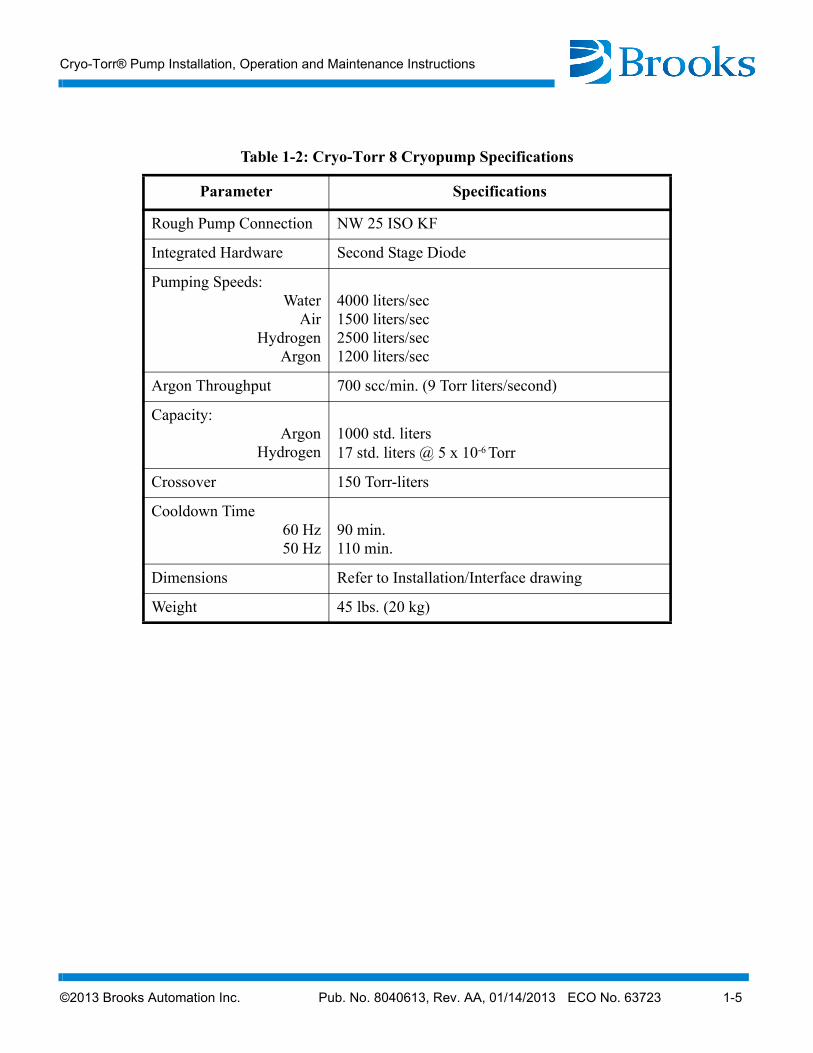
Table 1-2: Cryo-Torr 8 Cryopump Specifications
Parameter Specifications
Rough Pump Connection NW 25 ISO KF
Integrated Hardware Second Stage Diode
Pumping Speeds:Water
AirHydrogen
Argon
4000 liters/sec1500 liters/sec2500 liters/sec1200 liters/sec
Argon Throughput 700 scc/min. (9 Torr liters/second)
Capacity:Argon
Hydrogen1000 std. liters17 std. liters @ 5 x 10⁻⁶ Torr
Crossover 150 Torr-liters
Cooldown Time 60 Hz 50 Hz
90 min.110 min.
Dimensions Refer to Installation/Interface drawing
Weight 45 lbs. (20 kg)

Specifications
1-6 ©2013 Brooks Automation Inc. Pub. No. 8040613, Rev. AA, 01/14/2013 ECO No. 63723
Table 1-3: Cryo-Torr 8F Cryopump Specifications
Parameter Specifications
Rough Pump Connection NW 25 ISO KF
Integrated Hardware Second Stage Diode
Pumping Speeds:Water
AirHydrogen
Argon
4000 liters/sec1500 liters/sec2200 liters/sec1200 liters/sec
Argon Throughput 700 scc/min. (8.9 Torr liters/second)
Capacity:Argon
Hydrogen1000 std. liters8 std. liters @ 5 x 10⁻⁶ Torr
Crossover 150 Torr-liters
Cooldown Time 60 Hz 50 Hz
90 min.110 min.
Dimensions Refer to Installation/Interface drawing
Weight 42 lbs. (19 kg)

©2013 Brooks Automation Inc. Pub. No. 8040613, Rev. AA, 01/14/2013 ECO No. 63723 1-7
Cryo-Torr® Pump Installation, Operation and Maintenance Instructions
Table 1-4: Cryo-Torr 10 Cryopump Specifications
Parameter Specifications
Rough Pump Connection NW 25 ISO KF
Integrated Hardware Second Stage Diode
Pumping Speeds:Water
AirHydrogen
Argon
9000 liters/sec3000 liters/sec5000 liters/sec2500 liters/sec
Argon Throughput 1500 scc/min. (19 Torr liters/second)
Capacity:Argon
Hydrogen2000 std. liters24 std. liters @ 5 x 10⁻⁶ Torr
Crossover 300 Torr-liters
Cooldown Time 60 Hz 50 Hz
100 min.120 min.
Dimensions Refer to Installation/Interface drawing
Weight 85 lbs. (39 kg)
Specifications
1-8 ©2013 Brooks Automation Inc. Pub. No. 8040613, Rev. AA, 01/14/2013 ECO No. 63723
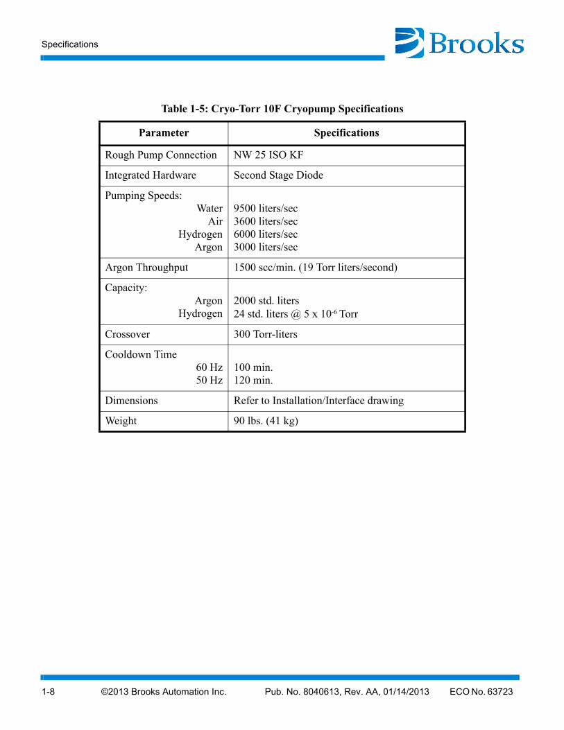
Table 1-5: Cryo-Torr 10F Cryopump Specifications
Parameter Specifications
Rough Pump Connection NW 25 ISO KF
Integrated Hardware Second Stage Diode
Pumping Speeds:Water
AirHydrogen
Argon
9500 liters/sec3600 liters/sec6000 liters/sec3000 liters/sec
Argon Throughput 1500 scc/min. (19 Torr liters/second)
Capacity:Argon
Hydrogen2000 std. liters24 std. liters @ 5 x 10⁻⁶ Torr
Crossover 300 Torr-liters
Cooldown Time 60 Hz 50 Hz
100 min.120 min.
Dimensions Refer to Installation/Interface drawing
Weight 90 lbs. (41 kg)
©2013 Brooks Automation Inc. Pub. No. 8040613, Rev. AA, 01/14/2013 ECO No. 63723 1-9
Cryo-Torr® Pump Installation, Operation and Maintenance Instructions
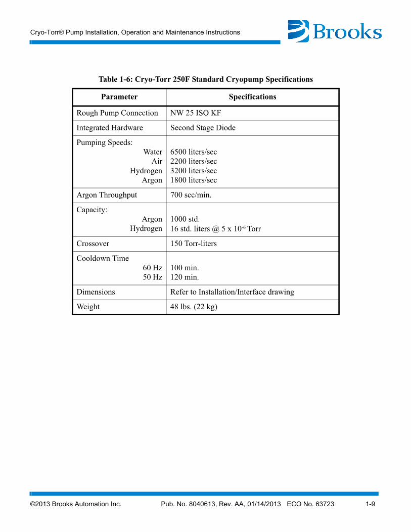
Table 1-6: Cryo-Torr 250F Standard Cryopump Specifications
Parameter Specifications
Rough Pump Connection NW 25 ISO KF
Integrated Hardware Second Stage Diode
Pumping Speeds:Water
AirHydrogen
Argon
6500 liters/sec2200 liters/sec3200 liters/sec1800 liters/sec
Argon Throughput 700 scc/min.
Capacity:Argon
Hydrogen1000 std.16 std. liters @ 5 x 10⁻⁶ Torr
Crossover 150 Torr-liters
Cooldown Time 60 Hz 50 Hz
100 min.120 min.
Dimensions Refer to Installation/Interface drawing
Weight 48 lbs. (22 kg)
Specifications
1-10 ©2013 Brooks Automation Inc. Pub. No. 8040613, Rev. AA, 01/14/2013 ECO No. 63723
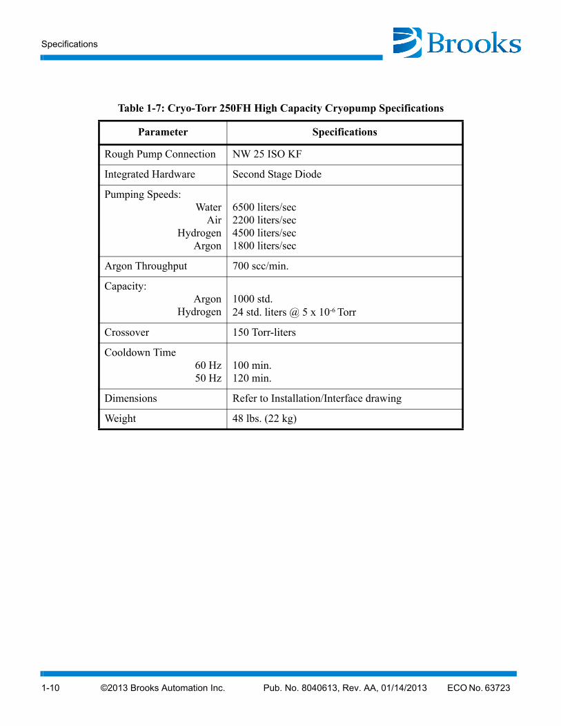
Table 1-7: Cryo-Torr 250FH High Capacity Cryopump Specifications
Parameter Specifications
Rough Pump Connection NW 25 ISO KF
Integrated Hardware Second Stage Diode
Pumping Speeds:Water
AirHydrogen
Argon
6500 liters/sec2200 liters/sec4500 liters/sec1800 liters/sec
Argon Throughput 700 scc/min.
Capacity:Argon
Hydrogen1000 std.24 std. liters @ 5 x 10⁻⁶ Torr
Crossover 150 Torr-liters
Cooldown Time 60 Hz 50 Hz
100 min.120 min.
Dimensions Refer to Installation/Interface drawing
Weight 48 lbs. (22 kg)
©2013 Brooks Automation Inc. Pub. No. 8040613, Rev. AA, 01/14/2013 ECO No. 63723 1-11
Cryo-Torr® Pump Installation, Operation and Maintenance Instructions
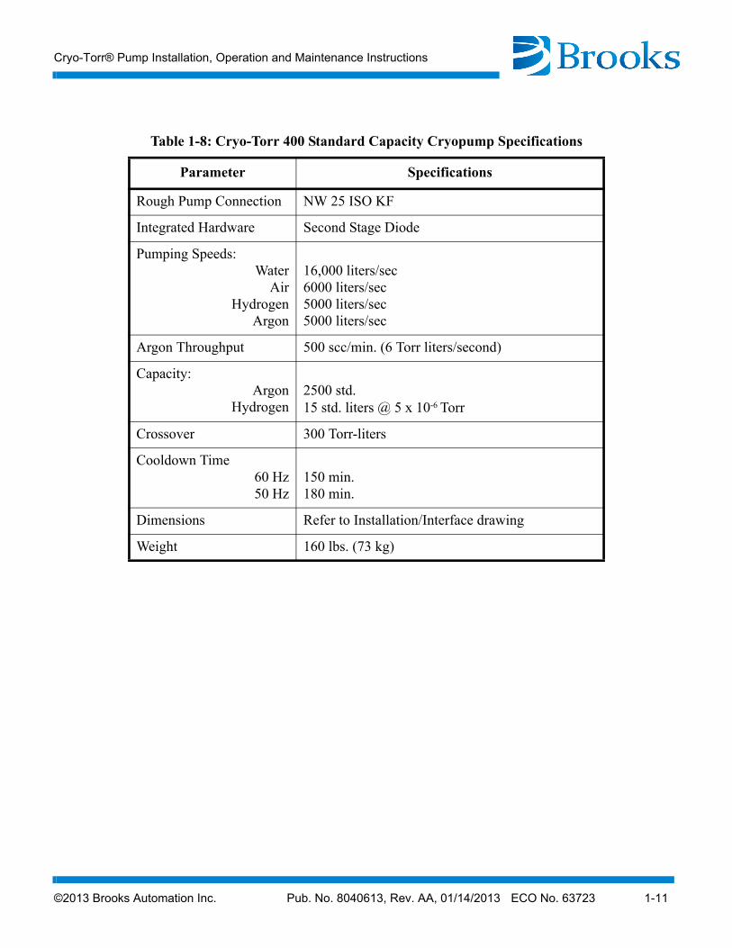
Table 1-8: Cryo-Torr 400 Standard Capacity Cryopump Specifications
Parameter Specifications
Rough Pump Connection NW 25 ISO KF
Integrated Hardware Second Stage Diode
Pumping Speeds:Water
AirHydrogen
Argon
16,000 liters/sec6000 liters/sec5000 liters/sec5000 liters/sec
Argon Throughput 500 scc/min. (6 Torr liters/second)
Capacity:Argon
Hydrogen2500 std.15 std. liters @ 5 x 10⁻⁶ Torr
Crossover 300 Torr-liters
Cooldown Time 60 Hz 50 Hz
150 min.180 min.
Dimensions Refer to Installation/Interface drawing
Weight 160 lbs. (73 kg)

Specifications
1-12 ©2013 Brooks Automation Inc. Pub. No. 8040613, Rev. AA, 01/14/2013 ECO No. 63723
Table 1-9: Cryo-Torr 400 High Capacity Cryopump Specifications
Parameter Specifications
Rough Pump Connection NW 25 ISO KF
Integrated Hardware Second Stage Diode
Pumping Speeds:Water
AirHydrogen
Argon
16,000 liters/sec6000 liters/sec12,000 liters/sec5000 liters/sec
Argon Throughput 500 scc/min. (6 Torr liters/second)
Capacity:Argon
Hydrogen2500 std.42 std. liters @ 5 x 10⁻⁶ Torr
Crossover 300 Torr-liters
Cooldown Time 60 Hz 50 Hz
150 min.180 min.
Dimensions Refer to Installation/Interface drawing
Weight 160 lbs. (73 kg)
©2013 Brooks Automation Inc. Pub. No. 8040613, Rev. AA, 01/14/2013 ECO No. 63723 1-13
Cryo-Torr® Pump Installation, Operation and Maintenance Instructions
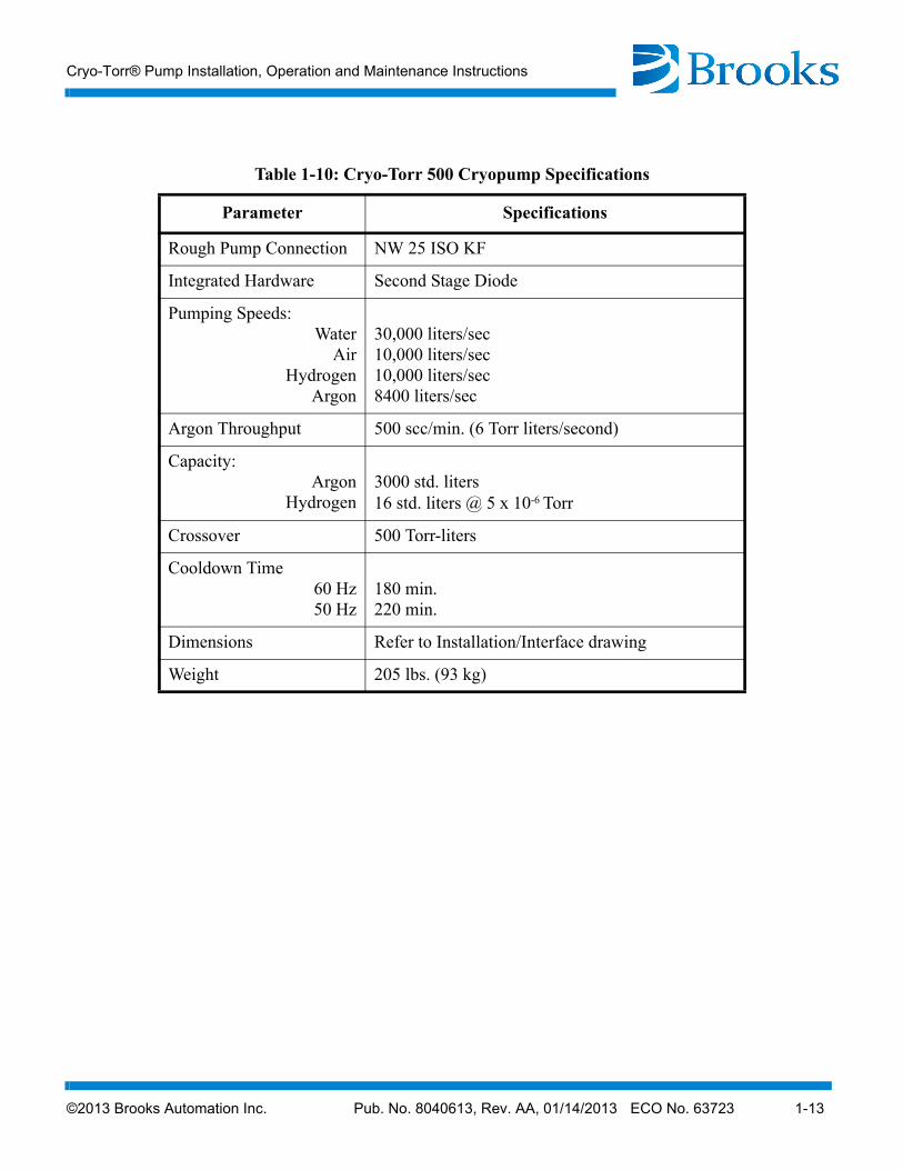
Table 1-10: Cryo-Torr 500 Cryopump Specifications
Parameter Specifications
Rough Pump Connection NW 25 ISO KF
Integrated Hardware Second Stage Diode
Pumping Speeds:Water
AirHydrogen
Argon
30,000 liters/sec10,000 liters/sec10,000 liters/sec8400 liters/sec
Argon Throughput 500 scc/min. (6 Torr liters/second)
Capacity:Argon
Hydrogen3000 std. liters16 std. liters @ 5 x 10⁻⁶ Torr
Crossover 500 Torr-liters
Cooldown Time 60 Hz 50 Hz
180 min.220 min.
Dimensions Refer to Installation/Interface drawing
Weight 205 lbs. (93 kg)
Specifications
1-14 ©2013 Brooks Automation Inc. Pub. No. 8040613, Rev. AA, 01/14/2013 ECO No. 63723
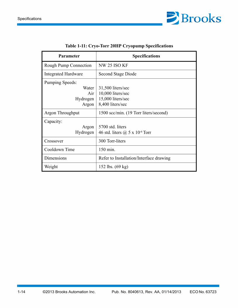
Table 1-11: Cryo-Torr 20HP Cryopump Specifications
Parameter Specifications
Rough Pump Connection NW 25 ISO KF
Integrated Hardware Second Stage Diode
Pumping Speeds:Water
AirHydrogen
Argon
31,500 liters/sec10,000 liters/sec15,000 liters/sec8,400 liters/sec
Argon Throughput 1500 scc/min. (19 Torr liters/second)
Capacity:Argon
Hydrogen5700 std. liters46 std. liters @ 5 x 10⁻⁶ Torr
Crossover 300 Torr-liters
Cooldown Time 150 min.
Dimensions Refer to Installation/Interface drawing
Weight 152 lbs. (69 kg)
©2013 Brooks Automation Inc. Pub. No. 8040613, Rev. AA, 01/14/2013 ECO No. 63723 1-15
Cryo-Torr® Pump Installation, Operation and Maintenance Instructions
Theory of Operation
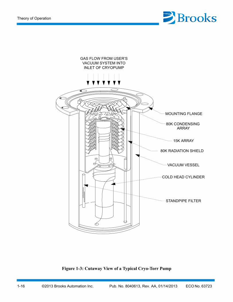
Your Cryo-Torr Cryopump consists of a cold head and a vacuum vessel. An 80K condensing array, a 15K array, cold head station heaters, and an 80K radiation shield are located in the vacuum vessel. The cold station heaters and 15K array are secured to the cold head, which is welded to the vacuum vessel. The cold head provides cooling to the three arrays. Gases are removed from your vacuum chamber, thereby creating a vacuum when they are condensed or adsorbed on the cryogenically-cooled arrays.
Cold Head
The cold head consists of a two-stage cold head cylinder (part of the vacuum vessel) and drive unit displacer assembly, that together produce closed-cycle refrigeration at temperatures that range from 60 to 120K for the first-stage cold station to 10 to 20K for the second-stage cold station, depending on operating conditions. Within the drive unit displacer assembly, the drive unit actuates the displacer-regenerator assembly located in the cold head cylinder and thereby controls the flow of helium into the cold head. Within the drive unit are located the crankcase and drive motor, which is a direct-drive constant-speed motor, operating at 72 rpm on 60Hz power and 60 rpm on 50 Hz power.
During operation, high pressure helium from the compressor enters the cold head at the helium supply connector, and flows through the displacer-regenerator assembly, crankcase, and motor housing before exiting through the helium gas return connector and returning to the compressor. Helium expansion in the displacer-regenerator assembly provides cooling at the first and second stage cold stations.
Vacuum Vessel and Arrays
The 80K condensing array, as shown in Figure 1-3, condenses water and hydrocarbon vapors. The 15K array condenses nitrogen, oxygen, and argon while the specially processed charcoal of this array traps helium, hydrogen, and neon.
Theory of Operation
1-16 ©2013 Brooks Automation Inc. Pub. No. 8040613, Rev. AA, 01/14/2013 ECO No. 63723
Figure 1-3:
GAS FLOW FROM USER’SVACUUM SYSTEM INTOINLET OF CRYOPUMP
MOUNTING FLANGE
80K CONDENSING
15K ARRAY
80K RADIATION SHIELD
VACUUM VESSEL
COLD HEAD CYLINDER
STANDPIPE FILTER
ARRAY
Cutaway View of a Typical Cryo-Torr Pump
©2013 Brooks Automation Inc. Pub. No. 8040613, Rev. AA, 01/14/2013 ECO No. 63723 1-17
Cryo-Torr® Pump Installation, Operation and Maintenance Instructions
Compressor Gas and Oil Flows
Helium returning from the cryopump cold head enters the compressor, and a small quantity of oil is injected into the gas stream, thereby overcoming helium's low specific heat and inability to carry heat produced during compression. Helium is then compressed and passed through a heat exchanger for removal of compression-caused heat.
The helium continues its flow through an oil-mist separator and a charcoal filter adsorber (cartridge), within the compressor, where oil and contaminants are removed. A differential pressure relief valve in the compressor limits the operating pressure differential between the helium supply and return lines, thereby allowing compressor operation without cold head operation. When cold head operation reaches a steady-stage condition, further pressure regulation is unnecessary.
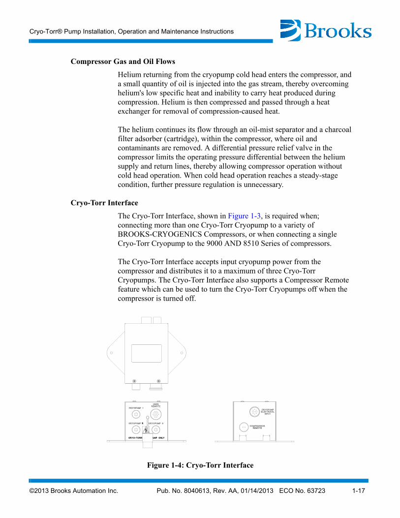
Cryo-Torr Interface
The Cryo-Torr Interface, shown in Figure 1-3, is required when; connecting more than one Cryo-Torr Cryopump to a variety of BROOKS-CRYOGENICS Compressors, or when connecting a single Cryo-Torr Cryopump to the 9000 AND 8510 Series of compressors.
The Cryo-Torr Interface accepts input cryopump power from the compressor and distributes it to a maximum of three Cryo-Torr Cryopumps. The Cryo-Torr Interface also supports a Compressor Remote feature which can be used to turn the Cryo-Torr Cryopumps off when the compressor is turned off.
Figure 1-4: Cryo-Torr Interface
Theory of Operation
1-18 ©2013 Brooks Automation Inc. Pub. No. 8040613, Rev. AA, 01/14/2013 ECO No. 63723
Figure 1-5:
USER’SVACUUM
CHAMBER
CR
YO
-TO
RR
PO
WE
R C
AB
LE
HELIUM SUPPLY LINE
HELIUM RETURN LINE
9600 COMPRESSORCRYO-TORR 10 CRYOPUMP
CRYO-TORR POWER CABLE
INTERFACECRYO-TORR
208 VACCOOLING
WATER
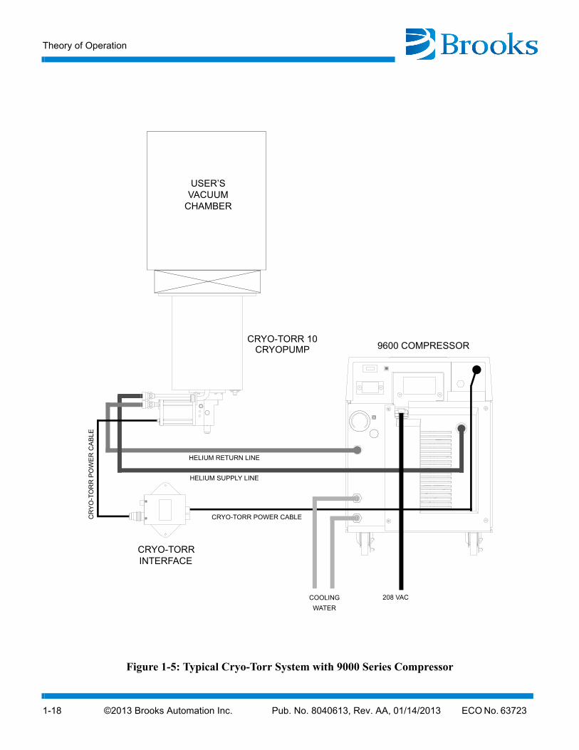
Typical Cryo-Torr System with 9000 Series Compressor
©2013 Brooks Automation Inc. Pub. No. 8040613, Rev. AA, 01/14/2013 ECO No. 63723 1-19
Cryo-Torr® Pump Installation, Operation and Maintenance Instructions
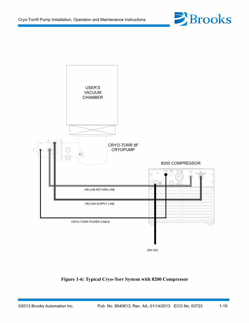
Figure 1-6: Typical Cryo-Torr System with 8200 Compressor
USER’SVACUUM
CHAMBER
CRYO-TORR POWER CABLE
HELIUM SUPPLY LINE
HELIUM RETURN LINE
8200 COMPRESSOR
CRYO-TORR 8F CRYOPUMP
208 VAC
Theory of Operation
1-20 ©2013 Brooks Automation Inc. Pub. No. 8040613, Rev. AA, 01/14/2013 ECO No. 63723
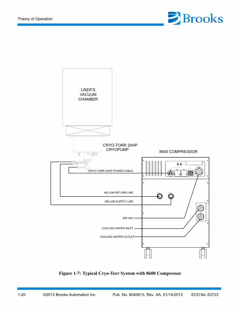
Figure 1-7: Typical Cryo-Torr System with 8600 Compressor
USER’SVACUUM
CHAMBER
CRYO-TORR 20HP POWER CABLE
HELIUM SUPPLY LINE
HELIUM RETURN LINE
8600 COMPRESSOR
CRYO-TORR 20HP CRYOPUMP
208 VAC
COOLING WATER INLET
COOLING WATER OUTLET
©2013 Brooks Automation Inc. Pub. No. 8040613, Rev. AA, 01/14/2013 ECO No. 63723 2-1
Cryo-Torr® Pump Installation, Operation and Maintenance Instructions
Section 2 - Installation
Introduction
Installation information is presented for experienced and non-experienced Cryo-Torr Cryopump system technicians. The flowchart in Figure 2-1 highlights the major tasks for installation of Cryo-Torr Cryopumps. Refer to Figure 2-1 and the appropriate installation procedure within this section for the type of cryopump being installed.
Figure 2-1: Block Diagram for Cryo-Torr System Installation
Installation(Refer to 2-2)
Roughing Pump Connections(Refer to 2-2)
Purge GasConnections(Refer to 2-3)
Power Cable Connection
(Refer to 2-5)
Vent Pipe Connections(Refer to 2-2)
Helium Line Connections(Refer to 2-5)
Determine CrossoverPressure
(Refer to 2-5)
Storage(Refer to 2-10)
Shutdown Cryopump(Refer to 2-9)
Start-up Cryopump(Refer to 2-8)
Installation
2-2 ©2013 Brooks Automation Inc. Pub. No. 8040613, Rev. AA, 01/14/2013 ECO No. 63723
Installation
The cryopump may be installed in any orientation without affecting its performance.
Before mounting the cryopump to the vacuum system, a high-vacuum isolation valve (Hi-Vac valve) should be installed between the cryopump and vacuum chamber to isolate the cryopump from the chamber during rough pumping, cooldown, and regeneration.
Install the cryopump to the vacuum system as follows:
1. Remove the protective cover from the main flange of the cryopump.
2. Clean all sealing surfaces and install the O-ring or metal seal gasket as appropriate.
3. Mount the cryopump to the Hi-Vac valve or vacuum chamber mounting flange. Follow the mating flange manufacturer’s recommendations for the required hardware and securing procedures. Use all of the required mounting hardware.
Vent Pipe Connection
The cryopump pressure relief valve can be vented directly into the room or can be connected to an exhaust system.
When connecting a vent pipe to your cryopump, the 1.30-inch diameter x 1.38-inch long volume around the relief valve must remain open for proper relief valve operation.
Vent pipe adapters are available from BROOKS-CRYOGENICS (P/N 8080250K008).
Roughing Pump Connection
Connect your Cryo-Torr Cryopump to a roughing pump system using a roughing line with the largest inside diameter possible to minimize the
WARNING
If toxic, corrosive, or flammable gases are pumped, a vent pipe must be connected to the cryopump relief valve and directed to a safe location.
©2013 Brooks Automation Inc. Pub. No. 8040613, Rev. AA, 01/14/2013 ECO No. 63723 2-3
Cryo-Torr® Pump Installation, Operation and Maintenance Instructions
roughing time required during start-up procedures prior to normal operation. The roughing pump should have a blank-off pressure of less than 20 microns. The roughing pump connects to the Cryo-Torr Cryopump roughing valve. The valve will accept an ISO NW-25 flange.
A molecular sieve roughing trap to minimize oil backstreaming from your roughing pump system is recommended and should be installed in the roughing pump line near the roughing pump. The trap must be properly maintained. Connect the roughing valve to the roughing pump as follows:
1. Install the roughing pump line to the cryopump roughing valve port using the clamp provided. Tighten the clamp securely.
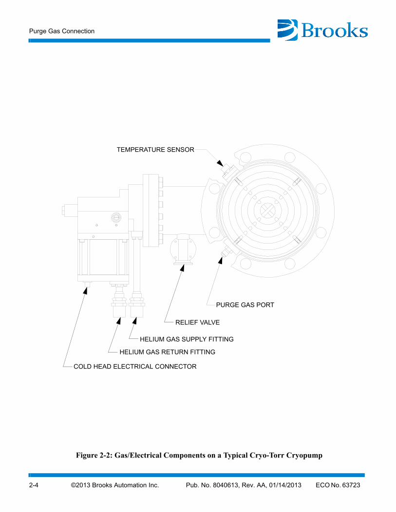
Purge Gas Connection
Connect your purge gas supply line to the purge valve 1/8 NPTF fitting. Adjust the supply pressure to achieve 1-2 cfm.
Purge Gas Connection
2-4 ©2013 Brooks Automation Inc. Pub. No. 8040613, Rev. AA, 01/14/2013 ECO No. 63723
Figure 2-2:
HELIUM GAS RETURN FITTING
HELIUM GAS SUPPLY FITTING
TEMPERATURE SENSOR
COLD HEAD ELECTRICAL CONNECTOR
PURGE GAS PORT
RELIEF VALVE
Gas/Electrical Components on a Typical Cryo-Torr Cryopump
©2013 Brooks Automation Inc. Pub. No. 8040613, Rev. AA, 01/14/2013 ECO No. 63723 2-5
Cryo-Torr® Pump Installation, Operation and Maintenance Instructions
Helium Return and Supply Line Connections
Make the connections between the cryopump and compressor. Refer to Figure 2-2, while making the component interconnections.
1. Remove all dust plugs and caps from the supply and return lines, compressor, and cryopump. Check all fittings.
2. Connect the helium-return line from the gas-return connector on the rear of the compressor to the gas-return connector on the Cryo-Torr Cryopump.
3. Connect the helium supply line from the supply connector on the cartridge to the gas-supply connector on the Cryo-Torr Cryopump.
4. Attach the supply and return line identification decals (BROOKS-CRYOGENICS supplied) to their respective connecting piping ends.
NOTE: Verify proper helium supply static pressure as described in the Installation Section of the appropriate Compressor Manual.
Power Cable Connection
CAUTION
The system power circuit breaker switch at the back of the compressor must be in the OFF position before making any and all electrical connections.
Do not connect the compressor to its power source until all connections have been made between the components of the Cryo-Torr system.
1. Connect the Cryo-Torr power cable from the cold head connector on the compressor to the Cryo-Torr Cryopump power connector.
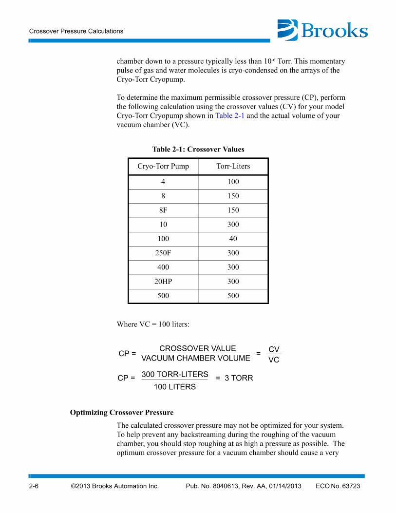
Crossover Pressure Calculations
Crossover is that point in time when the pumping of a vacuum chamber is switched from rough pumping to high-vacuum pumping. Rough pumping brings the vacuum chamber pressure from one atmosphere (760 Torr) down to a pressure of approximately 0.5 Torr. At crossover, the roughing valve is closed and the high vacuum valve is opened bringing the vacuum
Crossover Pressure Calculations
2-6 ©2013 Brooks Automation Inc. Pub. No. 8040613, Rev. AA, 01/14/2013 ECO No. 63723
chamber down to a pressure typically less than 10-6 Torr. This momentary pulse of gas and water molecules is cryo-condensed on the arrays of the Cryo-Torr Cryopump.
To determine the maximum permissible crossover pressure (CP), perform the following calculation using the crossover values (CV) for your model Cryo-Torr Cryopump shown in Table 2-1 and the actual volume of your vacuum chamber (VC).
Where VC = 100 liters:
Optimizing Crossover Pressure
The calculated crossover pressure may not be optimized for your system. To help prevent any backstreaming during the roughing of the vacuum chamber, you should stop roughing at as high a pressure as possible. The optimum crossover pressure for a vacuum chamber should cause a very
Table 2-1: Crossover Values
Cryo-Torr Pump Torr-Liters
4 100
8 150
8F 150
10 300
100 40
250F 300
400 300
20HP 300
500 500
CP = CROSSOVER VALUE
VACUUM CHAMBER VOLUME= CV
VC
CP = 300 TORR-LITERS
100 LITERS3 TORR=
©2013 Brooks Automation Inc. Pub. No. 8040613, Rev. AA, 01/14/2013 ECO No. 63723 2-7
Cryo-Torr® Pump Installation, Operation and Maintenance Instructions
slight rise in temperature with a rapid recovery. Increase the roughing pressure in small increments (15-20%) until the rise in temperature is noted; then drop the value by a small amount (10%). This will be the optimum pressure for that vacuum chamber.
Cryo-Torr Cryopump Capacity Calculations
Cryopump capacity is defined as the total standard liters of gas that can be accommodated within a cryopump prior to regeneration. The number of hours between regeneration cycles can be easily calculated in the case of a continuous gas flow of a known gas species:
Where:
A = Duration of operation with a continuous gas flow (hours)
B = Gas flow (scc/min.)
C = Cryo-Torr capacity for the particular gas species being flowed (std. liters) as shown in Table 2-2.
Table 2-2: Condensable Gases Capacity (Argon, Nitrogen, Oxygen, etc.)
Parameter Value
Cryopump Cryo-Torr 10F
Standard Liters 2000
Torr-Liters 1,500,000
A = 16.6 x C
B
Crossover Cycle Calculations
2-8 ©2013 Brooks Automation Inc. Pub. No. 8040613, Rev. AA, 01/14/2013 ECO No. 63723
Example:
For a sputtering application of continuously flowing argon gas at 70 scc/min, the duration of continuous operation with this gas flow (between regeneration) would be:
Crossover Cycle Calculations
The number of crossover cycles between regeneration cycles can also be easily calculated when the crossover pressure and vacuum chamber volume are known:
Where:
N = Number of crossover cycles
V = Volume of vacuum chamber (liters)
P = Pressure of vacuum chamber prior to crossover (Torr) (roughing pressure)
Example:
For a vacuum chamber of 100 liters and a roughing pressure of 1.5 Torr, the number of crossover cycles between regeneration cycles would be:
Cryopump Start-up Procedure
1. Close the Hi-Vac valve to isolate the Cryo-Torr Cryopump.
2. Initiate a Nitrogen purge of the Cryo-Torr Cryopump for one hour.
A = 16.6 x 2000 (std liters)
70 (scc/min)474 hours=
N = 760,000 Torr-liters
P x V
N = 760,000 Torr-liters
1.5 (Torr) x 100 (liters)= 5,060 cycles
©2013 Brooks Automation Inc. Pub. No. 8040613, Rev. AA, 01/14/2013 ECO No. 63723 2-9
Cryo-Torr® Pump Installation, Operation and Maintenance Instructions
3. Open the roughing valve and rough the Cryo-Torr Cryopump to 50 microns. Close the roughing valve.
NOTE: If step 4 cannot be achieved, repeat step 3.
4. Check the rate-of-rise. The rate-of-rise should be 10 microns/min-ute.
NOTE: Cryo-Torr Cryopump power is turned ON/OFF when compressor power is turned ON/OFF.
5. Turn compressor power ON.
6. Wait for the second stage temperature (T2) to be less than 17 K.
7. Open the Hi-Vac valve.
Cryopump Shutdown Procedure
Typically, a cryopump can be left in operation continuously if you are not processing or not using the vacuum chamber, by simply closing the Hi-Vac value to isolate the cryopump from your vacuum chamber. You are now able to load, unload, repair or replace components in the chamber and the cryopump will be available for restarting the process as necessary.
1. Close the Hi-Vac valve to isolate the cryopump.
2. Shut off the cryopump by removing the input power cable to the cryopump motor.
3. Initiate Nitrogen gas purge.
4. Continue Nitrogen gas purge until ambient temperature is reached.
5. Shut off the Nitrogen gas purge.
Cryopump Storage
2-10 ©2013 Brooks Automation Inc. Pub. No. 8040613, Rev. AA, 01/14/2013 ECO No. 63723
Cryopump Storage
WARNING
If the cryopump has been used to pump toxic or dangerous materials, you must take adequate precautions to safeguard personnel. If such a cryopump is shipped to a Product Service Department, clearly mark on all storage cartons the identity of the toxic or dangerous materials to which the cryopump has been subjected. All shipped equipment that contains hazardous/toxic materials must conform to DOT regulations.
If the cryopump is stored while attached to your vacuum system, the cryopump vacuum vessel should be kept at a slight positive atmospheric pressure with dry nitrogen or argon.
If the cryopump is removed from your vacuum system, install the protective cover on the mounting flange of the cryopump vacuum vessel inlet before storage.
The remaining components of your Cyro-Torr high vacuum pump system are fully protected during storage if kept under positive helium pressure and all component connections left connected. Periodically, check the helium supply pressure gauge on the compressor and refer to the compressor manual for the proper static charge pressure.
©2013 Brooks Automation Inc. Pub. No. 8040613, Rev. AA, 01/14/2013 ECO No. 63723 3-1
Cryo-Torr® Pump Installation, Operation and Maintenance Instructions
Section 3 - Regeneration
Introduction
A Cryo-Torr cryopump periodically requires a regeneration cycle to return it to its original operating capabilities.
Gases captured from a vacuum chamber and trapped in the cryopump through condensation and cryo-adsorption are held primarily in an ice-like form. A regeneration cycle removes trapped gases through a process similar to defrosting a refrigerator freezer compartment.
During a regeneration cycle, the cryopump is warmed to room temperature or higher, allowing trapped gases to change from a solid state to a gaseous state and thereby released from the cryopump through the pressure relief valve to the atmosphere.
When to Regenerate
The need to regenerate the Cryo-Torr pump as a result of saturation is a function of the cryopump capacity and the process gas throughput.
If the cryopump becomes incapable of maintaining a high-vacuum (typically an increase in your vacuum chamber base pressure by a factor of 10, even though the cold head and compressor unit are operating satisfactorily), the cryopump requires regeneration.
It is recommended that your cryopump be regenerated on a regular schedule coinciding with system maintenance, weekend system shutdown, etc. A suitable time interval between regeneration cycles can be determined from experience.
Extended loss of electrical power (10 minutes or longer), system vacuum failure, such as venting with a partially open vacuum isolation valve, and operator error may necessitate cryopump regeneration.
WARNING
If toxic, corrosive, or flammable gases are pumped, a vent pipe must be connected to the
Assisted Regeneration
3-2 ©2013 Brooks Automation Inc. Pub. No. 8040613, Rev. AA, 01/14/2013 ECO No. 63723
NOTE: Short term electrical outages of up to 10 minutes should not result in the need to regenerate your cryopump.
Assisted Regeneration
A regeneration cycle incorporating the use of a heated dry inert purge gas (nitrogen/argon) is the preferred method of regeneration and will overcome unassisted regeneration technical difficulties by:
• Minimizing the required time to bring the condensing and cryo-adsorbing arrays to room temperature
• Reducing the time required to rough the cryopump because the dry inert purge gas will minimize the amount of residual water vapor in the 15K array
• Diluting hazardous gases and ensuring their removal from the cryopump housing
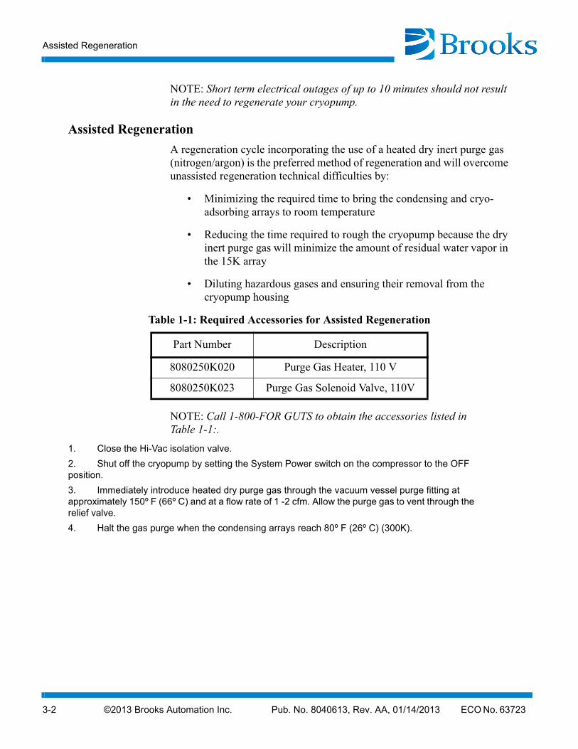
NOTE: Call 1-800-FOR GUTS to obtain the accessories listed in Table 1-1:.
1. Close the Hi-Vac isolation valve.
2. Shut off the cryopump by setting the System Power switch on the compressor to the OFF position.
3. Immediately introduce heated dry purge gas through the vacuum vessel purge fitting at approximately 150º F (66º C) and at a flow rate of 1 -2 cfm. Allow the purge gas to vent through the relief valve.
4. Halt the gas purge when the condensing arrays reach 80º F (26º C) (300K).
Table 1-1: Required Accessories for Assisted Regeneration
Part Number Description
8080250K020 Purge Gas Heater, 110 V
8080250K023 Purge Gas Solenoid Valve, 110V
©2013 Brooks Automation Inc. Pub. No. 8040613, Rev. AA, 01/14/2013 ECO No. 63723 3-3
Cryo-Torr® Pump Installation, Operation and Maintenance Instructions
5. When the condensing arrays reach ambient temperature, rough the cryopump to an initial starting pressure, usually between 50 and 100 microns.
NOTE: After roughing, perform a rate-of-rise (ROR) test to ensure that your cryopump regeneration has been thorough and that no air-to-vacuum leaks are present.
6. Perform the rate-of-rise test as follows:
a. Once the roughing cycle has roughed the cryopump starting pressure to between 50 - 100 microns, close the roughing valve.
b. Observe the rate of pressure rise (ROR) over a five minute period.
NOTE: The ROR should be less than 10 microns/minute over a five minute period (50 microns total).
c. If the ROR is greater than 50 microns, repurge the cryopump, check for leaks, and repeat steps 5 and 6.
7. Close the cryopump roughing valve and start the cryopump.
8. The cryopump is ready for use when the second stage array reaches a temperature of 20K or lower.

This Page Intentionally Left Blank
©2013 Brooks Automation Inc. Pub. No. 8040613, Rev. AA, 01/14/2013 ECO No. 63723 4-1
Cryo-Torr® Pump Installation, Operation and Maintenance Instructions
Section 4 - Troubleshooting
Troubleshooting the Cryopump
The primary indication of trouble in a vacuum pumping system is a rise in base pressure in your vacuum chamber. A rise in the base pressure may be caused by a leak in the vacuum system or by a fault in the cryopump or saturation of the 15K cryo-adsorbing charcoal array (regeneration may be necessary). If the cryopump temperature is below 20K it must pump at rated capacity; a high base pressure is usually caused by an air-to-vacuum leak in the system.
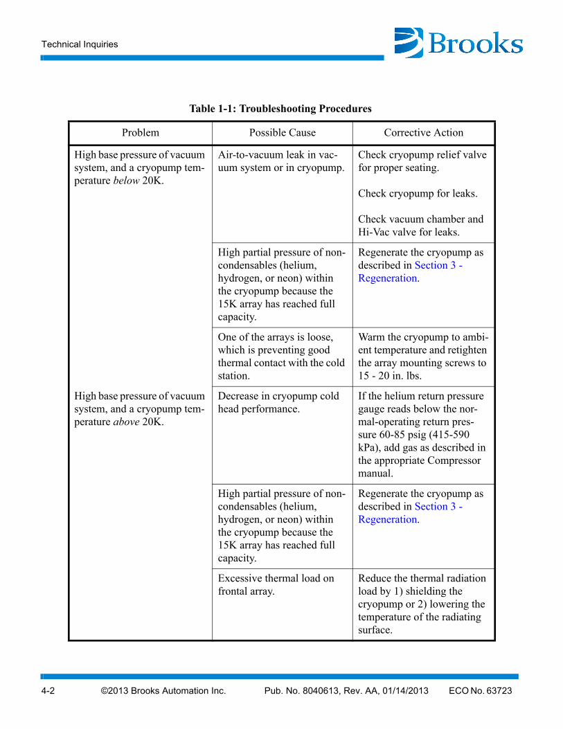
If you suspect a leak in your vacuum system, isolate the cryopump by closing the Hi-Vac valve and leak check your vacuum chamber. If no leaks are found, a leak may be present below the Hi-Vac valve (cryopump). Leak checking below the Hi-Vac valve should be performed with the cryopump shut OFF and at room temperature. Leak checking while the cryopump is operating may mask leaks that are present (due to the ability of the cryopump to pump helium). If no leak is found, refer to the cryopump troubleshooting procedures summarized in Table 1.
The problems presented in Table 1 are followed by possible causes and corrective actions. The causes and corresponding actions are listed in their order of probability of occurrence.
Maintaining a log of certain parameters during normal operation can be a valuable tool in troubleshooting the cryopump. The log may contain many parameters, however, the following minimum parameters should be included: the cooldown time to 20K, the roughing time to 50μ, the time to base pressure at crossover, the time between regeneration cycles, and the compressor pressure reading.
Technical Inquiries
Please refer to Appendix A of this manual for a complete list of the BROOKS-CRYOGENICS' world wide customer support centers.
Technical Inquiries
4-2 ©2013 Brooks Automation Inc. Pub. No. 8040613, Rev. AA, 01/14/2013 ECO No. 63723
Table 1-1: Troubleshooting Procedures
Problem Possible Cause Corrective Action
High base pressure of vacuum system, and a cryopump tem-perature below 20K.
Air-to-vacuum leak in vac-uum system or in cryopump.
Check cryopump relief valve for proper seating.
Check cryopump for leaks.
Check vacuum chamber and Hi-Vac valve for leaks.
High partial pressure of non-condensables (helium, hydrogen, or neon) within the cryopump because the 15K array has reached full capacity.
Regenerate the cryopump as described in Section 3 - Regeneration.
One of the arrays is loose, which is preventing good thermal contact with the cold station.
Warm the cryopump to ambi-ent temperature and retighten the array mounting screws to 15 - 20 in. lbs.
High base pressure of vacuum system, and a cryopump tem-perature above 20K.
Decrease in cryopump cold head performance.
If the helium return pressure gauge reads below the nor-mal-operating return pres-sure 60-85 psig (415-590 kPa), add gas as described in the appropriate Compressor manual.
High partial pressure of non-condensables (helium, hydrogen, or neon) within the cryopump because the 15K array has reached full capacity.
Regenerate the cryopump as described in Section 3 - Regeneration.
Excessive thermal load on frontal array.
Reduce the thermal radiation load by 1) shielding the cryopump or 2) lowering the temperature of the radiating surface.
©2013 Brooks Automation Inc. Pub. No. 8040613, Rev. AA, 01/14/2013 ECO No. 63723 4-3
Cryo-Torr® Pump Installation, Operation and Maintenance Instructions
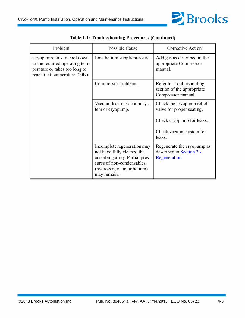
Cryopump fails to cool down to the required operating tem-perature or takes too long to reach that temperature (20K).
Low helium supply pressure. Add gas as described in the appropriate Compressor manual.
Compressor problems. Refer to Troubleshooting section of the appropriate Compressor manual.
Vacuum leak in vacuum sys-tem or cryopump.
Check the cryopump relief valve for proper seating.
Check cryopump for leaks.
Check vacuum system for leaks.
Incomplete regeneration may not have fully cleaned the adsorbing array. Partial pres-sures of non-condensables (hydrogen, neon or helium) may remain.
Regenerate the cryopump as described in Section 3 - Regeneration.
Table 1-1: Troubleshooting Procedures (Continued)
Problem Possible Cause Corrective Action

This Page Intentionally Left Blank
©2013 Brooks Automation Inc. Pub. No. 8040613, Rev. AA, 01/14/2013 ECO No. 63723 5-1
Cryo-Torr® Pump Installation, Operation and Maintenance Instructions
Section 5 - Maintenance Procedures
Helium Circuit Decontamination
Contamination of the helium-gas circuit is indicated by sluggish or intermittent operation (ratchetting) of the cold head drive mechanism. With severe contamination the cold head drive may seize and fail to operate. One of the major sources of contamination is using helium gas of less than the required purity. When performing the decontamination process, use only 99.999% pure-helium gas, and the regulator and charging line must be properly connected and purged.
This decontamination procedure will remove contaminants from the cold head and/or compressor, thereby restoring system performance. The cold-trapping of contaminants inside the cold head during this procedure will also decontaminate the compressor if the contamination of the system is not severe. Separate decontamination of the compressor is required whenever the compressor has been opened to atmosphere, or the pressure dropped to zero.
Cryo-Torr Cryopump Decontamination Procedures
NOTE: Refer also to the appropriate Compressor Manual.
1. Cool down the cryopump and operate it for one to three hours. If the system will not cool down, proceed to step 2. Operating the cryopump will isolate the contaminants by "freezing" them in the cold head. The contaminants in the helium-gas circuit of the cryopump tend to become frozen inside the cold head. The longer the cryopump is operated beyond the one-hour period, the greater is the amount of contamination that becomes isolated inside the cold head.
2. Shut down the cryopump as described in Section 2 - Installation.
3. Immediately disconnect the helium supply and return lines from the gas-supply and gas-return connectors at the rear of the compressor. Leave them attached to the cold head.
4. Attach the maintenance manifold to the disconnected ends of the return and supply lines.
Cryo-Torr Cryopump Decontamination Procedures
5-2 ©2013 Brooks Automation Inc. Pub. No. 8040613, Rev. AA, 01/14/2013 ECO No. 63723
5. Reduce the pressure in the cold head to a level of 30 psig by using the maintenance manifold. Reducing the pressure in the cold head to below 30 psig (200 kPa) may introduce more contaminants into the helium circuit.
If you only have the manual regeneration option, turn the cryopump OFF and open the purge valve until the second stage temperature reaches 290K.
6. Attach a two-stage regulator (0-3000/0-400 psig) and charging line to a helium bottle (99.999% pure). DO NOT OPEN THE BOTTLE VALVE AT THIS TIME. Purge the regulator and charging line as introduced in steps a through d below. Do not use helium gas that is less than 99.999% pure.
a. Open the regulator a small amount by turning the adjusting knob clockwise until it contacts the diaphragm; then, turn approximately 1/8 to 1/4 turn more, so that the regulator is barely open.
b. Slowly open the bottle valve, and purge the regulator and line for 10 to 15 seconds. Turn the regulator knob counter-clockwise until the helium stops flowing.
c. Loosely connect the charge line to the 1/8-inch Hoke valve on the maintenance manifold.
d. Purge the charge line again, as in step a, for 30 seconds, and tighten the charge line flare fitting onto the Hoke valve while the helium is flowing.
This procedure is required to ensure that both the regulator and the charging line will be purged of air and that the air trapped in the regulator will not diffuse back into the helium bottle. For best results, BROOKS-CRYOGENICS suggests a dedicated helium bottle, regulator, and line, which are never separated, for adding helium.
7. Perform in sequence:
a. Backfill the cold head with helium to a static charge pres-sure of 195-205 psig (1345-1415 kPa) by adjusting the reg-ulator to the required pressure, and opening the Hoke valve on the manifold. Close the Hoke valve when the pressure is correct.
b. Depressurize the cold head to 30 and 50 psig 200 and 330 kPa) by slowly opening the ball valve and allowing the helium to bleed out slowly. Do not reduce the pressure to less than 30 psig or the cold head may be further contami-nated.
©2013 Brooks Automation Inc. Pub. No. 8040613, Rev. AA, 01/14/2013 ECO No. 63723 5-3
Cryo-Torr® Pump Installation, Operation and Maintenance Instructions
c. Perform the flushing steps a and b four more times.
d. Pressurize the cold head to a static charge pressure of 195-205 psig (1345-1415 kPa) and run the cold head drive motor for 10 to 30 seconds.
e. Perform steps b through d four more times for a total of 25 flushes and 5 drive-motor runs.
8. Verify that the cold head is pressurized to the static charge pressure of 195-205 psig (1345-1415 kPa).
9. Disconnect the maintenance manifold from the helium return and supply lines.
10. Reconnect the helium return and supply lines to the return and sup-ply connectors at the rear of the compressor. The cryopump is now ready for operation.
Cleaning the Cryo-Torr Cryopump
WARNING
If the cryopump has been used to pump toxic or dangerous materials, you must take adequate precautions to safeguard personnel.
Cleaning the arrays or other interior surfaces of the cryopump vacuum vessel is seldom required because dust build-up does not affect performance, and the special alloy copper cryo-condensing arrays are nickel plated for corrosion resistance.
If you wish to clean the arrays and other interior surfaces, follow the procedures below.
1. Confirm that an adequate supply of indium gasket material, P/N 3543738P001, is available to replace gaskets inadvertently damaged during disassembly.
2. Carefully disassemble the components in the vacuum vessel, including the arrays and radiation shield, to avoid damage to the indium gaskets.
3. Clean the interior surface of the vacuum vessel, the 80K condens-ing array, and the 80K radiation shield as follows:
Cleaning the Cryo-Torr Cryopump
5-4 ©2013 Brooks Automation Inc. Pub. No. 8040613, Rev. AA, 01/14/2013 ECO No. 63723
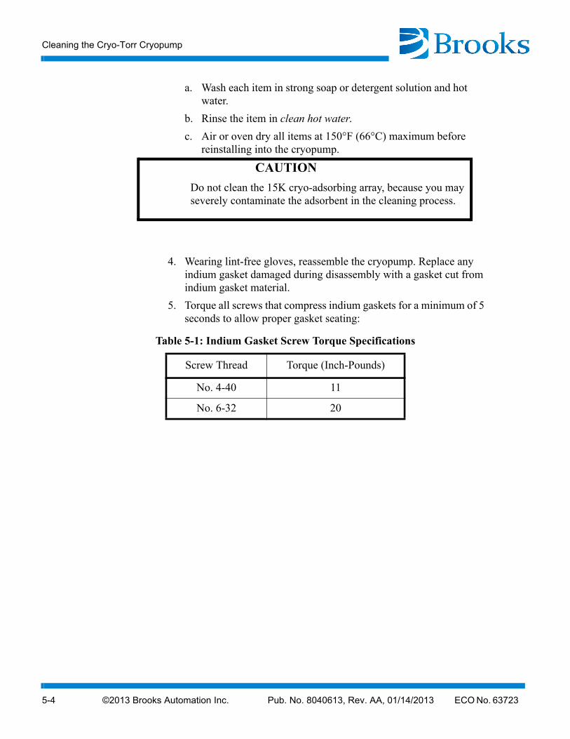
a. Wash each item in strong soap or detergent solution and hot water.
b. Rinse the item in clean hot water.
c. Air or oven dry all items at 150°F (66°C) maximum before reinstalling into the cryopump.
CAUTION
Do not clean the 15K cryo-adsorbing array, because you may severely contaminate the adsorbent in the cleaning process.
4. Wearing lint-free gloves, reassemble the cryopump. Replace any indium gasket damaged during disassembly with a gasket cut from indium gasket material.
5. Torque all screws that compress indium gaskets for a minimum of 5 seconds to allow proper gasket seating:
Table 5-1: Indium Gasket Screw Torque Specifications
Screw Thread Torque (Inch-Pounds)
No. 4-40 11
No. 6-32 20
©2013 Brooks Automation Inc. Pub. No. 8040613, Rev. AA, 01/14/2013 ECO No. 63723 A-1
Cryo-Torr® Pump Installation, Operation and Maintenance Instructions
Appendix A - Customer Brooks Automation Technical Sup-port Information
When contacting Brooks Automation for Technical Support, please have the fol-lowing information available.
1. Record the part number and serial number from the compressor.
2. Provide the installed location of the compressor.
3. Provide name, e-mail address, and telephone number of the person to con-tact.
4. List any error codes received during the failure.
5. Prepare a detailed description of the events relating to the error.
• Time that the equipment has been in operation
• Work that was done on the equipment prior to the error
• Functions that the equipment was performing when the error occurred
• Actions taken after the error and the results of those actions
• Other information that may assist the Specialist
6. Contact Brooks Automation Technical Support at these numbers:
For additional contact information, please go to the Brooks Automation web site at www.brooks.com or send an E-mail to [email protected].
Brooks Location GUTS® Contact Number
North America
1-800-FOR-GUTS (1-800-367-4887) US/Canada+1-978-262-2900
Europe +49 1804 CALL GUTS (+49 1804 2255 4887)Japan +81-45-477-5980China +86-21-5131-7066Taiwan +886-3-552-5225Korea +82-31-288-2500Singapore +65-6464-1481

This Page Intentionally Left Blank
©2013 Brooks Automation Inc. Pub. No. 8040613, Rev. AA, 01/14/2013 ECO No. 63723 Index-1
A
Arrays and vacuum vesseloperation, 1-15
C
Calculationscapacity, 2-7
Capacity calculations, 2-7Cleaning Cryo-Torr pump, 5-3Cold head
operation, 1-15Compressor gas and oil flows
operation, 1-17Crossover cycle
calculations, 2-8Crossover pressure
optimizing, 2-6Crossover pressure calculations, 2-5Cryo-Torr 10
specifications, 1-7Cryo-Torr 10F
specifications, 1-8Cryo-Torr 20HP
specifications, 1-14Cryo-Torr 250F
specifications, 1-9Cryo-Torr 250FH
specifications, 1-10Cryo-Torr 400 High Capacity
specifications, 1-12Cryo-Torr 400 Standard Capacity
specifications, 1-11Cryo-Torr 4F
specifications, 1-4Cryo-Torr 500
specifications, 1-13Cryo-Torr 8
specifications, 1-5Cryo-Torr 8F
specifications, 1-6Cryo-Torr interface, 1-17Cryo-Torr pumps
installation, 2-1introduction, 1-1
theory of operation, 1-15
D
Decontaminationprocedures, 5-1
H
Helium return and supply lineconnections, 2-5
I
Installationcrossover pressure calculations, 2-5helium return and supply line connec-
tions, 2-5power cable connection, 2-5pumps, 2-1purge gas connection, 2-3roughing pump connection, 2-2vent pipe connection, 2-2
Installation, operation, and serviceinstructions, 1-1
InterfaceCryo-Torr, 1-17
M
Maintenance, 5-1cleaning, 5-3decontamination procedures, 5-1helium circuit decontamination, 5-1
O
Oil flows and compressor gasoperation, 1-17
P
Power cable connectioninstallation, 2-5
Purge gas connectioninstallation, 2-3
Index
1-2 ©2013 Brooks Automation Inc. Pub. No. 8040613, Rev. AA, 01/14/2013 ECO No. 63723
R
Regenerationassisted, 3-2introduction, 3-1when to, 3-1
Roughing pump connectioninstallation, 2-2
S
Safety precautions,S-1Shutdown procedure, 2-9Start-up procedure, 2-8Storage, Cryopump, 2-10
T
Theory of operationpumps, 1-15
Troubleshooting, 4-1
V
Vacuum vessel and arraysoperation, 1-15
Vent pipe connectioninstallation, 2-2