Embed Size (px)
Citation preview

Proceedings of 2006 ASME International Mechanical Engineering Congress and Exposition
November 5-10, 2006, Chicago, Illinois, USA
IMECE2006-13214
Crush Analyses of Multi-Level Equipment
Eloy Martinez John Zolock David Tyrell
Volpe National Transportation Systems Center US Department of Transportation
Cambridge, MA 02142 USA
Proceedings of IMECE2006 2006 ASME International Mechanical Engineering Congress and Exposition
November 5-10, 2006, Chicago, Illinois, USA
IMECE2006-13214
ABSTRACT Non-linear large deformation crush analyses were
conducted on a multi-level cab car typical of those in operation by the Southern California Regional Rail Authority (SCRRA) in California. The motivation for these analyses was a collision, which occurred in Placentia, CA, on April 23, 2002. The final deformed state of the leading cab car was unusual. This behavior contrasted with previous testing and analysis experience of single level equipment in collisions. This investigation explores the structural response of multi-level car structures.
The structure of the multi-level equipment differs from single level equipment in that a significant change occurs in the load path from where load enters through the coupler and is subsequently reacted aft of the body bolster of the car. This change in load path results from a change in geometry of the car to accommodate quarter point doors and the upper level of the car. Load enters at the typical coupler height but descends to the lower platform level of the car through a transition structure.
To better understand the influence of the varied geometry, a series of calculations were performed to obtain the force-crush characteristics and modes of deformation for the cab car subjected to a series of different initial conditions. Crush models were developed of both the lead and trailing end of the car, as well as the center section of the car. In addition to these sub-models, a full car model was constructed.
Results from the sub-model analyses indicate that the longitudinal strength of the trailing end is comparable to that of the lead end, and the center section of the car is significantly stronger than either end. This suggests that crush will most likely occur at the ends of the car when it is overloaded. Initial conditions similar to the Placentia, CA accident were also investigated to better understand the atypical mode of
1
deformation that occurred. These results indicated that the multi-level equipment can resist high force levels for longer crush distances than single level platform vehicles but will eventually experience softening behavior, which will result in focused crush at one end of a car.
INTRODUCTION
The Federal Railroad Administration (FRA) has sponsored research into the structural crashworthiness of passenger rail equipment. The goal of such research is to establish the current level of crashworthiness protection of conventional equipment used in commuter and intercity service. FRA may then propose alternative design strategies to better protect the occupied space of passengers and crewmembers and limit the forces that they are subjected to as they ride out a collision or derailment. In addition to developing alternative design strategies, effectiveness studies were also conducted to demonstrate the potential safety benefits for incremental inclusion of structural and/or interior crashworthiness features [1, 2].
In the course of such research, several full-scale tests have been conducted [3, 4, 5]. These tests have focused on representative single level designs used for commuter and intercity travel. As a result of historical practice and industry and Federal requirements, these single level designs are typically of a platform design with a very strong center sill. During the course of a collision with another train, the draft sill buckles after a high load level is reached, and the strength then decreases rapidly and plateaus at a much lower load level. This type of a force-crush characteristic results in focused crush at the impacting interface. The measured results from tests, a review of historical accident data, and observations from current accident investigations confirm this finding [6].
The current study findings presented in this paper expand upon the base of knowledge gained about conventional single
1 Copyright © 2006 by ASME

level equipment to multi-level equipment. This equipment type is becoming increasingly popular and utilized by many operating authorities. Questions have been raised as to whether the multi-level equipment performs in a similar manner as that observed and measured for single level equipment. The answer discussed in greater detail in this paper, is that although differences exist in the designs of single and multi-level equipment, the fundamental response for both sets of equipment are very similar because crush tends to be focused on the lead car in a collision due to uncontrolled deformations that occur for larger crush distances.
The Head-On Accident in Placentia, CA
The motivating event for this study was the head-on accident that occurred in Placentia, CA, on April 23, 2002, between a Metrolink commuter train and a Burlington Northern Santa Fe (BNSF) freight train. The Metrolink commuter train consisted of a cab car, two commuter cars, and a locomotive. The BNSF freight train consisted of a GE Model Dash-9-44CW Diesel Electric locomotive in the lead, two additional locomotives, and 67 loaded cars. Before the collision, the Metrolink locomotive engineer, operating the train in push-mode where the cab car was in the lead position, noted that the BNSF train was on the same set of tracks and placed the Metrolink train in emergency braking. The commuter train came to a full stop, and the locomotive engineer ran back into the car warning passengers of the impending collision. The BNSF locomotive engineer also became aware of the impending collision and placed his train in emergency braking, thereby reducing the potential impact speed from 42 mph to roughly 23 mph. As a result of the collision, approximately 161 people were transported to medical facilities, and two occupants died due to impacts with workstation tables in the lead cab car [7, 8].
Upon impact of the freight train with the Metrolink cab car, car 634, the collision load was transmitted initially through the coupler and then into the cab end frame. The front end of the cab car sustained direct contact damage across the entire width of the car with some deformations in the end frame members and distortion of the bellmouth.
In addition to these deformations, Metrolink cab car 634 experienced significant deformations at the aft end of the car away from the colliding interface. A significant set of plastic hinges formed in the underframe transition structure near the aft stairwell. The right side of the car buckled out laterally to the left approximately 8 feet. This buckle occurred in board of the aft end of the car approximately 15 feet. The roof of the car buckled upwards almost 3 feet. Figure 1 is a post-accident photograph of the Metrolink train, showing some damage at the colliding interface and greater damage at the aft end of the lead car.
The mode of deformation observed in the accident was unexpected. Most platform designed cars subjected to similar impact conditions experience focused crush at the colliding interface. This mode of deformation occurs due to the nature of how the required buff load is reacted. Load is introduced through the couplers and reacted through the draft gear situated some distance away from the end of the car. When the load level reaches a sufficient level, the draft gear is exhausted, and
2
the load is fully reacted by a set of buff lugs usually situated 5 to 6 feet in board from the end of the car. This load is concentrated over a small area in the draft sill and then into the center sill. The center sill is typically designed to elastically react the 800,000 lbf required buff load. As the load level surpasses the 800,000 lbf level, plastic deformations occur in the draft sill with possible fracture. Once plastic deformation occurs, the load level that the structure is able to resist significantly reduces to a lower plateau level. This type of behavior has been observed in many accidents, as well as in the full-scale testing program conducted in support of the FRA’s Improved Equipment Safety Program. Therefore, to further understand what contributed to this unexpected mode of deformation, this study was undertaken.
Figure 1. Post-Accident Photograph of the Damaged Sustained by Metrolink Cab Car 634
Objectives
The objectives of the study are to determine both the force-crush characteristics and the modes of deformations that a typical multi-level car structure experiences in a symmetric in-line collision condition. It is also desirable to ascertain the reason for the deformation mode observed in the Placentia, CA accident.
Two hypotheses to explain the deformation mode observed are that asymmetries in the carbody structure are present from side-to-side and/or front-to-back or that the loading condition that the carbody was subjected to was out-of-line. Developing and using large deformation crush models to understand the uncontrolled modes of deformation that the carbody will experience when overloaded can help the car designers prevent such deformation modes from occurring.
MULTI-LEVEL CARBODY STRUCTURE
The carbody layout of a multi-level car is different from the platform form design typical of single level passenger equipment. A multi-level car has a significant change in load path in the section of the car between the body bolster, where the trucks attach to the carbody, and the quarter point doors situated at the lower level for low access boarding of the car. Figure 2 is a schematic of a multi-level car.
Minimal damage on lead end of cab car
Unexpected damage on trailing end of lead cab car
2 Copyright © 2006 by ASME

Figure 2. Schematic of a Multi-Level Passenger Car
Two mezzanine levels exist, which are connected to the
lower and upper levels through stairwells. Figure 3 is a representation of the car’s underframe taken from the finite element model. The picture shows labels of key structural members. The significant change in geometry from the mezzanine level down to the lower floor is depicted and referred to as the transition structure or the goose-neck.
Figure 3. Multi-Level Car Underframe Key Structural
Members Some asymmetries are in the carbody structure from left to
right due to placement of the doors and windows. These differences are very minor and in a region of the carbody structure that is not expected to significantly affect the large deformation modes that can occur when the car is overloaded. Differences in cab car structure from front-to-back are due to the location of a toilet on the B-end of the car and the presence of cab controls at the A-end.
The only significant asymmetries on the carbody structure are associated with the location of the drag links. The drag links are used to help react load and steer the trucks during cornering conditions. On one side of the car the drag link is situated such that it supports the side sill in the transition section, while on the opposite side of the car it is placed on the far side of the body bolster. This uneven placement of the drag links was suggested at the time of the accident as the source of the differential crush from left to right of the car. Figure 4 is a photograph of the placement of the drag links from left to right on the vehicle.
3
Figure 4. Asymmetric Placement of Drag Links on Multi-Level Car
MODELS
Several models of the cab car are developed to investigate the influences of changing geometry and load path on how the carbody deforms when overloaded. The following presents three sub-models to show the relative differences in strength of the car from the A-end, the B-end, and the center section of the car. Additionally, half car models are presented to assure that modes of deformation are not affected by changes in boundary conditions from how the A-end and B-end sub-models were constrained. Finally this paper presents full car models. The full car models are used to investigate the response of the carbody when subjected to impact conditions similar to those experienced during the Placentia, CA accident.
A-End, B-End, and Center Section Sub-Models
Two models are developed for the A-end and the B-end of the multi-level car from drawings obtained from the car manufacturer. Approximately the first 42 feet of the carbody were modeled in great detail. The center section model is approximately 17.5 feet in length and is half symmetric. The cars were modeled using four node reduced integration shell elements in LSDYNA3D [9]. The characteristic element length in the coarse regions of the models, the center section and the superstructure, is approximately 2 inches. The underframe has a characteristic element length of 1 inch, and, in areas that experience large deformations, the characteristic length is between 0.75 and 1 inch. The A-end model is constructed from 272,000 elements. The B-end model has 265,00 elements. The center section of the car is 98,000 elements. Non-structural components are not included in these models. Figure 5 is a representation of the models developed. Stresses, strains, and displacements of key components were outputted.
B-End A-End
Center Figure 5. A-End, B-End, and Center Section Finite Element
Models
The models are fully fixed at one end of the structure (near the centerline of the car). The load is introduced into the carbody structure by use of a rigid wall with a prescribed mass of 400,000 pounds. The mass is assigned an initial velocity of 30 mph, and the calculation is continued until the desired crush level is achieved. The desired crush level is defined as a
3 Copyright © 2006 by ASME

sufficient amount of crush to demonstrate the intra-car telescoping behavior with softening of the force-crush characteristic for the A-end and B-end and softening behavior in the center section.
The carbody structure is comprised predominately of a steel underframe with an aluminum superstructure. The side sills aft of the body bolsters are constructed from aluminum. A simple power law constitutive model is used for both the steel and aluminum components using the nominal properties defined by the car manufacturer. Due to the sizes of the models, the results presented do not include the effects of material failure. As such they constitute an upper bound on the performance expected.
Figure 6 compares the force-crush characteristics for impact simulations on the A- and B-ends. The force is calculated using the acceleration-time history for a rigid wall mass impacting the end of the car. The peak force levels for both ends are comparable.
0
0.5
1
1.5
2
2.5
3
3.5
0 0.5 1 1.5 2 2.5 3Displacement (feet)
Forc
e (lb
f x 1
e6)
A-End: RW ForceB-End: RW Force
Figure 6. Force-Crush Curve Characteristic for A-End and B-
End Sub-Models, Rigid Wall Impact The result is filtered using an SAE CFC 60 filter to smooth
out the impulse at the beginning of the crash. An initial high peak of nearly 2,500,000 lbf is sustained for almost 1.5 feet of crush. After this point, a combination of the folding in the draft and side sills in the underframe transition neck region reduce the capacity of the higher load level, and the crush force is reduced to approximately 500,000 lbf at 3 feet of crush. The crush from 1.5-3 feet is due to the underframe transition structure experiencing excessive folding and rotations. This mode of deformation is not unexpected because the transition structure promotes the formation of a mechanism with plastic hinges occurring at the top and bottom of the transition. The stairwell folds back into itself. This deformation mode is similar to those observed in the Placentia, CA and Glendale, CA accidents. The deformation sequence of both the A-end and B-end are essentially alike, and hence Figure 7 only presents the A-end deformations.
0.0 feet
1.0 feet
1.9 feet
2.8 feet
3.6 feet
4.3 feet
Figure 7. Deformation Sequence of A-End Figure 8 is a post-accident photograph taken from the
Placentia, CA accident site showing the degree of intra-car telescoping experienced at the B-end of lead cab car 634. Differences exist between the predicted and observed accident consequences, which will be further explained in the full car model section of this paper.
Figure 8. Final Deformation State of B-End of Cab Car 634 Involved in Placentia, CA Accident
From the vehicle simulations using the A-end and B-end sub-models, there is no observed significant plastic deformation beyond the partition wall into the center section of the vehicle. To further study why this occurred, attention is now turned to a crush study of the center section of the vehicle.
Figure 9 compares the force-crush characteristics for sub-models of the center section, A-end and B-end. The force is again calculated from the rigid wall impacting mass acceleration time history. The result is filtered using an SAE
44 Copyright © 2006 by ASME

CFC 60 filter. For the center section, an initial high peak of nearly 3,300,000 lbf is reached at 0.4 feet of crush displacement. The load capacity is maintained at just over 2,500,000 lbf through just over 1 foot. After a foot of crush, a large vertical hinge occurs in the center and side sills, reducing the capacity to a lower load level. As the hinges form in the underframe (center and side sills), a small buckle also forms in the left sidewall in board of the doorway. The crush force average over 4.0 feet of crush is approximately 2,000,000 lbf. The same results shown in Figure 6 are presented here over a larger displacement range to show the contrasting behavior.
0
0.5
1
1.5
2
2.5
3
3.5
0 0.5 1 1.5 2 2.5 3 3.5 4 4.5Displacement (feet)
Forc
e (lb
f x 1
e6)
A-endB-endCenter Section
Figure 9. Force-Crush Curve Characteristic for Center-
Section Sub-Model, Rigid Wall Impact It is evident from these comparisons of the force-crush
characteristics that the initial high peak of the center section before 0.5 feet is the reason why during the A-end and B-end crush analysis the crush is focused forward of the partition wall in the transition neck, not in the center section of the car. The tendency to focus crush forward of the center section of the car was observed in the Placentia, CA and Glendale, CA accidents. Figure 10 is the deformation sequence predicted for the uniform crush of the center section.
The modes of deformation predicted and observed from accident investigations demonstrate an important consideration for carbody structures. The significant change in load path from a mezzanine level to a low floor platform can result in the formation of a mechanism when overloaded that results in intra-car telescoping behavior, an undesirable mode of deformation. The carbody structure was designed to meet both current industry standards and Federal requirements for loads applied along the line of draft. This requirement was historically developed to assure adequate passenger volume strength. During that timeframe, analysis techniques available to the carbody design engineers came from classical strength of materials theory. With the progression of technology it is now possible to analyze carbody structures under plastic regimes subjected to non-linear load and material constraints. Doing so allows the design engineer to understand not only the elastic behavior of the carbody but also the large deformation behavior. The carbody structure can be designed to allow plastic collapse in manners that better protect passenger volume safe space.
A-End B-End Center Sections
5
Figure 10. Deformation Sequence of Multi-Level Car Center
Section
FULL CAR MODELS The A-end and B-end half models of the multi-level cab car
provide very similar resistance to loads during large crush deformations. As such, it is expected that under a head-on accident condition that the crush would be focused closer to the colliding interface. The next step is to establish the performance of the full carbody under loading conditions that are similar to those experienced in the Placentia, CA accident where crush actually occurred at the aft end of the lead cab car.
Figure 11 shows the full car model. The car was modeled using four node reduced integration shell elements. The full car model is constructed from 550,000 elements. Non-structural components are not included in these models. The characteristic element length in the coarse regions of the models, the center section and the superstructure, is approximately 2 inches. The underframe has a characteristic element length of 1 inch, and, in areas that experience large deformations, the characteristic length is between 0.75 and 1 inch. Stresses, strains, and displacements of key components were outputted. The same constitutive models used for the sub-models were employed for these analyses.
B-End A-EndCenter-Section
Truck Truck
B-End A-EndCenter-Section
Truck TruckFigure 11. Multi-Level Full Car Model
5 Copyright © 2006 by ASME

The impact conditions that the cab car experienced in the accident requires the added complexity of dealing with the interactions at the colliding interface and the coupled trailing interface. Figure 12 shows the model geometries for interaction of the coupled car and locomotive.
Figure 12. Coupled Car and Colliding Locomotive Geometries Before describing the completed model used to simulate the
Placentia, CA accident conditions, it is important to first establish the manner in which load entered the carbody structure and was reacted. Although the accident was head-on, the manner in which load entered the A-end of cab car 634 was somewhat offset. Typically, cab car couplers are operated with the knuckle closed. After the collision with the BNSF freight locomotive, the cab car coupler was coupled to the freight locomotive coupler and fractured off. After the combined cab car and locomotive couplers were fully compressed, it appears that the couplers swung out to the side as is typical when small-scale lateral buckling, or saw-tooth buckling, occurs. Figure 13 is a set of post-accident photographs taken of the A-end of cab car 634 and the couplers attached to the lead freight locomotive. The deformations in the bellmouth of the cab car suggest that the load entered into the carbody structure at the coupler level in an offset manner.
6
Coupler Pushed Back into Bellmouth at Angle
Cab Car 634 Broken Coupler “Mated” to the Locomotive
Coupler
Figure 13. Offset Load Enters Through Coupler of Cab Car 634
The cab car was pushed laterally due to the pivot motion of the couplers with subsequent crushing of the coupler yoke, allowing the two ends of the colliding equipment to interact. Figure 14 is a post-accident photograph of the deformations experienced in the end frame of cab car 634 due to the freight locomotive anti-climber. These deformations suggest then that the load was further transferred upward through the superstructure of the cab car. This offset load resulted in a moment that pivoted the carbody downward at the rear of the car.
6 Copyright © 2006 by ASME
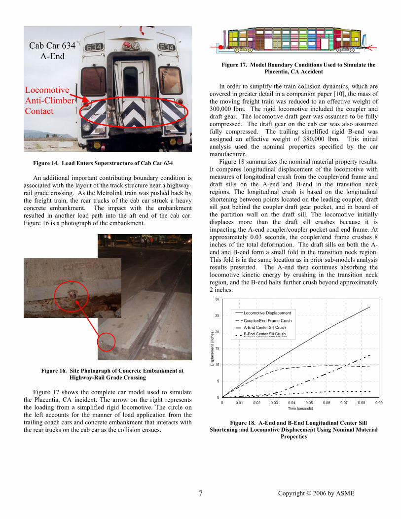
Figure 14. Load Enters Superstructure of Cab Car 634 An additional important contributing boundary condition is
associated with the layout of the track structure near a highway-rail grade crossing. As the Metrolink train was pushed back by the freight train, the rear trucks of the cab car struck a heavy concrete embankment. The impact with the embankment resulted in another load path into the aft end of the cab car. Figure 16 is a photograph of the embankment.
Figure 16. Site Photograph of Concrete Embankment at Highway-Rail Grade Crossing
Figure 17 shows the complete car model used to simulate
the Placentia, CA incident. The arrow on the right represents the loading from a simplified rigid locomotive. The circle on the left accounts for the manner of load application from the trailing coach cars and concrete embankment that interacts with the rear trucks on the cab car as the collision ensues.
Cab Car 634 A-End
Locomotive Anti-Climber Contact
7
Figure 17. Model Boundary Conditions Used to Simulate the Placentia, CA Accident
In order to simplify the train collision dynamics, which are
covered in greater detail in a companion paper [10], the mass of the moving freight train was reduced to an effective weight of 300,000 lbm. The rigid locomotive included the coupler and draft gear. The locomotive draft gear was assumed to be fully compressed. The draft gear on the cab car was also assumed fully compressed. The trailing simplified rigid B-end was assigned an effective weight of 380,000 lbm. This initial analysis used the nominal properties specified by the car manufacturer.
Figure 18 summarizes the nominal material property results. It compares longitudinal displacement of the locomotive with measures of longitudinal crush from the coupler/end frame and draft sills on the A-end and B-end in the transition neck regions. The longitudinal crush is based on the longitudinal shortening between points located on the leading coupler, draft sill just behind the coupler draft gear pocket, and in board of the partition wall on the draft sill. The locomotive initially displaces more than the draft sill crushes because it is impacting the A-end coupler/coupler pocket and end frame. At approximately 0.03 seconds, the coupler/end frame crushes 8 inches of the total deformation. The draft sills on both the A-end and B-end form a small fold in the transition neck region. This fold is in the same location as in prior sub-models analysis results presented. The A-end then continues absorbing the locomotive kinetic energy by crushing in the transition neck region, and the B-end halts further crush beyond approximately 2 inches.
0
5
10
15
20
25
30
0 0.01 0.02 0.03 0.04 0.05 0.06 0.07 0.08 0.09Time (seconds)
Disp
lace
men
t (in
ches
)
Locomotive Displacement
Coupler/End Frame Crush
A-end Center Sill Crush
B-end Center Sill Crush
Figure 18. A-End and B-End Longitudinal Center Sill Shortening and Locomotive Displacement Using Nominal Material
Properties
A-End Center Sill Crush B-End Center Sill Crush
7
Copyright © 2006 by ASME

The analysis condition with equal strength ends does clearly depict the formation of hinges that could cause crush on the A-end and B-end, but the majority of the crush is predicted on the A-end.
To further perturb the B-end in an attempt to recreate the deformation pattern observed in the accident, a second analysis condition is run reducing the material properties (stress-strain curve) of all the components on the B-end by 5 percent and increasing the material properties on the A-end by 5 percent. With all other parameters unchanged, several analyses were performed to determine how this strength change affects the force-crush curve and mode of deformation. While not presented here, results found that a 5 percent increase in the material strength shifts the force-crush curve up by approximately 2.5 percent, and the mode of deformation is unchanged. A decrease in material strength had the opposite effect with a similar magnitude change. Manufacturing (i.e., geometry and weld/bolt connections) and material property variation of the components in each end could realistically cause the ends to vary in strength from nominal.
Figure 19 presents the results for this analysis. Similar to the nominal case, the coupler/end frame crush accounts for the majority of the 10.5 inches of longitudinal displacement before 0.03 seconds. Subsequently, the A-end and B-end crush nearly equally until both reach a crush of approximately 10 inches. The A-end then stops, and the B-end continues to crush. The mode of crush on the A-end is a combination of a small amount of draft sill crush behind the coupler and larger amount of crush from a hinge in the transition neck region of the draft sill. The mode of crush on the B-end is the same as in the sub-models, driven by a hinge formation in the transition neck region of the draft sill.
0
5
10
15
20
25
30
35
40
0 0.02 0.04 0.06 0.08 0.1 0.12Time (seconds)
Disp
lace
men
t (in
ches
)
Locomotive Displacement
Coupler/End Frame Crush
A-end Center Sill Crush
B-end Center Sill Crush
Figure 19. A-End and B-End Longitudinal Center Sill Shortening and Locomotive Displacement Using 5 Percent
Strength Change to the Ends From the 5 percent variation analysis condition, the
formation of the majority crush hinge on the B-end does occur but not before the A-end is crushed approximately 10 inches.
A-End Center Sill Crush B-End Center Sill Crush
8
From the accident, a structural review of the A-end does show signs of permanent damage to the draft sill and side sills in similar locations to where the sub-model analysis predicts but not enough to crush 10 inches. To further perturb the B-end, a third analysis condition is run, reducing the material properties (stress-strain curve) of all the components on the B-end by 10 percent, and increasing the material properties on the A-end by 10 percent.
The trend of the prior analyses is maintained in the results presented in Figure 20. Again, the coupler/end frame accounts for the majority of crush before 0.03 seconds. The A-end and B-end crush nearly equally until both reach a crush of approximately 4 inches. The A-end crush stops, and the B-end continues to crush. The mode of crush on the A-end is only a small amount of draft sill crush from a hinge in the transition neck region. The mode of crush on the B-end is the same as in the sub-models, driven by a hinge formation in the transition neck region of the draft sill.
0
5
10
15
20
25
30
35
40
0 0.02 0.04 0.06 0.08 0.1 0.12Time (seconds)
Disp
lace
men
t (in
ches
)
Locomotive Displacement
Coupler/End Frame Crush
A-end Center Sill Crush
B-end Center Sill Crush
Figure 20. A-End and B-End Longitudinal Center Sill Shortening and Locomotive Displacement Using 10 Percent
Strength Change to the Ends To complete the discussion of the simulation of the
Placentia accident conditions, the deformation sequence is presented for the 10 percent strength change analysis in Figures 21 and 22. The results are very close to what was observed in the Placentia, CA accident in terms of the location where crush was focused. Some differences do exist. The degree of uneven lateral crush from left to right is much smaller in the prediction than what was observed in the accident. The torsional displacement is predicted to be much smaller from the left- and right-hand sides at the roof level.
Despite these differences, the model predictions have demonstrated that it is not entirely unreasonable to expect differential crush at either end of a vehicle of this design type under the correct loading conditions coupled with variability in the manufacturing process.
A-End Center Sill Crush B-End Center Sill Crush
8 Copyright © 2006 by ASME

Figure 21. Side and Top Views of Deformation Sequence for 10 Percent Strength Change to the Ends
Figure 22. Underframe Views of A-End and B-End Deformation Sequence for 10 Percent Strength Change to the
Ends Under nominal conditions crush is predicted in a similar
manner as expected from single level platform designs–crush is focused at the colliding interface. Additionally, from the post-accident investigation of the equipment involved in the Placentia, CA accident, the trailing coach car immediately behind the cab car experienced a small plastic hinge in the transition structure at the end closest to the cab car. Also experienced from the Glendale, CA accident, which involved similar car designs, crush was focused at forward-facing leading interfaces. These observations suggest that the conditions at the Placentia, CA accident were truly unusual.
9
SUMMARY & CONCLUSIONS
Structural response of a model of a multi-level cab car, typical of the one involved in the Placentia, CA collision, was investigated using non-linear large deformation crush analysis. This research was motivated by a collision in Placentia, CA, on April 23, 2002, where the deformation behavior contrasted the response of single level equipment in collisions.
The two hypotheses postulated to explain the deformation mode observed in the accident are that asymmetries in the carbody structure are present from side-to-side and/or front-to-back or that the loading condition that the carbody was subjected to was asymmetric. Results from the half models of the A-end and the B-end suggest that the asymmetries present do not result in significant differences in strength of the carbody left to right or from the lead to trailing end. The center section analysis results do support the assumption that crush will occur out board of the center section as it is stronger than either the A-end or the B-end. From the Placentia, CA accident condition analyses it is apparent that non-longitudinal/offset load applications, combined with differential carbody strength from front to back, can cause a similar deformation mode as observed in the accident. However, using nominal properties crush tends to be focused at the colliding interface.
The force-crush characteristics determined from these analyses have been used as input to several collision dynamic models used to study the Placentia, CA accident, as well as the Glendale, CA accident [10,11]. The car was designed to meet all current industry standards and Federal regulations. The design was developed using classical strength of materials structural design techniques as is typical of current car designs.
Intra-car telescoping deformation modes occur due to the significant change in load path resulting from accommodation of the low level boarding with quarter point doors. As crush ensues, a mechanism is formed in the transition structure of the car. Developing and using large deformation crush models to understand the modes of deformation that the carbody may experience when overloaded can be used to assure more graceful deformation modes in future designs.
More options for assuring graceful deformation may be possible if the requirement for buff strength along the line of draft is revisited. This requirement, reflected in industry
9 Copyright © 2006 by ASME

standards and Federal regulations, was developed to assure sufficient protection against intrusion into the occupied space of the car in the event of a collision or derailment. Such protection may be assured with allowances for limited plastic deformations and alternative loading conditions, if large deformation crush models and selected component tests are included as part of the carbody design development. Alternative occupant volume strength requirements could potentially permit more flexibility in designing low floor and articulated equipment. Further research is required to assure that any alternative means of specifying occupant volume strength is as effective as current requirements.
ACKNOWLEDGEMENTS This work was performed as part of the Equipment Safety
Research Program sponsored by FRA’s Office of Research and Development. The authors would like to thank Tom Tsai, Program Manager, and Claire Orth, Division Chief, Equipment and Operating Practices Research Division, Office of Research and Development, FRA, for their support.
The authors would also like to thank Jacques Brassard, Structure and Truck Engineering Department, Bombardier, for exchanging technical information and discussions pertaining to the post-collapse behavior multi-level car under large deformations. Bombardier provided a linear elastic model and drawings from which the multi-level car non-linear plastic model was constructed.
Hailing Yu, Mechanical Engineer, and Marisol Medri, Mechanical Engineer, Chenega Advanced Systems and Engineering, LLC, drafted the large deformation model of the multi-level car under a task order from the Volpe Center. References 1. Severson, K., Tyrell, D., Perlman, A.B., “Analysis of
Collision Safety Associated with Conventional and Crash Energy Management Cars Mixed Within a Consist,” American Society of Mechanical Engineers, Paper No. IMECE2003-44122, November 2003.
2. Priante, M., Tyrell, D., Perlman, A.B., “The Influence of Train Type, Car Weight, and Train Length on Passenger Train Crashworthiness,” American Society of Mechanical Engineers, Paper No. IMECE2005-70042, March 2005.
3. Jacobsen, K., Tyrell, D., Perlman, A.B., “Impact Tests of Crash Energy Management Passenger Rail Cars: Analysis and Structural Measurements,” American Society of Mechanical Engineers, Paper No. IMECE2004-61252, November 2004.
4 . Stringfellow, R., Rancatore, R., Llana, P., Mayville, R., “Analysis of Colliding Vehicle Interactions for the Passenger Rail Train-to-Train Impact Test,” American Society of Mechanical Engineers, Paper No. RTD2004-66037, April 2004.
5. Tyrell, D., “Passenger Rail Train-to-Train Impact Test Volume I: Overview and Selected Results,” U.S.
Department of Transportation, DOT/FRA/ORD-03/17.I, July 2003.
6. National Transportation Safety Board. 1982. Head On Collision of Boston & Maine Corp Extra 1731 East & MBTA Train No. 570 on Former Boston & Maine Corp. Tracks, Beverly, Massachusetts, August 11, 1981, Railroad Accident Report NTSB/RAR-82/01, Washington, DC.
7. National Transportation Safety Board. 2003. Collision of Burlington Northern Santa Fe Freight Train with Metrolink Passenger Train Placentia, California, April 23, 2002. Railroad Accident Report NTSB/RAR-03/04, Washington, DC.
8. Parent, D., Tyrell, D., Perlman, A.B., “Crashworthiness Analysis of the Placentia, CA Rail Collision,” Proceedings of ICrash 2004, International Crashworthiness Conference, San Francisco, California, July 14-16, 2004.
9. LSDYNA Version 970, Livermore Software Technology Corporation, Livermore, CA.
10. Priante, M., Tyrell, D., Perlman, A.B., “A Collision Dynamics Model of a Multi-Level Car,” American Society of Mechanical Engineers, Paper No. IMECE2006-13537, November 2006.
11. Federal Railroad Administration, 2006. “Report to the House and Senate Appropriations Committees: The Safety of Push-Pull and Multiple Unit Passenger Rail Operations,” Washington, DC.
1010 Copyright © 2006 by ASME