Embed Size (px)
Citation preview
CruisersOwner’s Manual
Model/Number: _____________________________________
Hull Identification Number:____________________________
Date of Purchase/First Use: __________________________
Dealer Name: _______________________________________
Address: ___________________________________________
___________________________________________
Phone Number: _____________________________________
WORLD CLASS BOATS ™
Catalog Requests Call 1-800-603-BOAT© 2000 Wellcraft Marine Corp., a subsidiary of Genmar Industries, Inc. 1651 Whitfield Avenue, Sarasota, FL 34243
For a complete list of standard and optional features and equipment, consult your local Wellcraft dealer. Due to a policy of continual product improvement, specifications are subjectto change without notice. The weights and volumes shown are estimated and can vary from boat to boat because of equipment, etc. Wellcraft boats meet or exceed U.S. Coast Guard
regulations at date of manufacture. Wellcraft is a trademark of Genmar Industries, Inc. Scarab is a registered trademark of Team Scarab, Inc.Printed in USA. Part No. 2601-2589
1

BOATS DESIGNED WITH NATURE IN MIND.As privileged visitors to the world’s oceans, lakes and waterways, we share anobligation to help protect our marine environment. Wellcraft is leading the waywith a variety of unique systems designed to help minimize the impact of recreational boating.
Congratulations on your new boat purchase andwelcome to our boating family!
We want your boating experience to be the mostenjoyable possible. The more you know aboutyour new boat, the more you’ll enjoy the timeyou spend aboard. That’s why we prepared thismanual. It’s your guide for safe operation aswell as understanding your boat’s systems andequipment. It has been written for the beginningboater but experienced boaters will find helpfulinformation as well. Be sure to read the con-tents thoroughly.
The popularity of boating and other water sportshas grown tremendously in the past few years.Because of this, safety is an important issuefor everyone who shares our waterways.
Remember that along with the freedom and exhil-aration of boating comes the responsibility thatyou have for the safety of your passengers andthe other boaters who share the water with you.Throughout this manual, specific precautions andsymbols identify safety-related information. Besure to pay close attention to them.
This symbol means “pay attention!” Hereis important information for your safety.If you don’t follow these instructions, youcan damage your boat, hurt yourself orsomeone else or, even worse, have afatal accident.
Due to our policy of continuous product improve-ment, the illustrations used in this manual maynot be identical to the components, controls,gauges, etc. on your boat, as they are intendedto be representative reference views. Some con-trols, indicators or information may be optionaland not included on your craft.
The precautions in this manual can’t and don’tcover ever y boating situation. If a specificmethod or procedure is not recommended, youmust make sure that what you do is safe foryou and others. Always use common sensewhen boating! Remember too that every safeboating excursion is a happy experience.
We’d also like to remind you to be kind to ourenvironment while you’re boating. Don’t throwgarbage and other refuse overboard. And doyour best to keep harmful compounds like gaso-line and antifreeze out of the water.
Introduction
!
This symbol and signal word indicate apotentially hazardous situation. If youignore this safety message, propertydamage or minor or moderate per-sonal injury MAY or CAN result.
CAUTION!
This symbol and signal word indicate apotential hazard. If you ignore thissafety message, serious injury ordeath CAN result.
WARNING!
This symbol and signal word indicatean immediate hazard. If you ignore thissafety message, serious personalinjury or death WILL result.
DANGER!
This manual has been compiled to help you operate your craft with safety and pleasure. It contains thedetails of the craft, the equipment supplied or fitted, its systems, and information on its operation andmaintenance. Please read it carefully and familiarize yourself with the craft before using it.
If this is your first craft, or if you are changing to a type of craft you are not familiar with, for your owncomfort and safety, please ensure that you obtain handling and operating experience before “assum-ing command” of the craft. Your dealer or national sailing federation or yacht club will be pleased toadvise you of local sea schools and competent instructors.
PLEASE KEEP THIS MANUAL IN A SECURE PLACE, AND HAND IT OVER TO THE NEW OWNER WHENYOU SELL THE CRAFT.
IntroductionTable of ContentsGeneral Information .............................1-1
YOU AND YOUR NEW BOAT....................1-2BOATING LAWS AND REGULATIONS........1-6RECOMMENDED READING.....................1-8SERVICE MAINTENANCE LOG...............1-11BOAT DATA SHEET ..............................1-12FUEL LOG...........................................1-13FLOAT PLAN .......................................1-14WARRANTY REGISTRATION TRANSFER..1-15
Boating Safety ....................................2-1ADVISORY STATEMENTS........................2-1HAZARD COMMUNICATION ....................2-1SAFE BOATING RECOMMENDATIONS ......2-1SAFETY EQUIPMENT..............................2-2SAFE BOATING COURSES ......................2-5DRUGS AND ALCOHOL ..........................2-5SAFE OPERATION..................................2-5CARBON MONOXIDE .............................2-7CARBON MONOXIDE ACCUMULATION .....2-8WATER SPORTS ....................................2-9RULES OF THE ROAD ..........................2-10GENERAL RULES OF SEAMANSHIP .......2-12NAVIGATIONAL AIDS CHART .................2-15
Specifications and Layout ....................3-1SPECIFICATIONS...................................3-8SAFETY LABEL LOCATIONS ....................3-9
Water Systems....................................4-1FRESH WATER SYSTEM.........................4-1WATER SYSTEM TROUBLESHOOTING .....4-4RAW WATER SYSTEM ............................4-4SEACOCKS...........................................4-4WASTE SYSTEM....................................4-5BILGE SYSTEM.....................................4-6WASTE SYSTEM TROUBLESHOOTING .....4-6
Fuel System ........................................5-1FUEL SYSTEM COMPONENTS ................5-1FUEL SYSTEM TROUBLESHOOTING ........5-2
Electrical Systems...............................6-1WIRING COLOR CODE ...........................6-112-VOLT DC ELECTRICAL SYSTEM..........6-1AC ELECTRICAL SYSTEM .......................6-4MAIN ELECTRICAL PANEL ......................6-6
Electrical Systems Cont. .....................6-1GALVANIC CORROSION..........................6-8BONDING .............................................6-9TROUBLESHOOTING CHART.................6-10
Boat Equipment...................................7-1STOVE .................................................7-1REFRIGERATOR.....................................7-1OVEN...................................................7-1COFFEE MAKER ....................................7-1MARINE STEREO...................................7-1AIR CONDITIONING SYSTEM ..................7-2AUTOMATIC FIRE SUPPRESSION
SYSTEM .........................................7-3TV/VCR (OPTIONAL) ..............................7-3VHF RADIO ...........................................7-3
Underwater Gear .................................8-1PROPELLERS........................................8-1PROPELLER SHAFT ...............................8-1STRUTS ...............................................8-1SHAFT LOG AND STUFFING BOX.............8-1RUDDERS ............................................8-2TRIM TABS ...........................................8-2TROUBLESHOOTING CHART...................8-2
Controls and Indicators........................9-1INSTRUMENTATION ...............................9-1STEERING ............................................9-2STERN DRIVE THROTTLE/
SHIFT CONTROLS............................9-3INBOARD ENGINE AND
TRANSMISSION CONTROLS .............9-4
Pre-launch and Underway...................10-1LAUNCH AND CRUISE CHECKLIST........10-1FUELING ............................................10-2LOADING PASSENGERS AND GEAR.......10-3STARTING PROCEDURES .....................10-4MANEUVERING ...................................10-5ACCELERATION...................................10-5TRIMMING YOUR BOAT........................10-6EXCESSIVE NOISE ..............................10-8ANCHORING .......................................10-8NAVIGATION LIGHTS............................10-9HAZARDOUS CONDITIONS...................10-9REACTING TO EMERGENCIES.............10-11ADDITIONAL UNDERWAY INFO............10-13RETURNING TO SHORE .....................10-13
Table of Contents

Winterization and Commissioning.......11-1LIFTING THE BOAT ..............................11-1ENGINE, SYSTEMS & COMPONENTS ....11-2STORAGE ON TRAILER ........................11-5RECOMMISSIONING THE
BOAT AFTER STORAGE...................11-5
General Maintenance.........................12-1SERVICE SCHEDULE ...........................12-1SALTWATER CORROSION .....................12-2BOTTOM MAINTENANCE ......................12-2PROTECTION AGAINST ELECTROLYSIS..12-3DECK AND HULL CARE........................12-3FIBERGLASS REPAIR ...........................12-4HARDWARE AND FITTINGS...................12-5UPHOLSTERY .....................................12-5INTERIOR FABRICS..............................12-6WINDSHIELDS AND WINDOWS.............12-6CARPETING ........................................12-6CANVAS .............................................12-6
Trailering...........................................13-1GROSS VEHICLE WEIGHT RATING.........13-1WEIGHT DISTRIBUTION .......................13-1HITCH................................................13-1SAFETY CHAINS..................................13-2TRAILERING GUIDELINES.....................13-2BACKING A TRAILER............................13-3LAUNCHING GUIDELINES.....................13-3LOADING YOUR BOAT
ON THE TRAILER ...........................13-4
Nautical Glossary ..............................14-1
TC-2
This manual has been compiled to help you tooperate your boat with safety and pleasure. Itcontains details of the vessel, the equipmentsupplied or fitted, its systems and informationon its operation and maintenance. Please readit carefully, and familiarize yourself with the boatbefore using it.
If this is your first boat or if you are changing toa type of boat you are not familiar with, for yourown comfort and safety, please ensure that youobtain handling and operation experience before“assuming command” of the boat. Your dealer,or U.S. Coast Guard Auxiliary or yacht club willbe pleased to advise you of local sea schools,or competent instructors.
1-1
General Information – 1
DRAFT DRIVESDOWN
HELM
STARBOARDSIDE
PORTSIDE
BE
AM
LENGTH OVERALL (LOA)
TRANSOM
STERNDRIVE
PROPELLER
STERN
FREEBOARD
DRAFT
GUNWALE
BOW
WATERLINE
AFT FORWARD
KEEL
BRIDGECLEARANCE
SHAFT
PROPELLERSTRUT
RUDDER
STERNDRIVE POWER
INBOARD POWER
STERN
FREEBOARD
GUNWALE
BOW
WATERLINE
AFT FORWARD
KEEL
BRIDGECLEARANCE
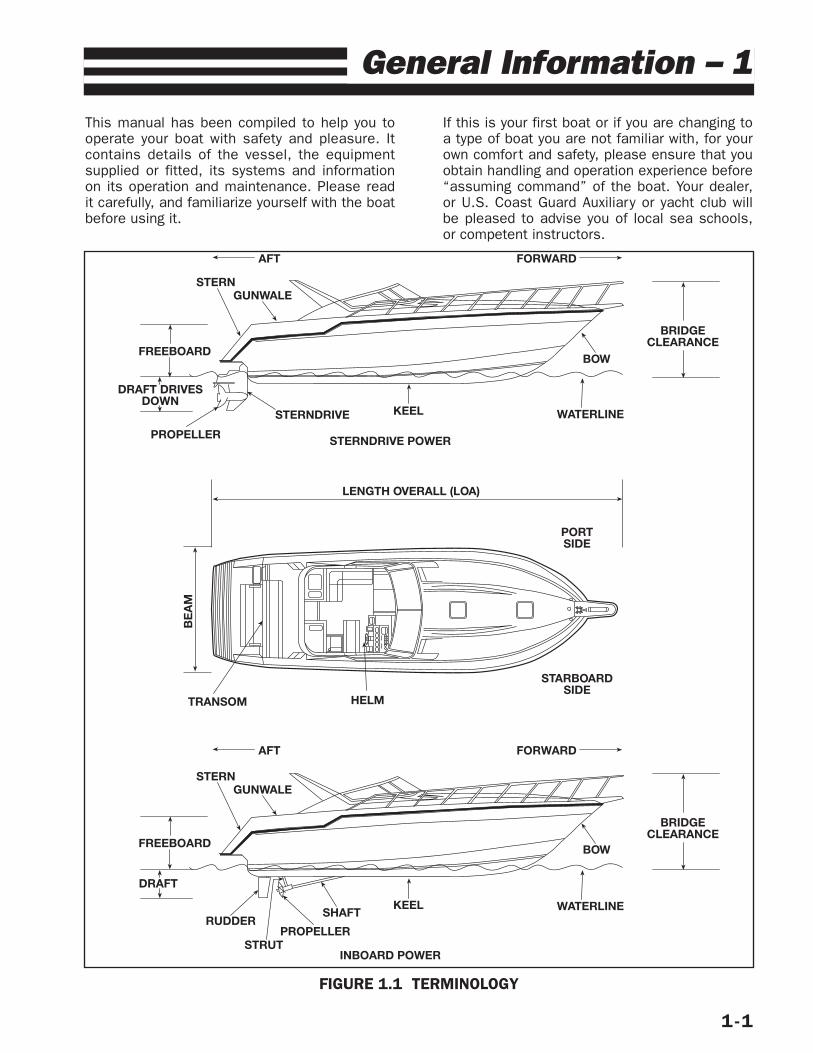
FIGURE 1.1 TERMINOLOGY
YOU AND YOUR NEW BOAT
Congratulations on your new boat and welcometo the Wellcraft family. We want you to receivethe most enjoyment possible from your newboat, and the more you know about it, the eas-ier that will be.
It is important that you take the time to readthis entire manual prior to taking your boat outfor the first time. Also read all literature sup-plied with your boat by the manufacturers of thevarious components and accessories which areused on your boat. In particular, you want tobecome familiar with operating your engine. Thisowner’s manual does not supersede or changeany of the original manufacturers’ specifica-tions, operation or maintenance instructions.
If you are new to boating, you may not be famil-iar with some common boating terms. Figure1.1 lists some of these terms and identifiestheir meaning in relation to a typical boat.
Review and train yourself and your family in safety,emergency and operating procedures. Pay closeattention to all highlighted safety warnings, cau-tions and hazards, and remember that along withthe freedom and fun of a powerboat, comes theresponsibility for the safety of your passengers,other boaters and the environment which we allshare. We recommend that you read the boatingliterature published by your state boating agencyand the U.S. Coast Guard. Other suggested read-ing can be found later in this section.
Also, take the time to know your boat. Look itover, walk around in it, locate the different com-ponents, gauges, and operating equipment andfigure out how to use them before you go out onthe water. This familiarity allows for a muchsafer and smoother boating experience.
CONSTRUCTION STANDARDS/CERTIFICATIONAll our boats meet or exceed the constructionstandards set by the U.S. Coast Guard and theAmerican Boat and Yacht Council (ABYC) con-cerning:
• Navigational lights• Factory installed fuel systems• Engine and fuel tank compartment
ventilation• Flotation• Steering systems• Backfire flame arresters
Most Wellcraft models have also been certifiedto carry the CE mark. The CE mark certifies thatthe boat meets relevant parts of the EuropeanDirective for Recreational Craft 94/25/EC of the
1-2
European Parliament, including the InternationalOrganization for Standards (ISO) and Recre-ational Marine Agreement Group (RMAG)guidelines in effect at the time of manufacture.
We recommend that you see your dealer if youwish to modify factory–installed equipment oradd new equipment. Your dealer is qualified tomake such modifications or additions withoutplacing the safety or design integrity of your boatat risk and without invalidating the warranty.
RESPONSIBILITIES
Boat Owner
1. Sign the warranty registration card includingyour address and the boat and hull serialnumbers and mail it to us.
2. Inspect the boat at the time of delivery toverify that all systems and components areoperating safely and acceptably. Read allmanuals and instructions.
3. Operate all equipment in compliance withthe manufacturer’s instructions.
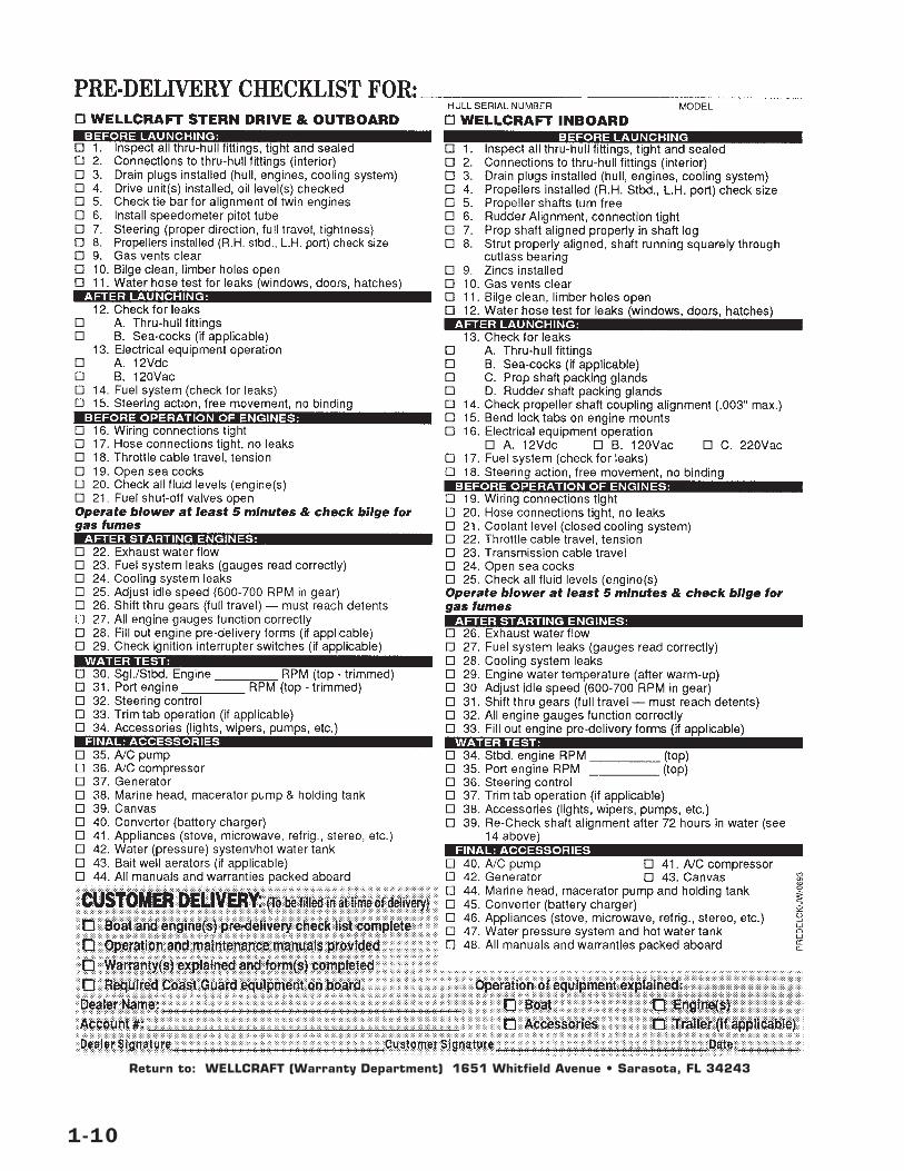
4. Review the pre-deliver y checklist for theboat and engine with your dealer when youtake delivery.
5. Schedule your 20-hour boat and enginecheckup with your dealer.
6. Know your boat and the rules of the roadbefore you use your boat.
IMPORTANT: Make sure that your dealer checksthe engine alignment during your boat’s 20-hourcheckup. The engine alignment check should beperformed in accordance with the recommendedprocedures as stated by the engine manufac-turer in your engine owner’s manual. Failure todo so could result in drive train damage which isnot covered under the warranty.
7. We recommend that you reference yourengine warranty certificate for initial inspec-tion and service requirements.
8. Perform or provide for the scheduled main-tenance checks outlined in this manual andall related service guides and manuals.
Along with boating, comes responsibility.Responsibility for safety, boating laws, and the
environment. Please think about the future ofour waterways, oceans and marine life whileyou’re out enjoying them and take all neces-sar y measures to help protect what naturalhabitats we have left. Keeping our waterwaysand marine habitats free from debris, andshowing consideration for the creatures whothrive in these environments are some waysyou can help assure the pleasure of boating foryears to come.
The operator is also responsible for complyingwith the following procedures and operationalrequirements:
• State registration• Insurance• Warranty registration• Warranty terms and conditions• Rules of the road• Break-in procedure• Proper maintenance of the boat and its sys-
tems• Safety equipment• Safety training of passengers and crew• Knowledge of boat systems• Seaworthiness/operational inspection• Safe operating practices• Avoiding use of drugs/alcohol• Environmental regulations• Accident reports
Dealer
Your dealer will complete the pre-delivery check-list with you when you take deliver y of yourboat. A copy of the checklist is at the end ofthis section. Your dealer will also provide the fol-lowing services:
1. Sign the checklist to certify that your boat isin top-notch condition and that all compo-nents are working properly.
2. Discuss the terms of all warranties andemphasize the impor tance of registeringeach warranty with the manufacturer.
3. Explain the proper procedures for obtainingwarranty service.
4. If requested, provide you with comprehensiveinstruction in the operation of your boat andall its installed systems and components.
1-3
WARRANTYThe Limited Warranty, in its entirety, appears onthe warranty registration card and is included atthe end of this chapter. We have made everyeffort to simplify our warranty so that it may beeasily understood. However, if you have anyquestions regarding the warranty please don’thesitate to contact us.
Wellcraft Marine Corp.Attn: Customer Service1651 Whitfield AvenueSarasota, FL 34243
Phone: (941) 753-7811
NOTE: There are items which are not coveredby this warranty, including:
• Incidental and consequential damages (stor-age charges, telephone or rental charges ofany type, inconvenience or loss of time orincome.)
• Damage caused by neglect, lack of mainte-nance, accident, abnormal operation,improper installation or service.
• Haul-out, launch and towing charges.
• Transportation charges and/or travel time toand from a repair facility.
• Travel time to customer’s home or marina.
• Service requested by customer other thanthat necessary to satisfy the warranty obli-gation.
• Oils, lubricants or fluids used in normalmaintenance.
• Air freight, next-day or second-day air, or anyspecial delivery fees unless pre-approved.
• Gelcoat cracking, yellowing, crazing or blis-tering, plexiglas, canvas, vinyl or tapeunless noted on equipment check off list attime of delivery.
• Engines, drive trains, controls, props, batter-ies, or other equipment or accessoriescarrying their own individual warranties.
• It is important to note that on many of thecomponents in our boats, i.e. stoves, refrig-erators, generators, trim tabs, etc., thewarranties are extended by the component
manufacturer. (Most component manufactur-ers repair or replace the defectivecomponent if it is returned to them.) Thecustomer is responsible for all travel time,freight, or postage costs. We will pay for thecost to remove and replace the component.
• Engines, parts or accessories not installedby Wellcraft Marine Corp.
• Plexiglas windscreen breakage, rainwaterleakage through convertible tops, minor gel-coat discoloration, cracks, crazing, or airvoids.
• Windshield and canvas top leakage: A cer-tain amount of leakage can occur at thefasteners and at the stitching.
• Minor gelcoat discoloration or chalking mayoccur if regular washing and waxing hasbeen neglected. Proper care of the gelcoatfinish is the responsibility of the owner.
• Hull blisters that form below the waterline:Osmosis blistering is not covered by our lim-ited warranty. The phenomenon is mostlikely to occur in warm, fresh water. How-ever, it can also occur in saltwater. Any boatleft in the water for any period of time issusceptible. Nearly all the marine bottompaint manufacturers today of fer coatingsthat help protect the hull against osmosisblistering. We highly recommend that youadd a protective coating to your hull.
• Normal deterioration, i.e. wear, tear, or cor-rosion of hardware, vinyl tops, vinyl andfabric upholstery, plastic, metal, wood, ortrim tape.
• Hardware: Metal hardware that has rustedor pitted will not be replaced under warranty.You should keep this hardware clean andwiped down with a light oil (WD40).
• Vinyl tops: Wellcraft does not warrant dam-age that might occur when a boat is beingtowed on a trailer with the top up, and doesnot warrant shrinkage, mildew, or other nor-mal deterioration.
• Any boat used for commercial purposes:This includes boats used for char ter pur-poses or time-share.
• Any defect caused by failure of the customerto provide reasonable care and maintenance.
1-4
By signing the warranty registration card you,the new owner, indicate an understanding of theterms and conditions of the Limited Warranty.The warranty registration card should be prop-erly completed by the dealer, signed by the newowner, and returned to us within fifteen (15)days after the original purchase in order to vali-date the warranty. Be sure to keep the Owner’sRegistration Card for your records.
All boat manufacturers are required by The Fed-eral Boat Safety Act of 1971 to notify first timeowners in the event any defect is discovered“which creates a substantial risk of personalinjury to the public.” In order for us to complywith that law, if it becomes necessar y, it isessential that your warranty registration cardwith the owner’s name, address, and boatserial number be completed and mailed to Well-craft Marine, 1651 Whitfield Ave., Sarasota,Florida 34243.
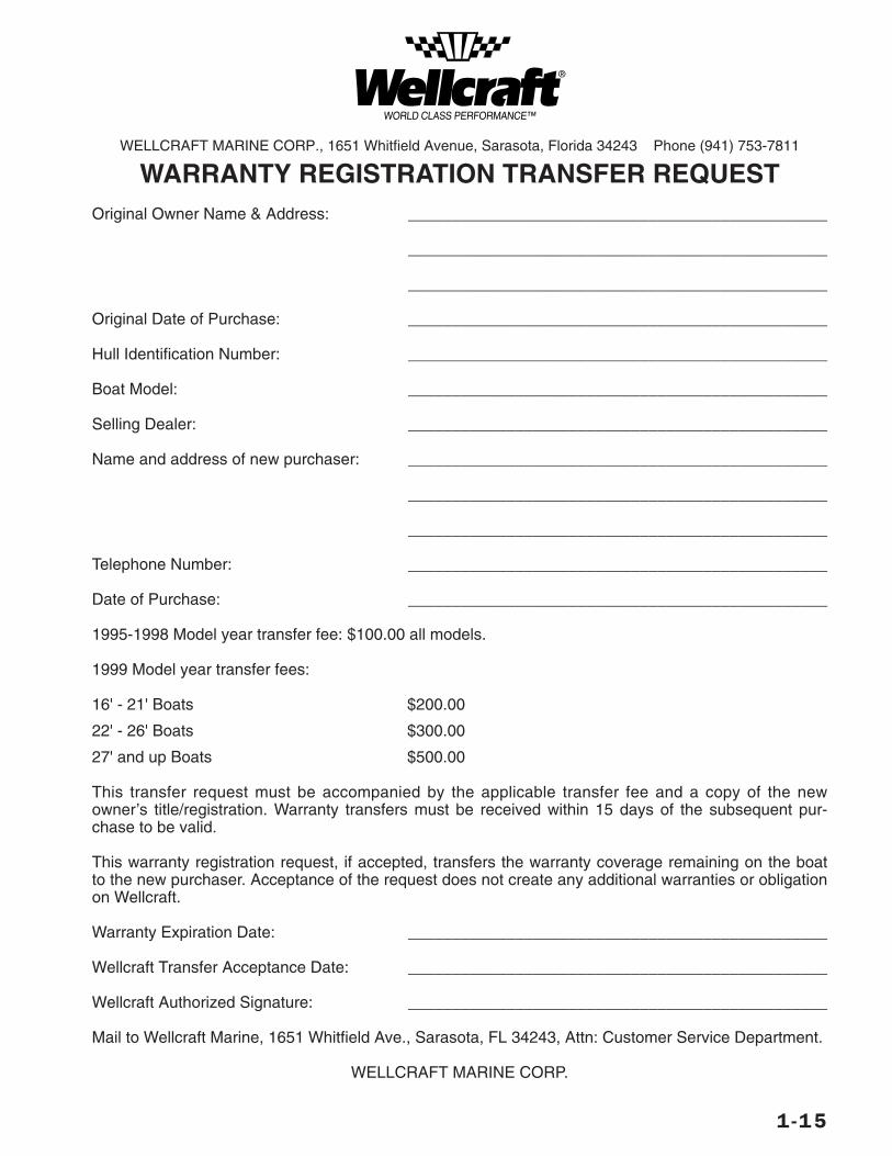
The limited warranty for your boat is transferableand can be extended to the next purchaser forthe remainder of the warranty period by notifyingWellcraft Marine in writing within 15 days of thetransfer, by using the warranty registration trans-fer form found at the end of this chapter. Thetransfer request must be accompanied by a copyof the title/registration and the transfer fee asdetermined by the boat length overall:
BOAT LENGTH OVERALL TRANSFER FEEUp to 21' $200.00Over 21' to 26' $300.00Over 26' $500.00
WARRANTY SERVICEAs the owner, you are responsible for the properregistration of your boat at the time of pur-chase. You must also follow proper operationprocedures and adhere to the care and mainte-nance procedures set forth in this manual. Besure to read your boat’s warranty, as well as theinformation and warranties (provided in yourowner’s portfolio) for major components. Youare responsible for notifying your dealer in writ-ing of any claimed defect within a reasonableperiod of time and returning your boat to yourdealer for service.
Your dealer has been carefully selected toassist you with your sales and service needs.Your dealer will be glad to answer any of yourquestions about your new boat. The dealer hasa direct interest in you as a customer andwants to see that you are completely satisfied
with your purchase. The dealer is in the bestposition to help you and has full support andassistance from Wellcraft Marine.
If, for any reason, you are dissatisfied with theservices performed by your dealer, we suggestthat you discuss the matter with the servicemanager. The service manager is responsible forthe quality of service being performed and has adirect interest in your satisfaction. If the matteris complicated and cannot be resolved to yoursatisfaction by the service manager, we suggestthat you talk to the general manager or owner. Inmost cases a compromise can be reached.
If the matter cannot be resolved by the dealer-ship to your satisfaction, contact the WellcraftMarine Customer Service Department by calling(941) 753-7811 or by writing to:
Wellcraft Marine Corp.Customer Service Department
1651 Whitfield AvenueSarasota, FL 34243
Have the following information available:
• HIN (hull identification number)• Selling dealer’s name and location• Date of purchase• Servicing dealer (if dif ferent from selling
dealer)• Nature of problem• Names of dealership personnel involved
with the situation• Record of service per formed and approxi-
mate dates
When contacting Wellcraft Marine, keep inmind that your problem will most likely beresolved at the dealership, using the dealer-ship’s facilities, equipment, and personnel.
OWNER’S PORTFOLIOSome manufacturers of components such asthe engine and AM/FM stereo cassette supplytheir own instruction manuals which areincluded in your water-resistant “Owner’s Portfo-l io.” The information in the componentinstruction manuals may be different from theinformation in this manual because of productimprovements. If you notice a discrepancy,ALWAYS FOLLOW THE INSTRUCTIONS IN THESUPPLIER'S MANUAL. Additionally, the suppliersof these products maintain their own manufac-turer’s warranty and ser vice facilities. Toregister your ownership, fill out and mail each
1-5
warranty card. Use your Owner’s Por tfolio toretain instructions and data on additional equip-ment or accessories installed after delivery.
IMPORTANT: Operation, maintenance andsafety information is outlined by the manufac-turer of most installed equipment. Properlyoperating and maintaining the equipment onyour boat will help you to enjoy many years ofSAFE boating.
OWNER’S LOGS AND RECORDSAt the end of this section are several formswhich you will find very helpful.
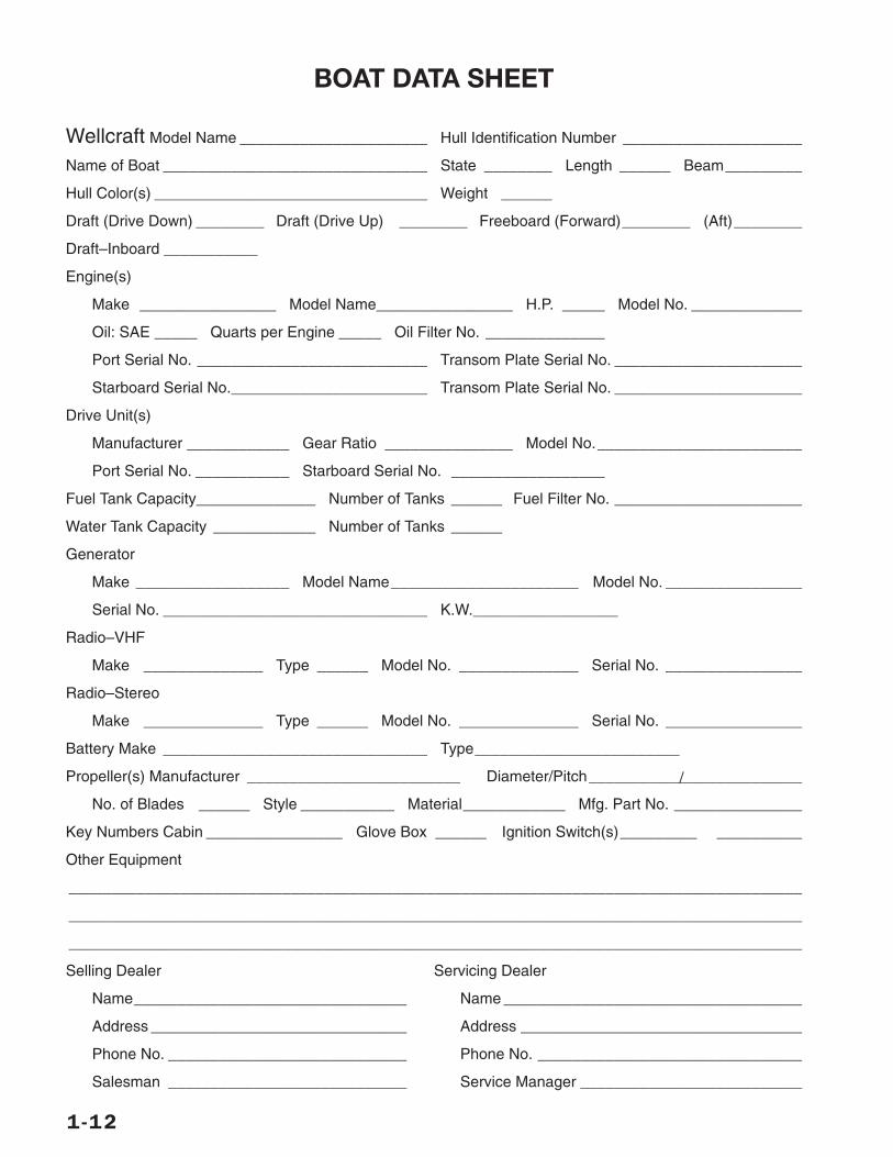
Use the Boat Data Record to record all impor-tant information about your boats and the majorcomponents installed. After you have entered allthe data, remove this form from your Owner’sManual and store in a safe place. Do not keepthis form aboard your boat.
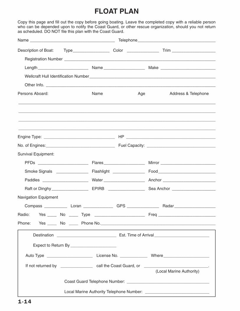
The Float Plan provides a record of your desti-nation, depar ture and return times, boatdescription, passenger list, and other informa-tion about the trip you have planned. At thebottom of the form is space for listing emer-gency telephone numbers in case your return isdelayed past the expected time. It also hasspace for indicating information about the per-son filing this report. Leave the completed formashore with a responsible person. We recom-mend you make several copies of this form eachboating season to assure an ample supply.
The Fuel Log is a handy way to record informa-tion covering engine hours, fuel on board, andrange as well as engine speed, travel speedand fuel consumption.
The Service/Maintenance Log provides arecord of maintenance work completed on yourboat, the date of completion and the enginehour reading. This log will also help you identifythe frequency of routine maintenance work,such as engine oil changes. If you shoulddecide to sell your boat, it will demonstrate toprospective buyers that you have done a goodjob of taking care of your boat.
BOATING LAWS AND REGULATIONS
The U.S. Coast Guard is the authority of thewaterways; they are there to help the boatingpublic. State boating regulations are enforcedby local authorities. You are subject to marinetraffic laws and “Rules of the Road” for bothfederal and state waterways; you must stop ifsignaled to do so by enforcement officers, andpermit to be boarded if asked.
There are many pamphlets, prepared by theCoast Guard, available to you. These pamphletsexplain “Rules of the Road,” signal lights,buoys, safety, international and inland regula-tions and other information which goes beyondthe scope of this manual. For more informationcontact your local U.S. Coast Guard Unit or callthe Coast Guard Boating Safety Hotline at 1-800-368-5647.
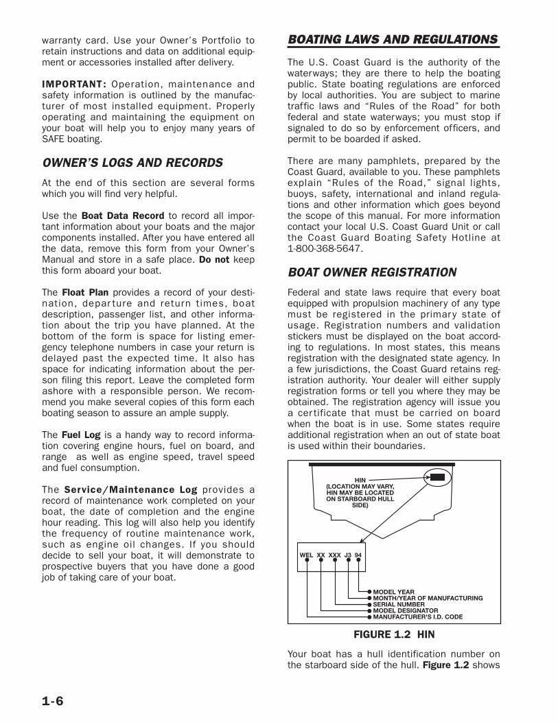
BOAT OWNER REGISTRATIONFederal and state laws require that every boatequipped with propulsion machinery of any typemust be registered in the primar y state ofusage. Registration numbers and validationstickers must be displayed on the boat accord-ing to regulations. In most states, this meansregistration with the designated state agency. Ina few jurisdictions, the Coast Guard retains reg-istration authority. Your dealer will either supplyregistration forms or tell you where they may beobtained. The registration agency will issue youa cer tificate that must be carried on boardwhen the boat is in use. Some states requireadditional registration when an out of state boatis used within their boundaries.
Your boat has a hull identification number onthe starboard side of the hull. Figure 1.2 shows
1-6
HIN(LOCATION MAY VARY,HIN MAY BE LOCATEDON STARBOARD HULL
SIDE)
WEL XX XXX J3 94
MODEL YEARMONTH/YEAR OF MANUFACTURINGSERIAL NUMBERMODEL DESIGNATORMANUFACTURER'S I.D. CODE
FIGURE 1.2 HIN
a typical identification number. Use this hullidentification number for registration and toidentify your boat for warranty service.
INSURANCEIn most states, the boat owner is legally respon-sible for damages or injuries he or she causes,even if someone else is operating the boat atthe time of the accident. Common sense dic-tates that you carry adequate personal liabilityand property damage insurance on your boat,just as you would on an automobile. You shouldalso protect your investment by insuring yourboat against physical damage or theft.
ACCIDENT REPORTINGThe operator of the boat is responsible for filinga report with the appropriate authorities. In gen-eral, repor ts are necessar y for accidentsinvolving loss of life, injur y, or damage over$500. In the case of accidents with reportableinjuries or death, a formal repor t is requiredwithin 48 hours. If only proper ty damage isinvolved, a repor t must be made within tendays. The 1994 Recreational Boating Act mayimpose a $1,000 civil fine for people who fail tosubmit a boating accident repor t. Ask yourinsurance agent for more information.
If you see a distress signal, you must assume itis a real emergency and render assistanceimmediately. The master or person in charge ofa boat is obligated by law to provide assistanceto any individual in danger at sea. However, youshould not put your boat or crew in a dangeroussituation which exceeds your capabilities orthose of your boat. The 1971 Boating Safety Actgrants protection to a Good Samaritan boateroffering good faith assistance, and absolves aboater from any civil liability arising from assis-tance given.
DISCHARGE OF OILThe Federal Water Pollution Control Act prohibitsthe discharge of oil or oily waste into or uponthe navigable waters of the United States or thewaters of the contiguous zone if such dischargecauses a film or sheen upon or a discolorationof the surface of the water or causes a sludgeor emulsion beneath the surface of the water.Violators are subject to a penalty of $5,000.
DISPOSAL OF PLASTICS & OTHER GARBAGEPlastic refuse dumped in the water can kill fishand marine wildlife and can foul boat propellersand cooling water intakes. Other forms of water-borne garbage can litter our beaches and makepeople sick. U.S. Coast Guard regulations pro-hibit the dumping of plastic refuse or othergarbage mixed with plastic into the water any-where, and restrict the dumping of other formsof garbage within specified distances fromshore.
MARPOL TREATYBoats 26 feet or longer must display a sign stat-ing the disposal regulations of the FederalWater Pollution Control Act. The U.S. CoastGuard has issued these regulations to imple-ment Annex V of the International Conventionfor the Prevention of Pollution from Ships,1973, commonly known as Annex V of the MAR-POL (Marine Pollution) Treaty 73/78. They applyto all U.S. boats wherever they operate (exceptwaters under the exclusive jurisdiction of aState) and foreign boats operating in U.S.waters out to and including the Exclusive Eco-nomic Zone (200 miles). It is important to knowthese regulations and adhere to them.
The regulations require U.S. recreationalboaters, if your boat is 26 feet or more inlength, to affix one or more USCG Trash Dump-ing Restrictions placards to your boat. Theplacard warns against the discharge of plasticand other forms of garbage within the navigablewaters of the United States and specify dis-charge restrictions beyond the territorial sea.(The territorial sea generally ends three nauticalmiles from the seashore.) In addition, the plac-ard must contain the warning that a person whoviolates these requirements is liable to civil($25,000) and criminal (imprisonment) penal-ties. The placard also must note that State andlocal regulations may fur ther restrict the dis-posal of garbage.
Operators shall display one or more placards ina prominent location and in sufficient numbersso they can be observed and read by crew andpassengers. These locations might includeembarkation points, food service areas, galleys,garbage handling spaces and common deckspaces frequented by crew and passengers. Werecommend that these placards be installed onall boats. The placards may be purchased from
1-7
local marinas, boat dealerships and marineequipment suppliers. A special placard is avail-able for boats operating on the Great Lakes.
IMPORTANT: It is illegal to discharge wastefrom your marine sanitary device (toilet) into thewater in most areas. It is your responsibility tobe aware of and adhere to all local laws con-cerning waste discharge. Consult with the CoastGuard, local marina or your dealer for additionalinformation.
NOTE: Some states and localities have legallimits on speed, noise and trailer specifications.It is your responsibility to be aware of theselaws and limits and to insure that your boat(and trailer) comply. Consult with your localMarine Patrol or local Coast Guard office.
RECOMMENDED READING
Damford, Don. Anchoring. (ISBN 0-915160-64-1). Seven Seas.
United States Coast Guard Auxiliary. BoatingSkills and Seamanship. LC74-164688. (illus.).(ISBN 0-930028-00-7). U.S. Coast Guard.
Bottomley, Tom. Boatman’s Handbook, (illus.).316 p. pap. (ISBN 0-688-03925-1, HearstMarine Bk.). Morrow.
Whiting, John and Bottomley, Tom. Chapman’sLog and Owner’s Manual. 192 p. (ISBN 0-87851-801-0); (ISBN 0-686-96737-2). Hearst Bks.
Strahm, Virgil. Does Your Fiberglass Boat NeedRepair? LC81-90093. (illus.). 46 p. pap (ISBN0-9606050-0-2). Strahm.
Chapman, Charles F. and Maloney. E.S. Chap-man’s Piloting, Seamanship and Small BoatHandling. (illus.) 62 p. (ISBN 0-87851-814-2,Pub. by Hearst Bks.); deluxe ed. (ISBN 0-87851-815-0). Morrow
National Fire Protection Association. Fire Protec-tion Standard for Pleasure and CommercialMotor Craft. (ISBN 0-317-07388-5, NFPA 302).Natl. Fire Prot.
Brother ton, Miner. Twelve-Volt Bible. Plasticcomb. (ISBN 0-915160-81-1). Seven Seas.
CONTACTSEducation programs are sponsored by publica-tions and organizations such as the U.S. PowerSquadron, U.S. Coast Guard Auxiliary and TheAmerican Red Cross. See your dealer aboutspecial courses available in your area. Fordetailed information contact:
American Red Cross (For local address consultthe telephone directory).
Boat U.S. Foundation for Boating Safety Hotline1-800-336-BOAT1-800-245-BOAT (in Virginia)Coast Guard Boating Safety Hotline1-800-368-5647
Skippers CourseGPO Superintendent of DocumentsWashington, DC 20012
United States Coast Guard AuxiliaryLocal Flotilla or contact appropriate Coast GuardDistrict Headquarters
United States Coast Guard Headquarters202-512-1800202-512-2250 (fax)
United States Power SquadronP.O. Box 30423Raleigh, NC 27617
1-8
1-9
Wellcraft Marine Corporation (“Wellcraft”), warrants to you, the firstretail purchaser of this 2001 model year or later boat, that it willrepair or replace defects in materials or workmanship that occurwithin the applicable warranty periods, subject to limitations setforth below. The applicable Warranty Period runs from the date theboat is delivered:
Defects in non-structural parts and components: One (1) year War-ranty Period.
Defects in structural parts and components: Five (5) year WarrantyPeriod.
Your sole and exclusive remedy is the repair or replacement, atWellcraft’s sole option, of parts and components covered by thiswarranty.
This Wellcraft boat, including any alleged defective part, must bereturned to an authorized Wellcraft dealer within the applicable war-ranty period to obtain warranty service. The Wellcraft dealer willcarry out the warranty procedures on the owner’s behalf. All war-ranty work will be performed at an authorized dealer, at the Wellcraftfactory, or at another repair facility that Wellcraft selects. The owneris responsible for the expense associated with transporting the boatto and from the repair facility.
An action for breach of warranty shall be barred unless it is com-menced within four (4) years from the date the cause of actionaccrues. An action for breach of any duty or obligation to repair orreplace shall be barred unless it is commenced within one year fromthe date the cause of action accrues regardless of the time remain-ing in the Warranty Period.
WHAT THIS WARRANTY DOES NOT COVER
A boat purchased from any party other than an authorized Wellcraftdealer.
A boat, including its components, that has been altered or modifiedso as to adversely affect its operation, performance or durability.
Engines, outdrives, controls, propellers, batteries, appliances andother equipment or accessories which are not manufactured byWellcraft, whether or not warranted by other manufacturers.
Gelcoat finishes (including blistering and osmotic blistering, crack-ing, crazing or discoloration), mirrors, window glass, varnishes,paints, fabrics, chromium plated and stainless steel finishes,because of the varying effects resulting from different climatic anduse conditions.
The cost of removal or re-instatement of parts or disassembly ofunits to repair or replace components covered by this warranty.
Any boat which has been misused, used in a negligent manner,used for racing, used for rental, charter, military or other commer-cial purposes, used without normal maintenance, operated contraryto any instruction furnished by Wellcraft, or operated in violation ofany Federal, State, Coast Guard or other governmental agency laws,rules or regulations.
Any representation relating to speed, range, fuel consumption orother estimated performance characteristic.
Loss of time, inconvenience, boat payments, retail charges,improper lifting or trailering, travel expense, loss of use, in-and-out-of-water charges, towing and storage charges, loss of or damage topersonal property, or other remedies not specifically allowed.
Dealer preparation, cleaning, final adjustments and alignments inpreparing the boat for delivery or commissioning.
Leakage around windshield, hatches or other designed openings.
Fit and adjustment of exterior canvas tops, enclosures, and weathercovers.
Sacrificial deterioration of anti-fouling paint or zinc anodes.
Remedy under this warranty is expressly limited to repair or replace-ment of defects in materials or workmanship, and does not includeincidental or consequential damages which are specifically DIS-CLAIMED. Note: SOME STATES DO NOT ALLOW THE EXCLUSION ORLIMITATION OF INCIDENTAL OR CONSEQUENTIAL DAMAGES, SO THEABOVE LIMITATION OR EXCLUSION MAY NOT APPLY TO YOU. Theexpress limited warranty described above is exclusive. IMPLIEDWARRANTIES (IF ANY), INCLUDING MERCHANTABILITY and FIT-NESS FOR A PARTICULAR PURPOSE, ARE LIMITED IN DURATIONTO THE APPLICABLE WARRANTY PERIOD AND ARE EXPRESSLY DIS-CLAIMED AFTER EXPIRATION OF THE APPLICABLE WRITTENWARRANTY PERIOD. There are no warranties which extend beyondthe description on the face herof. NOTE: SOME STATES DO NOTALLOW LIMITATION ON HOW LONG AN IMPLIED WARRANTY LASTS,SO THE ABOVE LIMITATION MAY NOT APPLY TO YOU. THIS WAR-RANTY GIVES YOU SPECIFIC LEGAL RIGHTS WHICH VARY FROMSTATE TO STATE.
This document contains the entire warranty given by Wellcraft. Well-craft does not authorize any person or persons, including Wellcraftdealers, to change the terms of this express limited warranty, whichis Wellcraft’s only warranty. Wellcraft reserves the right to change orimprove the design or manufacture of Wellcraft boats without obliga-tion to modify any boat previously manufactured.
WELLCRAFT MARINE CORPORATION LIMITED WARRANTY
1-10
Return to: WELLCRAFT (Warranty Department) 1651 Whitfield Avenue • Sarasota, FL 34243

1-11
SERVICE/MAINTENANCE LOG
HOUR METERDATE READING SERVICE/REPAIRS PERFORMED
1-12
BOAT DATA SHEET
Wellcraft Model Name ______________________ Hull Identification Number _____________________
Name of Boat _______________________________ State ________ Length ______ Beam_________
Hull Color(s) ________________________________ Weight ______
Draft (Drive Down) ________ Draft (Drive Up) ________ Freeboard (Forward)________ (Aft)________
Draft–Inboard ___________
Engine(s)
Make ________________ Model Name________________ H.P. _____ Model No. _____________
Oil: SAE _____ Quarts per Engine _____ Oil Filter No. ______________
Port Serial No. ___________________________ Transom Plate Serial No. ______________________
Starboard Serial No._______________________ Transom Plate Serial No. ______________________
Drive Unit(s)
Manufacturer ____________ Gear Ratio _______________ Model No.________________________
Port Serial No. ___________ Starboard Serial No. __________________
Fuel Tank Capacity______________ Number of Tanks ______ Fuel Filter No. ______________________
Water Tank Capacity ____________ Number of Tanks ______
Generator
Make __________________ Model Name______________________ Model No. ________________
Serial No. _______________________________ K.W._________________
Radio–VHF
Make ______________ Type ______ Model No. ______________ Serial No. ________________
Radio–Stereo
Make ______________ Type ______ Model No. ______________ Serial No. ________________
Battery Make _______________________________ Type________________________
/Propeller(s) Manufacturer _________________________ Diameter/Pitch_________________________
No. of Blades ______ Style ___________ Material____________ Mfg. Part No. _______________
Key Numbers Cabin ________________ Glove Box ______ Ignition Switch(s)_________ __________
Other Equipment
______________________________________________________________________________________
______________________________________________________________________________________
______________________________________________________________________________________
Selling Dealer Servicing Dealer
Name________________________________ Name ___________________________________
Address ______________________________ Address _________________________________
Phone No. ____________________________ Phone No. _______________________________
Salesman ____________________________ Service Manager __________________________

1-13
FUEL LOG
HOURS FUEL RANGEDATE RUN (GAL) (MI) RPM MPH GPH
1-14
FLOAT PLANCopy this page and fill out the copy before going boating. Leave the completed copy with a reliable personwho can be depended upon to notify the Coast Guard, or other rescue organization, should you not returnas scheduled. DO NOT file this plan with the Coast Guard.
Name _____________________________________ Telephone__________________________________
Description of Boat: Type________________ Color ______________ Trim ___________________
Registration Number __________________________________________________________________
Length ______________________ Name __________________ Make ________________________
Wellcraft Hull Identification Number_______________________________________________________
Other Info. __________________________________________________________________________
Persons Aboard: Name Age Address & Telephone
______________________________________________________________________________________
______________________________________________________________________________________
______________________________________________________________________________________
______________________________________________________________________________________
Engine Type: _______________________________ HP _______________________________________
No. of Engines:______________________________ Fuel Capacity: ______________________________
Survival Equipment:
PFDs ______________________ Flares__________________ Mirror ________________________
Smoke Signals ______________ Flashlight ______________ Food_________________________
Paddles ____________________ Water __________________ Anchor _______________________
Raft or Dinghy ________________ EPIRB ________________ Sea Anchor ___________________
Navigation Equipment
Compass __________ Loran _____________ GPS ______________ Radar__________________
Radio: Yes ____ No ____ Type ______________________ Freq _________________________
Phone: Yes ____ No ____ Phone No.__________________________________________________
Destination __________________________ Est. Time of Arrival________________________
Expect to Return By ____________________
Auto Type ____________________ License No. ____________ Where____________________
If not returned by ______________ call the Coast Guard, or ____________________________.(Local Marine Authority)
Coast Guard Telephone Number: ____________________________________
Local Marine Authority Telephone Number: ____________________________
1-15
WELLCRAFT MARINE CORP., 1651 Whitfield Avenue, Sarasota, Florida 34243 Phone (941) 753-7811
WARRANTY REGISTRATION TRANSFER REQUESTOriginal Owner Name & Address: _______________________________________________
_______________________________________________
_______________________________________________
Original Date of Purchase: _______________________________________________
Hull Identification Number: _______________________________________________
Boat Model: _______________________________________________
Selling Dealer: _______________________________________________
Name and address of new purchaser: _______________________________________________
_______________________________________________
_______________________________________________
Telephone Number: _______________________________________________
Date of Purchase: _______________________________________________
1995-1998 Model year transfer fee: $100.00 all models.
1999 Model year transfer fees:
16' - 21' Boats $200.00
22' - 26' Boats $300.00
27' and up Boats $500.00
This transfer request must be accompanied by the applicable transfer fee and a copy of the newowner’s title/registration. Warranty transfers must be received within 15 days of the subsequent pur-chase to be valid.
This warranty registration request, if accepted, transfers the warranty coverage remaining on the boatto the new purchaser. Acceptance of the request does not create any additional warranties or obligationon Wellcraft.
Warranty Expiration Date: _______________________________________________
Wellcraft Transfer Acceptance Date: _______________________________________________
Wellcraft Authorized Signature: _______________________________________________
Mail to Wellcraft Marine, 1651 Whitfield Ave., Sarasota, FL 34243, Attn: Customer Service Department.
WELLCRAFT MARINE CORP.
The popularity of boating and other water sportshas undergone an explosion of growth in thepast few years. Because of this, safety is animportant issue for everyone who shares ourwaterways.
Your safety, the safety of your passengers andthe safety of other boaters are among yourresponsibilities as operator of this boat. Yourboat must be in compliance with U.S. CoastGuard safety equipment regulations. You shouldknow how to react correctly to adverse weatherconditions, have good navigation skills and fol-low the “Rules of the Road” as defined by theCoast Guard and state/county/local regulations.
Before each outing you should check all safetyequipment such as bilge pumps, fire extinguish-ers, personal flotation devices, flares, distressflags, flashlights, ignition interrupter switch, etc.They should be operable, readily visible andeasily accessible.
Complete a float plan and tell someone of yourtravel plans. Check local weather reports beforecasting off. Do not leave the dock area whenstrong winds and electric storms are in the areaor predicted to be in the area. A sample floatplan is at the end of Section 1.
ADVISORY STATEMENTS
Advisory statements forewarn conditions thataffect equipment operation, maintenance andservicing practices, and they have two levels:
NOTE: Signals a general advisory statementthat clarifies or highlights a particular section oftext.
IMPORTANT: Used to signal the possibility ofdamage to equipment or associated compo-nents.
HAZARD COMMUNICATION
Safety is an important issue for everyone whoshares in the use of our waterways. Throughoutthis manual, specific precautions and symbolsidentify safety related information.
The Safety Aler t Symbol means payattention! Your safety is involved. Not fol-lowing the recommendations containedin any of these statements may result inproper ty damage, personal injur y ordeath.
The precautions listed in this manual are not all-inclusive. If a procedure, method, tool or part isnot specifically recommended, you must satisfyyourself that it is safe for you and others andthat your boat will not be damaged or madeunsafe as a result of your decision. REMEMBERALWAYS USE COMMON SENSE WHEN BOATING!
SAFE BOATING RECOMMENDATIONS
Boating safety and the safety of your passen-gers is YOUR responsibility. You should fullyunderstand all of the following safety precau-tions before you launch your boat.
2-1
Boating Safety – 2
This symbol and signal word indicate apotentially hazardous situation which,if not avoided, CAN cause seriousinjury, death or substantial propertydamage if the warning is ignored.
WARNING!
This symbol and signal word indicate apotentially hazardous situation which,if not avoided, WILL or CAN causeminor or moderate personal injury orproperty damage if the warning isignored.
CAUTION!
This symbol and signal word indicatean immediate hazard, which if notavoided, WILL result in serious per-sonal injury or death.
DANGER!
!
1. Never operate a boat while under the influ-ence of drugs or alcohol. Doing so is aFederal offense. Make sure only qualifieddrivers operate your boat.
2. Keep your boat and its equipment in safeoperating condition. Regularly inspect thehull, engine, safety equipment and all otherboating gear.
3. Keep all lifesaving equipment including fireextinguisher in safe operating condition andin easily accessible locations. All passen-gers should know where this equipment isand how to use it.
4. Use extreme CAUTION while fueling yourboat. Become familiar with the capacity ofyour boat’s fuel tank and fuel consumptionfor commonly used RPMs. Avoid fueling atnight except under well-lit conditions. Gasspills are hard to see in the dark.
5. Keep enough fuel on board for your plannedcruising requirements as well as forchanges in your plans due to adverseweather or other situations. We recommendthe 1/3 rule: use 1/3 of your fuel to reachyour destination, use 1/3 to return, andkeep 1/3 in reserve.
6. Keep an eye on the weather. Be aware ofpossible changing conditions by monitoringlocal weather broadcasts prior to departure.The captain or first mate should personallymonitor strong winds and electrical storms.
7. Always keep accurate up-to-date charts ofyour boating area on board.
8. Before departure file your Float Plan with aresponsible person ashore.
9. Always operate your boat with consideration,courtesy and common sense.
10.At least one other passenger aboard shouldbe indoctrinated on the basic operating pro-cedures for handling your boat in the eventyou unexpectedly become unable to do so.
NOTE: The presence of the boat’s maximumcapacity plate does not override your responsi-bi l i ty to use common sense or rationaljudgment. The capacity of your boat is reducedby turbulent water and other adverse weatherconditions. You should have prior knowledge ofexisting water and weather conditions beforegetting underway.
SAFETY EQUIPMENT
NOTE: As the owner of the boat, you are respon-sible for supplying a fire extinguisher approvedby the U.S. Coast Guard and all other requiredsafety equipment. Check state and local regula-tions and call the U.S. Coast Guard BoatingSafety Hotline at 1-800-368-5647 for informa-tion about required safety equipment. Youshould also consider supplying additional equip-ment recommended for your safety and that ofyour passengers. A list of this equipmentappears later in this section. Make yourselfaware of its availability and its use.
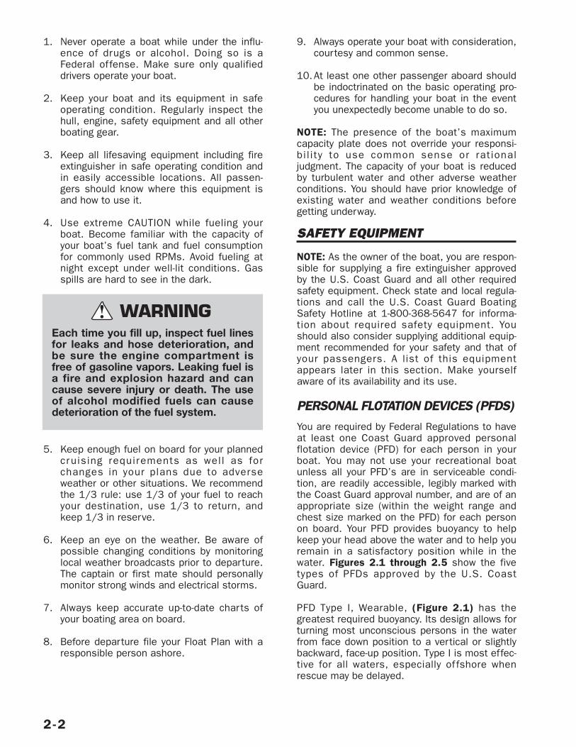
PERSONAL FLOTATION DEVICES (PFDS)You are required by Federal Regulations to haveat least one Coast Guard approved personalflotation device (PFD) for each person in yourboat. You may not use your recreational boatunless all your PFD’s are in serviceable condi-tion, are readily accessible, legibly marked withthe Coast Guard approval number, and are of anappropriate size (within the weight range andchest size marked on the PFD) for each personon board. Your PFD provides buoyancy to helpkeep your head above the water and to help youremain in a satisfactory position while in thewater. Figures 2.1 through 2.5 show the fivetypes of PFDs approved by the U.S. CoastGuard.
PFD Type I, Wearable, (Figure 2.1) has thegreatest required buoyancy. Its design allows forturning most unconscious persons in the waterfrom face down position to a vertical or slightlybackward, face-up position. Type I is most effec-tive for all waters, especially of fshore whenrescue may be delayed.
2-2
Each time you fill up, inspect fuel linesfor leaks and hose deterioration, andbe sure the engine compartment isfree of gasoline vapors. Leaking fuel isa fire and explosion hazard and cancause severe injury or death. The useof alcohol modified fuels can causedeterioration of the fuel system.
WARNING!
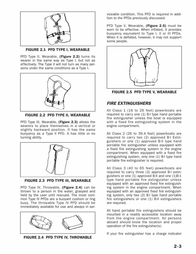
PFD Type II, Wearable, (Figure 2.2) turns itswearer in the same way as Type I, but not aseffectively. The Type II will not turn as many per-sons under the same conditions as a Type I.
PFD Type III, Wearable, (Figure 2.3) allows thewearers to place themselves in a ver tical orslightly backward position. It has the samebuoyancy as a Type II PFD. It has little or noturning ability.
PFD Type IV, Throwable, (Figure 2.4) can bethrown to a person in the water, grasped andheld by the user until rescued. The most com-mon Type IV PFDs are a buoyant cushion or ringbuoy. The throwable Type IV PFD should beimmediately available for use and always in ser-
viceable condition. This PFD is required in addi-tion to the PFDs previously discussed.
PFD Type V, Wearable, (Figure 2.5) must beworn to be effective. When inflated, it providesbuoyancy equivalent to Type I, II or III PFDs.When it is deflated, however, it may not supportsome people.
FIRE EXTINGUISHERSAll Class 1 (16 to 26 feet) powerboats arerequired to carry one (1) B-I type hand portablefire extinguisher unless the boat is equippedwith a fixed fire extinguishing system in theengine compartment.
All Class 2 (26 to 39.4 feet) powerboats arerequired to carr y two (2) approved B-I Extin-guishers or one (1) approved B-II type handportable fire extinguisher unless equipped witha fixed fire extinguishing system in the enginecompartment. When equipped with a fixed fireextinguishing system, only one (1) B-I type handportable fire extinguisher is required.
All Class 3 (40 to 65 feet) powerboats arerequired to carry three (3) approved B-I extin-guishers or one (1) approved B-II and one (1)B-1type hand por table fire extinguisher unlessequipped with an approved fixed fire extinguish-ing system in the engine compartment. Whenequipped with an approved fixed fire extinguish-ing system, only two (2) B-I type hand portablefire extinguishers or one (1) B-II extinguishersare required.
All hand portable fire extinguishers should bemounted in a readily accessible location awayfrom the engine compar tment. All personsaboard should know the location and properoperation of the fire extinguisher(s).
If your fire extinguisher has a charge indicator
2-3
FIGURE 2.1 PFD TYPE I, WEARABLE
FIGURE 2.2 PFD TYPE II, WEARABLE
FIGURE 2.3 PFD TYPE III, WEARABLE
FIGURE 2.4 PFD TYPE IV, THROWABLE
FIGURE 2.5 PFD TYPE V, WEARABLE
gauge, cold or hot weather may have an effecton the gauge reading. Consult the instructionmanual supplied with the fire extinguisher to
determine the accuracy of the gauge.
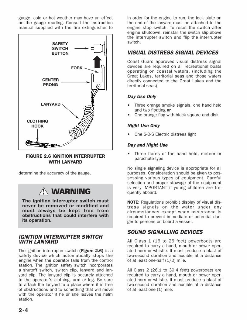
IGNITION INTERRUPTER SWITCHWITH LANYARDThe ignition interrupter switch (Figure 2.6) is asafety device which automatically stops theengine when the operator falls from the controlstation. The ignition safety switch incorporatesa shutoff switch, switch clip, lanyard and lan-yard clip. The lanyard clip is securely attachedto the operator’s clothing, arm or leg. Be sureto attach the lanyard to a place where it is freeof obstructions and to something that will movewith the operator if he or she leaves the helmstation.
In order for the engine to run, the lock plate onthe end of the lanyard must be attached to theengine stop switch. To reset the switch afterengine shutdown, reinstall the switch slip abovethe interrupter switch and flip the interrupterswitch.
VISUAL DISTRESS SIGNAL DEVICESCoast Guard approved visual distress signaldevices are required on all recreational boatsoperating on coastal waters, (including theGreat Lakes, territorial seas and those watersdirectly connected to the Great Lakes and theterritorial seas)
Day Use Only
• Three orange smoke signals, one hand heldand two floating or
• One orange flag with black square and disk
Night Use Only
• One S-O-S Electric distress light
Day and Night Use
• Three flares of the hand held, meteor orparachute type
No single signaling device is appropriate for allpurposes. Consideration should be given to pos-sessing various types of equipment. Carefulselection and proper stowage of the equipmentis very IMPORTANT if young children are fre-quently aboard.
NOTE: Regulations prohibit display of visual dis-tress signals on the water under anycircumstances except when assistance isrequired to prevent immediate or potential dan-ger to persons on board a vessel.
SOUND SIGNALLING DEVICESAll Class 1 (16 to 26 feet) powerboats arerequired to carry a hand, mouth or power oper-ated horn or whistle. It must produce a blast oftwo-second duration and audible at a distanceof at least one-half (1/2) mile.
All Class 2 (26.1 to 39.4 feet) powerboats arerequired to carry a hand, mouth or power oper-ated horn or whistle. It must produce a blast oftwo-second duration and audible at a distanceof at least one (1) mile.
2-4
FIGURE 2.6 IGNITION INTERRUPTER WITH LANYARD
The ignition interrupter switch mustnever be removed or modified andmust always be kept free fromobstructions that could interfere withits operation.
WARNING!
SAFETYSWITCHBUTTON
FORK
CENTERPRONG
LANYARD
CLOTHINGHOOK
ADDITIONAL RECOMMENDEDEQUIPMENTThe following list (not an exhaustive list) indi-cates some additional recommended equipmentwhich should be considered for safe, enjoyableboating.
Tools
• Spark plug wrench• Hammer• Screwdrivers• Jackknife• Pliers• Electricians tape• Adjustable wrench• Lubricating oil• Prop wrench• Duct tape
Spare Parts
• Extra Bulbs• Spare Propeller• Extra fuses• Extra drain plug• Spark plugs • Spare wire• Extra prop nut/washer
Basic Gear
• Flashlight• Spare batteries• Tow line• Oar or paddle• Mooring lines• Compass• Dock fenders• Distress signals• First aid kit• Boat hook• Foul weather gear• VHF Radio• EPIRB• Suntan lotion• Extra warm clothing• Charts• Second Anchor & line• Ring life buoy with length of line attached • Dewatering device (pump or bailer)• Emergency supply of drinking water and food
SAFE BOATING COURSES
Your local U.S. Coast Guard Auxiliary and theU.S. Power Squadrons of fer comprehensivesafe boating classes several times a year. Youmay contact the Boat/U.S. Foundation at 1-800-336-BOAT (2628) or, in Virginia, 1-800-245-BOAT (2628) for a course schedulein your area. Also contact your local U.S. CoastGuard Auxiliary or Power Squadron Flotilla forthe time and place of their next scheduledclass.
DRUGS AND ALCOHOL
The operator is responsible for the safety of allpassengers. Refrain from the use of drugsand/or alcohol while operating your boat. Opera-tion of motorized vessels while under theinfluence is a Federal offense carrying a signifi-cant penalty. The use of drugs and/or alcoholwill decrease reaction time, impede judgment,impair vision and inhibit your ability to safelyoperate a boat.
SAFE OPERATION
Avoid product misuse including but not limitedto the following actions:
• Riding seat back, gunwale, engine cover,bow or in other unsafe positions.
• Failure to use handholds or and other safetyhardware.
• Overloading or improper handling.
• Excessive speeds for operating conditions orspeeds exceeding the local limit. Allowenough distance to stop in an emergency.Observe “No Wake” warnings. The wake fromyour boat can jeopardize the safety of others.
2-5
Alcohol consumption and boating donot mix. Operating any boat whileintoxicated or under the influence ofdrugs is both dangerous and illegal.Impaired vision or judgment on thewater can quickly lead to disaster.Driving any boat, requires sober, atten-tive care. Federal laws prohibitoperating a boat under the influence ofalcohol or drugs. These laws are vigor-ously enforced.
WARNING!
• Use in weather or sea conditions beyond theskill or experience of the operator or thecomfortable capability of the boat or pas-sengers.
• Continued operation with operator’s visibilityblocked or impaired.
• Operating under the influence of drugs oralcohol.
POWER CAPACITYDo not exceed the maximum engine power rat-ing stated on the certification plate attached toyour boat.
PASSENGER SAFETYBe sure at least one of your passengers isfamiliar with the operation and safety aspects ofthe boat in case of an emergency. Show all pas-sengers the location of emergency equipmentand explain how to use it. Don’t allow passen-gers to drag their feet or hands in the water orsit on the bow, deck, or gunwale while the boatis moving.
OPERATION BY MINORSMinors should always be supervised by an adultwhenever operating a boat. Many states havelaws regarding the minimum age and licensingrequirements of minors. Be sure to contact thestate boating authorities for information.
2-6
2-7
CARBON MONOXIDE
Burning any material containing carbon produces carbon monoxide. A common source is the exhaustfumes from your boat’s engines and generator. Other sources include fumes from open flame devicessuch as cooking ranges and charcoal grills.
Even with the best boat design and construction, CO may still accumulate in accommodation spaces under cer-tain conditions. Continually observe passengers for symptoms of CO poisoning.
In high concentrations, CO can be fatal within minutes. In lower concentrations, its effects are cumula-tive and can be just as lethal over time. Watch for these are common symptoms of CO poisoning:
• Headaches • Drowsiness • Nausea• Dizziness • Fatigue • Vomiting • Itchy, watering eyes • Flushed appearance • Throbbing temples• Incoherence • Ringing in the ears • Difficulty breathing• Convulsions • Physical collapse
If you observe any of the above symptoms, begin treatment immediately.
• Evacuate the area• Move the victim to fresh air. Administer oxygen if available. Get medical help.• Open all windows and hatches to ventilate the area.• Investigate the source of CO and take immediate corrective action.
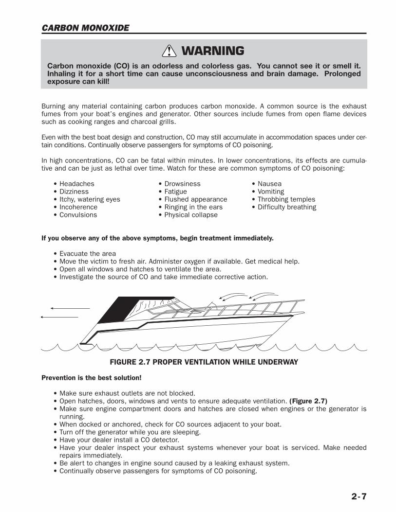
FIGURE 2.7 PROPER VENTILATION WHILE UNDERWAY
Prevention is the best solution!
• Make sure exhaust outlets are not blocked.• Open hatches, doors, windows and vents to ensure adequate ventilation. (Figure 2.7)• Make sure engine compartment doors and hatches are closed when engines or the generator is
running.• When docked or anchored, check for CO sources adjacent to your boat.• Turn off the generator while you are sleeping.• Have your dealer install a CO detector.• Have your dealer inspect your exhaust systems whenever your boat is serviced. Make needed
repairs immediately.• Be alert to changes in engine sound caused by a leaking exhaust system.• Continually observe passengers for symptoms of CO poisoning.
Carbon monoxide (CO) is an odorless and colorless gas. You cannot see it or smell it.Inhaling it for a short time can cause unconsciousness and brain damage. Prolongedexposure can kill!
WARNING!
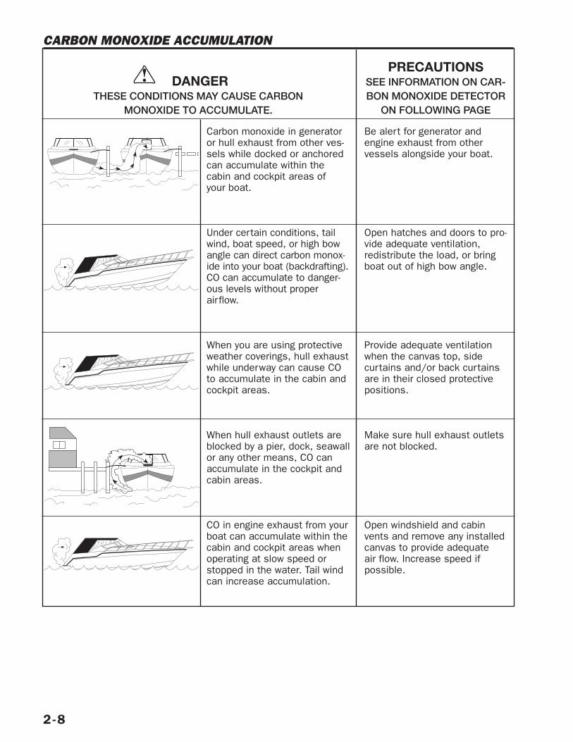
Carbon monoxide in generatoror hull exhaust from other ves-sels while docked or anchoredcan accumulate within thecabin and cockpit areas of your boat.
Under certain conditions, tailwind, boat speed, or high bowangle can direct carbon monox-ide into your boat (backdrafting).CO can accumulate to danger-ous levels without properairflow.
When you are using protectiveweather coverings, hull exhaustwhile underway can cause COto accumulate in the cabin andcockpit areas.
When hull exhaust outlets areblocked by a pier, dock, seawallor any other means, CO canaccumulate in the cockpit andcabin areas.
CO in engine exhaust from yourboat can accumulate within thecabin and cockpit areas whenoperating at slow speed orstopped in the water. Tail windcan increase accumulation.
Be alert for generator andengine exhaust from other vessels alongside your boat.
Open hatches and doors to pro-vide adequate ventilation,redistribute the load, or bringboat out of high bow angle.
Provide adequate ventilationwhen the canvas top, side curtains and/or back curtainsare in their closed protectivepositions.
Make sure hull exhaust outletsare not blocked.
Open windshield and cabinvents and remove any installedcanvas to provide adequate air flow. Increase speed if possible.
DANGERTHESE CONDITIONS MAY CAUSE CARBON
MONOXIDE TO ACCUMULATE.
PRECAUTIONSSEE INFORMATION ON CAR-BON MONOXIDE DETECTOR
ON FOLLOWING PAGE
2-8
CARBON MONOXIDE ACCUMULATION
!
CARBON MONOXIDE (CO) DETECTORWe strongly recommend you have marine gradeCO detectors installed in boats with canvasenclosures and in any boats with enclosed sleep-ing areas. Monitors are available from yourdealer. Monitors should be professionallyinstalled, calibrated, and tested.
NOTE: A CO detector is not a gas fuel vapordetector. Gas fuel vapor detectors do not moni-tor the buildup of carbon monoxide in anenclosed area.
WATER SPORTS
Water skiing, kneeboarding or riding a towed,inflatable apparatus are some of the more pop-ular water sports. Taking part in any water sportrequires increased safety awareness by the par-ticipant and the boat operator. If you have neverpulled someone behind your boat before, it is agood idea to spend some hours as an observer,working with and learning from an experienceddriver. It is also important to be aware of theskill and experience of the person being pulled.
Everyone participating in a water sport shouldobserve these guidelines:
1. Allow only capable swimmers to take part inany water sport.
2. Always wear a personal flotation device (PFD)approved by the U.S. Coast Guard. Wearinga properly designed PFD will help a stunnedor unconscious person stay afloat.
3. Always participate in water sports in safeareas. Stay away from other boats,beaches, swimmers and heavily traveledwaterways.
4. Be considerate to others you share thewater with.
6. Give immediate attention to a person who hasfallen. He or she is vulnerable in the wateralone and may not be seen by other boaters.
7. Approach a person in the water from the leeside (opposite the direction of the wind). Stopthe motor before coming close to the person.
8. Turn off engine and anchor your boat beforeswimming.
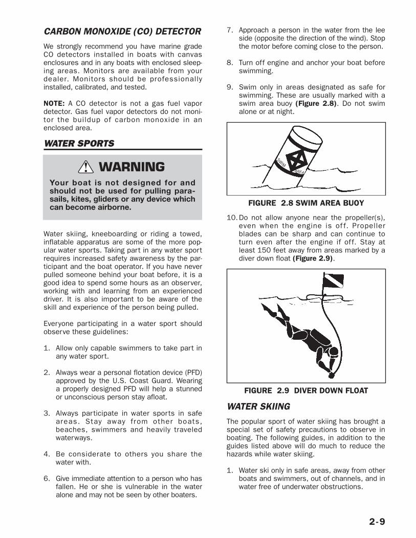
9. Swim only in areas designated as safe forswimming. These are usually marked with aswim area buoy (Figure 2.8). Do not swimalone or at night.
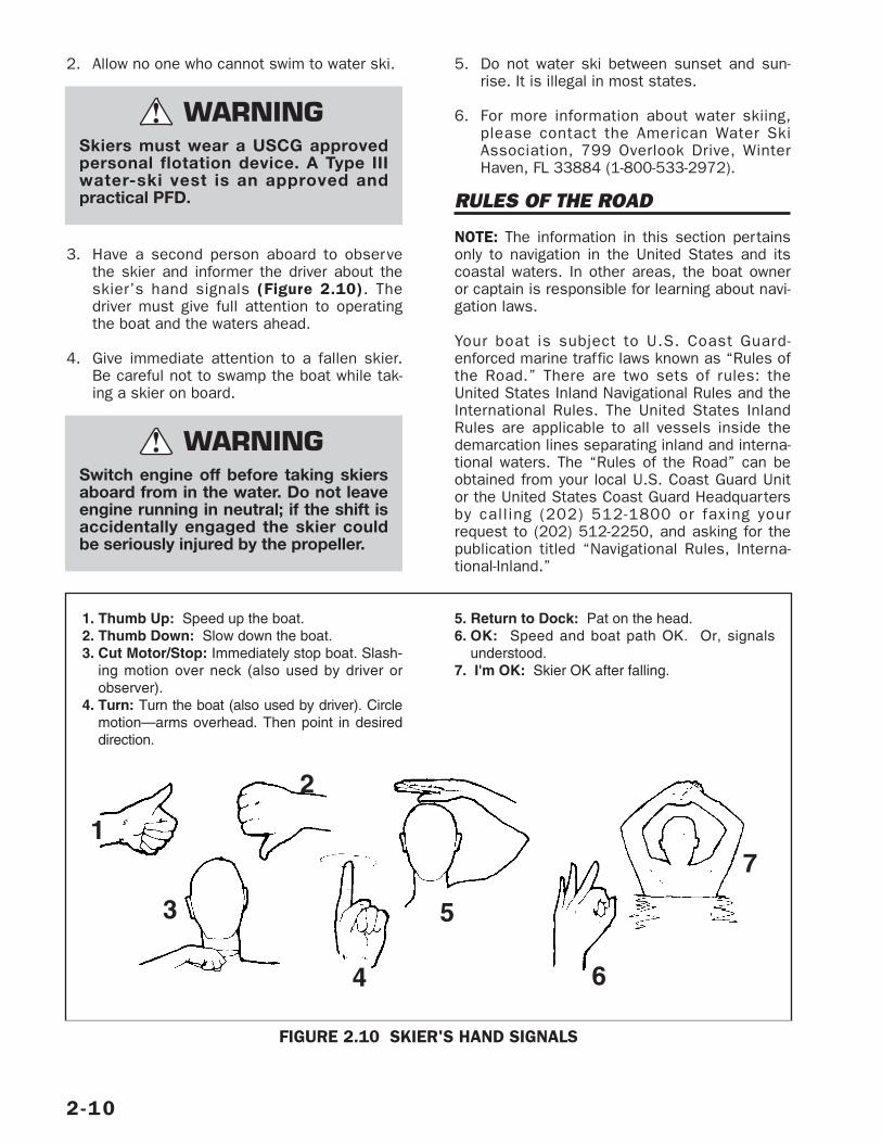
10.Do not allow anyone near the propeller(s),even when the engine is of f. Propellerblades can be sharp and can continue toturn even after the engine if of f. Stay atleast 150 feet away from areas marked by adiver down float (Figure 2.9).
WATER SKIINGThe popular sport of water skiing has brought aspecial set of safety precautions to observe inboating. The following guides, in addition to theguides listed above will do much to reduce thehazards while water skiing.
1. Water ski only in safe areas, away from otherboats and swimmers, out of channels, and inwater free of underwater obstructions.
2-9
SMI
W
AREA
FIGURE 2.8 SWIM AREA BUOY
FIGURE 2.9 DIVER DOWN FLOAT
Your boat is not designed for andshould not be used for pulling para-sails, kites, gliders or any device whichcan become airborne.
WARNING!
2. Allow no one who cannot swim to water ski.
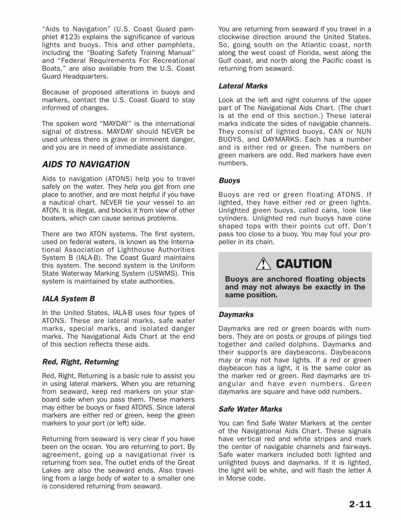
3. Have a second person aboard to observethe skier and informer the driver about theskier’s hand signals (Figure 2.10). Thedriver must give full attention to operatingthe boat and the waters ahead.
4. Give immediate attention to a fallen skier.Be careful not to swamp the boat while tak-ing a skier on board.
5. Do not water ski between sunset and sun-rise. It is illegal in most states.
6. For more information about water skiing,please contact the American Water SkiAssociation, 799 Overlook Drive, WinterHaven, FL 33884 (1-800-533-2972).
RULES OF THE ROAD
NOTE: The information in this section pertainsonly to navigation in the United States and itscoastal waters. In other areas, the boat owneror captain is responsible for learning about navi-gation laws.
Your boat is subject to U.S. Coast Guard-enforced marine traffic laws known as “Rules ofthe Road.” There are two sets of rules: theUnited States Inland Navigational Rules and theInternational Rules. The United States InlandRules are applicable to all vessels inside thedemarcation lines separating inland and interna-tional waters. The “Rules of the Road” can beobtained from your local U.S. Coast Guard Unitor the United States Coast Guard Headquartersby call ing (202) 512-1800 or faxing yourrequest to (202) 512-2250, and asking for thepublication titled “Navigational Rules, Interna-tional-Inland.”
2-10
1. Thumb Up: Speed up the boat.2. Thumb Down: Slow down the boat.3. Cut Motor/Stop: Immediately stop boat. Slash-
ing motion over neck (also used by driver orobserver).
4. Turn: Turn the boat (also used by driver). Circlemotion—arms overhead. Then point in desireddirection.
5. Return to Dock: Pat on the head.6. OK: Speed and boat path OK. Or, signals
understood.7. I'm OK: Skier OK after falling.
Skiers must wear a USCG approvedpersonal flotation device. A Type IIIwater-ski vest is an approved andpractical PFD.
WARNING!
1
2
3
4
5
6
7
Switch engine off before taking skiersaboard from in the water. Do not leaveengine running in neutral; if the shift isaccidentally engaged the skier couldbe seriously injured by the propeller.
WARNING!
FIGURE 2.10 SKIER'S HAND SIGNALS
“Aids to Navigation” (U.S. Coast Guard pam-phlet #123) explains the significance of variouslights and buoys. This and other pamphlets,including the “Boating Safety Training Manual”and “Federal Requirements For RecreationalBoats,” are also available from the U.S. CoastGuard Headquarters.
Because of proposed alterations in buoys andmarkers, contact the U.S. Coast Guard to stayinformed of changes.
The spoken word “MAYDAY” is the internationalsignal of distress. MAYDAY should NEVER beused unless there is grave or imminent danger,and you are in need of immediate assistance.
AIDS TO NAVIGATIONAids to navigation (ATONS) help you to travelsafely on the water. They help you get from oneplace to another, and are most helpful if you havea nautical chart. NEVER tie your vessel to anATON. It is illegal, and blocks it from view of otherboaters, which can cause serious problems.
There are two ATON systems. The first system,used on federal waters, is known as the Interna-tional Association of Lighthouse AuthoritiesSystem B (IALA-B). The Coast Guard maintainsthis system. The second system is the UniformState Waterway Marking System (USWMS). Thissystem is maintained by state authorities.
IALA System B
In the United States, IALA-B uses four types ofATONS. These are lateral marks, safe watermarks, special marks, and isolated dangermarks. The Navigational Aids Chart at the endof this section reflects these aids.
Red, Right, Returning
Red, Right, Returning is a basic rule to assist youin using lateral markers. When you are returningfrom seaward, keep red markers on your star-board side when you pass them. These markersmay either be buoys or fixed ATONS. Since lateralmarkers are either red or green, keep the greenmarkers to your port (or left) side.
Returning from seaward is very clear if you havebeen on the ocean. You are returning to port. Byagreement, going up a navigational river isreturning from sea. The outlet ends of the GreatLakes are also the seaward ends. Also travel-ling from a large body of water to a smaller oneis considered returning from seaward.
You are returning from seaward if you travel in aclockwise direction around the United States.So, going south on the Atlantic coast, nor thalong the west coast of Florida, west along theGulf coast, and north along the Pacific coast isreturning from seaward.
Lateral Marks
Look at the left and right columns of the upperpart of The Navigational Aids Chart. (The chartis at the end of this section.) These lateralmarks indicate the sides of navigable channels.They consist of lighted buoys, CAN or NUNBUOYS, and DAYMARKS. Each has a numberand is either red or green. The numbers ongreen markers are odd. Red markers have evennumbers.
Buoys
Buoys are red or green floating ATONS. Iflighted, they have either red or green lights.Unlighted green buoys, called cans, look likecylinders. Unlighted red nun buoys have coneshaped tops with their points cut of f. Don’tpass too close to a buoy. You may foul your pro-peller in its chain.
Daymarks
Daymarks are red or green boards with num-bers. They are on posts or groups of pilings tiedtogether and called dolphins. Daymarks andtheir suppor ts are daybeacons. Daybeaconsmay or may not have lights. If a red or greendaybeacon has a light, it is the same color asthe marker red or green. Red daymarks are tri-angular and have even numbers. Greendaymarks are square and have odd numbers.
Safe Water Marks
You can find Safe Water Markers at the centerof the Navigational Aids Chart. These signalshave vertical red and white stripes and markthe center of navigable channels and fairways.Safe water markers included both lighted andunlighted buoys and daymarks. If it is lighted,the light will be white, and will flash the letter Ain Morse code.
2-11
Buoys are anchored floating objectsand may not always be exactly in thesame position.
CAUTION!
Preferred Channel Markers
Preferred Channel Markers have horizontal redand green bands. If lighted, the color of the lightis the same as the top of the band. They showthe preferred channel for you to use at a junc-tion point. Be sure to notice the color of the topband, and treat it as any other marker youwould of that color. If the band is red and youare returning from seaward, keep the marker toyour right.
Lights on Markers
Most lights on markers flash on and off. Otherssuch as lights on aids with no lateral signifi-cance are fixed. They stay on all night. ATONlights flash in regular patterns. For example,they may flash ever y three seconds, or ingroups such as two flashes and a pause. Thereare a number of flashing patterns, which helpyou identify the light at night. To identify a light,note its color and pattern or timing of flashes,and compare it to your chart to find its location.
THE UNIFORM STATE WATERWAYMARKING SYSTEMThere are four kinds of markers in the systemRegulatory, Informational, Cardinal and Lateral.
USWMS Regulatory Markers
The markers in this system are either signs orbuoys. Signs are square with orange borders.Regulator y buoys are white and shaped likecylinders. They have horizontal orange bandsnear their tops and just above the surface ofthe water.
An orange circle on a marker means a con-trolled area. A message such as No Wake, IdleSpeed, No Skiing, or 5 MPH may appear on themarker.
An orange diamond means danger. If the dia-mond has an orange cross inside it, don’t enterthe area. The reason you should stay out, suchas “Swim Area” may be printed in black on themarker.
USWMS Informational Markers
USWMS informational markers are white signswith orange borders. They give information suchas direction, distance, and location.
USWMS Lateral Markers
Lateral buoys in the USWMS system are eitherred or black. They have numbers, and blackbuoys may have green reflectors or lights. Theyare the equivalent of green buoys in the IALA-Bsystem. Red buoys may have red reflectors orlights, as well. Red and black buoys are usuallyfound in pairs pass between them.
A Special Sign
In Florida, you may see a special sign: “Caution,Manatee Area”. When you see this sign, slowdown to idle speed. Manatees, an endangeredspecies, are passive, large, slow-moving mam-mals. Many manatees are seriously injured orkilled each year by boat propellers.
GENERAL RULES OF SEAMANSHIP
1. Cross waves at right angles.
2. When caught in heavy water or squalls,head either directly into the waves or at aslight angle. Reduce speed, but maintainenough power to maneuver your boat safely.
3. Keep your speed under control. Respect therights of boaters engaged in fishing, swim-ming, water skiing or diving. Give them“wide berth”.
4. When meeting a boat head on, keep to theright whenever possible.
5. When two boats cross, the boat to the rightor starboard has the right of way.
6. When overtaking or passing, the boat beingpassed has the right of way. The boat beingpassed is required to maintain the samecourse and speed.
RIGHT-OF-WAYIn general, boats with less maneuverability haveright-of-way over more agile craft. In your powerboat, you must stay out of the way of the follow-ing vessels:
• A vessel not under command or aground.Due to their circumstances, these vesselshave no maneuverability.
• A vessel restricted in its maneuverability.These vessels are per forming work whichlimits their maneuverability such as: sur-veying, dredging, laying pipe or cable, or
2-12
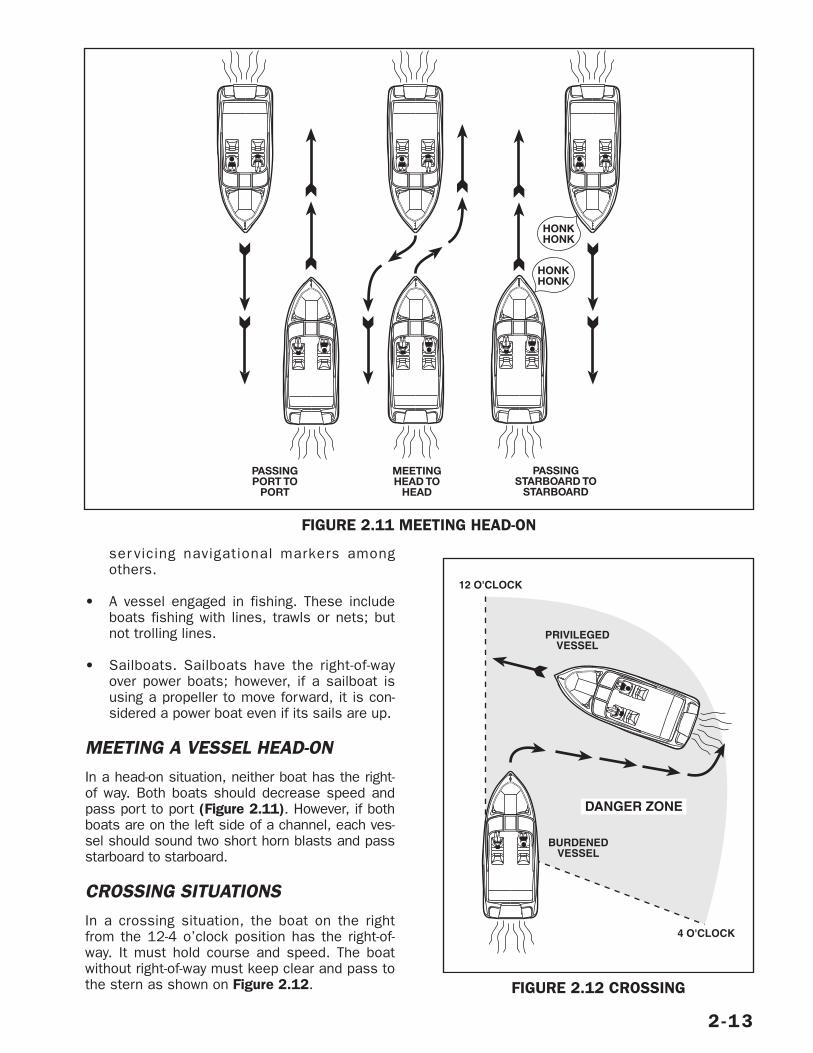
ser vicing navigational markers amongothers.
• A vessel engaged in fishing. These includeboats fishing with lines, trawls or nets; butnot trolling lines.
• Sailboats. Sailboats have the right-of-wayover power boats; however, if a sailboat isusing a propeller to move forward, it is con-sidered a power boat even if its sails are up.
MEETING A VESSEL HEAD-ONIn a head-on situation, neither boat has the right-of way. Both boats should decrease speed andpass port to port (Figure 2.11). However, if bothboats are on the left side of a channel, each ves-sel should sound two short horn blasts and passstarboard to starboard.
CROSSING SITUATIONSIn a crossing situation, the boat on the rightfrom the 12-4 o’clock position has the right-of-way. It must hold course and speed. The boatwithout right-of-way must keep clear and pass tothe stern as shown on Figure 2.12.
2-13
PASSINGPORT TO
PORT
PASSINGSTARBOARD TO
STARBOARD
MEETINGHEAD TO
HEAD
HONKHONK
HONKHONK
FIGURE 2.11 MEETING HEAD-ON
PRIVILEGEDVESSEL
BURDENEDVESSEL
12 O'CLOCK
4 O'CLOCK
DANGER ZONE
FIGURE 2.12 CROSSING
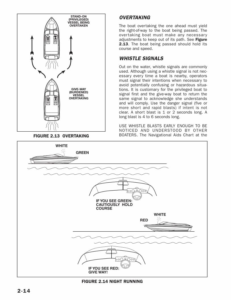
OVERTAKINGThe boat overtaking the one ahead must yieldthe right-of-way to the boat being passed. Theover taking boat must make any necessar yadjustments to keep out of its path. See Figure2.13. The boat being passed should hold itscourse and speed.
WHISTLE SIGNALSOut on the water, whistle signals are commonlyused. Although using a whistle signal is not nec-essary every time a boat is nearby, operatorsmust signal their intentions when necessary toavoid potentially confusing or hazardous situa-tions. It is customary for the privileged boat tosignal first and the give-way boat to return thesame signal to acknowledge she understandsand will comply. Use the danger signal (five ormore shor t and rapid blasts) if intent is notclear. A short blast is 1 or 2 seconds long. Along blast is 4 to 6 seconds long.
USE WHISTLE BLASTS EARLY ENOUGH TO BENOTICED AND UNDERSTOOD BY OTHERBOATERS. The Navigational Aids Chart at the
2-14
GIVE-WAY(BURDENED)
VESSELOVERTAKING
STAND-ON(PRIVILEGED)
VESSEL BEINGOVERTAKEN
FIGURE 2.13 OVERTAKING
WHITE
GREEN
WHITE
RED
IF YOU SEE GREEN:CAUTIOUSLY HOLDCOURSE
IF YOU SEE RED:GIVE WAY!
FIGURE 2.14 NIGHT RUNNING
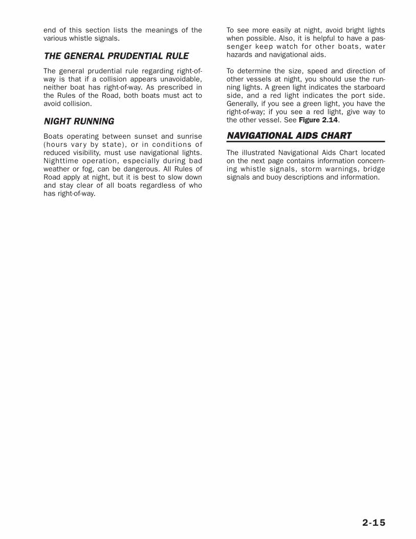
2-15
end of this section lists the meanings of thevarious whistle signals.
THE GENERAL PRUDENTIAL RULEThe general prudential rule regarding right-of-way is that if a collision appears unavoidable,neither boat has right-of-way. As prescribed inthe Rules of the Road, both boats must act toavoid collision.
NIGHT RUNNINGBoats operating between sunset and sunrise(hours var y by state), or in conditions ofreduced visibility, must use navigational lights.Nighttime operation, especially during badweather or fog, can be dangerous. All Rules ofRoad apply at night, but it is best to slow downand stay clear of all boats regardless of whohas right-of-way.
To see more easily at night, avoid bright lightswhen possible. Also, it is helpful to have a pas-senger keep watch for other boats, waterhazards and navigational aids.
To determine the size, speed and direction ofother vessels at night, you should use the run-ning lights. A green light indicates the starboardside, and a red light indicates the port side.Generally, if you see a green light, you have theright-of-way; if you see a red light, give way tothe other vessel. See Figure 2.14.
NAVIGATIONAL AIDS CHART
The illustrated Navigational Aids Chart locatedon the next page contains information concern-ing whistle signals, storm warnings, bridgesignals and buoy descriptions and information.
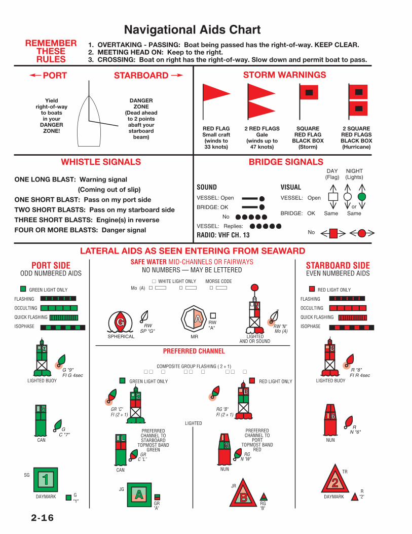
2-16
JR
RG"B"
PREFERREDCHANNEL TO
PORTTOPMOST BAND
REDRG
N "W"
NUN
1. OVERTAKING - PASSING: Boat being passed has the right-of-way. KEEP CLEAR.2. MEETING HEAD ON: Keep to the right.3. CROSSING: Boat on right has the right-of-way. Slow down and permit boat to pass.
STORM WARNINGS
RED FLAG 2 RED FLAGS SQUARE 2 SQUARESmall craft Gale RED FLAG RED FLAGS(winds to (winds up to BLACK BOX BLACK BOX33 knots) 47 knots) (Storm) (Hurricane)
WHISTLE SIGNALS
ONE LONG BLAST: Warning signal
(Coming out of slip)
ONE SHORT BLAST: Pass on my port side
TWO SHORT BLASTS: Pass on my starboard side
THREE SHORT BLASTS: Engine(s) in reverse
FOUR OR MORE BLASTS: Danger signal
BRIDGE SIGNALS
DANGERZONE
(Dead aheadto 2 pointsabaft yourstarboard
beam)
Yieldright-of-way
to boatsin your
DANGERZONE!
SOUNDVESSEL: Open
BRIDGE: OK
No
VESSEL: Replies:
RADIO: VHF CH. 13
VISUALVESSEL: Open
orBRIDGE: OK Same Same
No
DAY NIGHT(Flag) (Lights)
LATERAL AIDS AS SEEN ENTERING FROM SEAWARD
G "9"FI G 4sec
LIGHTED BUOY
GC "7"
CAN
SG
DAYMARK G"1"
EVEN NUMBERED AIDS
RED LIGHT ONLY
FLASHING
OCCULTING
QUICK FLASHING
ISOPHASE
R "8"FI R 4sec
LIGHTED BUOY
RN "6"
NUN
TR
RDAYMARK "2"
SAFE WATER MID-CHANNELS OR FAIRWAYSNO NUMBERS — MAY BE LETTERED
RW "N"Mo (A)
LIGHTEDAND OR SOUND
PREFERRED CHANNEL
COMPOSITE GROUP FLASHING ( 2 + 1)■■ ■■ ■■ ■■ ■■ ■■ ■■ ■■ ■■
GREEN LIGHT ONLY
GR "C"FI (2 + 1)
RED LIGHT ONLY
RG "B"FI (2 + 1)
LIGHTED
PREFERREDCHANNEL TOSTARBOARD
TOPMOST BANDGREEN
GRC "L"
CAN
JG
GR"A"
ODD NUMBERED AIDS
GREEN LIGHT ONLY
FLASHING
OCCULTING
QUICK FLASHING
ISOPHASE RWSP "G"
SPHERICAL
RW"A"
MR
■■ WHITE LIGHT ONLY MORSE CODEMo (A)
STARBOARDPORT
PORT SIDE STARBOARD SIDE
REMEMBERTHESERULES
Navigational Aids Chart
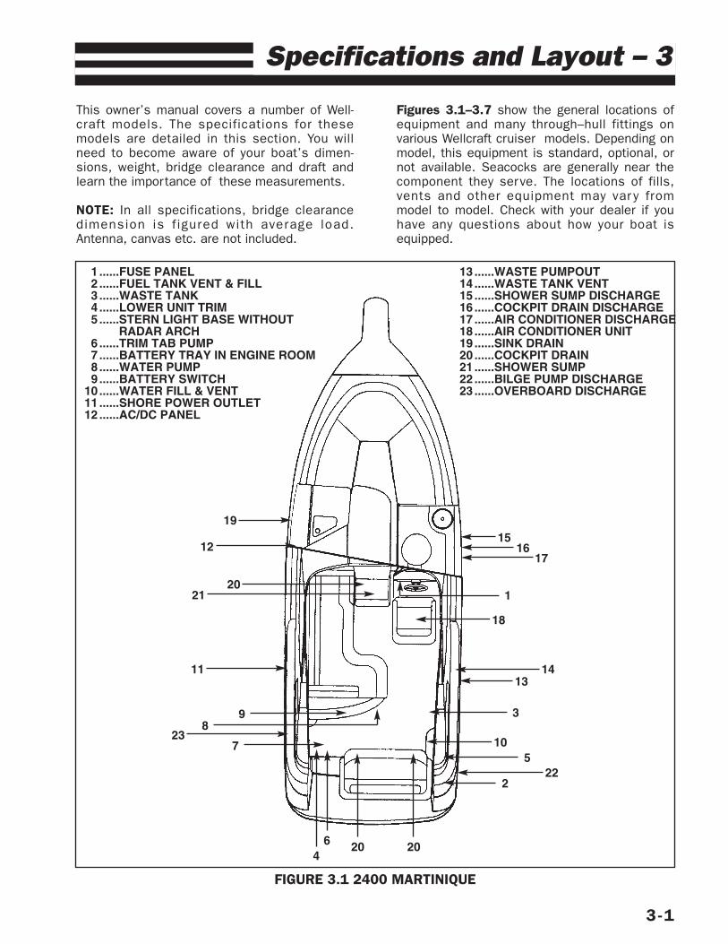
This owner’s manual covers a number of Well-craft models. The specifications for thesemodels are detailed in this section. You willneed to become aware of your boat’s dimen-sions, weight, bridge clearance and draft andlearn the importance of these measurements.
NOTE: In all specifications, bridge clearancedimension is f igured with average load.Antenna, canvas etc. are not included.
Figures 3.1–3.7 show the general locations ofequipment and many through–hull fittings onvarious Wellcraft cruiser models. Depending onmodel, this equipment is standard, optional, ornot available. Seacocks are generally near thecomponent they serve. The locations of fills,vents and other equipment may var y frommodel to model. Check with your dealer if youhave any questions about how your boat isequipped.
3-1
Specifications and Layout – 3
FIGURE 3.1 2400 MARTINIQUE
1
1314
18
1617
15
3
10
225
2
64
7
89
23
20 20
11
2021
12
19
1 ......FUSE PANEL2 ......FUEL TANK VENT & FILL3 ......WASTE TANK4......LOWER UNIT TRIM5 ......STERN LIGHT BASE WITHOUT
RADAR ARCH6......TRIM TAB PUMP7......BATTERY TRAY IN ENGINE ROOM8......WATER PUMP9......BATTERY SWITCH
10 ......WATER FILL & VENT11 ......SHORE POWER OUTLET12 ......AC/DC PANEL
13 ......WASTE PUMPOUT14 ......WASTE TANK VENT15 ......SHOWER SUMP DISCHARGE16 ......COCKPIT DRAIN DISCHARGE17 ......AIR CONDITIONER DISCHARGE18 ......AIR CONDITIONER UNIT19 ......SINK DRAIN20 ......COCKPIT DRAIN21 ......SHOWER SUMP22 ......BILGE PUMP DISCHARGE23 ......OVERBOARD DISCHARGE
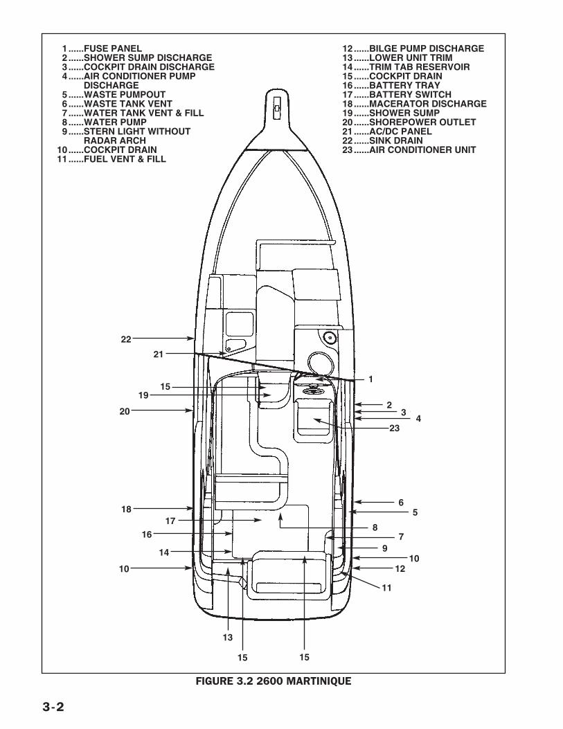
3-2
FIGURE 3.2 2600 MARTINIQUE
1 ......FUSE PANEL2 ......SHOWER SUMP DISCHARGE3......COCKPIT DRAIN DISCHARGE4......AIR CONDITIONER PUMP
DISCHARGE5......WASTE PUMPOUT6......WASTE TANK VENT7 ......WATER TANK VENT & FILL8 ......WATER PUMP9......STERN LIGHT WITHOUT
RADAR ARCH10 ......COCKPIT DRAIN11 ......FUEL VENT & FILL
1
23
423
6
1515
13
14
10
1617
18
1519
20
5
87
910
12
11
21
22
12 ......BILGE PUMP DISCHARGE13 ......LOWER UNIT TRIM14 ......TRIM TAB RESERVOIR15 ......COCKPIT DRAIN16 ......BATTERY TRAY17 ......BATTERY SWITCH18 ......MACERATOR DISCHARGE19 ......SHOWER SUMP20 ......SHOREPOWER OUTLET21 ......AC/DC PANEL22 ......SINK DRAIN23 ......AIR CONDITIONER UNIT
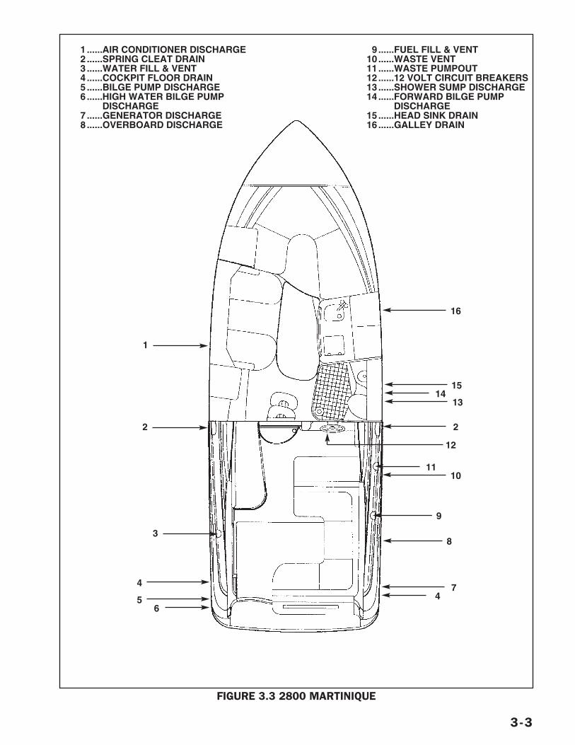
3-3
FIGURE 3.3 2800 MARTINIQUE
1 ......WATER TANK VENT2 ......AIR CONDITIONER DISCHARGE3......CIRCUIT BREAKERS ON HELM4......WATER FILL5 ......FUEL CROSS OVER VALVE6 ......BATTERIES (2)7 ......A/C SEACOCK & STRAINER8......GENSET9 ......FUEL TANK VENT
10 ......GENSET EXHAUST11 ......BILGE PUMP DISCHARGE12 ......ENGINE EXHAUST 13 ......FUEL FILL14 ......COCKPIT DRAINS15 ......CITY WATER INLET16 ......FUEL FILL
17 ......ENGINE EXHAUST 18 ......TRIM TAB RESERVOIR19 ......FUEL TANK VENT20 ......WASTE TANK VENT21 ......BILGE PUMP DISCHARGE22 ......SHOWER SUMP DISCHARGE23 ......SHORE POWER OUTLET24 ......TELEPHONE/TV OUTLET25 ......AC/DC PANEL 26 ......BATTERY SWITCHES27 ......FRESHWATER PUMP28 ......SHOWER SUMP29 ......WASTE PUMPOUT30 ......HEAD SINK DRAIN31 ......GALLEY SINK DRAIN
8
2
9
2
3
1
1 ......AIR CONDITIONER DISCHARGE2......SPRING CLEAT DRAIN3 ......WATER FILL & VENT4 ......COCKPIT FLOOR DRAIN5 ......BILGE PUMP DISCHARGE6......HIGH WATER BILGE PUMP
DISCHARGE7......GENERATOR DISCHARGE8......OVERBOARD DISCHARGE
9......FUEL FILL & VENT10 ......WASTE VENT11 ......WASTE PUMPOUT12 ......12 VOLT CIRCUIT BREAKERS13 ......SHOWER SUMP DISCHARGE14 ......FORWARD BILGE PUMP
DISCHARGE15 ......HEAD SINK DRAIN16 ......GALLEY DRAIN
4
56
74
1514
13
1110
16
12
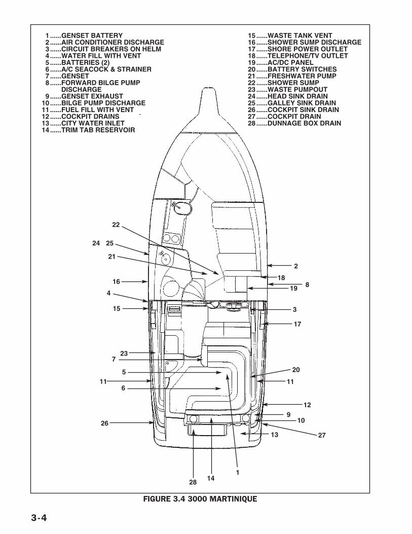
3-4
FIGURE 3.4 3000 MARTINIQUE
2
3
17
13
26
14
23
20
8
129
10
27
15
16
1 ......GENSET BATTERY2......AIR CONDITIONER DISCHARGE3......CIRCUIT BREAKERS ON HELM4......WATER FILL WITH VENT5 ......BATTERIES (2)6 ......A/C SEACOCK & STRAINER7......GENSET8 ......FORWARD BILGE PUMP
DISCHARGE9......GENSET EXHAUST
10 ......BILGE PUMP DISCHARGE11 ......FUEL FILL WITH VENT12 ......COCKPIT DRAINS13 ......CITY WATER INLET14 ......TRIM TAB RESERVOIR
15 ......WASTE TANK VENT16 ......SHOWER SUMP DISCHARGE17 ......SHORE POWER OUTLET18 ......TELEPHONE/TV OUTLET19 ......AC/DC PANEL 20 ......BATTERY SWITCHES21 ......FRESHWATER PUMP22 ......SHOWER SUMP23 ......WASTE PUMPOUT24 ......HEAD SINK DRAIN25 ......GALLEY SINK DRAIN26 ......COCKPIT SINK DRAIN27 ......COCKPIT DRAIN28 ......DUNNAGE BOX DRAIN
28
6
7
21
22
2524
115
4
11
19
18
1
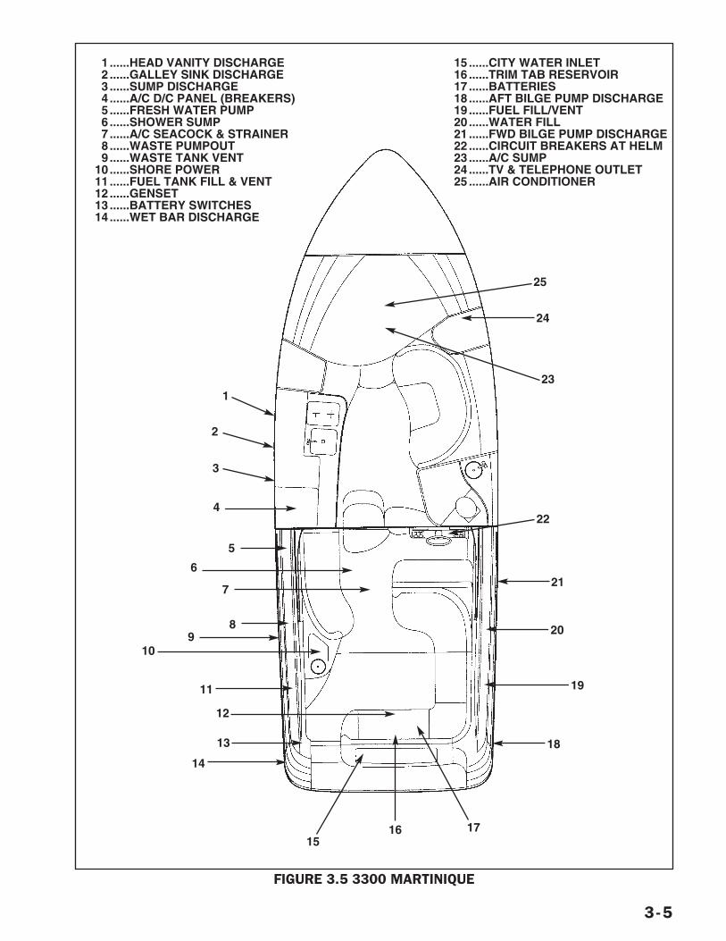
3-5
FIGURE 3.5 3300 MARTINIQUE
4
24
23
16
14
13
15
8
22
20
19
18
17
7
5
1 ......HEAD VANITY DISCHARGE2......GALLEY SINK DISCHARGE3......SUMP DISCHARGE4......A/C D/C PANEL (BREAKERS)5 ......FRESH WATER PUMP6......SHOWER SUMP7......A/C SEACOCK & STRAINER8......WASTE PUMPOUT9......WASTE TANK VENT
10 ......SHORE POWER11 ......FUEL TANK FILL & VENT12 ......GENSET13 ......BATTERY SWITCHES14 ......WET BAR DISCHARGE
15 ......CITY WATER INLET16 ......TRIM TAB RESERVOIR17 ......BATTERIES18 ......AFT BILGE PUMP DISCHARGE19 ......FUEL FILL/VENT20 ......WATER FILL21 ......FWD BILGE PUMP DISCHARGE22 ......CIRCUIT BREAKERS AT HELM23 ......A/C SUMP24 ......TV & TELEPHONE OUTLET25 ......AIR CONDITIONER
12
9
3
1
2
11
10
621
25
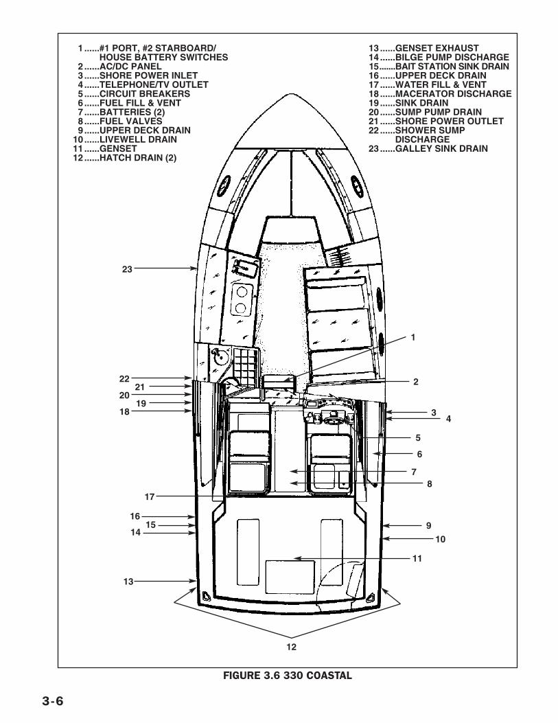
3-6
FIGURE 3.6 330 COASTAL
1 ......#1 PORT, #2 STARBOARD/HOUSE BATTERY SWITCHES
2......AC/DC PANEL3 ......SHORE POWER INLET4 ......TELEPHONE/TV OUTLET5 ......CIRCUIT BREAKERS6......FUEL FILL & VENT7 ......BATTERIES (2)8 ......FUEL VALVES9......UPPER DECK DRAIN
10 ......LIVEWELL DRAIN11 ......GENSET12 ......HATCH DRAIN (2)
13 ......GENSET EXHAUST14 ......BILGE PUMP DISCHARGE15.......BAIT STATION SINK DRAIN16 ......UPPER DECK DRAIN17 ......WATER FILL & VENT18 ......MACERATOR DISCHARGE19 ......SINK DRAIN20 ......SUMP PUMP DRAIN21 ......SHORE POWER OUTLET22 ......SHOWER SUMP
DISCHARGE23 ......GALLEY SINK DRAIN
1
2
34
5
6
17
2221
2019
18
78
9
10
11
12
13
23
1615
14
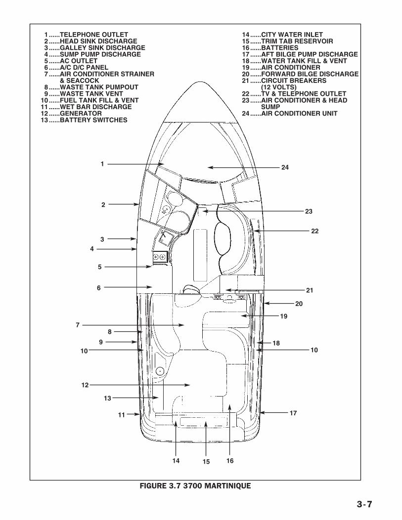
3-7
FIGURE 3.7 3700 MARTINIQUE
24
2
21
22
23
13
12
109
719
20
18
17
161514
34
1 ......TELEPHONE OUTLET2 ......HEAD SINK DISCHARGE3......GALLEY SINK DISCHARGE4......SUMP PUMP DISCHARGE5......AC OUTLET6 ......A/C D/C PANEL7 ......AIR CONDITIONER STRAINER
& SEACOCK8......WASTE TANK PUMPOUT9......WASTE TANK VENT
10 ......FUEL TANK FILL & VENT11 ......WET BAR DISCHARGE12 ......GENERATOR13 ......BATTERY SWITCHES
14 ......CITY WATER INLET15 ......TRIM TAB RESERVOIR16 ......BATTERIES17 ......AFT BILGE PUMP DISCHARGE18 ......WATER TANK FILL & VENT19 ......AIR CONDITIONER20 ......FORWARD BILGE DISCHARGE21 ......CIRCUIT BREAKERS
(12 VOLTS)22 ......TV & TELEPHONE OUTLET23 ......AIR CONDITIONER & HEAD
SUMP24 ......AIR CONDITIONER UNIT
11
8
6
5
1
10
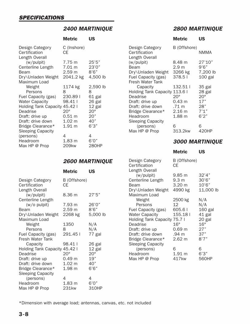
3-8
SPECIFICATIONS
2400 MARTINIQUE
Metric US
Design Category C (Inshore)Certification CELength Overall
(w/pulpit) 7.75 m 25’5”Centerline Length 7.01 m 23’0”Beam 2.59 m 8’6”Dry\Unladen Weight 2041.2 kg 4,500 lbMaximum Load
Weight 1174 kg 2,590 lbPersons 8 8
Fuel Capacity (gas) 230.89 l 61 galWater Capacity 98.41 l 26 galHolding Tank Capacity 45.42 l 12 galDeadrise 20° 20°Draft: drive up 0.51 m 20”Draft: drive down 1.02 m 40”Bridge Clearance* 1.91 m 6’3”Sleeping Capacity(persons) 4 4Headroom 1.83 m 6’0”Max HP @ Prop 209kw 280HP
2600 MARTINIQUE
Metric US
Design Category B (Offshore)Certification CELength Overall
(w/pulpit) 8.36 m 27’5”Centerline Length
(w/o pulpit) 7.93 m 26’0”Beam 2.59 m 8’6”Dry\Unladen Weight 2268 kg 5,000 lbMaximum Load
Weight 1350 N/APersons 8 N/A
Fuel Capacity (gas) 291.45 l 77 galFresh Water Tank
Capacity 98.41 l 26 galHolding Tank Capacity 45.42 l 12 galDeadrise 20° 20°Draft: drive up 0.49 m 19”Draft: drive down 1.02 m 40”Bridge Clearance* 1.98 m 6’6”Sleeping Capacity
(persons) 4 4Headroom 1.83 m 6’0”Max HP @ Prop 231kw 310HP
2800 MARTINIQUE
Metric US
Design Category B (Offshore)Certification NMMALength Overall(w/pulpit) 8.48 m 27’10”Beam 2.9 m 9’6”Dry\Unladen Weight 3266 kg 7,200 lbFuel Capacity (gas) 378.5 l 100 galFresh Water Tank
Capacity 132.51 l 35 galHolding Tank Capacity 113.6 l 28 galDeadrise 20° 20°Draft: drive up 0.43 m 17”Draft: drive down .71 m 28”Bridge Clearance* 2.16 m 7’1”Headroom 1.88 m 6’2”Sleeping Capacity
(persons) 6 6Max HP @ Prop 313.2kw 420HP
3000 MARTINIQUE
Metric US
Design Category B (Offshore)Certification CELength Overall
(w/pulpit) 9.85 m 32’4”Centerline Length 9.3 m 30’6”Beam 3.20 m 10’6”Dry\Unladen Weight 4990 kg 11,000 lbMaximum Load
Weight 2500 kg N/APersons 12 N/A
Fuel Capacity (gas) 605.6 l 160 galWater Capacity 155.18 l 41 galHolding Tank Capacity 75.7 l 20 galDeadrise 16° 16°Draft: drive up 0.69 m 27”Draft: drive down .94 m 37”Bridge Clearance* 2.62 m 8’7”Sleeping Capacity
(persons) 6 6Headroom 1.91 m 6’3”Max HP @ Prop 417kw 560HP
*Dimension with average load; antennas, canvas, etc. not included
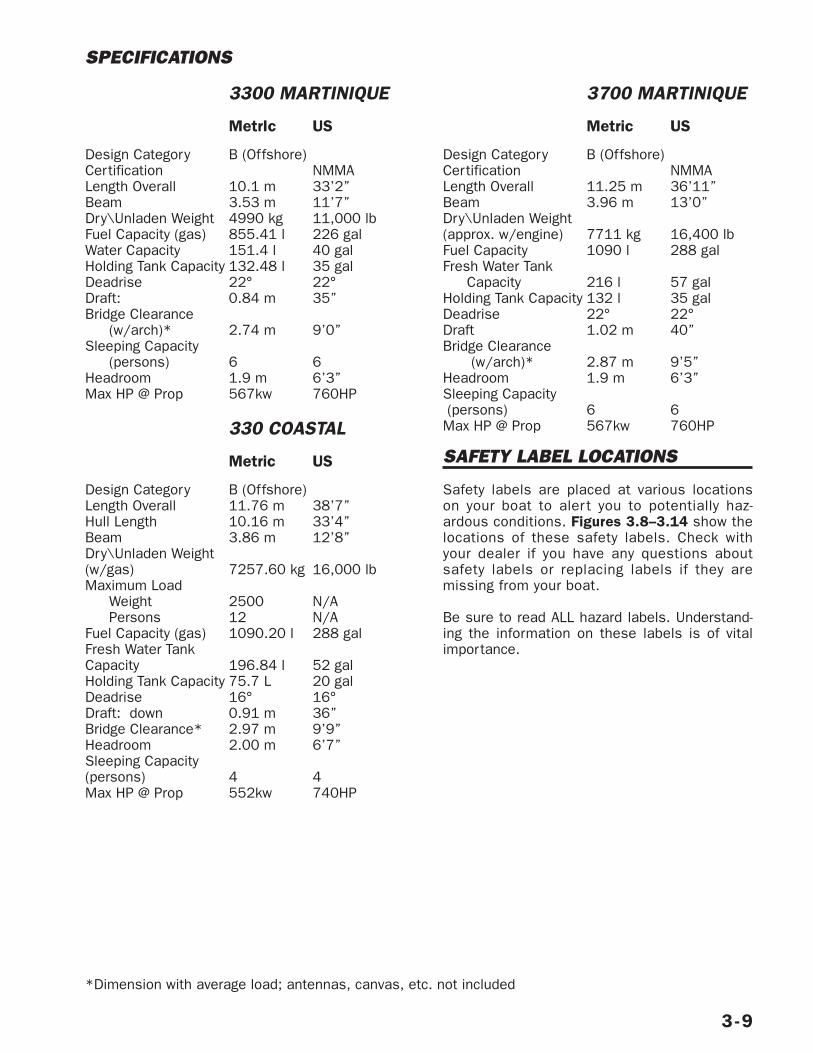
3-9
SPECIFICATIONS
3300 MARTINIQUE
MetrIc US
Design Category B (Offshore)Certification NMMALength Overall 10.1 m 33’2”Beam 3.53 m 11’7”Dry\Unladen Weight 4990 kg 11,000 lbFuel Capacity (gas) 855.41 l 226 galWater Capacity 151.4 l 40 galHolding Tank Capacity 132.48 l 35 galDeadrise 22° 22°Draft: 0.84 m 35”Bridge Clearance
(w/arch)* 2.74 m 9’0”Sleeping Capacity
(persons) 6 6Headroom 1.9 m 6’3”Max HP @ Prop 567kw 760HP
330 COASTAL
Metric US
Design Category B (Offshore)Length Overall 11.76 m 38’7”Hull Length 10.16 m 33’4”Beam 3.86 m 12’8”Dry\Unladen Weight(w/gas) 7257.60 kg 16,000 lbMaximum Load
Weight 2500 N/APersons 12 N/A
Fuel Capacity (gas) 1090.20 l 288 galFresh Water TankCapacity 196.84 l 52 galHolding Tank Capacity 75.7 L 20 galDeadrise 16° 16°Draft: down 0.91 m 36”Bridge Clearance* 2.97 m 9’9”Headroom 2.00 m 6’7”Sleeping Capacity(persons) 4 4Max HP @ Prop 552kw 740HP
3700 MARTINIQUE
Metric US
Design Category B (Offshore)Certification NMMALength Overall 11.25 m 36’11”Beam 3.96 m 13’0”Dry\Unladen Weight(approx. w/engine) 7711 kg 16,400 lbFuel Capacity 1090 l 288 galFresh Water Tank
Capacity 216 l 57 galHolding Tank Capacity 132 l 35 galDeadrise 22° 22°Draft 1.02 m 40”Bridge Clearance
(w/arch)* 2.87 m 9’5”Headroom 1.9 m 6’3”Sleeping Capacity(persons) 6 6Max HP @ Prop 567kw 760HP
SAFETY LABEL LOCATIONS
Safety labels are placed at various locationson your boat to aler t you to potentially haz-ardous conditions. Figures 3.8–3.14 show thelocations of these safety labels. Check withyour dealer if you have any questions aboutsafety labels or replacing labels if they aremissing from your boat.
Be sure to read ALL hazard labels. Understand-ing the information on these labels is of vitalimportance.
*Dimension with average load; antennas, canvas, etc. not included
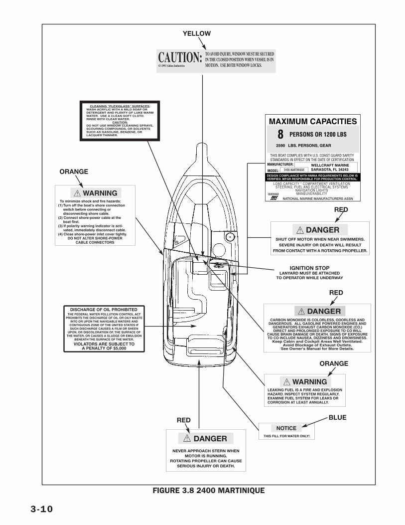
3-10
FIGURE 3.8 2400 MARTINIQUE
CAUTION:© 1993 Aldon Industries
TO AVOID INJURY, WINDOW MUST BE SECUREDIN THE CLOSED POSITION WHEN VESSEL IS INMOTION. USE BOTH WINDOW LOCKS.
! To minimize shock and fire hazards:(1) Turn off the boat's shore connection switch before connecting or disconnecting shore cable.(2) Connect shore-power cable at the boat first.(3) If polarity warning indicator is acti- vated, immediately disconnect cable.(4) Close shore-power inlet cover tightly.
DO NOT ALTER SHORE-POWERCABLE CONNECTORS
WARNING
MAXIMUM CAPACITIES
THIS BOAT COMPLIES WITH U.S. COAST GUARD SAFETYSTANDARDS IN EFFECT ON THE DATE OF CERTIFICATION
MANUFACTURER:
MODEL:WELLCRAFT MARINESARASOTA, FL 34243
8 PERSONS OR 1200 LBS
2590 LBS. PERSONS, GEAR
CERTIFIED
LOAD CAPACITY * COMPARTMENT VENTILATIONSTEERING, FUEL AND ELECTRICAL SYSTEMS
NAVIGATION LIGHTSMANEUVERABILITY
NATIONAL MARINE MANUFACTURERS ASSN
DESIGN COMPLIANCE WITH NMMA REQUIREMENTS BELOW ISVERIFIED. MFGR RESPONSIBLE FOR PRODUCTION CONTROL.
2400 MARTINIQUE
!SHUT OFF MOTOR WHEN NEAR SWIMMERS.
SEVERE INJURY OR DEATH WILL RESULTFROM CONTACT WITH A ROTATING PROPELLER.
DANGER
!CARBON MONOXIDE IS COLORLESS, ODORLESS AND
DANGEROUS. ALL GASOLINE POWERED ENGINES ANDGENERATORS EXHAUST CARBON MONOXIDE (CO.)DIRECT AND PROLONGED EXPOSURE TO CO WILL
CAUSE BRAIN DAMAGE OR DEATH. SIGNS OF EXPOSURETO CO INCLUDE NAUSEA, DIZZINESS AND DROWSINESS.
Keep Cabin and Cockpit Areas Well Ventilated.Avoid Blockage of Exhaust Outlets.
See Owner's Manual for More Details.
DANGER
!LEAKING FUEL IS A FIRE AND EXPLOSIONHAZARD. INSPECT SYSTEM REGULARLY.EXAMINE FUEL SYSTEM FOR LEAKS ORCORROSION AT LEAST ANNUALLY.
WARNING
IGNITION STOPLANYARD MUST BE ATTACHED
TO OPERATOR WHILE UNDERWAY
THIS FILL FOR WATER ONLY!
NOTICE
!
NEVER APPROACH STERN WHENMOTOR IS RUNNING.
ROTATING PROPELLER CAN CAUSESERIOUS INJURY OR DEATH.
DANGER
THE FEDERAL WATER POLLUTION CONTROL ACTPROHIBITS THE DISCHARGE OF OIL OR OILY WASTE
INTO OR UPON THE NAVIGABLE WATERS ANDCONTIGUOUS ZONE OF THE UNITED STATES IFSUCH DISCHARGE CAUSES A FILM OR SHEEN
UPON, OR DISCOLORATION OF, THE SURFACE OFTHE WATER, OR CAUSES A SLUDGE OR EMULSION
BENEATH THE SURFACE OF THE WATER.
DISCHARGE OF OIL PROHIBITED
VIOLATORS ARE SUBJECT TOA PENALTY OF $5,000
ORANGE
YELLOW
RED
ORANGE
BLUERED
RED
CLEANING "PLEXIGLASS" SURFACES:WASH ACRYLIC WITH A MILD SOAP ORDETERGENT AND PLENTY OF LUKE WARMWATER. USE A CLEAN SOFT CLOTH.RINSE WITH CLEAR WATER.
CAUTION:DO NOT USE WINDOW CLEANING SPRAYS,SCOURING COMPOUNDS, OR SOLVENTSSUCH AS GASOLINE, BENZENE, ORLACQUER THINNER.
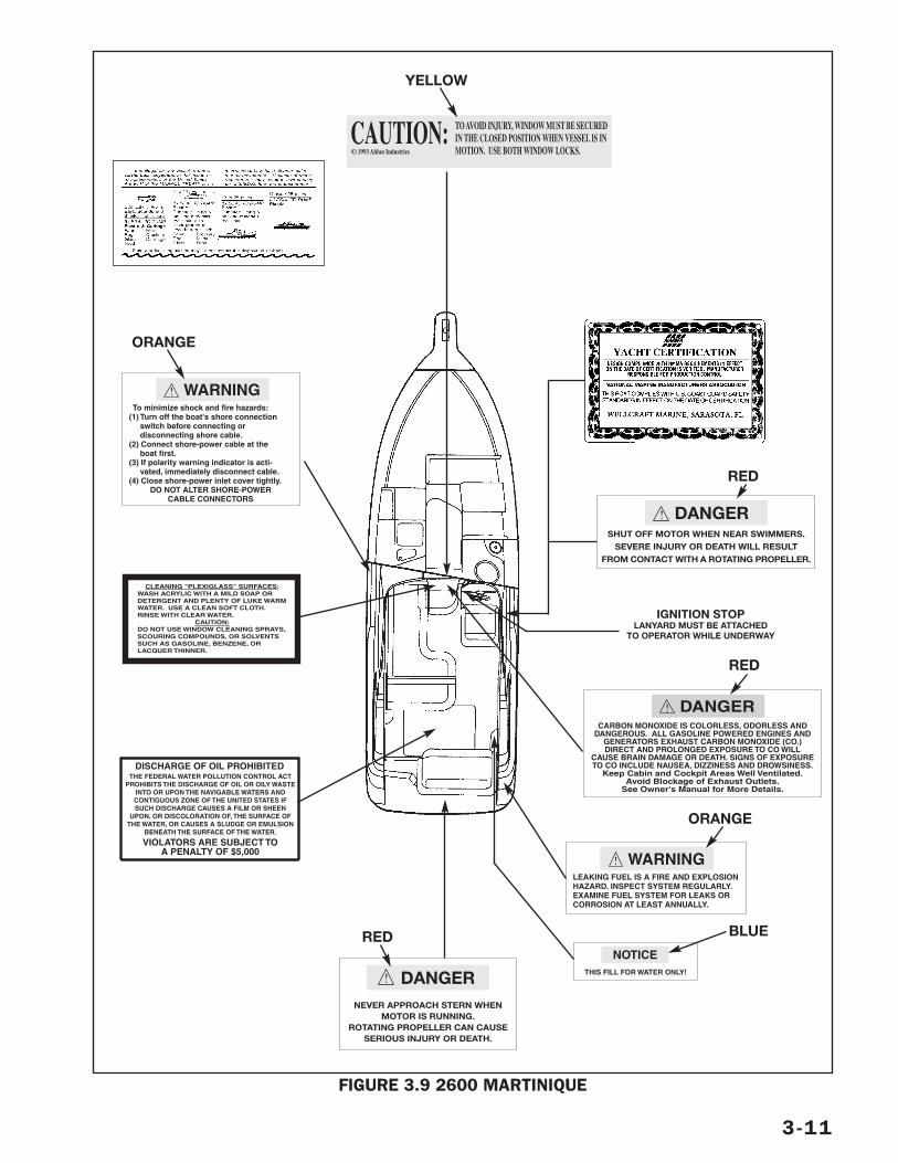
3-11
FIGURE 3.9 2600 MARTINIQUE
CAUTION:© 1993 Aldon Industries
TO AVOID INJURY, WINDOW MUST BE SECUREDIN THE CLOSED POSITION WHEN VESSEL IS INMOTION. USE BOTH WINDOW LOCKS.
! To minimize shock and fire hazards:(1) Turn off the boat's shore connection switch before connecting or disconnecting shore cable.(2) Connect shore-power cable at the boat first.(3) If polarity warning indicator is acti- vated, immediately disconnect cable.(4) Close shore-power inlet cover tightly.
DO NOT ALTER SHORE-POWERCABLE CONNECTORS
WARNING
!SHUT OFF MOTOR WHEN NEAR SWIMMERS.
SEVERE INJURY OR DEATH WILL RESULTFROM CONTACT WITH A ROTATING PROPELLER.
DANGER
!CARBON MONOXIDE IS COLORLESS, ODORLESS AND
DANGEROUS. ALL GASOLINE POWERED ENGINES ANDGENERATORS EXHAUST CARBON MONOXIDE (CO.)DIRECT AND PROLONGED EXPOSURE TO CO WILL
CAUSE BRAIN DAMAGE OR DEATH. SIGNS OF EXPOSURETO CO INCLUDE NAUSEA, DIZZINESS AND DROWSINESS.
Keep Cabin and Cockpit Areas Well Ventilated.Avoid Blockage of Exhaust Outlets.
See Owner's Manual for More Details.
DANGER
!LEAKING FUEL IS A FIRE AND EXPLOSIONHAZARD. INSPECT SYSTEM REGULARLY.EXAMINE FUEL SYSTEM FOR LEAKS ORCORROSION AT LEAST ANNUALLY.
WARNING
IGNITION STOPLANYARD MUST BE ATTACHED
TO OPERATOR WHILE UNDERWAY
THIS FILL FOR WATER ONLY!
NOTICE
!
NEVER APPROACH STERN WHENMOTOR IS RUNNING.
ROTATING PROPELLER CAN CAUSESERIOUS INJURY OR DEATH.
DANGER
THE FEDERAL WATER POLLUTION CONTROL ACTPROHIBITS THE DISCHARGE OF OIL OR OILY WASTE
INTO OR UPON THE NAVIGABLE WATERS ANDCONTIGUOUS ZONE OF THE UNITED STATES IFSUCH DISCHARGE CAUSES A FILM OR SHEEN
UPON, OR DISCOLORATION OF, THE SURFACE OFTHE WATER, OR CAUSES A SLUDGE OR EMULSION
BENEATH THE SURFACE OF THE WATER.
DISCHARGE OF OIL PROHIBITED
VIOLATORS ARE SUBJECT TOA PENALTY OF $5,000
ORANGE
YELLOW
RED
RED
ORANGE
BLUERED
CLEANING "PLEXIGLASS" SURFACES:WASH ACRYLIC WITH A MILD SOAP ORDETERGENT AND PLENTY OF LUKE WARMWATER. USE A CLEAN SOFT CLOTH.RINSE WITH CLEAR WATER.
CAUTION:DO NOT USE WINDOW CLEANING SPRAYS,SCOURING COMPOUNDS, OR SOLVENTSSUCH AS GASOLINE, BENZENE, ORLACQUER THINNER.
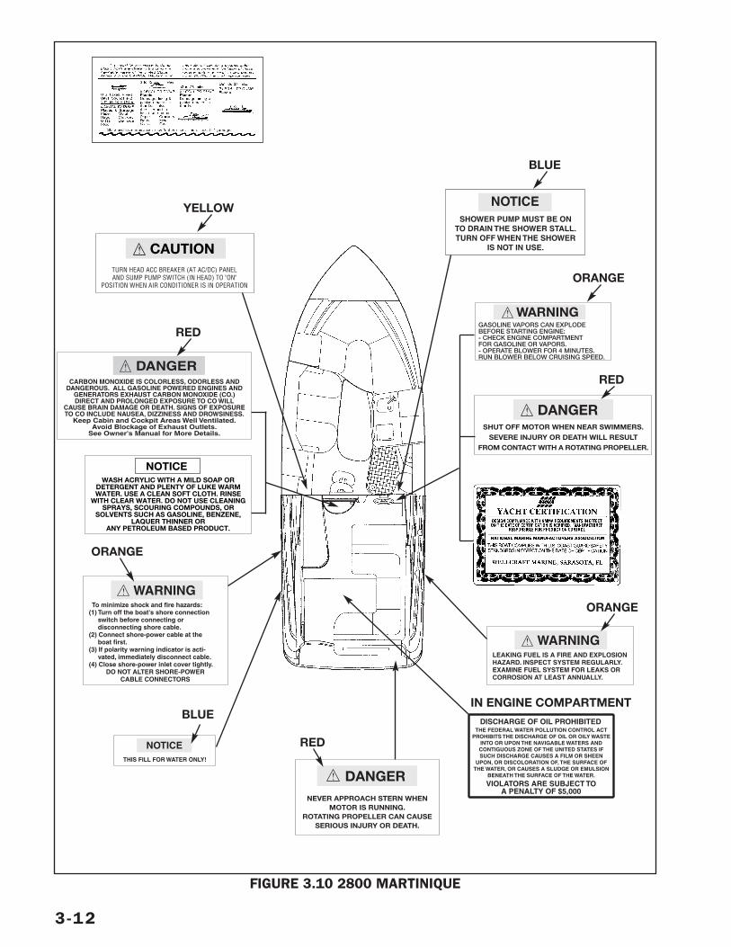
3-12
FIGURE 3.10 2800 MARTINIQUE
! CAUTIONTURN HEAD ACC BREAKER (AT AC/DC) PANELAND SUMP PUMP SWITCH (IN HEAD) TO "ON"
POSITION WHEN AIR CONDITIONER IS IN OPERATION
SHOWER PUMP MUST BE ONTO DRAIN THE SHOWER STALL.TURN OFF WHEN THE SHOWER
IS NOT IN USE.
NOTICE
THE FEDERAL WATER POLLUTION CONTROL ACTPROHIBITS THE DISCHARGE OF OIL OR OILY WASTE
INTO OR UPON THE NAVIGABLE WATERS ANDCONTIGUOUS ZONE OF THE UNITED STATES IFSUCH DISCHARGE CAUSES A FILM OR SHEEN
UPON, OR DISCOLORATION OF, THE SURFACE OFTHE WATER, OR CAUSES A SLUDGE OR EMULSION
BENEATH THE SURFACE OF THE WATER.
DISCHARGE OF OIL PROHIBITED
VIOLATORS ARE SUBJECT TOA PENALTY OF $5,000
IN ENGINE COMPARTMENT
!CARBON MONOXIDE IS COLORLESS, ODORLESS AND
DANGEROUS. ALL GASOLINE POWERED ENGINES ANDGENERATORS EXHAUST CARBON MONOXIDE (CO.)DIRECT AND PROLONGED EXPOSURE TO CO WILL
CAUSE BRAIN DAMAGE OR DEATH. SIGNS OF EXPOSURETO CO INCLUDE NAUSEA, DIZZINESS AND DROWSINESS.
Keep Cabin and Cockpit Areas Well Ventilated.Avoid Blockage of Exhaust Outlets.
See Owner's Manual for More Details.
DANGER
RED
NOTICEWASH ACRYLIC WITH A MILD SOAP OR
DETERGENT AND PLENTY OF LUKE WARMWATER. USE A CLEAN SOFT CLOTH. RINSE
WITH CLEAR WATER. DO NOT USE CLEANINGSPRAYS, SCOURING COMPOUNDS, OR
SOLVENTS SUCH AS GASOLINE, BENZENE,LAQUER THINNER OR
ANY PETROLEUM BASED PRODUCT.
! To minimize shock and fire hazards:(1) Turn off the boat's shore connection switch before connecting or disconnecting shore cable.(2) Connect shore-power cable at the boat first.(3) If polarity warning indicator is acti- vated, immediately disconnect cable.(4) Close shore-power inlet cover tightly.
DO NOT ALTER SHORE-POWERCABLE CONNECTORS
WARNING
ORANGE
THIS FILL FOR WATER ONLY!
NOTICE
BLUE
!
NEVER APPROACH STERN WHENMOTOR IS RUNNING.
ROTATING PROPELLER CAN CAUSESERIOUS INJURY OR DEATH.
DANGER
RED
!LEAKING FUEL IS A FIRE AND EXPLOSIONHAZARD. INSPECT SYSTEM REGULARLY.EXAMINE FUEL SYSTEM FOR LEAKS ORCORROSION AT LEAST ANNUALLY.
WARNING
ORANGE
!SHUT OFF MOTOR WHEN NEAR SWIMMERS.
SEVERE INJURY OR DEATH WILL RESULTFROM CONTACT WITH A ROTATING PROPELLER.
DANGER
RED
!GASOLINE VAPORS CAN EXPLODEBEFORE STARTING ENGINE:- CHECK ENGINE COMPARTMENTFOR GASOLINE OR VAPORS.- OPERATE BLOWER FOR 4 MINUTES.RUN BLOWER BELOW CRUISING SPEED.
WARNING
ORANGE
BLUE
YELLOW
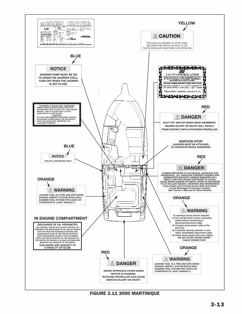
3-133-13
FIGURE 3.11 3000 MARTINIQUE
!SHUT OFF MOTOR WHEN NEAR SWIMMERS.
SEVERE INJURY OR DEATH WILL RESULTFROM CONTACT WITH A ROTATING PROPELLER.
DANGER
!CARBON MONOXIDE IS COLORLESS, ODORLESS AND
DANGEROUS. ALL GASOLINE POWERED ENGINES ANDGENERATORS EXHAUST CARBON MONOXIDE (CO.)DIRECT AND PROLONGED EXPOSURE TO CO WILL
CAUSE BRAIN DAMAGE OR DEATH. SIGNS OF EXPOSURETO CO INCLUDE NAUSEA, DIZZINESS AND DROWSINESS.
Keep Cabin and Cockpit Areas Well Ventilated.Avoid Blockage of Exhaust Outlets.
See Owner's Manual for More Details.
DANGER
RED
RED
! To minimize shock and fire hazards:(1) Turn off the boat's shore connection switch before connecting or disconnecting shore cable.(2) Connect shore-power cable at the boat first.(3) If polarity warning indicator is acti- vated, immediately disconnect cable.(4) Close shore-power inlet cover tightly.
DO NOT ALTER SHORE-POWERCABLE CONNECTORS
WARNING
ORANGE
!LEAKING FUEL IS A FIRE AND EXPLOSIONHAZARD. INSPECT SYSTEM REGULARLY.EXAMINE FUEL SYSTEM FOR LEAKS ORCORROSION AT LEAST ANNUALLY.
WARNING
ORANGE
CLEANING "PLEXIGLASS" SURFACES:WASH ACRYLIC WITH A MILD SOAP ORDETERGENT AND PLENTY OF LUKE WARMWATER. USE A CLEAN SOFT CLOTH.RINSE WITH CLEAR WATER.
CAUTION:DO NOT USE WINDOW CLEANING SPRAYS,SCOURING COMPOUNDS, OR SOLVENTSSUCH AS GASOLINE, BENZENE, ORLACQUER THINNER.
THE FEDERAL WATER POLLUTION CONTROL ACTPROHIBITS THE DISCHARGE OF OIL OR OILY WASTE
INTO OR UPON THE NAVIGABLE WATERS ANDCONTIGUOUS ZONE OF THE UNITED STATES IFSUCH DISCHARGE CAUSES A FILM OR SHEEN
UPON, OR DISCOLORATION OF, THE SURFACE OFTHE WATER, OR CAUSES A SLUDGE OR EMULSION
BENEATH THE SURFACE OF THE WATER.
DISCHARGE OF OIL PROHIBITED
VIOLATORS ARE SUBJECT TOA PENALTY OF $5,000
IN ENGINE COMPARTMENT
IGNITION STOPLANYARD MUST BE ATTACHED
TO OPERATOR WHILE UNDERWAY
!
NEVER APPROACH STERN WHENMOTOR IS RUNNING.
ROTATING PROPELLER CAN CAUSESERIOUS INJURY OR DEATH.
DANGER
RED
THIS FILL FOR WATER ONLY!
NOTICE
BLUE
!LEAKING FUEL IS A FIRE AND EXPLOSIONHAZARD. INSPECT SYSTEM REGULARLY.EXAMINE FUEL SYSTEM FOR LEAKS ORCORROSION AT LEAST ANNUALLY.
WARNING
ORANGE
SHOWER PUMP MUST BE ONTO DRAIN THE SHOWER STALL.TURN OFF WHEN THE SHOWER
IS NOT IN USE.
NOTICE
! CAUTIONTURN HEAD ACC BREAKER (AT AC/DC) PANELAND SUMP PUMP SWITCH (IN HEAD) TO "ON"
POSITION WHEN AIR CONDITIONER IS IN OPERATION
YELLOW
BLUE
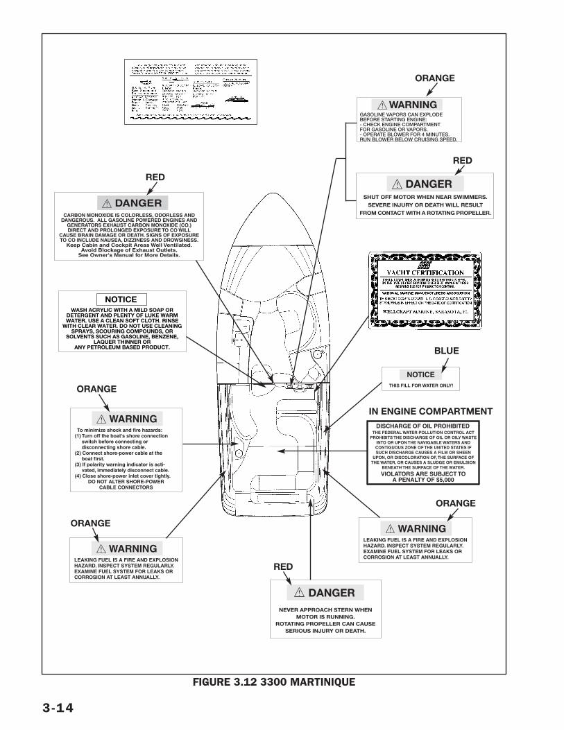
3-14
FIGURE 3.12 3300 MARTINIQUE
!SHUT OFF MOTOR WHEN NEAR SWIMMERS.
SEVERE INJURY OR DEATH WILL RESULTFROM CONTACT WITH A ROTATING PROPELLER.
DANGER
!CARBON MONOXIDE IS COLORLESS, ODORLESS AND
DANGEROUS. ALL GASOLINE POWERED ENGINES ANDGENERATORS EXHAUST CARBON MONOXIDE (CO.)DIRECT AND PROLONGED EXPOSURE TO CO WILL
CAUSE BRAIN DAMAGE OR DEATH. SIGNS OF EXPOSURETO CO INCLUDE NAUSEA, DIZZINESS AND DROWSINESS.
Keep Cabin and Cockpit Areas Well Ventilated.Avoid Blockage of Exhaust Outlets.
See Owner's Manual for More Details.
DANGER
!LEAKING FUEL IS A FIRE AND EXPLOSIONHAZARD. INSPECT SYSTEM REGULARLY.EXAMINE FUEL SYSTEM FOR LEAKS ORCORROSION AT LEAST ANNUALLY.
WARNING
RED
RED
ORANGE
! To minimize shock and fire hazards:(1) Turn off the boat's shore connection switch before connecting or disconnecting shore cable.(2) Connect shore-power cable at the boat first.(3) If polarity warning indicator is acti- vated, immediately disconnect cable.(4) Close shore-power inlet cover tightly.
DO NOT ALTER SHORE-POWERCABLE CONNECTORS
WARNING
ORANGE
!LEAKING FUEL IS A FIRE AND EXPLOSIONHAZARD. INSPECT SYSTEM REGULARLY.EXAMINE FUEL SYSTEM FOR LEAKS ORCORROSION AT LEAST ANNUALLY.
WARNING
ORANGE
THE FEDERAL WATER POLLUTION CONTROL ACTPROHIBITS THE DISCHARGE OF OIL OR OILY WASTE
INTO OR UPON THE NAVIGABLE WATERS ANDCONTIGUOUS ZONE OF THE UNITED STATES IFSUCH DISCHARGE CAUSES A FILM OR SHEEN
UPON, OR DISCOLORATION OF, THE SURFACE OFTHE WATER, OR CAUSES A SLUDGE OR EMULSION
BENEATH THE SURFACE OF THE WATER.
DISCHARGE OF OIL PROHIBITED
VIOLATORS ARE SUBJECT TOA PENALTY OF $5,000
IN ENGINE COMPARTMENT
!
NEVER APPROACH STERN WHENMOTOR IS RUNNING.
ROTATING PROPELLER CAN CAUSESERIOUS INJURY OR DEATH.
DANGER
RED
THIS FILL FOR WATER ONLY!
NOTICE
BLUE
!GASOLINE VAPORS CAN EXPLODEBEFORE STARTING ENGINE:- CHECK ENGINE COMPARTMENTFOR GASOLINE OR VAPORS.- OPERATE BLOWER FOR 4 MINUTES.RUN BLOWER BELOW CRUISING SPEED.
WARNING
NOTICEWASH ACRYLIC WITH A MILD SOAP OR
DETERGENT AND PLENTY OF LUKE WARMWATER. USE A CLEAN SOFT CLOTH. RINSE
WITH CLEAR WATER. DO NOT USE CLEANINGSPRAYS, SCOURING COMPOUNDS, OR
SOLVENTS SUCH AS GASOLINE, BENZENE,LAQUER THINNER OR
ANY PETROLEUM BASED PRODUCT.
ORANGE
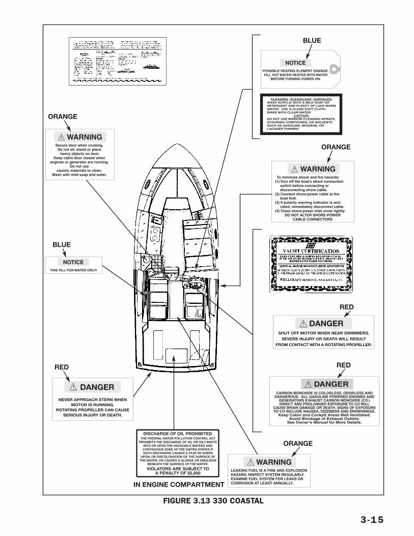
3-15
FIGURE 3.13 330 COASTAL
!SHUT OFF MOTOR WHEN NEAR SWIMMERS.
SEVERE INJURY OR DEATH WILL RESULTFROM CONTACT WITH A ROTATING PROPELLER.
DANGER
!CARBON MONOXIDE IS COLORLESS, ODORLESS AND
DANGEROUS. ALL GASOLINE POWERED ENGINES ANDGENERATORS EXHAUST CARBON MONOXIDE (CO.)DIRECT AND PROLONGED EXPOSURE TO CO WILL
CAUSE BRAIN DAMAGE OR DEATH. SIGNS OF EXPOSURETO CO INCLUDE NAUSEA, DIZZINESS AND DROWSINESS.
Keep Cabin and Cockpit Areas Well Ventilated.Avoid Blockage of Exhaust Outlets.
See Owner's Manual for More Details.
DANGER
RED
RED
POSSIBLE HEATING ELEMENT DAMAGE.FILL HOT WATER HEATER WITH WATER
BEFORE TURNING POWER ON.
NOTICE
CLEANING "PLEXIGLASS" SURFACES:WASH ACRYLIC WITH A MILD SOAP ORDETERGENT AND PLENTY OF LUKE WARMWATER. USE A CLEAN SOFT CLOTH.RINSE WITH CLEAR WATER.
CAUTION:DO NOT USE WINDOW CLEANING SPRAYS,SCOURING COMPOUNDS, OR SOLVENTSSUCH AS GASOLINE, BENZENE, ORLACQUER THINNER.
BLUE
!LEAKING FUEL IS A FIRE AND EXPLOSIONHAZARD. INSPECT SYSTEM REGULARLY.EXAMINE FUEL SYSTEM FOR LEAKS ORCORROSION AT LEAST ANNUALLY.
WARNING
ORANGE
!
NEVER APPROACH STERN WHENMOTOR IS RUNNING.
ROTATING PROPELLER CAN CAUSESERIOUS INJURY OR DEATH.
DANGER
RED
! To minimize shock and fire hazards:(1) Turn off the boat's shore connection switch before connecting or disconnecting shore cable.(2) Connect shore-power cable at the boat first.(3) If polarity warning indicator is acti- vated, immediately disconnect cable.(4) Close shore-power inlet cover tightly.
DO NOT ALTER SHORE-POWERCABLE CONNECTORS
WARNING
ORANGE
THIS FILL FOR WATER ONLY!
NOTICE
BLUE
!Secure door when cruising.
Do not sit, stand or place heavy objects on door.
Keep cabin door closed whenengines or generator are running.
Do not usecaustic materials to clean.
Wash with mild soap and water.
WARNING
THE FEDERAL WATER POLLUTION CONTROL ACTPROHIBITS THE DISCHARGE OF OIL OR OILY WASTE
INTO OR UPON THE NAVIGABLE WATERS ANDCONTIGUOUS ZONE OF THE UNITED STATES IFSUCH DISCHARGE CAUSES A FILM OR SHEEN
UPON, OR DISCOLORATION OF, THE SURFACE OFTHE WATER, OR CAUSES A SLUDGE OR EMULSION
BENEATH THE SURFACE OF THE WATER.
DISCHARGE OF OIL PROHIBITED
VIOLATORS ARE SUBJECT TOA PENALTY OF $5,000
IN ENGINE COMPARTMENT
ORANGE
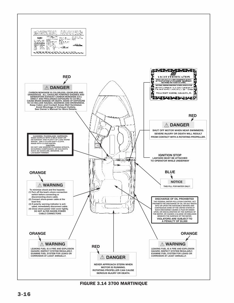
3-16
FIGURE 3.14 3700 MARTINIQUE
!SHUT OFF MOTOR WHEN NEAR SWIMMERS.
SEVERE INJURY OR DEATH WILL RESULTFROM CONTACT WITH A ROTATING PROPELLER.
DANGER
!CARBON MONOXIDE IS COLORLESS, ODORLESS AND
DANGEROUS. ALL GASOLINE POWERED ENGINES ANDGENERATORS EXHAUST CARBON MONOXIDE (CO.)DIRECT AND PROLONGED EXPOSURE TO CO WILL
CAUSE BRAIN DAMAGE OR DEATH. SIGNS OF EXPOSURETO CO INCLUDE NAUSEA, DIZZINESS AND DROWSINESS.
Keep Cabin and Cockpit Areas Well Ventilated.Avoid Blockage of Exhaust Outlets.
See Owner's Manual for More Details.
DANGER
RED
RED
!
NEVER APPROACH STERN WHENMOTOR IS RUNNING.
ROTATING PROPELLER CAN CAUSESERIOUS INJURY OR DEATH.
DANGER
RED !LEAKING FUEL IS A FIRE AND EXPLOSIONHAZARD. INSPECT SYSTEM REGULARLY.EXAMINE FUEL SYSTEM FOR LEAKS ORCORROSION AT LEAST ANNUALLY.
WARNING
ORANGE
!LEAKING FUEL IS A FIRE AND EXPLOSIONHAZARD. INSPECT SYSTEM REGULARLY.EXAMINE FUEL SYSTEM FOR LEAKS ORCORROSION AT LEAST ANNUALLY.
WARNING
ORANGE
CLEANING "PLEXIGLASS" SURFACES:WASH ACRYLIC WITH A MILD SOAP ORDETERGENT AND PLENTY OF LUKE WARMWATER. USE A CLEAN SOFT CLOTH.RINSE WITH CLEAR WATER.
CAUTION:DO NOT USE WINDOW CLEANING SPRAYS,SCOURING COMPOUNDS, OR SOLVENTSSUCH AS GASOLINE, BENZENE, ORLACQUER THINNER.
THE FEDERAL WATER POLLUTION CONTROL ACTPROHIBITS THE DISCHARGE OF OIL OR OILY WASTE
INTO OR UPON THE NAVIGABLE WATERS ANDCONTIGUOUS ZONE OF THE UNITED STATES IFSUCH DISCHARGE CAUSES A FILM OR SHEEN
UPON, OR DISCOLORATION OF, THE SURFACE OFTHE WATER, OR CAUSES A SLUDGE OR EMULSION
BENEATH THE SURFACE OF THE WATER.
DISCHARGE OF OIL PROHIBITED
VIOLATORS ARE SUBJECT TOA PENALTY OF $5,000
! To minimize shock and fire hazards:(1) Turn off the boat's shore connection switch before connecting or disconnecting shore cable.(2) Connect shore-power cable at the boat first.(3) If polarity warning indicator is acti- vated, immediately disconnect cable.(4) Close shore-power inlet cover tightly.
DO NOT ALTER SHORE-POWERCABLE CONNECTORS
WARNING
ORANGE
THIS FILL FOR WATER ONLY!
NOTICE
BLUE
IGNITION STOPLANYARD MUST BE ATTACHED
TO OPERATOR WHILE UNDERWAY

This section describes the fresh water, waste,and bilge systems on your cruiser. Some modelsmay also be equipped with a raw water system.
FRESH WATER SYSTEM
The fresh water system on your cruiser consistsof a water tank, pump, water heater, and a dis-tribution system. Fresh water is supplied tovarious areas including the galley, the head, anda transom shower. Some models have malehose connections for cockpit and foredeckwashdown. Figure 4.1 shows a typical freshwater system. Some components are optionalequipment. Check with your dealer if you have aquestion about your cruiser’s system.
FRESH WATER TANKThe fresh water system has a water tank in theaft section of the boat. The tank has a separatefiller on the gunwale. A water tank vent is nextto the fill plate.
To fill the fresh water tank:
1. Make sure the dockside water supply is suitablefor drinking. Not all dockside water is drinkingwater. Check with the dockmaster if necessary.
2. Insert the filler cap key provided with yourboat into the slot on the filler cap and turncounterclockwise to unlock. Remove thefiller cap.
3. Using the hose from the dockside watersupply, fill the tank until water flows out ofthe vent.
Note: Garden hoses are not recommendedfor filling the tank. See your dealer for a san-itary drinking water hose.
4. Close the fill fitting.
4-1
Water Systems – 4
HEAD SINK/SHOWER
VACUFLUSH
FILLVENT
FRESHWATERTANK
ENGINE HEATEXCHANGER
FILTER &PUMP
HOT WATER
TRANSOMSHOWER
COLD WATER
STERN BOW
GALLEYSINK
COCKPITWASHDOWN
ICE MAKER
WATERHEATER
COCKPITWET BAR
DOCKSIDEWATER
CONNECTION
FIGURE 4.1 TYPICAL COMPLEX FRESHWATER SYSTEM
FRESH WATER PUMPThe fresh water pump supplies water underpressure to the system when the docksidewater supply is not connected. The FRESHWATER PUMP breaker switch on the DC CON-TROL panel controls its operation. The pump isunder the engine hatch.
Before entering the pump, the water passesthrough a filter to capture any contaminants.When the breaker is switched to ON, the pumpruns until the hot and cold water systems arepressurized. An automatic pressure switchshuts the pump off until the pressure drops toa preset level (for example, a pressure dropcaused by opening a faucet). The pump will thenrun again until the system is pressurized andturn itself off.
If the pump runs from time to time even thoughno water is being used, a leak in a water line is alikely cause. Check all lines for a leak and repair.
Important: Operate the fresh water pump onlywhen there is water in the tank. Running thepump dry will damage the impeller. The pumpwill not automatically turn off when the tank isempty. If the breaker switch is left on when thetank is empty, the pump may overheat.
INITIAL STARTUP1. Fill the tank approximately 1/2 – 3/4 full.
Section 3, Specifications, lists the capacityof the water tank on your cruiser.
2. Turn the FRESH WATER PUMP switch on.
3. Open each cold water faucet, beginning withthe faucet furthest from the water tank, tolet air escape. Close the faucet when thewater flow becomes steady, and leave itclosed.
4. Open a hot water faucet to fill the waterheater and allow air to escape from the line.Close the faucet.
5. Open each hot water faucet, beginning withthe faucet furthest from the water heater, tolet air escape. Close the faucet when thewater flow becomes steady, and leave itclosed.
The pump will run until the system is pres-surized and then shut off.
6. Fill the tank to its capacity.
SANITIZING THE FRESHWATER SYSTEMBefore using your fresh water system for thefirst time or if you suspect the water systemhas been contaminated, do the following:
1. Drain the fresh water tank completely. Openall faucets, showers, and other outlets untilthe flow of water stops. Shut off the freshwater pump as soon as the tank is empty.
2. Mix a solution of 2 ounces householdbleach to 1 gallon of water for every 15 gal-lons of tank capacity. Pour the solution intothe fresh water tank.
3. Fill the tank with clean fresh water.
4. Turn the fresh water pump on and bleed airfrom all faucets, showers, and other outlets.
5. After 3 hours, drain the system completely.
6. Fill the tank with clean fresh water. Flushsystem by draining tank again.
7. Fill the tank with clean, fresh drinking water.
If you can smell or taste bleach in the water:
1. Drain the system completely.
2. Mix a solution of 1 quart white vinegar to 5gallons of water. Pour the solution into thefresh water tank.
3. Allow the solution to remain in the tank untilone hour of cruising time has been logged.The boat’s motion will wash down the tankwith the vinegar/water solution and neutral-ize the bleach.
4. Drain the fresh water system completely.
5. Flush the system with one full tank of water.
6. Fill the tank with clean fresh drinking water.
DOCKSIDE WATER HOOKUPAs an alternative to the fresh water tank, thesystem can be connected to a dockside watersupply. Because the water enters the boat underpressure, it bypasses the fresh water tank, filterand pump. The pump should be shut off whenthe system is connected to dockside water.
4-2
NOTE: Using dockside water does not replenishwater supply in your tank. The tank can only befilled at the fresh water fill plate.
The fresh water system operates at a lowerpressure than that supplied from a docksidewater source. Unless the pressure is regulated,dockside water may rupture lines or leakthrough gaskets. Monitor the water systemcarefully the first time you hook it up to thedockside water system because the system isconnected to an unlimited supply of water. Thedockside water inlet on your cruiser may beequipped with a pressure regulator to reducethe pressure of the water supplied to yourboat’s system. Check with your dealer if youhave a question.
To connect dockside water:
1. Turn the FRESH WATER PUMP switch off.
2. Remove the threaded plug from the femaleswivel hose connector of the water inlet fit-ting. Be sure to clean both ends and flushthe hose before connecting. Foreign mattermay damage the pressure regulator.
3 Attach the proper sanitary drinking waterhose to the water inlet fitting.
4. Before connecting the dockside water out-let, open the valve fully to flush away anyrust particles which may be present.
5. Connect the hose to the dockside water outlet.
WATER HEATERYour boat is equipped with a water heater to pro-vide hot water to the fresh water system. Abreaker marked WATER HEATER on the AC controlpanel controls the operation of the heater. Theheater will not operate using DC power. Somemodels may have an adjustable thermostat toregulate hot water temperature. Check with yourdealer for the capacity of the water heater.
Important: Before turning the water heater cir-cuit breaker ON, make sure the water heater isfull of water. Turning on power to an emptyheater could damage the heating elements andmake the water heater useless.
Follow these procedures to use the water heater:
1. Make sure the water heater is full of waterby opening a hot water faucet until a steadystream of water flows out of the faucet andall air is removed from the hot water lines.
2. With the generator running or shore powerconnected to your boat, switch on theWATER HEATER circuit breaker at the ACCONTROL panel.
3. Wait for the water in the tank to heat up;then use as you would at home.
HEAT EXCHANGERIf your boat is equipped with a heat exchanger,heat from the engine is used to heat water inthe heater. Water in the heater is heated when-ever the engine is running. On twin engineboats, the heat exchanger is normally on thestarboard engine.
NEVER leave the boat unattendedwhile using the dockside waterhookup. If a line ruptures or othermajor leak develops, excess water inthe bilge could damage the engines orother boat components, or — worseyet — the excess water could sinkyour boat. Turn the water supply offbefore leaving.
CAUTION!
4-3
Before connecting to any water fittingbe sure the water is potable and suit-able for human consumption. Also, aspecial sanitary drinking water hose isrequired for the potable water connec-tion. Do not use a common gardenhose for drinking water.
WARNING!
This water may be very hot, especiallyafter the engines have been runningfor several hours. Be sure to check thetemperature of the water before usingwater from the heater.
WARNING!
RAW WATER SYSTEM
A raw water system is provided as optionalequipment on some models. The raw waterpump switch is at the helm. The pump locationvaries by model. The raw water system hasmale hose connections for washing down thecockpit and foredeck. If the raw water hose noz-zle is closed, the pump will stop working whenthe hose is pressurized and start working againwhen the nozzle is opened.
SEACOCKS
Your boat is equipped with seacocks to shut offopenings below the water line in emergencies orwhen removing various components for repair.Close seacocks when your boat will be unat-tended for extended periods of time.
A sea strainer installed on the intake side of thewater cooling system protects the system fromclogging and provides an easy way to remove occa-sional debris (Figure 4.2). Periodic inspection andremoval of debris is essential for effective opera-tion, but the frequency will vary depending on theamount of use and local conditions.
4-4
WATER SYSTEM TROUBLESHOOTING
PROBLEM
Air in system
Fresh water pump cycleson and off
No water at shower orsinks with faucets on
Low water pressure at allsinks and shower
Low water pressure at onesink
Raw water pump notpumping water
CAUSE
Water tank empty
Leak in water system
FRESH WATER PUMPbreaker off
Water tank empty
Blocked or pinched waterlines
Loose electrical connec-tions
Defective pump
Defective pump
Pinched water line
Tripped circuit breaker
No water supply
Loose electrical connec-tions
SOLUTION
Fill tank. With pump on, bleed air fromlines by opening faucets until water flowsout.
Locate leak and repair.
Switch breaker to ON.
Fill tank.
Clear obstruction or straighten line.
Check connections; tighten as needed.
See your dealer for service.
See your dealer for service.
See your dealer for service.
Straighten line.
Reset if tripped.
Check for clogged pump. Remove materialas needed.
Check for clogged thru–hull fitting. Cleanfitting.
Check and tighten connections. Makesure wires are not broken.
WASTE SYSTEM
All waste system components are made of mate-rials which prevent odor permeation and resistchemical actions. See manufacturer’s manualbefore adding chemicals to your waste system.
VACUFLUSH® HEADIf your boat is equipped with the VacuFlushhead, your waste system is actuated by a HEADor TOILET SYSTEM switch at the DC electricalpanel. It uses fresh water to minimize odorproblems. To add water to the bowl, raise flushlever until desired water level is reached. Adddeodorizer before use the head. The pedal atthe base of the head evacuates waste and avacuum forces the waste to the holding tank.Figure 4.3 is a diagram of a typical VacuFlushsystem.
To flush, press flush lever sharply to floor untilcontents clear bowl. A sharp popping noise isnormal when the vacuum seal is broken. Holdflush lever down for three seconds. If flush leveris accidentally released before waste clearsbowl, do not attempt to flush toilet again untilvacuum pump stops running. A small amount ofwater should remain in the bowl after flushing.Do not dispose of sanitar y napkins or otherinsoluble items in toilet.
Make sure all guests understand the operationof the VacuFlush system and that the instruc-tion label is easy to read and in plain sight.
Refer to your VacuFlush manual for completeinformation about the operation of the system.
HOLDING TANKWaste from the toilet is flushed to the holdingtank. You can empty the holding tank using adockside pumpout or, when permitted, througha macerator through hull fitting in the hull bot-tom.
4-5
Waste in the holding tank can formmethane, an explosive gas. Use suitableprecautions when any maintenance isdone to the sanitary system.
WARNING!
FIGURE 4.2 SEACOCK AND SEA STRAINER
FIGURE 4.3 TYPICAL VACUFLUSH SYSTEM
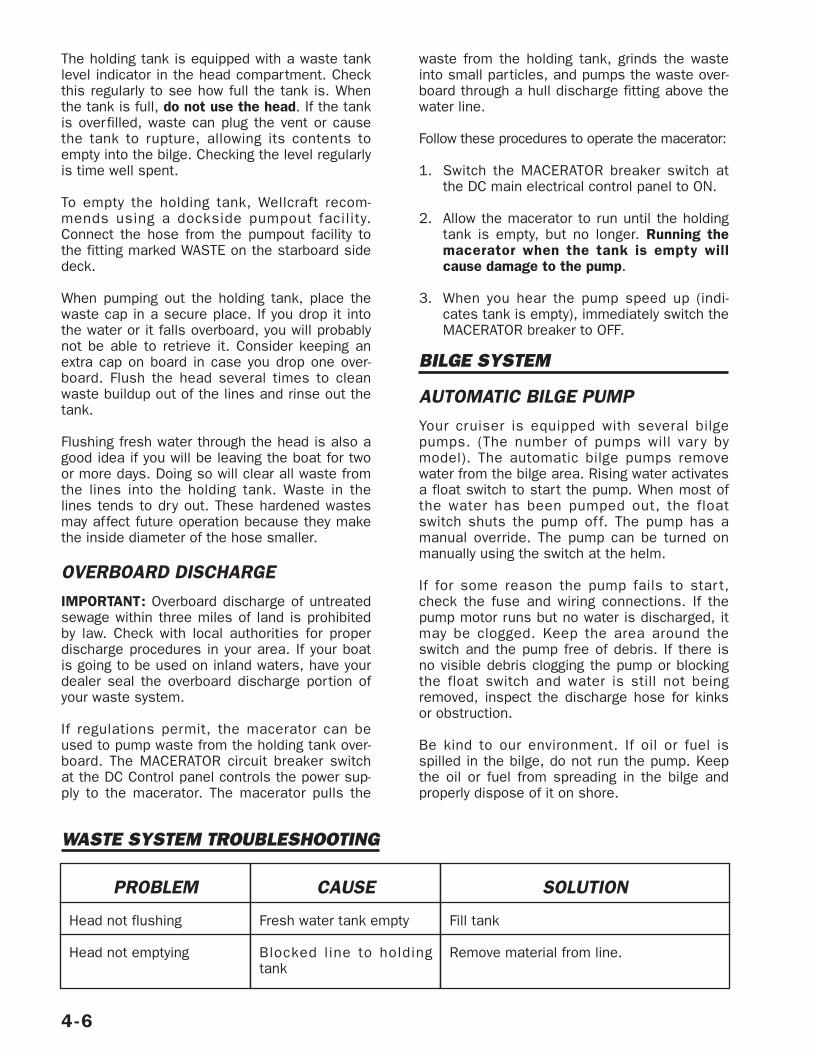
The holding tank is equipped with a waste tanklevel indicator in the head compartment. Checkthis regularly to see how full the tank is. Whenthe tank is full, do not use the head. If the tankis overfilled, waste can plug the vent or causethe tank to rupture, allowing its contents toempty into the bilge. Checking the level regularlyis time well spent.
To empty the holding tank, Wellcraft recom-mends using a dockside pumpout facility.Connect the hose from the pumpout facility tothe fitting marked WASTE on the starboard sidedeck.
When pumping out the holding tank, place thewaste cap in a secure place. If you drop it intothe water or it falls overboard, you will probablynot be able to retrieve it. Consider keeping anextra cap on board in case you drop one over-board. Flush the head several times to cleanwaste buildup out of the lines and rinse out thetank.
Flushing fresh water through the head is also agood idea if you will be leaving the boat for twoor more days. Doing so will clear all waste fromthe lines into the holding tank. Waste in thelines tends to dry out. These hardened wastesmay affect future operation because they makethe inside diameter of the hose smaller.
OVERBOARD DISCHARGEIMPORTANT: Overboard discharge of untreatedsewage within three miles of land is prohibitedby law. Check with local authorities for properdischarge procedures in your area. If your boatis going to be used on inland waters, have yourdealer seal the overboard discharge portion ofyour waste system.
If regulations permit, the macerator can beused to pump waste from the holding tank over-board. The MACERATOR circuit breaker switchat the DC Control panel controls the power sup-ply to the macerator. The macerator pulls the
waste from the holding tank, grinds the wasteinto small particles, and pumps the waste over-board through a hull discharge fitting above thewater line.
Follow these procedures to operate the macerator:
1. Switch the MACERATOR breaker switch atthe DC main electrical control panel to ON.
2. Allow the macerator to run until the holdingtank is empty, but no longer. Running themacerator when the tank is empty willcause damage to the pump.
3. When you hear the pump speed up (indi-cates tank is empty), immediately switch theMACERATOR breaker to OFF.
BILGE SYSTEM
AUTOMATIC BILGE PUMPYour cruiser is equipped with several bilgepumps. (The number of pumps will var y bymodel). The automatic bilge pumps removewater from the bilge area. Rising water activatesa float switch to start the pump. When most ofthe water has been pumped out, the floatswitch shuts the pump off. The pump has amanual override. The pump can be turned onmanually using the switch at the helm.
If for some reason the pump fails to star t,check the fuse and wiring connections. If thepump motor runs but no water is discharged, itmay be clogged. Keep the area around theswitch and the pump free of debris. If there isno visible debris clogging the pump or blockingthe float switch and water is still not beingremoved, inspect the discharge hose for kinksor obstruction.
Be kind to our environment. If oil or fuel isspilled in the bilge, do not run the pump. Keepthe oil or fuel from spreading in the bilge andproperly dispose of it on shore.
4-6
WASTE SYSTEM TROUBLESHOOTING
PROBLEM
Head not flushing
Head not emptying
CAUSE
Fresh water tank empty
Blocked line to holdingtank
SOLUTION
Fill tank
Remove material from line.
BILGE BLOWER
The bilge blower forces fumes out of the enginecompar tment area and circulates fresh airdrawn in through the deck vents. The deckvents must be kept clear and open at all times.The blower must run at least five minutesbefore starting the engine. It must also be run-ning during engine start-up and operation belowcruising speed. At cruising speed, air flows intoand out of engine compartment because of theboat’s speed and the shape and placement ofthe vents.
4-7
Turn on the bilge blower for at least 5minutes before starting the engine toeliminate gasoline fumes in the bilge.Open the engine cover during thattime and smell for fumes. DO NOTstart engine if gasoline fumes are pre-sent. Do not operate blower whilefueling boat.
WARNING!
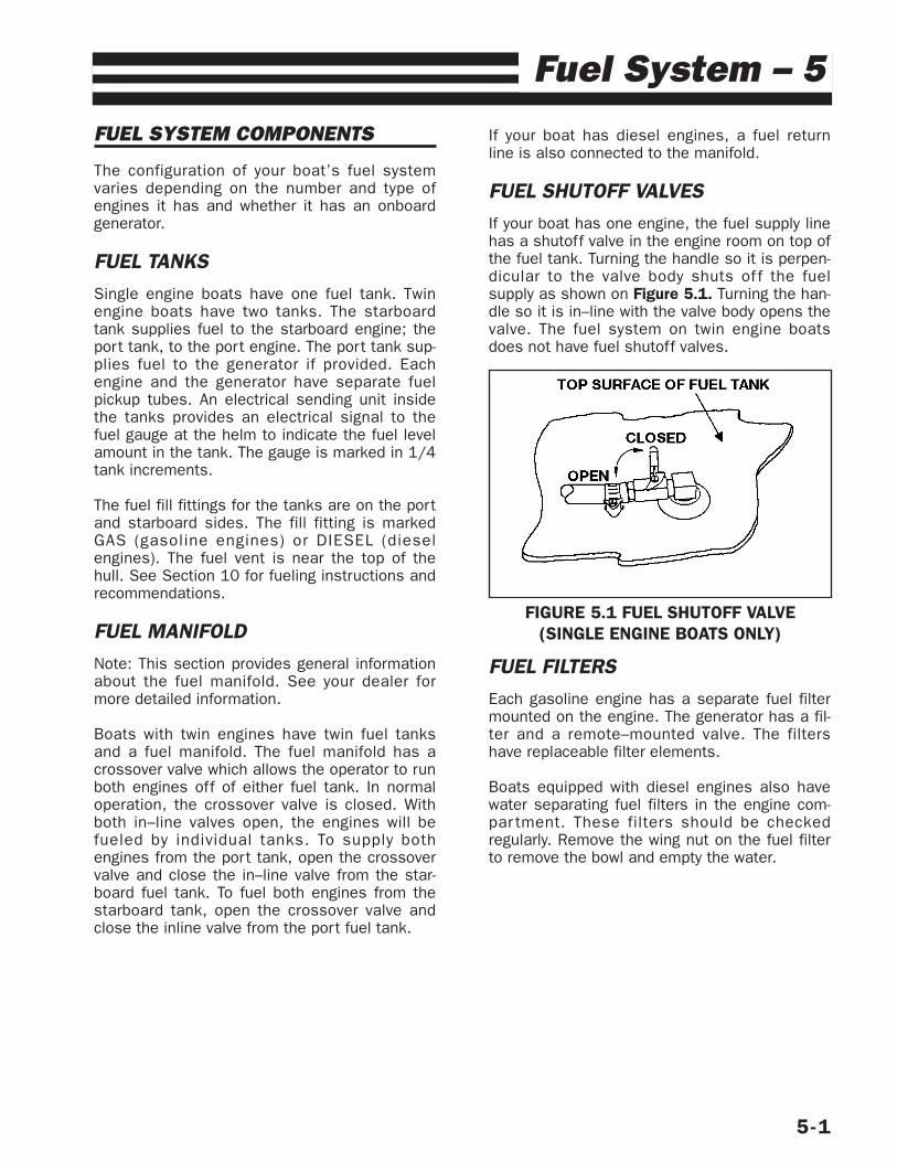
FUEL SYSTEM COMPONENTS
The configuration of your boat’s fuel systemvaries depending on the number and type ofengines it has and whether it has an onboardgenerator.
FUEL TANKSSingle engine boats have one fuel tank. Twinengine boats have two tanks. The starboardtank supplies fuel to the starboard engine; theport tank, to the port engine. The port tank sup-plies fuel to the generator if provided. Eachengine and the generator have separate fuelpickup tubes. An electrical sending unit insidethe tanks provides an electrical signal to thefuel gauge at the helm to indicate the fuel levelamount in the tank. The gauge is marked in 1/4tank increments.
The fuel fill fittings for the tanks are on the portand starboard sides. The fill fitting is markedGAS (gasoline engines) or DIESEL (dieselengines). The fuel vent is near the top of thehull. See Section 10 for fueling instructions andrecommendations.
FUEL MANIFOLDNote: This section provides general informationabout the fuel manifold. See your dealer formore detailed information.
Boats with twin engines have twin fuel tanksand a fuel manifold. The fuel manifold has acrossover valve which allows the operator to runboth engines off of either fuel tank. In normaloperation, the crossover valve is closed. Withboth in–line valves open, the engines will befueled by individual tanks. To supply bothengines from the port tank, open the crossovervalve and close the in–line valve from the star-board fuel tank. To fuel both engines from thestarboard tank, open the crossover valve andclose the inline valve from the port fuel tank.
If your boat has diesel engines, a fuel returnline is also connected to the manifold.
FUEL SHUTOFF VALVESIf your boat has one engine, the fuel supply linehas a shutoff valve in the engine room on top ofthe fuel tank. Turning the handle so it is perpen-dicular to the valve body shuts of f the fuelsupply as shown on Figure 5.1. Turning the han-dle so it is in–line with the valve body opens thevalve. The fuel system on twin engine boatsdoes not have fuel shutoff valves.
FUEL FILTERSEach gasoline engine has a separate fuel filtermounted on the engine. The generator has a fil-ter and a remote–mounted valve. The filtershave replaceable filter elements.
Boats equipped with diesel engines also havewater separating fuel filters in the engine com-par tment. These filters should be checkedregularly. Remove the wing nut on the fuel filterto remove the bowl and empty the water.
5-1
Fuel System – 5
FIGURE 5.1 FUEL SHUTOFF VALVE(SINGLE ENGINE BOATS ONLY)
5-2
FUEL SYSTEM TROUBLESHOOTING
PROBLEM
Fuel overflows at fill plate(tank not full)
Water or moisture in fueltank
Engine cranks but will notstart (fuel system)
CAUSE
Fill or vent line blocked
Cap on deck fuel fill platenot tight
Condensation forming onwalls of partially filled tank
Poor quality fuel frommarina tanks
Lack of fuel
Clogged fuel filter
No fuel reaching enginewith all fuel valves open.
Contaminated fuel
SOLUTION
Check lines. Clear obstruction from line orstraighten line if kinked.
Check cap; tighten.
Gasoline engines: Add fuel drying productto fuel supply. See your dealer for recom-mendations.
Diesel engines: Check fuel/water separa-tors; drain if necessary. Check with yourdealer.
Follow remedies for “Condensation”above. If remedies fail to correct problem,fuel tank and l ines may need to bedrained and flushed. See your dealer forservice.
Clean fuel filter, check fuel level; checkwhether anti–siphon valve, if so equipped,is stuck shut.
Improper starting procedure Review start-ing procedures in engine manual.
Check and replace fuel filter element.
Check fuel pump, fuel pump filter, carbu-retor fuel filter, and fuel tank line forcracked flanges or restricted fittings.
Inspect for water or other contaminants infuel. If contaminated, drain tank and flushwith fresh fuel.
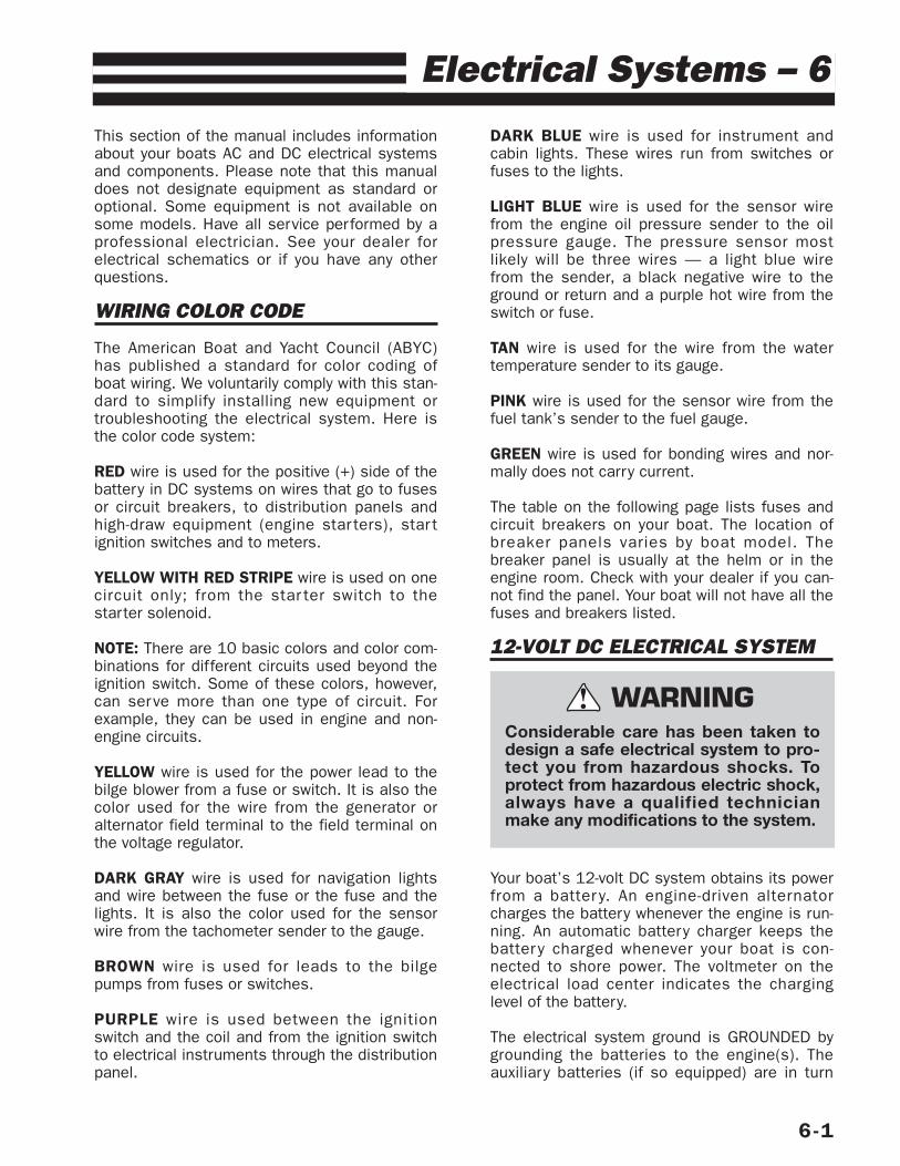
This section of the manual includes informationabout your boats AC and DC electrical systemsand components. Please note that this manualdoes not designate equipment as standard oroptional. Some equipment is not available onsome models. Have all service performed by aprofessional electrician. See your dealer forelectrical schematics or if you have any otherquestions.
WIRING COLOR CODE
The American Boat and Yacht Council (ABYC)has published a standard for color coding ofboat wiring. We voluntarily comply with this stan-dard to simplify installing new equipment ortroubleshooting the electrical system. Here isthe color code system:
RED wire is used for the positive (+) side of thebattery in DC systems on wires that go to fusesor circuit breakers, to distribution panels andhigh-draw equipment (engine star ters), star tignition switches and to meters.
YELLOW WITH RED STRIPE wire is used on onecircuit only; from the star ter switch to thestarter solenoid.
NOTE: There are 10 basic colors and color com-binations for different circuits used beyond theignition switch. Some of these colors, however,can serve more than one type of circuit. Forexample, they can be used in engine and non-engine circuits.
YELLOW wire is used for the power lead to thebilge blower from a fuse or switch. It is also thecolor used for the wire from the generator oralternator field terminal to the field terminal onthe voltage regulator.
DARK GRAY wire is used for navigation lightsand wire between the fuse or the fuse and thelights. It is also the color used for the sensorwire from the tachometer sender to the gauge.
BROWN wire is used for leads to the bilgepumps from fuses or switches.
PURPLE wire is used between the ignitionswitch and the coil and from the ignition switchto electrical instruments through the distributionpanel.
DARK BLUE wire is used for instrument andcabin lights. These wires run from switches orfuses to the lights.
LIGHT BLUE wire is used for the sensor wirefrom the engine oil pressure sender to the oilpressure gauge. The pressure sensor mostlikely will be three wires — a light blue wirefrom the sender, a black negative wire to theground or return and a purple hot wire from theswitch or fuse.
TAN wire is used for the wire from the watertemperature sender to its gauge.
PINK wire is used for the sensor wire from thefuel tank’s sender to the fuel gauge.
GREEN wire is used for bonding wires and nor-mally does not carry current.
The table on the following page lists fuses andcircuit breakers on your boat. The location ofbreaker panels varies by boat model. Thebreaker panel is usually at the helm or in theengine room. Check with your dealer if you can-not find the panel. Your boat will not have all thefuses and breakers listed.
12-VOLT DC ELECTRICAL SYSTEM
Your boat’s 12-volt DC system obtains its powerfrom a batter y. An engine-driven alternatorcharges the battery whenever the engine is run-ning. An automatic battery charger keeps thebatter y charged whenever your boat is con-nected to shore power. The voltmeter on theelectrical load center indicates the charginglevel of the battery.
The electrical system ground is GROUNDED bygrounding the batteries to the engine(s). Theauxiliary batteries (if so equipped) are in turn
6-1
Electrical Systems – 6
Considerable care has been taken todesign a safe electrical system to pro-tect you from hazardous shocks. Toprotect from hazardous electric shock,always have a qualified technicianmake any modifications to the system.
WARNING!
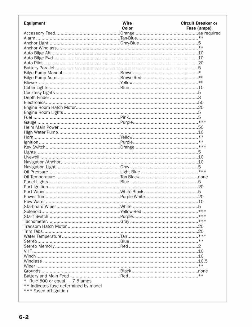
6-2
Equipment Wire Circuit Breaker orColor Fuse (amps)
Accessory Feed................................................Orange ..............................................as requiredAlarm ..............................................................Tan-Blue.............................................**Anchor Light.....................................................Gray-Blue ...........................................5Anchor Windlass........................................................................................................**Auto Bilge Aft ............................................................................................................10Auto Bilge Fwd ..........................................................................................................10Auto Pilot..................................................................................................................20Battery Parallel .........................................................................................................5Bilge Pump Manual ..........................................Brown................................................*Bilge Pump Auto...............................................Brown-Red .........................................**Blower ............................................................Yellow................................................**Cabin Lights ....................................................Blue ..................................................10Courtesy Lights .........................................................................................................5Depth Finder .............................................................................................................3Electronics................................................................................................................50Engine Room Hatch Motor..........................................................................................20Engine Room Lights...................................................................................................5Fuel ................................................................Pink...................................................5Gauge .............................................................Purple................................................***Helm Main Power ......................................................................................................50High Water Pump.......................................................................................................10Horn................................................................Yellow................................................**Ignition............................................................Purple................................................**Key Switch.......................................................Orange ..............................................***Lights .......................................................................................................................5Livewell ....................................................................................................................10Navigation/Anchor.....................................................................................................10Navigation Light ...............................................Gray ..................................................5Oil Pressure.....................................................Light Blue ..........................................***Oil Temperature ...............................................Tan-Black ...........................................nonePanel Lights.....................................................Blue ..................................................5Port Ignition ..............................................................................................................20Port Wiper .......................................................White-Black........................................5Power Trim.......................................................Purple-White.......................................20Raw Water ................................................................................................................10Starboard Wiper ...............................................White ................................................5Solenoid..........................................................Yellow-Red .........................................***Start Switch.....................................................Purple................................................***Tachometer......................................................Gray ..................................................***Transom Hatch Motor ................................................................................................20Trim Tabs..................................................................................................................20Water Temperature ...........................................Tan....................................................***Stereo.............................................................Blue ..................................................**Stereo Memory ................................................Red ...................................................2VHF ..........................................................................................................................10Winch .......................................................................................................................10Windlass ..................................................................................................................10.5Wiper .......................................................................................................................**Grounds ..........................................................Black.................................................noneBattery and Main Feed .....................................Red ...................................................*** Rule 500 or equal — 7.5 amps** Indicates fuse determined by model*** Fused off ignition
grounded to the cranking batteries. The enginesare connected by a ground cable for addedassurance of proper grounding. The engines arethen grounded to a bonding strip in the enginecompartment. This type of negative ground sys-tem is the approved system for marine DCelectrical systems. If additional equipment is tobe installed, it must be adaptable to the nega-tive ground system. When installing additionalequipment, ensure that each item’s currentsupply is taken from the main DC distributionpanel. This service should be performed only byyour dealer. All required additional circuit protec-tion must also be added at the DC distributionpanel.
The DC switch breakers allow you to interrupt orenable a circuit and they also protect the sys-tem by shutting down power if a short circuit oran overload occurs.
NOTE: Power feeds for accessory equipmentmust NOT be taken from the voltmeter terminals.
BATTERIES
Your dealer has installed batteries which supplypower to the DC electrical system components.Check with your dealer if you have questionsabout battery capacity. Marine batteries providehigh reserve capacity plus cold cranking perfor-mance. When the engine is running, the batteryis charged automatically. If your boat has twinengines, the starboard battery is the “house”battery, the one that powers any DC equipmenton your boat.
Batteries produce hydrogen and oxygen gaseswhen being charged. These explosive gasesescape through the vent/fill caps and may forman explosive atmosphere around the battery ifventilation is poor. This gas may remain aroundthe batter y for several hours after charging.
Sparks or flames can ignite the gas and causean explosion.
BATTERY PARALLELING SWITCHOn some boats with twin engines, you can usethe batter y paralleling switch to star t oneengine using both batteries. Use this switch tostart an engine if either battery does not havesufficient power to start the engine because ofa low charge level. The switch is at the helm.
BATTERY CHARGERThe boat’s batteries are normally charged when-ever the engines are running. If you are dockedfor an extended period of time, operating DCdevices and equipment will drain the powerfrom the batteries. Unless the batteries arekept charged, they may not have enough powerto start the engines when you need them.
If your boat is equipped with a battery charger,it will automatically charge the batteries whenyour boat is connected to shore power or whenthe generator is running and the BATTERYCHARGER breaker at the AC CONTROL panel isswitched to ON.
Leaving the battery charger switch on wheneverAC power is available is a good idea. It will keepthe batteries fully charged. After the batteriesare recharged, it provides a maintenance ortrickle charge as needed.
ALTERNATORSThe engine alternators will recharge the batter-ies while the engines are running. Voltageregulators control the rate of charge by sensingvoltage variations and increase or decrease out-put accordingly.
OVERLOAD PROTECTIONThe engine is equipped with a circuit breaker toprotect the engine wiring harness and instru-mentation power leads. If an electrical overloadoccurs, a circuit breaker will open and interruptcurrent flow when the circuit draw exceeds therated amperage. Refer to your engine owner’smanual for location and resetting procedure.
DUAL BATTERY SWITCHThe dual battery switch enables DC power to beused from one or two batteries. It controlspower to the engine and all 12-volt electricalequipment, except the automatic bilge pump
6-3
POISON! Batteries contain sulfuricacid which can cause severe burns.Avoid contact with skin, eyes or cloth-ing. Wear goggles, rubber gloves andprotective apron when working with abattery. In case of contact, flush withwater at least 15 minutes. If swal-lowed, drink large quantities of wateror milk. Follow with Milk of Magnesia,beaten egg or vegetable oil. Get medi-cal attention immediately.
WARNING!

and the stereo memory. The settings availableare OFF, 1, 2 and ALL. We recommend usingonly one battery at a time by using the numberone (1) or two (2) setting. Avoid using the ALLsetting unless a single battery is not sufficientto start the engine.
IMPORTANT: The dual battery switch should bein the OFF setting when the boat is not in useand especially while the boat is unattended.
While in the OFF setting, only the automaticbilge pump and stereo presets are suppliedwith DC power. All other electrical items areOFF.
The description and function for each of the set-tings on the dual battery switch is describedbelow:
• OFF: All 12-volt power to boat is shut OFFexcept for the automatic bilge pump andstereo presets. When boat is unattended forextended periods of time, turn the dual bat-tery switch to the OFF position.
• Setting one (1) will use battery #1 to powerengine and all 12-volt equipment. Battery#2 is isolated and remains in reserve. Bat-tery #1 is charged by the alternator.
• Setting two (2) uses battery #2. Except forbilge pump, batter y #1 is isolated andremains in reserve. Battery #2 is chargedby the alternator.
• Setting ALL will use both batteries. Both bat-teries are used by the engine and all 12-voltequipment and are charged by the alternatorwhen the engine is running.
NOTE: Rotating battery usage will increase bat-tery longevity.
Some twin engine models will have two dualbattery switches, one for each engine and bat-tery. The port side switch should be in positionnumber one (1) and the starboard side switch
should be in position number two (2) whenstarting the engines.
If you can’t start an engine because the batteryis low, try starting the other engine. Once thesecond engine is running, turn both batter yswitches to all, and then start the first engineusing both batteries. Once the first engine isrunning, return both battery switches to the pre-ferred setting.
AC ELECTRICAL SYSTEM
Your boat has been equipped with an AC electri-cal system which meets or exceeds nationalstandards at the time it was built. To work, yourboat’s AC system must be connected to a shorepower supply or the generator.
Dockside power service is available in 110 voltor 220 volt configurations. In North Americanand Pacific Rim countries, the standard powersupply is 110 V, 60 her tz (Hz). However, insome European countries, the standard powersupply is 220 V, 50 Hz.
The main AC breaker(s) on your boat turns yourentire AC system on and off, allowing you tocheck for proper voltage and polarity immedi-ately after a shore power connection has beenmade and before individual circuits are enabled.These switches have an LED indicator to indi-cate when they are on. Most panels also have atransfer switch which allows you to operatesome functions on the second load panel fromthe first load panel.
TRANSFER SWITCHThe transfer switch can be used to temporarilyrun equipment from AC Load Group 2 off of theshore power cord for AC Load Group 1. With ashore power cord attached to AC power hookup#1 flip the transfer switch to be able to runselected equipment from Load Group 2. Becareful not to exceed 30 amps on one powercord. The table on page 6–7 lists the amperagedrawn by AC components.
NOTE: Exceeding 30 amps on one power cordwill cause the main service breaker to trip. Ifthe main breaker trips, shut off equipment toreduce the load before resetting the main ser-vice breaker.
6-4
Do not turn dual battery switch to OFFsetting while engine is running. Thealternator and electrical wiring may bedamaged.
DANGER!
SHORE POWER
Your boat has a single male receptacle outsideon the deck for shore power connection (tworeceptacles if you have air conditioning).
Before you connect your boat to shore power,turn off the main cabin circuit breakers. Attachthe shore power cord to the boat first and turnclockwise to lock. Thread the locking ring on thecord to secure it to the receptacle. Connectingthe cord to the boat first will prevent dropping a“hot” cord into the water. (When you leave thedock, remove the cord from the dockside shoreoutlet first.) If you have any questions, contactyour dealer.
Make sure the dockside shore power breaker isOFF; then plug in the cord. Turn the docksideshore power breaker on. Immediately check thepolarity lights on the main electrical panel in theboat. If the REVERSED POLARITY light on thepanel illuminates, do not turn on the maincabin breaker. Turn of f the dockside shorepower breaker and disconnect your shore powercord. Inform the marina manager of the prob-lem. If you have any questions, contact yourdealer.
Important: Some equipment will not work ormay be damaged if polarity is reversed. Damagecaused by reversed polarity is not coveredunder your warranty. Be sure polarity is correctwhen you connect your boat to shore power.
Note: Reversed polarity occurs only with 110 Vsystems. It is not a concern for boats having220 V systems.
An AC circuit may overload if the current draw(amperage) of the accessories in use exceedsthe capacity of the load group. For each loadgroup, an AC amp indicator in the main electri-cal panel indicates the amperage draw. If acircuit overloads, turning off one or more acces-sories may be necessar y while you operateanother.
GENERATOR The optional onboard generator provides ACpower to your boat’s electrical system. If yourboat has a generator, it is mounted in theengine compartment.
Accidental starting of the generator can causesevere personal injury or death. Stop generatorand disable by disconnecting batter y cables(negative [–] cable first) when maintenance orrepairs are made to the engine, controls, orgenerator. Do not disconnect cables if gasfumes are present.
Note: Follow all generator instructions in theoperator’s manual. The manual includesdetailed information on specifications and pro-cedures for safe operation, maintenance, andwinterizing. It also explains how you can obtainservice for the generator, if required. The man-ual is in your owner’s packet.
Follow these procedures to operate the generator:
1. Run bilge blower for five minutes beforestarting generator. Run blower while genera-tor is operating.
2. Make sure seawater intake valve (seacock)for the generator is open. Seacock mustremain open at all times when generator isoperating. Seawater strainer must be free ofdebris to prevent clogging intake. Inspectseawater strainer frequently.
Note: Wellcraft recommends not using thegenerator when underway. When underwayand not using the generator, the seacockshould be closed.
3. Press or toggle START switch on main panelin cabin. When star ting generator, neveroperate starter for more than 30 seconds.Wait at least 30 seconds before eachattempted start.
On the generator in the engine compartmentare a choke and starter switch. If startingthe generator from the cabin is difficult, usethe choke and starter on the generator.
4. Look over side of boat and check for waterflowing from discharge port. If water is notflowing, stop the generator. Check for thefollowing: blocked water intake, air in line,clogged sea strainer, or closed sea cockthat should be open. Correct the problembefore restarting the generator.
6-5
To prevent damage to electrical sys-tem, never operate shore powersystem at less than 105 volts.
DANGER!
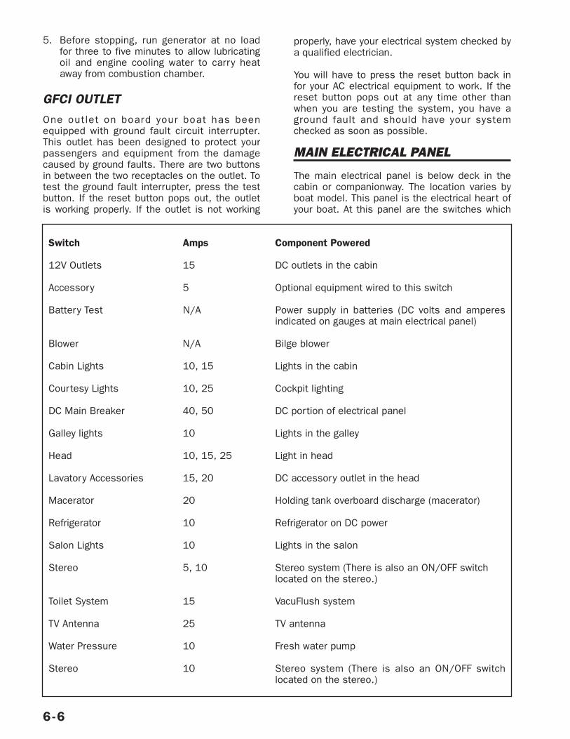
5. Before stopping, run generator at no loadfor three to five minutes to allow lubricatingoil and engine cooling water to carry heataway from combustion chamber.
GFCI OUTLET One outlet on board your boat has beenequipped with ground fault circuit interrupter.This outlet has been designed to protect yourpassengers and equipment from the damagecaused by ground faults. There are two buttonsin between the two receptacles on the outlet. Totest the ground fault interrupter, press the testbutton. If the reset button pops out, the outletis working properly. If the outlet is not working
properly, have your electrical system checked bya qualified electrician.
You will have to press the reset button back infor your AC electrical equipment to work. If thereset button pops out at any time other thanwhen you are testing the system, you have aground fault and should have your systemchecked as soon as possible.
MAIN ELECTRICAL PANEL
The main electrical panel is below deck in thecabin or companionway. The location varies byboat model. This panel is the electrical heart ofyour boat. At this panel are the switches which
6-6
Switch Amps Component Powered
12V Outlets 15 DC outlets in the cabin
Accessory 5 Optional equipment wired to this switch
Battery Test N/A Power supply in batteries (DC volts and amperesindicated on gauges at main electrical panel)
Blower N/A Bilge blower
Cabin Lights 10, 15 Lights in the cabin
Courtesy Lights 10, 25 Cockpit lighting
DC Main Breaker 40, 50 DC portion of electrical panel
Galley lights 10 Lights in the galley
Head 10, 15, 25 Light in head
Lavatory Accessories 15, 20 DC accessory outlet in the head
Macerator 20 Holding tank overboard discharge (macerator)
Refrigerator 10 Refrigerator on DC power
Salon Lights 10 Lights in the salon
Stereo 5, 10 Stereo system (There is also an ON/OFF switch located on the stereo.)
Toilet System 15 VacuFlush system
TV Antenna 25 TV antenna
Water Pressure 10 Fresh water pump
Stereo 10 Stereo system (There is also an ON/OFF switchlocated on the stereo.)
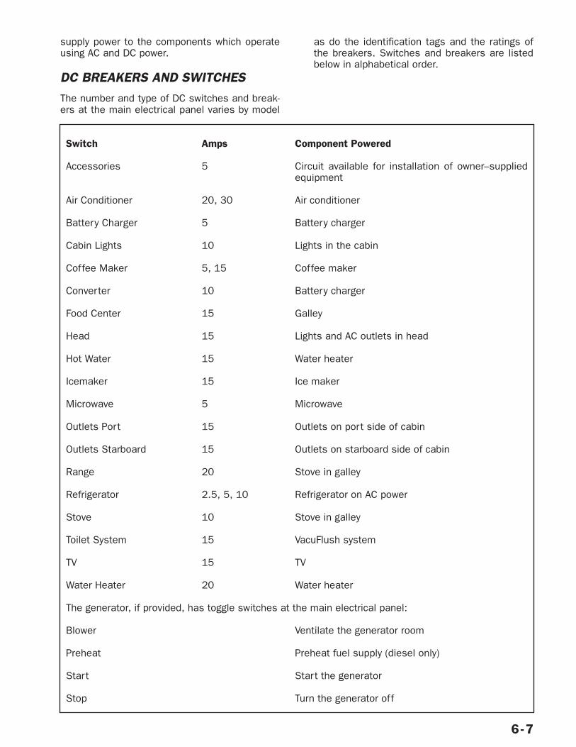
supply power to the components which operateusing AC and DC power.
DC BREAKERS AND SWITCHESThe number and type of DC switches and break-ers at the main electrical panel varies by model
as do the identification tags and the ratings ofthe breakers. Switches and breakers are listedbelow in alphabetical order.
6-7
Switch Amps Component Powered
Accessories 5 Circuit available for installation of owner–suppliedequipment
Air Conditioner 20, 30 Air conditioner
Battery Charger 5 Battery charger
Cabin Lights 10 Lights in the cabin
Coffee Maker 5, 15 Coffee maker
Converter 10 Battery charger
Food Center 15 Galley
Head 15 Lights and AC outlets in head
Hot Water 15 Water heater
Icemaker 15 Ice maker
Microwave 5 Microwave
Outlets Port 15 Outlets on port side of cabin
Outlets Starboard 15 Outlets on starboard side of cabin
Range 20 Stove in galley
Refrigerator 2.5, 5, 10 Refrigerator on AC power
Stove 10 Stove in galley
Toilet System 15 VacuFlush system
TV 15 TV
Water Heater 20 Water heater
The generator, if provided, has toggle switches at the main electrical panel:
Blower Ventilate the generator room
Preheat Preheat fuel supply (diesel only)
Start Start the generator
Stop Turn the generator off
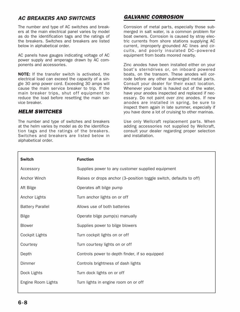
AC BREAKERS AND SWITCHESThe number and type of AC switches and break-ers at the main electrical panel varies by modelas do the identification tags and the ratings ofthe breakers. Switches and breakers are listedbelow in alphabetical order.
AC panels have gauges indicating voltage of ACpower supply and amperage drawn by AC com-ponents and accessories.
NOTE: If the transfer switch is activated, theelectrical load can exceed the capacity of a sin-gle 30 amp power cord. Exceeding 30 amps willcause the main service breaker to trip. If themain breaker trips, shut of f equipment toreduce the load before resetting the main ser-vice breaker.
HELM SWITCHES
The number and type of switches and breakersat the helm varies by model as do the identifica-tion tags and the ratings of the breakers.Switches and breakers are listed below inalphabetical order.
GALVANIC CORROSION
Corrosion of metal parts, especially those sub-merged in salt water, is a common problem forboat owners. Corrosion is caused by stray elec-tric currents from shore stations supplying ACcurrent, improperly grounded AC lines and cir-cuits, and poorly insulated DC–poweredequipment from boats moored nearby.
Zinc anodes have been installed either on yourboat’s sterndrives or, on inboard poweredboats, on the transom. These anodes will cor-rode before any other submerged metal parts.Consult your dealer for their exact location.Whenever your boat is hauled out of the water,have your anodes inspected and replaced if nec-essary. Do not paint over zinc anodes. If newanodes are installed in spring, be sure toinspect them again in late summer, especially ifyou have done a lot of cruising to other marinas.
Use only Wellcraft replacement par ts. Whenadding accessories not supplied by Wellcraft,consult your dealer regarding proper selectionand installation.
6-8
Switch Function
Accessory Supplies power to any customer supplied equipment
Anchor Winch Raises or drops anchor (3–position toggle switch, defaults to off)
Aft Bilge Operates aft bilge pump
Anchor Lights Turn anchor lights on or off
Battery Parallel Allows use of both batteries
Bilge Operate bilge pump(s) manually
Blower Supplies power to bilge blowers
Cockpit Lights Turn cockpit lights on or off
Courtesy Turn courtesy lights on or off
Depth Controls power to depth finder, if so equipped
Dimmer Controls brightness of dash lights
Dock Lights Turn dock lights on or off
Engine Room Lights Turn lights in engine room on or off
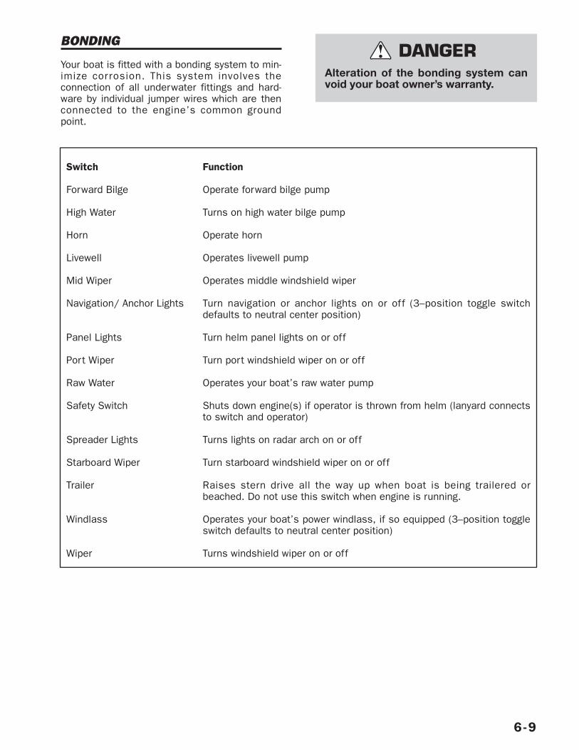
BONDING
Your boat is fitted with a bonding system to min-imize corrosion. This system involves theconnection of all underwater fittings and hard-ware by individual jumper wires which are thenconnected to the engine’s common groundpoint.
6-9
Alteration of the bonding system canvoid your boat owner’s warranty.
DANGER!
Switch Function
Forward Bilge Operate forward bilge pump
High Water Turns on high water bilge pump
Horn Operate horn
Livewell Operates livewell pump
Mid Wiper Operates middle windshield wiper
Navigation/ Anchor Lights Turn navigation or anchor lights on or off (3–position toggle switchdefaults to neutral center position)
Panel Lights Turn helm panel lights on or off
Port Wiper Turn port windshield wiper on or off
Raw Water Operates your boat’s raw water pump
Safety Switch Shuts down engine(s) if operator is thrown from helm (lanyard connectsto switch and operator)
Spreader Lights Turns lights on radar arch on or off
Starboard Wiper Turn starboard windshield wiper on or off
Trailer Raises stern drive all the way up when boat is being trailered orbeached. Do not use this switch when engine is running.
Windlass Operates your boat’s power windlass, if so equipped (3–position toggleswitch defaults to neutral center position)
Wiper Turns windshield wiper on or off
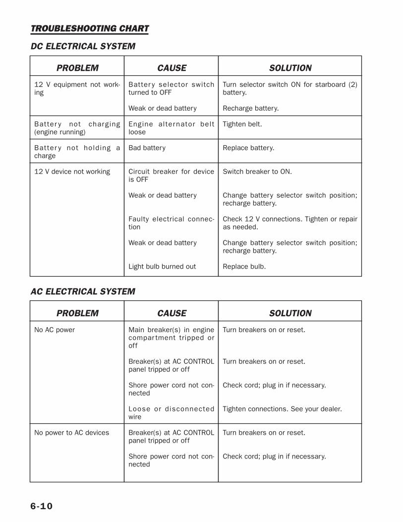
6-10
PROBLEM
12 V equipment not work-ing
Batter y not charging(engine running)
Batter y not holding acharge
12 V device not working
CAUSE
Batter y selector switchturned to OFF
Weak or dead battery
Engine alternator beltloose
Bad battery
Circuit breaker for deviceis OFF
Weak or dead battery
Faulty electrical connec-tion
Weak or dead battery
Light bulb burned out
SOLUTION
Turn selector switch ON for starboard (2)battery.
Recharge battery.
Tighten belt.
Replace battery.
Switch breaker to ON.
Change battery selector switch position;recharge battery.
Check 12 V connections. Tighten or repairas needed.
Change battery selector switch position;recharge battery.
Replace bulb.
TROUBLESHOOTING CHART
DC ELECTRICAL SYSTEM
AC ELECTRICAL SYSTEM
PROBLEM
No AC power
No power to AC devices
CAUSE
Main breaker(s) in enginecompar tment tripped oroff
Breaker(s) at AC CONTROLpanel tripped or off
Shore power cord not con-nected
Loose or disconnectedwire
Breaker(s) at AC CONTROLpanel tripped or off
Shore power cord not con-nected
SOLUTION
Turn breakers on or reset.
Turn breakers on or reset.
Check cord; plug in if necessary.
Tighten connections. See your dealer.
Turn breakers on or reset.
Check cord; plug in if necessary.

6-11
AC ELECTRICAL SYSTEM TROUBLESHOOTING
No power to AC devices(Continued)
Inadequate power to ACdevices (generator run-ning)
No power at AC outlets
Loose or disconnectedwire
Electrical demand greaterthan generator output
Outlet breakers in AC CON-TROL panel OFF
Ground fault interruptertripped
Tighten connections. See your dealer.
Switch of f devices and equipment notneeded.
Switch breakers to ON.
Reset button on outlet and test.
This section covers the appliances found in thegalley, the air conditioning system, the stereosystem and the TV. Power is supplied to manyof these components through a breaker switchin the main electrical panel.
STOVE
ALCOHOL/ELECTRIC
Your boat may be equipped with analcohol/electric stove. See the manufacturer’smanual for more information on use and main-tenance.
ELECTRIC Your boat may be equipped with an electricstove. This stove can only be operated whenyour boat is connected to shore power or whenthe generator is running. Refer to the stoveowner’s manual for details about using thisappliance safely.
REFRIGERATOR
The refrigerator supplied with your boat oper-ates off DC power from the battery or AC powerthrough the main electrical panel. Switch the DCbreaker for the refrigerator to ON to power therefrigerator from the battery. Using DC power tocool the interior of a warm refrigerator will takelonger than cooling it with AC power.
Important: The refrigerator can drain the powerfrom a battery in a short time, particularly ifother devices are powered from the DC powersupply. Operate the engines from time to timeto recharge the batteries if an AC power supplyis not available. See the refrigerator manual formore information.
OVEN
Your boat may have a microwave oven or a con-vection/microwave oven. The operation of eitherunit is similar.
The microwave oven is controlled by an elec-tronic touch control panel on the oven. Thecontrols for the convection oven are on theoven. The MICROWAVE or FOOD CENTERbreaker at the main panel must be on to usethe oven. For a detailed description of oven fea-tures, see the owner’s manual supplied by themanufacturer.
COFFEE MAKER
Your boat may be equipped with a coffee maker.See the equipment manufacturer’s manual forinformation operation and maintenance.
MARINE STEREO
This unit is a highly sensitive electronic tuningAM/FM stereo receiver with an optional CDplayer. It employs several electronic circuitsespecially designed for superb radio receptionon both AM and FM bands. Your boat has water-proof marine stereo speakers. The number ofspeakers and their location may vary on eachmodel. See the stereo owner’s manual for acomplete list of features and instructions.
7-1
Boat Equipment – 7
Alcohol flame can not be seen in directsunlight. Fueling an ignited burner cancause it to flare up. Do not light burnerunless flame is extinguished andburner is cool.
WARNING!
Use only manufacturer approved fuel.Always provide adequate ventilationwhen using an open flame. Do not usestove near fuel fill or fuel vent.
WARNING!
To reduce the risk of burns, electricshock, fire, injury to persons or expo-sure to excessive microwave energy,read ALL instructions before using themicrowave oven. Be sure to secureturntable while underway to preventdamage to the unit.
CAUTION!
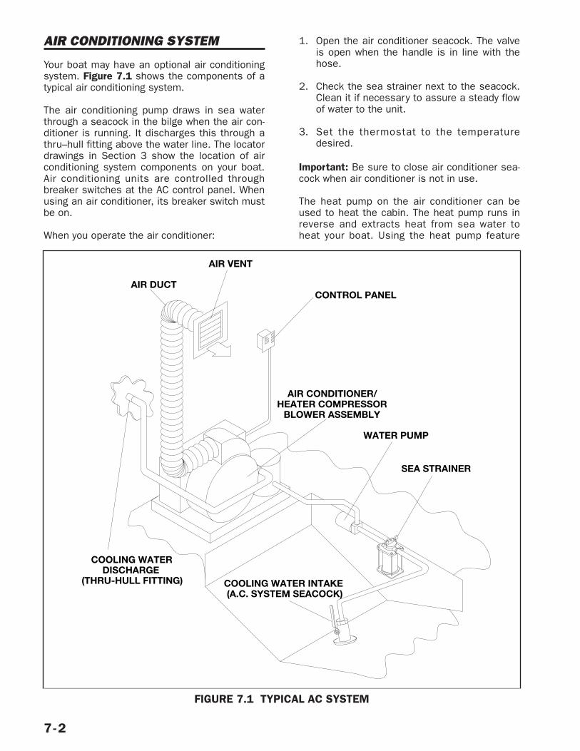
AIR CONDITIONING SYSTEM
Your boat may have an optional air conditioningsystem. Figure 7.1 shows the components of atypical air conditioning system.
The air conditioning pump draws in sea waterthrough a seacock in the bilge when the air con-ditioner is running. It discharges this through athru–hull fitting above the water line. The locatordrawings in Section 3 show the location of airconditioning system components on your boat.Air conditioning units are controlled throughbreaker switches at the AC control panel. Whenusing an air conditioner, its breaker switch mustbe on.
When you operate the air conditioner:
1. Open the air conditioner seacock. The valveis open when the handle is in line with thehose.
2. Check the sea strainer next to the seacock.Clean it if necessary to assure a steady flowof water to the unit.
3. Set the thermostat to the temperaturedesired.
Important: Be sure to close air conditioner sea-cock when air conditioner is not in use.
The heat pump on the air conditioner can beused to heat the cabin. The heat pump runs inreverse and extracts heat from sea water toheat your boat. Using the heat pump feature
7-2
WATER PUMP
SEA STRAINER
AIR DUCT
COOLING WATER INTAKE (A.C. SYSTEM SEACOCK)
AIR CONDITIONER/HEATER COMPRESSOR
BLOWER ASSEMBLY
CONTROL PANEL
AIR VENT
COOLING WATER DISCHARGE
(THRU-HULL FITTING)
FIGURE 7.1 TYPICAL AC SYSTEM
when the sea water temperature is below 40°can damage the air conditioning system.
Refer to the manual furnished with the air condi-tioning unit for more detailed informationregarding its operation.
AUTOMATIC FIRESUPPRESSION SYSTEM
Your boat may be equipped with an automaticfire suppression system in the engine compart-ment. This system uses a fire extinguishingagent. A heat–sensitive automatic nozzlereleases the agent as a vapor, cutting off thesupply of oxygen to the fire. The system’s indi-cator light is illuminated when the system isfully charged. When the system is discharged,the indicator light will go out. The light is on thedash or a separate monitoring panel, dependingon boat model.
If the system discharges, do not open enginecompartment for at least 15 minutes. Hot met-als or fuel can also begin cooling during thistime. Cautiously inspect compartment for causeof fire and damage to equipment. Have portableextinguishers readily available. Do not breathefire caused fumes or vapors.
Note: The fire suppression agent is an ozone–depleting substance. In order to help safeguardthe environment, following the manufacturer’smaintenance recommendations is important. Besure to check the equipment manual fordetailed information about safety precautionsand procedures for operating and maintainingthe fire suppression system.
TV/VCR (OPTIONAL)
Your boat may be equipped with a television setor TV/VCR combination. See the manufacturer’smanual for information on operation and main-tenance.
VHF RADIO
Your boat may be equipped with a VHF radio.See the manufacturer’s manual for informationon operation and maintenance.
7-3
If system discharges, immediately turnOFF engine, bilge blower(s), and elec-trical systems. Extinguish all smokingmaterials. Do not open engine com-partment. Fresh air supplies oxygen tofire and fire may flash back throughopening.
WARNING!
This section discusses your boat’s propulsionequipment. Depending on boat model, your boatis powered either by inboard engines through atransmission or by sterndrive(s). If your boathas a sterndrive, the manufacturer’s manual pro-vides detailed information about its operation.
Note: The information in this section, except fortroubleshooting, trim tabs, and propellersapplies primarily to inboard–powered boats.
PROPELLERS
The propellers supplied with your boat havebeen selected as the best propeller for averageuse. Consider keeping an extra set of propellerson your boat. If the propellers become dam-aged, you can replace them with the spares andcontinue your outing. Check with your dealer ifyou want to purchase an extra set.
Note: You, as owner, can change propeller sizesto suit other conditions. However, you assumeall responsibility for any damage caused by thechange in propeller size.
PROPELLER SHAFT
The propeller shaft is made of stainless steelwhich has excellent corrosion resistance andvery high strength. The coupling at one end ofthe shaft is bolted to the transmission. Theother end of the shaft is tapered, threaded, andkeyed for installation of the propeller.
STRUTS
Each propeller shaft is supported by struts fas-tened to the bottom of the hull. The struts havereplaceable bearings to minimize wear and toprotect the shaft at the points where it passesthrough the strut hubs. Strut bearings shouldbe lubricated by your dealer.
SHAFT LOG AND STUFFING BOX
The shaft log is a bronze tube inserted in anopening in the bottom of the boat for the pro-peller shaft. A shor t length of flexible hoseconnects the shaft stuffing box to the shaft log.
The stuf fing box keeps water from leakingaround the shaft into the boat. The stuffing boxhas a packing gland filled with waxed flax or
synthetic fiber rings compressed around theshaft by the packing retainer.
A very slight leak helps lubricate the packing.One drop every 60 seconds is desirable. Morethan one drop per minute indicates wearcaused by the rotating shaft. Tightening thepacking retainer slightly will usually stop exces-sive leakage. If the leakage continues aftertightening the retainer, the packing may needreplacement, the log may be out of alignment,or the shaft may be bent or scored. Have yourdealer check any persistent excess leakage.
Important: Overtightening the packing retainermay score the propeller shaft.
ALIGNMENTAligning the engine with the propeller shaft iscritical for smooth operation of your boat. Theshafts are properly aligned at the factory. Checkthe alignment after deliver y or an extendedlay–up. A slight misalignment can result in aloss of power, vibration, or wear in the bearings.
To check the alignment:
1. Remove the coupling bolts and spread thecouplings very slightly.
2. Use a feeler gauge to measure the spacebetween the couplings at the edges of thecoupling. The difference in reading shouldnot exceed 0.003 inch.
3. A second check is to leave the flange on theengine fixed and rotate the propeller shaftcoupling in 90° steps. Check the clearancebetween the fixed engine flange and therotating propeller flange with the feelergauge at the top. If the four measurementsdiffer by more than 0.003 inch, it may be anindication that there is a slight bend in thepropeller shaft. This is an important checkafter striking a submerged object.
4. The straightness of the shaft can be furtherchecked with the boat out of the water bysetting up a dial indicator on a solid fixedsurface and rotating the propeller shaft byhand (use the blades of the propeller toturn the shaft by hand. This test will clearlyindicate whether the propeller shaft hasbeen bent.
8-1
Underwater Gear – 8
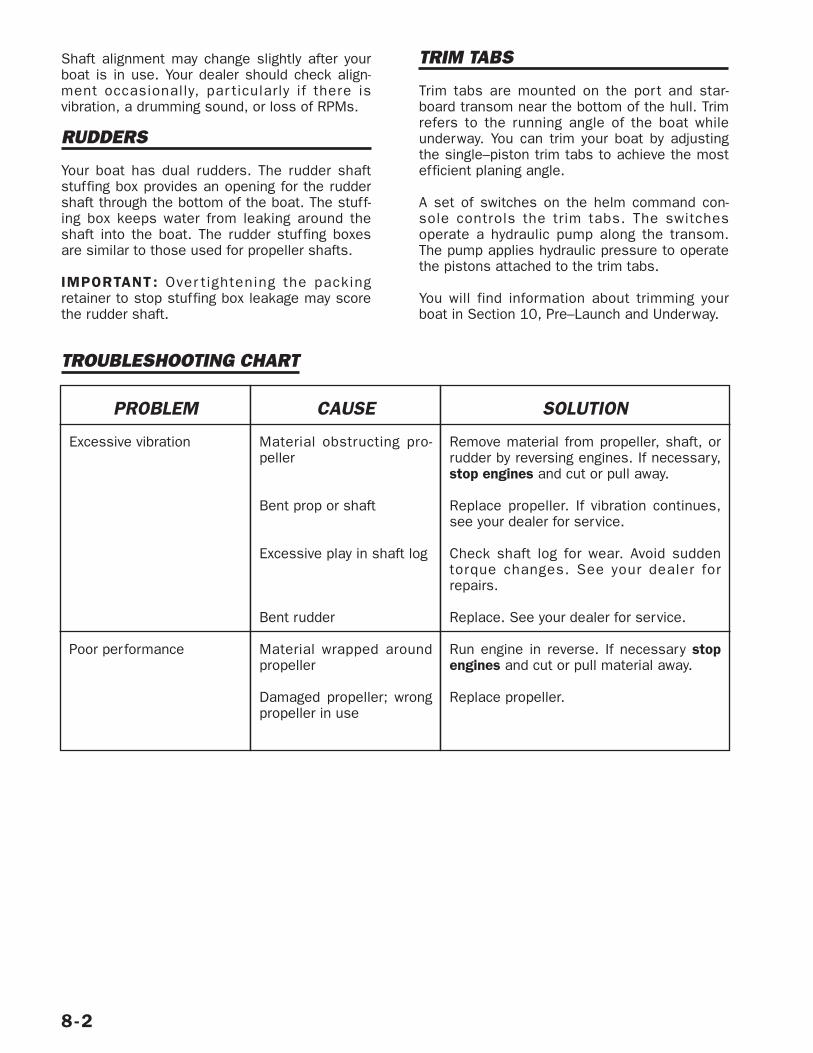
Shaft alignment may change slightly after yourboat is in use. Your dealer should check align-ment occasionally, par ticularly if there isvibration, a drumming sound, or loss of RPMs.
RUDDERS
Your boat has dual rudders. The rudder shaftstuffing box provides an opening for the ruddershaft through the bottom of the boat. The stuff-ing box keeps water from leaking around theshaft into the boat. The rudder stuffing boxesare similar to those used for propeller shafts.
IMPORTANT : Over tightening the packingretainer to stop stuffing box leakage may scorethe rudder shaft.
TRIM TABS
Trim tabs are mounted on the por t and star-board transom near the bottom of the hull. Trimrefers to the running angle of the boat whileunderway. You can trim your boat by adjustingthe single–piston trim tabs to achieve the mostefficient planing angle.
A set of switches on the helm command con-sole controls the trim tabs. The switchesoperate a hydraulic pump along the transom.The pump applies hydraulic pressure to operatethe pistons attached to the trim tabs.
You will find information about trimming yourboat in Section 10, Pre–Launch and Underway.
8-2
PROBLEM
Excessive vibration
Poor performance
CAUSE
Material obstructing pro-peller
Bent prop or shaft
Excessive play in shaft log
Bent rudder
Material wrapped aroundpropeller
Damaged propeller; wrongpropeller in use
SOLUTION
Remove material from propeller, shaft, orrudder by reversing engines. If necessary,stop engines and cut or pull away.
Replace propeller. If vibration continues,see your dealer for service.
Check shaft log for wear. Avoid suddentorque changes. See your dealer forrepairs.
Replace. See your dealer for service.
Run engine in reverse. If necessary stopengines and cut or pull material away.
Replace propeller.
TROUBLESHOOTING CHART
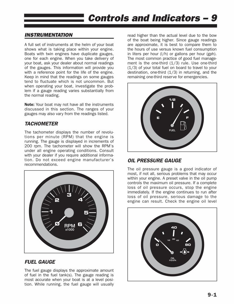
INSTRUMENTATION
A full set of instruments at the helm of your boatshows what is taking place within your engine.Boats with twin engines have duplicate gauges,one for each engine. When you take delivery ofyour boat, ask your dealer about normal readingsof the gauges. This information will provide youwith a reference point for the life of the engine.Keep in mind that the readings on some gaugestend to fluctuate which is not uncommon. Butwhen operating your boat, investigate the prob-lem if a gauge reading varies substantially fromthe normal reading.
Note: Your boat may not have all the instrumentsdiscussed in this section. The ranges of yourgauges may also vary from the readings listed.
TACHOMETER The tachometer displays the number of revolu-tions per minute (RPM) that the engine isrunning. The gauge is displayed in increments of200 rpm. The tachometer will show the RPM’sunder all engine operating conditions. Consultwith your dealer if you require additional informa-tion. Do not exceed engine manufacturer’srecommendations.
FUEL GAUGE The fuel gauge displays the approximate amountof fuel in the fuel tank(s). The gauge reading ismost accurate when your boat is at a level posi-tion. While running, the fuel gauge will usually
read higher than the actual level due to the bowof the boat being higher. Since gauge readingsare approximate, it is best to compare them tothe hours of use versus known fuel consumptionin liters per hour (l/h) or gallons per hour (gph).The most common practice of good fuel manage-ment is the one-third (1/3) rule. Use one-third(1/3) of your total fuel on board to travel to yourdestination, one-third (1/3) in returning, and theremaining one-third reserve for emergencies.
OIL PRESSURE GAUGE The oil pressure gauge is a good indicator ofmost, if not all, serious problems that may occurwithin your engine. A preset valve in the oil pumpcontrols the maximum oil pressure. If a completeloss of oil pressure occurs, stop the engineimmediately. If the engine continues to run afterloss of oil pressure, serious damage to theengine can result. Check the engine oil level
9-1
Controls and Indicators – 9
RPMx1000
0
1
23
4
5
6
FUEL
E
1/2
F
OILPSI/kPA
800
40
140280
420
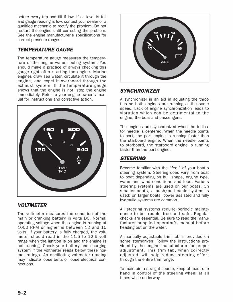
before every trip and fill if low. If oil level is fulland gauge reading is low, contact your dealer or aqualified mechanic to rectify the problem. Do notrestart the engine until correcting the problem.See the engine manufacturer’s specifications forcorrect pressure ranges.
TEMPERATURE GAUGE The temperature gauge measures the tempera-ture of the engine water cooling system. Youshould make a practice of always checking thisgauge right after star ting the engine. Marineengines draw sea water, circulate it through theengine, and expel it overboard through theexhaust system. If the temperature gaugeshows that the engine is hot, stop the engineimmediately. Refer to your engine owner’s man-ual for instructions and corrective action.
VOLTMETERThe voltmeter measures the condition of themain or cranking battery in volts DC. Normaloperating voltage when the engine is running at1000 RPM or higher is between 12 and 15volts. If your battery is fully charged, the volt-meter should read in the 11.5 to 12.5 voltrange when the ignition is on and the engine isnot running. Check your battery and chargingsystem if the voltmeter reads below these nor-mal ratings. An oscillating voltmeter readingmay indicate loose belts or loose electrical con-nections.
SYNCHRONIZERA synchronizer is an aid in adjusting the throt-tles so both engines are running at the samespeed. Lack of engine synchronization leads tovibration which can be detrimental to theengine, the boat and passengers.
The engines are synchronized when the indica-tor needle is centered. When the needle pointsto port, the port engine is running faster thanthe starboard engine. When the needle pointsto starboard, the starboard engine is runningfaster than the port engine.
STEERING
Become familiar with the “feel” of your boat’ssteering system. Steering does vary from boatto boat depending on hull shape, engine type,water and wind conditions and load. Varioussteering systems are used on our boats. Onsmaller boats, a push/pull cable system isused; on larger boats, power assisted and fullyhydraulic systems are common.
All steering systems require periodic mainte-nance to be trouble–free and safe. Regularchecks are essential. Be sure to read the manu-facturer supplied operator’s manual beforeheading out on the water.
A manually adjustable trim tab is provided onsome sterndrives. Follow the instructions pro-vided by the engine manufacturer for properadjustment. This trim tab, when correctlyadjusted, will help reduce steering ef for tthrough the entire trim range.
To maintain a straight course, keep at least onehand in control of the steering wheel at alltimes while underway.
9-2
TEMP°F/°C
240120
160 200
7085
100
VOLTS
12 14
1610
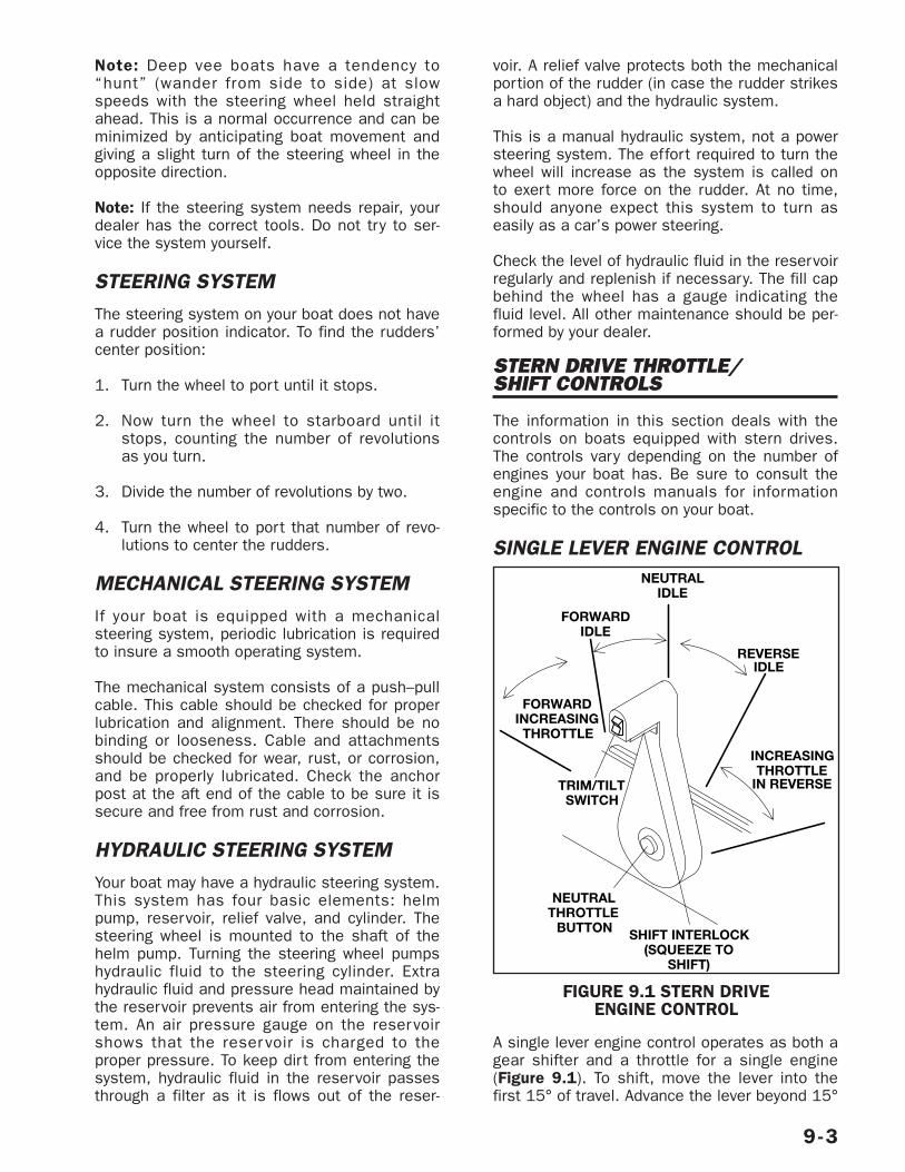
Note: Deep vee boats have a tendency to“hunt” (wander from side to side) at slowspeeds with the steering wheel held straightahead. This is a normal occurrence and can beminimized by anticipating boat movement andgiving a slight turn of the steering wheel in theopposite direction.
Note: If the steering system needs repair, yourdealer has the correct tools. Do not try to ser-vice the system yourself.
STEERING SYSTEMThe steering system on your boat does not havea rudder position indicator. To find the rudders’center position:
1. Turn the wheel to port until it stops.
2. Now turn the wheel to starboard until itstops, counting the number of revolutionsas you turn.
3. Divide the number of revolutions by two.
4. Turn the wheel to port that number of revo-lutions to center the rudders.
MECHANICAL STEERING SYSTEM If your boat is equipped with a mechanicalsteering system, periodic lubrication is requiredto insure a smooth operating system.
The mechanical system consists of a push–pullcable. This cable should be checked for properlubrication and alignment. There should be nobinding or looseness. Cable and attachmentsshould be checked for wear, rust, or corrosion,and be properly lubricated. Check the anchorpost at the aft end of the cable to be sure it issecure and free from rust and corrosion.
HYDRAULIC STEERING SYSTEMYour boat may have a hydraulic steering system.This system has four basic elements: helmpump, reservoir, relief valve, and cylinder. Thesteering wheel is mounted to the shaft of thehelm pump. Turning the steering wheel pumpshydraulic fluid to the steering cylinder. Extrahydraulic fluid and pressure head maintained bythe reservoir prevents air from entering the sys-tem. An air pressure gauge on the reservoirshows that the reser voir is charged to theproper pressure. To keep dirt from entering thesystem, hydraulic fluid in the reservoir passesthrough a filter as it is flows out of the reser-
voir. A relief valve protects both the mechanicalportion of the rudder (in case the rudder strikesa hard object) and the hydraulic system.
This is a manual hydraulic system, not a powersteering system. The effort required to turn thewheel will increase as the system is called onto exert more force on the rudder. At no time,should anyone expect this system to turn aseasily as a car’s power steering.
Check the level of hydraulic fluid in the reservoirregularly and replenish if necessary. The fill capbehind the wheel has a gauge indicating thefluid level. All other maintenance should be per-formed by your dealer.
STERN DRIVE THROTTLE/SHIFT CONTROLS
The information in this section deals with thecontrols on boats equipped with stern drives.The controls vary depending on the number ofengines your boat has. Be sure to consult theengine and controls manuals for informationspecific to the controls on your boat.
SINGLE LEVER ENGINE CONTROL
A single lever engine control operates as both agear shifter and a throttle for a single engine(Figure 9.1). To shift, move the lever into thefirst 15° of travel. Advance the lever beyond 15°
9-3
FIGURE 9.1 STERN DRIVE ENGINE CONTROL
FORWARDINCREASINGTHROTTLE
NEUTRALIDLE
FORWARDIDLE
REVERSEIDLE
INCREASING THROTTLE
IN REVERSE
SHIFT INTERLOCK(SQUEEZE TO
SHIFT)
TRIM/TILTSWITCH
NEUTRAL THROTTLE
BUTTON
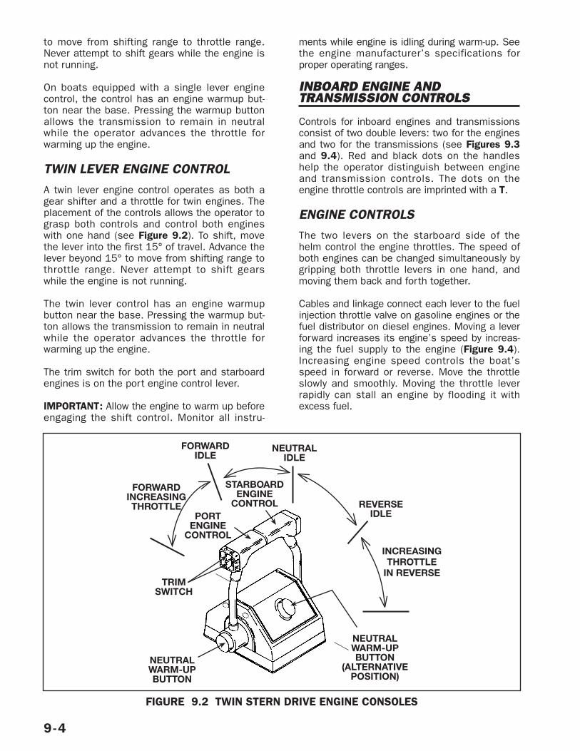
to move from shifting range to throttle range.Never attempt to shift gears while the engine isnot running.
On boats equipped with a single lever enginecontrol, the control has an engine warmup but-ton near the base. Pressing the warmup buttonallows the transmission to remain in neutralwhile the operator advances the throttle forwarming up the engine.
TWIN LEVER ENGINE CONTROLA twin lever engine control operates as both agear shifter and a throttle for twin engines. Theplacement of the controls allows the operator tograsp both controls and control both engineswith one hand (see Figure 9.2). To shift, movethe lever into the first 15° of travel. Advance thelever beyond 15° to move from shifting range tothrottle range. Never attempt to shift gearswhile the engine is not running.
The twin lever control has an engine warmupbutton near the base. Pressing the warmup but-ton allows the transmission to remain in neutralwhile the operator advances the throttle forwarming up the engine.
The trim switch for both the port and starboardengines is on the port engine control lever.
IMPORTANT: Allow the engine to warm up beforeengaging the shift control. Monitor all instru-
ments while engine is idling during warm-up. Seethe engine manufacturer’s specifications forproper operating ranges.
INBOARD ENGINE ANDTRANSMISSION CONTROLS
Controls for inboard engines and transmissionsconsist of two double levers: two for the enginesand two for the transmissions (see Figures 9.3and 9.4). Red and black dots on the handleshelp the operator distinguish between engineand transmission controls. The dots on theengine throttle controls are imprinted with a T.
ENGINE CONTROLSThe two levers on the starboard side of thehelm control the engine throttles. The speed ofboth engines can be changed simultaneously bygripping both throttle levers in one hand, andmoving them back and forth together.
Cables and linkage connect each lever to the fuelinjection throttle valve on gasoline engines or thefuel distributor on diesel engines. Moving a leverforward increases its engine’s speed by increas-ing the fuel supply to the engine (Figure 9.4).Increasing engine speed controls the boat’sspeed in forward or reverse. Move the throttleslowly and smoothly. Moving the throttle leverrapidly can stall an engine by flooding it withexcess fuel.
9-4
NEUTRALIDLE
REVERSEIDLE
FORWARDIDLE
FORWARDINCREASINGTHROTTLE
INCREASINGTHROTTLE
IN REVERSETRIM
SWITCH
NEUTRALWARM-UPBUTTON
NEUTRALWARM-UPBUTTON
(ALTERNATIVEPOSITION)
PORTENGINE
CONTROL
STARBOARDENGINE
CONTROL
FIGURE 9.2 TWIN STERN DRIVE ENGINE CONSOLES
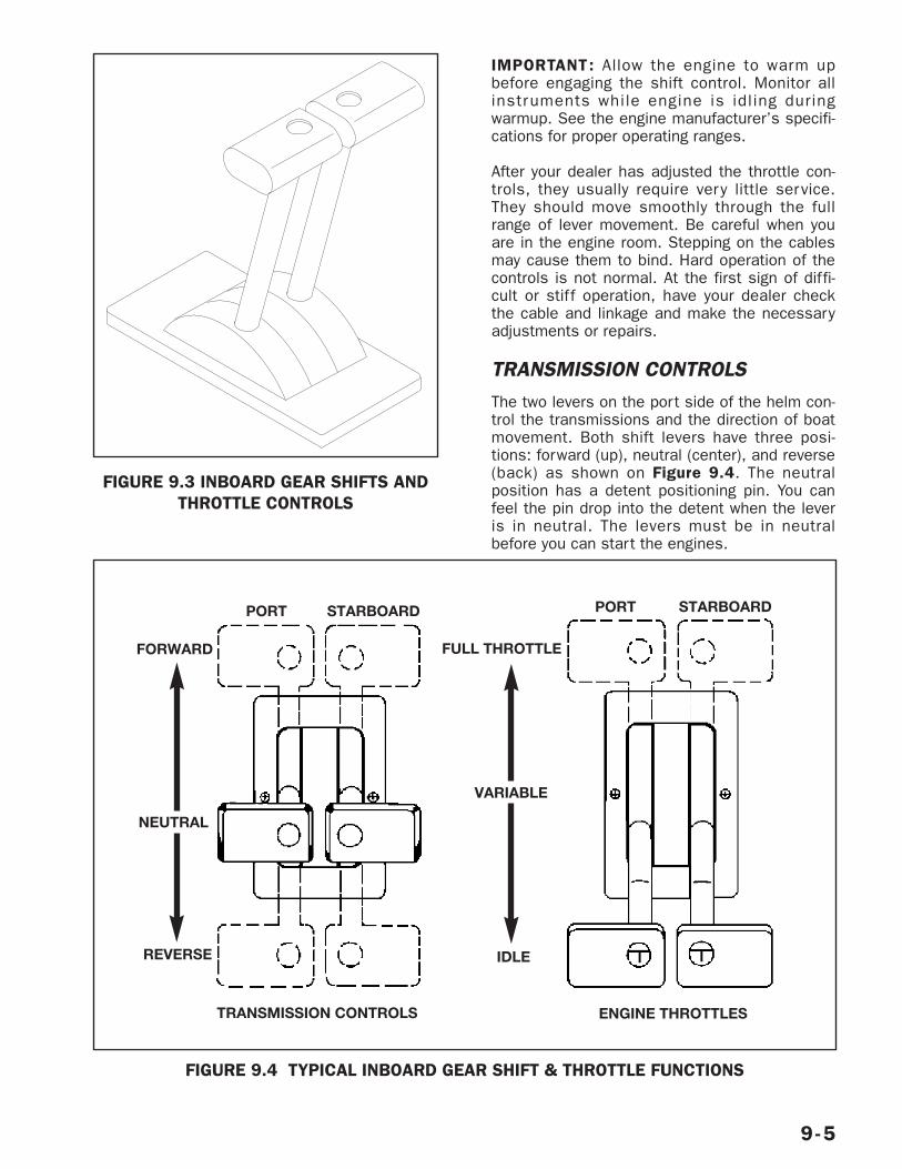
IMPORTANT: Allow the engine to warm upbefore engaging the shift control. Monitor allinstruments while engine is idling duringwarmup. See the engine manufacturer’s specifi-cations for proper operating ranges.
After your dealer has adjusted the throttle con-trols, they usually require very little service.They should move smoothly through the fullrange of lever movement. Be careful when youare in the engine room. Stepping on the cablesmay cause them to bind. Hard operation of thecontrols is not normal. At the first sign of diffi-cult or stiff operation, have your dealer checkthe cable and linkage and make the necessaryadjustments or repairs.
TRANSMISSION CONTROLSThe two levers on the port side of the helm con-trol the transmissions and the direction of boatmovement. Both shift levers have three posi-tions: forward (up), neutral (center), and reverse(back) as shown on Figure 9.4. The neutralposition has a detent positioning pin. You canfeel the pin drop into the detent when the leveris in neutral. The levers must be in neutralbefore you can start the engines.
9-5
FIGURE 9.3 INBOARD GEAR SHIFTS ANDTHROTTLE CONTROLS
FIGURE 9.4 TYPICAL INBOARD GEAR SHIFT & THROTTLE FUNCTIONS
STARBOARDPORT
IDLEREVERSE
TRANSMISSION CONTROLS ENGINE THROTTLES
NEUTRAL
FORWARD
VARIABLE
FULL THROTTLE
STARBOARDPORT
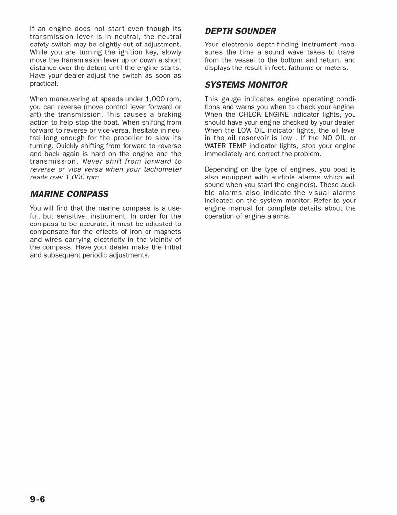
If an engine does not star t even though itstransmission lever is in neutral, the neutralsafety switch may be slightly out of adjustment.While you are turning the ignition key, slowlymove the transmission lever up or down a shortdistance over the detent until the engine starts.Have your dealer adjust the switch as soon aspractical.
When maneuvering at speeds under 1,000 rpm,you can reverse (move control lever forward oraft) the transmission. This causes a brakingaction to help stop the boat. When shifting fromforward to reverse or vice-versa, hesitate in neu-tral long enough for the propeller to slow itsturning. Quickly shifting from forward to reverseand back again is hard on the engine and thetransmission. Never shift from for ward toreverse or vice versa when your tachometerreads over 1,000 rpm.
MARINE COMPASSYou will find that the marine compass is a use-ful, but sensitive, instrument. In order for thecompass to be accurate, it must be adjusted tocompensate for the effects of iron or magnetsand wires carrying electricity in the vicinity ofthe compass. Have your dealer make the initialand subsequent periodic adjustments.
DEPTH SOUNDERYour electronic depth-finding instrument mea-sures the time a sound wave takes to travelfrom the vessel to the bottom and return, anddisplays the result in feet, fathoms or meters.
SYSTEMS MONITORThis gauge indicates engine operating condi-tions and warns you when to check your engine.When the CHECK ENGINE indicator lights, youshould have your engine checked by your dealer.When the LOW OIL indicator lights, the oil levelin the oil reservoir is low . If the NO OIL orWATER TEMP indicator lights, stop your engineimmediately and correct the problem.
Depending on the type of engines, you boat isalso equipped with audible alarms which willsound when you start the engine(s). These audi-ble alarms also indicate the visual alarmsindicated on the system monitor. Refer to yourengine manual for complete details about theoperation of engine alarms.
9-6
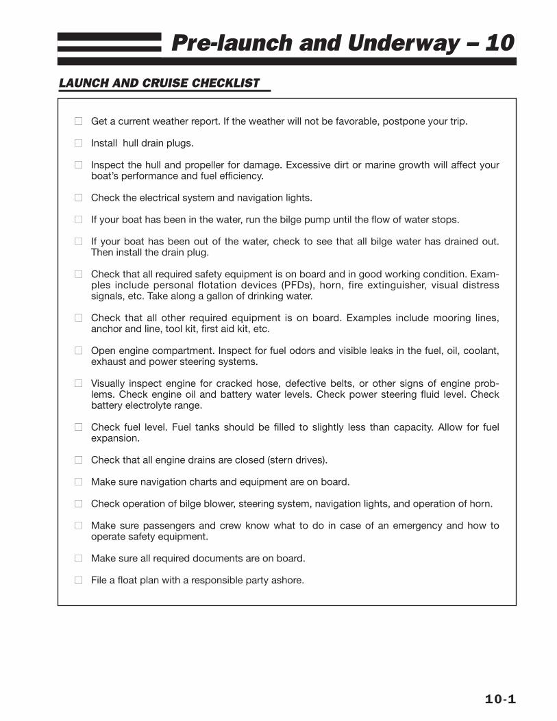
LAUNCH AND CRUISE CHECKLIST
10-1
Pre-launch and Underway – 10
■■ Get a current weather report. If the weather will not be favorable, postpone your trip.
■■ Install hull drain plugs.
■■ Inspect the hull and propeller for damage. Excessive dirt or marine growth will affect yourboat’s performance and fuel efficiency.
■■ Check the electrical system and navigation lights.
■■ If your boat has been in the water, run the bilge pump until the flow of water stops.
■■ If your boat has been out of the water, check to see that all bilge water has drained out.Then install the drain plug.
■■ Check that all required safety equipment is on board and in good working condition. Exam-ples include personal flotation devices (PFDs), horn, fire extinguisher, visual distresssignals, etc. Take along a gallon of drinking water.
■■ Check that all other required equipment is on board. Examples include mooring lines,anchor and line, tool kit, first aid kit, etc.
■■ Open engine compartment. Inspect for fuel odors and visible leaks in the fuel, oil, coolant,exhaust and power steering systems.
■■ Visually inspect engine for cracked hose, defective belts, or other signs of engine prob-lems. Check engine oil and battery water levels. Check power steering fluid level. Checkbattery electrolyte range.
■■ Check fuel level. Fuel tanks should be filled to slightly less than capacity. Allow for fuelexpansion.
■■ Check that all engine drains are closed (stern drives).
■■ Make sure navigation charts and equipment are on board.
■■ Check operation of bilge blower, steering system, navigation lights, and operation of horn.
■■ Make sure passengers and crew know what to do in case of an emergency and how tooperate safety equipment.
■■ Make sure all required documents are on board.
■■ File a float plan with a responsible party ashore.
FUELING
RECOMMENDATIONS
Although alcohol boosts the octane level ofgasoline, it also attacks the rubber fuel distribu-t ion l ines and even metal fuel systemcomponents. Alcohol will permeate most fuelhoses and other components such as fuelpump, gaskets and seals, and can also con-tribute to fuel system contamination.
The hoses we use in our boats are alcohol-resistant as are the materials used by theengine manufacturers. If only fuel containingalcohol is available, or the presence of alcoholis unknown, you must per form more frequentinspections for leaks and abnormalities. Anysign of leakage or deterioration requires yourimmediate attention. Refer to the engine manu-facturer’s recommendations on fuel type andoctane ratings.
PRELIMINARY GUIDELINES1. Safely secure your boat to the dock.
2. Close all hatches, windows, doors and com-partments to prevent accumulation of fuelvapors.
3. Ensure that a fire extinguisher is readilyavailable.
4. Do not store fuel in areas that are not ade-quately ventilated.
5. Use only fuel lubricants recommended bythe engine manufacturer.
PUMPING FUEL
1. Be sure to fuel in a well-lit area gasolinespills are unnoticeable under poor lighting orin the dark.
2. Remove the gas fill cover.
3. Insert the fuel supply nozzle, keeping it incontact with the fuel fill plate to guardagainst static produced sparks.
4. Stand away from the fuel tank vent and gasfill during fueling. Splashback may occur andcan be an eye irritant and/or a fire hazard.
5. Avoid spillage. Fuel spilled or pumped intothe water is harmful to fish and wildlife. Dis-charging fuel into the water contaminatesthe environment and violates the law. Wipeup any excess fuel immediately.
6. After pumping approximately 10 gallons offuel into the fuel tank, inspect the engineand fuel tank area for any signs of leakage.If no leaks or other problems are detected,resume fueling.
7. Allow space at the top of the tank for ther-mal expansion.
8. If fuel cannot be pumped in at a reasonablerate, check for fuel vent blockage or a kinkin the line.
10-2
Do not smoke, extinguish all openflames, STOP all engines and otherdevices that could cause sparks,including the bilge blower. Do not useelectrical switches or accessories.Shut OFF all stoves that may producea spark or flame. Close all openingsinto the cabin area of the boat.
WARNING!
When fueling or having your boatfueled by an attendant, be sure thewaste pump-out or fresh water fittingis not mistaken for the gas fill.
WARNING!
Follow engine manufacturer’s recom-mendations for types of fuel and oil.Use of improper products can damagethe engine and void the warranty.
CAUTION!
Fumes from rags used to wipe up fuelspills can explode if stored on theboat. Dispose of rags properly ashorebefore getting underway.
DANGER!
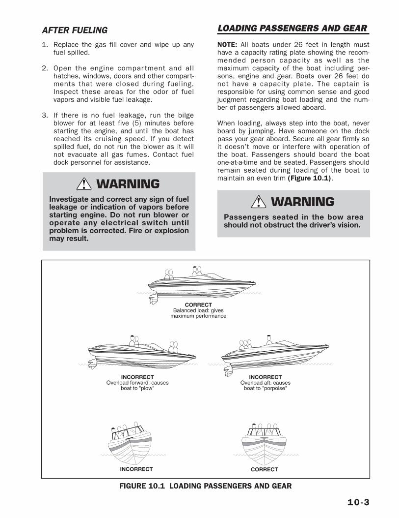
AFTER FUELING1. Replace the gas fill cover and wipe up any
fuel spilled.
2. Open the engine compar tment and allhatches, windows, doors and other compart-ments that were closed during fueling.Inspect these areas for the odor of fuelvapors and visible fuel leakage.
3. If there is no fuel leakage, run the bilgeblower for at least five (5) minutes beforestarting the engine, and until the boat hasreached its cruising speed. If you detectspilled fuel, do not run the blower as it willnot evacuate all gas fumes. Contact fueldock personnel for assistance.
LOADING PASSENGERS AND GEAR
NOTE: All boats under 26 feet in length musthave a capacity rating plate showing the recom-mended person capacity as well as themaximum capacity of the boat including per-sons, engine and gear. Boats over 26 feet donot have a capacity plate. The captain isresponsible for using common sense and goodjudgment regarding boat loading and the num-ber of passengers allowed aboard.
When loading, always step into the boat, neverboard by jumping. Have someone on the dockpass your gear aboard. Secure all gear firmly soit doesn’t move or inter fere with operation ofthe boat. Passengers should board the boatone-at-a-time and be seated. Passengers shouldremain seated during loading of the boat tomaintain an even trim (Figure 10.1).
10-3
Investigate and correct any sign of fuelleakage or indication of vapors beforestarting engine. Do not run blower oroperate any electrical switch untilproblem is corrected. Fire or explosionmay result.
WARNING!
CORRECTBalanced load: gives
maximum performance
INCORRECTOverload forward: causes
boat to "plow"
INCORRECTOverload aft: causes
boat to "porpoise"
INCORRECT CORRECT
FIGURE 10.1 LOADING PASSENGERS AND GEAR
Passengers seated in the bow areashould not obstruct the driver’s vision.
WARNING!
IMPORTANT: Passengers are prohibited fromriding on the bow with feet hanging over theside or ride while sitting on the stern, gunwalesor setbacks. The Coast Guard considers theseacts to be negligent or grossly negligent opera-tion. They are prohibited by law because fallsfrom moving boats are a major cause of fatalrecreational boating accidents.
IMPORTANT: The presence of the capacity platedoes not relieve the boat operator from theresponsibility of using common sense or soundjudgment. Turbulent waters and adverseweather conditions will reduce the maximumload capacity rating of the boat.
STARTING PROCEDURES
The operation and maintenance manual sup-plied with your engine provides pre-star t,starting and cold-starting instructions. The fol-lowing information is merely a guide and notintended to explain in detail all starting proce-dures and instructions. Refer to your engineowner’s manual.
PRELIMINARY CHECKS1. Secure boat to the dock before attempting
to star t engine. The boat should be keptsecure until the engine is running andwarmed up.
2. Operate the bilge pump until the flow ofwater stops.
3. Make sure the throttle is in the neutral posi-tion and stern drive or outboard is loweredinto water.
4. Make sure passengers seated in the bowarea do not obstruct the driver’s vision.
STARTING
1. Check all electrical systems and navigationlights.
2. If your boat is equipped with an optional bat-tery selector switch, turn the battery switchto 1, 2 or ALL position.
3. If your boat has fuel injection, turn the keyto start the engine. Engine will not turn overif throttle is not in the neutral position.
If your boat does not have fuel injection,depress the engine warmup button toadvance the throttle several times and leaveit in the SLOW/START position. This willactuate the carburetor accelerator pumpand feed fuel to the engine. Turn ignition keyto START position.
4. When engine is cold, run engine approxi-mately one (1) to two (2) minutes at fastidle speed (1200 to 1500 RPM). This stepis not necessary with fuel injected engines.
5. Once engine has warmed up, check watertemperature gauge to ensure engine temper-ature stays within optimum range. Iftemperature reading is abnormally high,stop engine immediately and inspect forcause of high reading.
6. With engine running, voltmeter should showa reading between 12 and 15 volts.
7. Check steering operation. Turn steeringwheel full to por t and starboard whileobserving outdrive movement.
8. Inspect for fuel odors and visible leaks inthe fuel, oil, coolant, exhaust and powersteering systems.
9. Make sure boat is securely moored to thedock and engine is idling. Then move thethrottle forward and then aft and back toneutral to check for proper operation of theshifting motion. Be careful. Leave theengine in gear for only a second or two.
10-4
To prevent excessive exposure andreduce the possibility of carbonmonoxide accumulation in the cabinand cockpit areas of the boat, theoperator should provide adequate ven-tilation in each of these areas. Utilizeall hatches, doors, windows and sidevents to increase air movement. SeeSection 2 for information about thedangers of Carbon Monoxide.
DANGER!
MANEUVERING
When all your pre-departure checks have beencompleted and the engine has warmed up, youwill be ready to leave the dock. Take intoaccount the amount of wind, tide current, andother forces that may affect your maneuveringas you leave the dock. Idle speeds work bestwhen maneuvering to and from the dock. Do notforget to release the mooring lines.
LEAVING THE DOCKYou are ready to leave the dock after the enginehas warmed up. Check all gauges for appropri-ate readings before casting off. If oil pressureis abnormally low or engine temperature isabnormally high, stop the engine immediately.Check voltmeter to be sure the charging systemis working properly. Check for fuel, oil, andexhaust leaks. Correct the cause of any abnor-mal condition before getting underway.
After making sure your boat is ready, checkwind, tide, current and other forces that willaffect the way you maneuver your boat awayfrom the dock. Throw mooring lines off to yourboat. Shift your boat’s engine into forward orreverse depending on whether you want to movethe bow or the stern away from the dock first.Run your engine at a slow speed as you moveaway from the dock. If you move the bow outfirst, watch that the stern of the boat does notswing into the dock or a piling.
Once away from the dock, devote some time tolearning how to maneuver. Practice dockingusing an imaginary dock. Practice stopping andreversing.
STOPPINGYou do not have brakes on a boat. Practicestopping maneuvers and learn early how yourboat reacts. From forward motion, pull the throt-tle back towards NEUTRAL. Depending on yourspeed, the distance the boat travels until itcomes to a complete stop will vary. The abilityto measure the distance will only be acquiredthrough experience.
Once the boat has slowed and motor is idling,place the shift in REVERSE. Gradually increasingreverse power with the throttle will allow you tostop the boat in a very short distance.
NOTE: A boat will not respond to steering inreverse nearly as well as it does when going for-ward, so do not expect to accomplish tightturning maneuvers when backing up.
Remember that all boats steer by the stern (thefeeling is much like steering your automobile inreverse). This means that the stern of your boatwill swing in the direction opposite to your turn.For example, when you turn the helm wheel tothe left, the stern of your boat will swing in thedirection opposite to your turn. This is espe-cially important to keep in mind when docking,operating in close quarters with other boats, orwhen approaching a swimmer or downed skierin the water.
Once you have spent enough time practicingmaneuvers and have a feel for how the boat han-dles, you will be ready to run in open waters.
ACCELERATION
10-5
Boat steering is not self-centering.Steering is affected by engine and pro-peller torque, trim tab setting, waveand current action and the speed ofthe hull through the water. Constantattention to steering is required forsafe operation.
WARNING!
Make sure passengers sitting in thebow area do not obstruct the opera-tor’s vision when casting off or whileunderway.
WARNING!
Before accelerating be sure your pathis clear; the bow will rise and momen-tarily obstruct forward vision. Makeyour passengers aware of your inten-tion to accelerate.
WARNING!
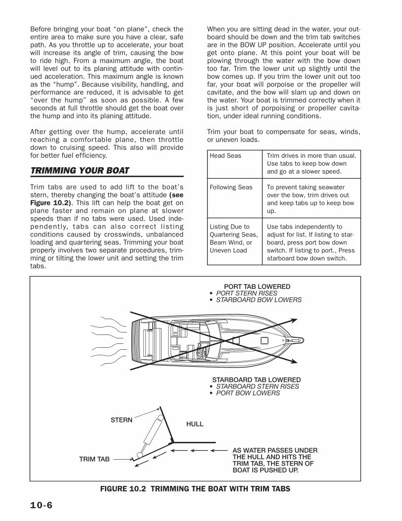
Before bringing your boat “on plane”, check theentire area to make sure you have a clear, safepath. As you throttle up to accelerate, your boatwill increase its angle of trim, causing the bowto ride high. From a maximum angle, the boatwill level out to its planing attitude with contin-ued acceleration. This maximum angle is knownas the “hump”. Because visibility, handling, andperformance are reduced, it is advisable to get“over the hump” as soon as possible. A fewseconds at full throttle should get the boat overthe hump and into its planing attitude.
After getting over the hump, accelerate untilreaching a comfor table plane, then throttledown to cruising speed. This also will providefor better fuel efficiency.
TRIMMING YOUR BOAT
Trim tabs are used to add lift to the boat’sstern, thereby changing the boat’s attitude (seeFigure 10.2). This lift can help the boat get onplane faster and remain on plane at slowerspeeds than if no tabs were used. Used inde-pendently, tabs can also cor rect l ist ingconditions caused by crosswinds, unbalancedloading and quartering seas. Trimming your boatproperly involves two separate procedures, trim-ming or tilting the lower unit and setting the trimtabs.
When you are sitting dead in the water, your out-board should be down and the trim tab switchesare in the BOW UP position. Accelerate until youget onto plane. At this point your boat will beplowing through the water with the bow downtoo far. Trim the lower unit up slightly until thebow comes up. If you trim the lower unit out toofar, your boat will porpoise or the propeller willcavitate, and the bow will slam up and down onthe water. Your boat is trimmed correctly when itis just short of porpoising or propeller cavita-tion, under ideal running conditions.
Trim your boat to compensate for seas, winds,or uneven loads.
10-6
STARBOARD TAB LOWERED• STARBOARD STERN RISES• PORT BOW LOWERS
PORT TAB LOWERED• PORT STERN RISES• STARBOARD BOW LOWERS
STERN
TRIM TAB
HULL
AS WATER PASSES UNDERTHE HULL AND HITS THETRIM TAB, THE STERN OFBOAT IS PUSHED UP.
FIGURE 10.2 TRIMMING THE BOAT WITH TRIM TABS
Head Seas Trim drives in more than usual.Use tabs to keep bow downand go at a slower speed.
Following Seas To prevent taking seawaterover the bow, trim drives outand keep tabs up to keep bowup.
Listing Due to Use tabs independently toQuartering Seas, adjust for list. If listing to star-Beam Wind, or board, press port bow down Uneven Load switch. If listing to port., Press
starboard bow down switch.

Remember that most boats react very slowly totrim tabs. Often boat owners do not give trimtabs time to work. Press the trim tab switchesfor only two seconds at a time and then allowsome time for the boat to react. If the boat isstill listing after a minute or two, press the trimtab switch again for a two second interval. Thelabels on the trim tab switches indicate whatyou want your boat to do, not what you want thetabs to do.
It is a good idea to take your boat out onto openwater shortly after you get it and experimentwith the trim tabs. After you get your boat ontoplane, set the tabs in various positions andnote how your boat reacts. This will give you afeel for the trim tabs work.
It is possible to extend the cyl inder l i feexpectancy on your trim tabs. To do this, keepthe cylinders retracted while at dockside. Pressboth trim tab controls down until tabs reachtheir full up position.
TILT/TRIM CONTROL SWITCHESNOTE: Trim refers to the angle of the lower unitor outboard motor in relation to the bottom ofthe boat. With respect to trimming, the wordsin, down, under, and forward, have the samemeaning as do up, out, and aft.
1. The standard trim control switch is locatedon the control lever handle.
10-7
DN TRIM UP
DN TRIM UPTRIM
TRIM
TRIM
INCORRECTCauses boat to "plow"
CORRECTGives maximum performance
INCORRECTCauses boat to "porpoise"
DN TRIM UP
FIGURE 10.3 TRIMMING THE BOAT OUTDRIVE
2. The switch controls the position of the sterndrive or outboard motor. Proper trim is veryimportant in boating.
3. In the case of low or heavy bow attitude,the boat tends to “plow” (Figure 10.3).The lower unit is trimmed too far under orforward. Trim the unit UP (out) to correctthis situation.
4. If the bow is too high, the boat tends to“porpoise” (Figure 10.3). The drive unitis trimmed up or out too far. Trim DN (in)to correct.
5. A good practice is to get underway (espe-cially when fully loaded or pulling a skier)with the unit trimmed all the way DN (under).After the boat is on plane, adjust the trimout slightly to obtain the proper bow attitudeand engine speed.
6. Trim also af fects propeller selection andfuel ef f iciency. Al l models should be“propped” to be in the upper half of themaximum RPM range with the boat lightlyloaded and the drive trimmed up to maxi-mum. This configuration allows the engineto operate within the recommended RPMrange with a heavy load.
The power unit should never be trimmed upto a point where the propeller cavitates (orslips). A rapid increase in engine RPM’s isevidence of cavitation. If this occurs acci-dentally while running at full throttle,immediately lower the drive trim and reducethe throttle until the slipping stops. If neces-sary, have your dealer reset the trim limitswitch (if provided) to avoid overtrimming inthe future.
If the prop slips at lower planing speeds,the drive may be trimmed too high. Immedi-ately lower the drive unit until the prop grabsagain to restore efficiency.
7. Trimming out, in addition to raising the bow,also lifts the boat higher, gaining speedbecause less hull is in the water.
8. Raise tabs all the way up when coming offplane. Retrim boat when accelerating again.Readjust tabs if necessary to compensatefor new direction of wind or seas.
9. The trailering position of some stern drivesis controlled by a separate switch on thedash switch panel or throttle/shift control.Do not activate this switch while engine isrunning. Doing so can severely damage thelower unit and engine.
NOTE: Refer to the control instructions regardingthe power trim controls installed on your boat.
EXCESSIVE NOISE
Remember to be a good boating neighbor.Sounds can carry a long distance over water,especially at night. Loud conversations andmusic can be disturbing to others as can exces-sive engine noise. Check with local authoritiesregarding any noise restrictions.
ANCHORING
1. The weight of the anchor and diameter ofanchor line should be governed by the sizeand weight of your boat. Get advice fromyour dealer before you buy an anchor.
2. Keep anchor secure while underway to pre-vent damage or injury due to sudden shiftingin the boat’s attitude.
3. Use two or more anchors if anchoringovernight or for extended periods. If notusing two anchors, make cer tain there issufficient clearance for your boat to swing ina full circle to prevent damage in case ofshifting winds.
4. Make certain you have enough anchor line(or scope) for the depth of water. Youranchor line should be 6 to 7 times thedepth of water anchored in. For example, ifyou are in 20 feet of water, use 120 to 140feet of anchor line.
DROPPING ANCHOR1. Have a crew member carefully lower the
anchor. Keep slight tension on the anchorline while lowering and maintain your ten-sion after reaching the bottom.
10-8
Secure anchor line only to bow eye ordeck cleat. Never tie anchor line to arail, rail fitting or other hardware notdesigned to support this stress.
CAUTION!
2. Maneuver the boat slowly backwards untillength of anchor line is 6 or 7 times thedepth of the water.
3. Fasten the anchor line around the bow eyeor deck cleat. Anchor flukes should dig inand catch. Watch for anchor drag by check-ing shoreline landmarks at the time theanchor is dropped and one-half hour later. Ifthe boat has drifted away from these refer-ence marks, the anchor is dragging andmust be reset.
WEIGHING1. Start the engine running before pulling in
anchor.
2. Slowly maneuver the boat forward to reducetension on the line and make retrieval of theanchor line easier.
3. Pull in anchor line until the line is vertical.Pull firmly to lift the anchor’s shank and freethe flukes from the bottom.
If the anchor becomes stuck, attach the verticalline to the mooring cleat. Wave action on thebow may lift flukes from the bottom and free theanchor. If the anchor is still stuck, feed out afew feet of line and attach it to the bow cleat.Maneuver the boat around the anchor, keepingthe line firm. Determine the angle that will workto pull the anchor free.
Anchors are available in different shapes, sizesand weights to fit dif ferent boats, uses, andconditions. Your dealer can tell you whichanchor will work best for your boat.
NAVIGATION LIGHTS
Although night activities are limited, cruising atnight can be very pleasurable. It can also bedangerous if you don’t pay close attention towater levels and obstacles. Be especially care-ful of shallow waters and watch for submergeddebris, rocks and other obstacles in the water.Your navigation lights are intended only to pre-vent collision, not to improve your night vision.You may choose to use a spotlight instead.
NOTE: It is illegal to use your spotlight as aheadlight. Use it only temporarily to check theposition of your boat and the surrounding area.
Your boat has one white (stern), one red (port)and one green (starboard) light. The stern lightmay be a removable pole light. To use the light,
line up the two-prong plug in the pole with thereceptacle in the base. Plug the light in, andlock it into place with lever/slide lock. When notin use, stow the light inside your boat for safe-keeping. This light can be turned on or off atthe helm.
Check lights for proper operation before headingout at night. You should also learn to identifythe running light combinations for other ves-sels. We recommend that you participate in aboating safety course to further learn about nav-igation lights and safe boating practices.
The anchor lights and navigation lights are con-trolled by a switch at the helm. The anchor lightswitch allows you to turn on just the stern(white) light when anchored or moored. Whileunderway, use the navigation light switch to turnon the stern (white), port (red) and starboard(green) lights. Lights are off when switches arein the OFF position.
HAZARDOUS CONDITIONS
STORMSStorms sometimes appear without advancenotice. Although weather information from mete-orological observation and reporting stations isavailable, weather bureaus are known to havefailures in their predictions or information gath-ering equipment. There is no substitute for astrong understanding of what action to takewhen the weather takes a turn for the worst.Many marinas fly weather signals. You shouldlearn to recognize these signals and monitoryour local weather forecasts before leaving port.
The present and forecasted weather conditionsare of primary consideration, but a threat ofpossible storms should always be a concern.Observance of the following information willhelp in your safety afloat if storms do occur:
• Keep a watch on the horizon for approachingstorm indicators.
• Turn radio ON. Dial in local weather stationand monitor forecast. If your boat has a VHFradio, check the weather channels.
• The best possible situation is to return to asafe port if time allows.
• Close and secure all portals and hatches.Stow all loose gear below deck and tie downany gear required to remain on deck.
10-9
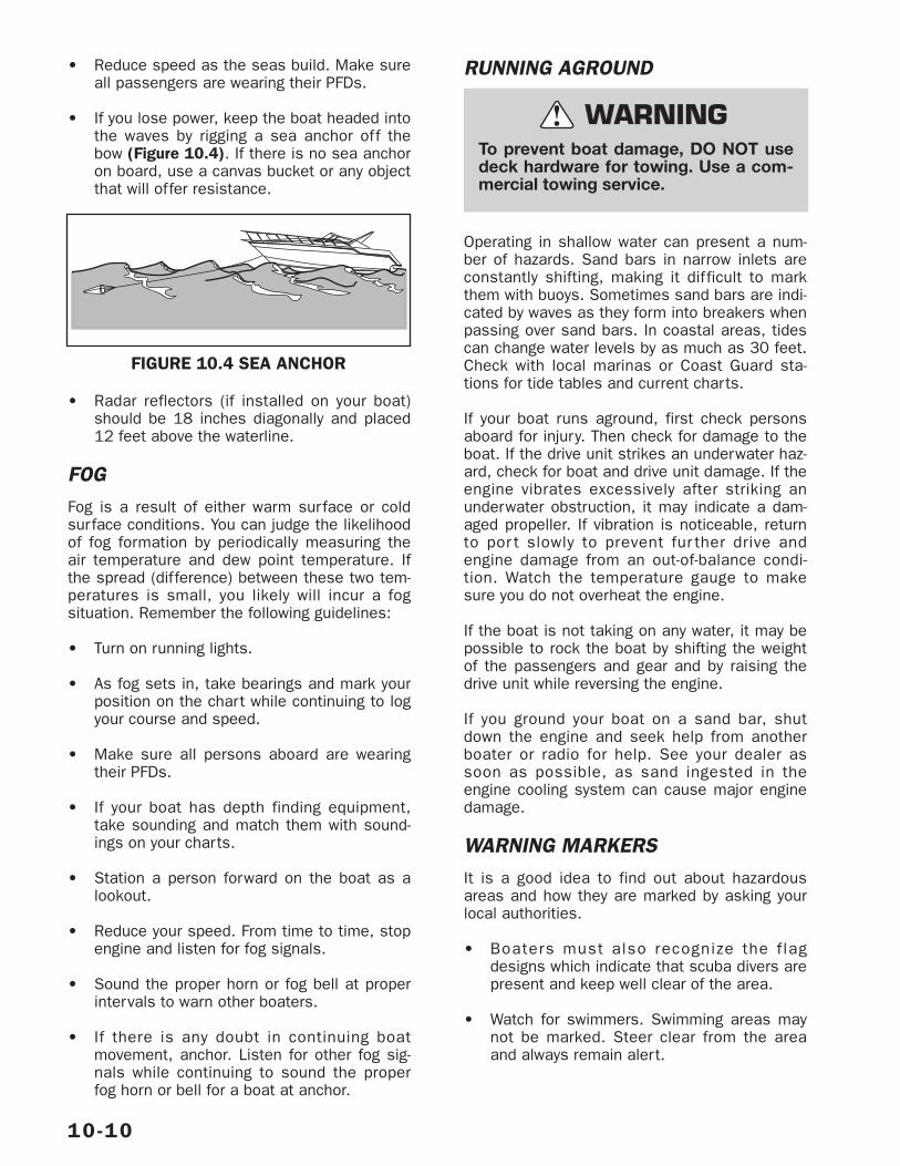
• Reduce speed as the seas build. Make sureall passengers are wearing their PFDs.
• If you lose power, keep the boat headed intothe waves by rigging a sea anchor off thebow (Figure 10.4). If there is no sea anchoron board, use a canvas bucket or any objectthat will offer resistance.
• Radar reflectors (if installed on your boat)should be 18 inches diagonally and placed12 feet above the waterline.
FOGFog is a result of either warm surface or coldsurface conditions. You can judge the likelihoodof fog formation by periodically measuring theair temperature and dew point temperature. Ifthe spread (difference) between these two tem-peratures is small, you likely will incur a fogsituation. Remember the following guidelines:
• Turn on running lights.
• As fog sets in, take bearings and mark yourposition on the chart while continuing to logyour course and speed.
• Make sure all persons aboard are wearingtheir PFDs.
• If your boat has depth finding equipment,take sounding and match them with sound-ings on your charts.
• Station a person forward on the boat as alookout.
• Reduce your speed. From time to time, stopengine and listen for fog signals.
• Sound the proper horn or fog bell at properintervals to warn other boaters.
• If there is any doubt in continuing boatmovement, anchor. Listen for other fog sig-nals while continuing to sound the properfog horn or bell for a boat at anchor.
RUNNING AGROUND
Operating in shallow water can present a num-ber of hazards. Sand bars in narrow inlets areconstantly shifting, making it difficult to markthem with buoys. Sometimes sand bars are indi-cated by waves as they form into breakers whenpassing over sand bars. In coastal areas, tidescan change water levels by as much as 30 feet.Check with local marinas or Coast Guard sta-tions for tide tables and current charts.
If your boat runs aground, first check personsaboard for injury. Then check for damage to theboat. If the drive unit strikes an underwater haz-ard, check for boat and drive unit damage. If theengine vibrates excessively after striking anunderwater obstruction, it may indicate a dam-aged propeller. If vibration is noticeable, returnto por t slowly to prevent fur ther drive andengine damage from an out-of-balance condi-tion. Watch the temperature gauge to makesure you do not overheat the engine.
If the boat is not taking on any water, it may bepossible to rock the boat by shifting the weightof the passengers and gear and by raising thedrive unit while reversing the engine.
If you ground your boat on a sand bar, shutdown the engine and seek help from anotherboater or radio for help. See your dealer assoon as possible, as sand ingested in theengine cooling system can cause major enginedamage.
WARNING MARKERSIt is a good idea to find out about hazardousareas and how they are marked by asking yourlocal authorities.
• Boaters must also recognize the f lagdesigns which indicate that scuba divers arepresent and keep well clear of the area.
• Watch for swimmers. Swimming areas maynot be marked. Steer clear from the areaand always remain alert.
10-10
To prevent boat damage, DO NOT usedeck hardware for towing. Use a com-mercial towing service.
WARNING!
FIGURE 10.4 SEA ANCHOR
• Distress flags indicate a fellow boater is inneed of assistance.
• Navigation markers ser ve as a means ofidentifying navigable routes and indicatewater hazards. Boaters should becomefamil iar with navigation markers andstay within marked boundaries and clearof hazards.
REACTING TO EMERGENCIES
Be prepared to deal with emergencies beforethey happen. Try to formulate a plan for eachtype of emergency in advance so that decisionscan be made quickly and without hesitation.Precious moments lost can mean the differencebetween losing and saving a life.
FLOODINGIf your boat starts taking on water, activate thebilge pump immediately. Make sure all passen-gers are wearing their PFDs. Open the enginecompartment, look for the cause of the flood-ing. Check all hoses, through hull fittings, seacocks and strainers. If flooding occurs as aresult of collision or grounding damage, call forassistance and head for shore if possible.
CAPSIZING AND MAN OVERBOARDBy far, the largest number of boating fatalitiesinvolve capsizing and falling overboard acci-dents. By being prepared ahead of time with anappropriate plan of action, you can greatly loweryour chances and your passengers’ chances ofbecoming seriously injured.
CAPSIZINGWear PFD’s or have them readily available at alltimes. If your boat capsizes, and others were onboard, locate them and guide them to the safetyof the hull. Even if the boat floats in an upside-down position, stay with it. The boat hull ismuch easier for rescuers to spot than a humanhead sticking out of the water. DO NOT attemptto swim ashore, it may be further than it looks.
MAN OVERBOARDThink through and follow these procedures ifsomeone in your boat falls overboard.
• Remember, every second counts, you mustact fast.
• Move throttles to idle position immediatelyand yell “MAN OVERBOARD.”
• Throw some floating object overboardimmediately. Keep your required TypeIV PFD accessible at all times for suchan emergency.
• Keep the person in the water in sight at alltimes. Have a passenger do nothing butwatch the person. Do not go into the waterto help the victim. One person in the wateris enough trouble.
• Circle around quickly, approaching into thewind and waves. When the person is along-side, put the engine in neutral and throwthem a Type IV PFD with a line attached orextend a paddle or boat hook within his/herreach.
COLLISIONIf a serious collision occurs, you should firstcheck the condition of all passengers aboard,then inspect your boat to determine the extentof damage.
1. Make sure all persons aboard are wearingtheir PFDs.
2. If you need help and your boat has a ship-to-shore radio, first contact the U.S. CoastGuard (VHF Channel 16) or other rescueauthorities immediately.
3. Prepare to assist the other vessel unlessyour passengers and/or boat are in danger.
4. If the bow of the other boat penetrated yourboat’s hull, prepare to block the openingonce the boats are separated.
5. Shore up the hole with a spare PFD or bunkcushion from your boat.
6. While blocking the hole, trim the boat sothat the hole is out of the water.
FIREMost fires are caused by electrical problems orcareless fueling practices. A fire on board yourboat is a serious emergency. You must workquickly to implement safety procedures. If a fireoccurs, immediately stop the engine.
1. Make sure all persons aboard are wearingtheir PFDs.
10-11
2. If the fire is small, attempt to put it out withyour fire extinguisher. If the fire is in theengine compar tment, turn of f the bilgeblower. Do not open the engine compar t-ment. This feeds oxygen to the fire and maycause it to flare up.
3. If the fire gets out of control, execute a dis-tress signal and call for help if equippedwith a ship-to-shore radio.
4. All persons aboard should jump overboardand swim a safe distance away from theflames.
IMPORTANT: All persons aboard should knowthe location and proper operation of the fireextinguishers.
Guidelines
• Use only approved marine cooking andheating systems.
• Open flames demand constant attention.
• Keep flammable materials in approved con-tainers in a overboard vented locker sealedfrom the interior of the boat.
• Ensure venti lation systems are unob-structed.
• Remove mooring covers before star tingengine.
• Check the bilge for fuel leaks.
• Extinguish smoking materials carefully.
• Use special care with flame or high tempera-tures around urethane foam.
• Check cleaning products for flammability.
• Ventilate when cleaning or painting.
• Disconnect electrical system from its powersource before performing maintenance.
• Replace breaker or fuse with same amper-age device.
• Electrical appliances must be within ratedamperage of boat circuits. Observe the boatcarefully while the electrical system is beingenergized.
• Allow only a qualified marine electrician toservice the boats electrical system.
MEDICAL EMERGENCYAccidents while boating can and may happen.Be prepared to handle these emergencies whenthey happen. Keeping a first aid kit and dr yblankets on board can assist during these situa-tions. It is also a good idea to contact your localRed Cross for information and training on firstaid and CPR.
PROPULSION FAILUREBefore you call for help regarding an engine ordrive unit failure, it is a good idea to eliminatethe possibility of simple problems. Turn off theengine and check to see that (1) there is fuel inthe tank; (2) the engine cooling intakes on theoutdrive are not clogged; (3) props are cleanand free of weeds, netting, etc.; (4) no hosesare leaking; (5) there is oil in the engine.
Once you have checked out the possibilitieslisted above and find they are not the problem,call for help giving your position and a detaileddescription of your boat.
CONTROL FAILUREIn the unlikely event of a throttle/shift failure,shut down the engine immediately. Carefullycheck the control connections in the enginecompartment to see if they are secure. If not,tr y to locate the attaching hardware andreassemble. If that is not possible, try to usewhatever is available such as paper clips, hairclips, tape, etc., to secure the connections. If atemporary repair is made, return to port at theslowest steerable speed and be prepared totake emergency action should the temporaryrepair fail also. Have your dealer make repairsbefore using the boat again.
STEERING FAILUREIf a problem with the steering occurs, shut downthe engine immediately. Check the connectionsto the outboard motor or drive unit in the enginecompar tment. Some boats have a push/pullcable while others will have hydraulic hose con-nections. With cable connections, check theattaching hardware and tighten it if necessary. Ifyou have hydraulic hose connections, check tosee if they are leaking. If so, tighten the connec-tions and check the hydraulic fluid reservoirlevel. Most stern drives are power assisted and
10-12
have their own hydraulic reservoir and enginemounted drive pump; check the level of reser-voir and drive pump belt. If the steering is notoperating properly, do not operate the boat andcall for assistance.
ADDITIONAL UNDERWAYINFORMATION
• Always be aware of local laws on noise lim-its. Noise means engine noise, radio noiseor even yelling by people on your boat. Goodseamanship demands that you operate yourboat quietly so as not to infringe on therights of others. Don’t use the thru-transomexhaust unless you are well off shore.
• You are responsible for any damage or injurycaused by your boat’s wake. Observe nowake speed zone warnings. Operate yourboat with regard for the safety of otherboats and people in your boating area.
• Keep your engine well tuned to decreaseexhaust hydrocarbon emissions that pollutethe air and water.
RETURNING TO SHORE
DOCKINGAlways approach the dock slowly. Think beforeacting. If you are wondering whether your boatwill fit in a space against a dock, remember thatpilings are often (but not always) spaced 10feet apart.
Remember that it is easier to control a boat inreverse because a boat steers from the stern.When backing into a slip, back so that bowswings into the wind if possible. You will havemore control.
If you have a twin engine boat, center the steer-ing wheel. Use the throttles and shifters tocontrol the boat’s movement.
If possible, come in against the wind or current,whichever is stronger. Approach the dock at a30-45° angle. As the boat nears the dock,slowly swing parallel to it. Tie the bow line first;then the stern.
If wind or current is moving toward the dock,move parallel to the dock further out. Let thewind or current push you in. Tie the stern first,then the bow.
Use extreme caution if wind or current is fromyour stern. Back in towards the dock slowly at aslight angle with engine in slow reverse. Gentlyswing parallel. Tie stern first, then the bow.
If the weather looks bad, use spring-lines fromthe bow and stern to dock amidships of theboat. Tie up on the downwind side of the dock.If the wind is changeable, place fenders overthe side between the boat and the dock.
MOORINGAfter you have positioned your boat next to thedock, you must secure it with mooring lines tokeep it in position. Mooring lines must be longenough to secure your boat in any docking situa-tion. For example, the length of the lines for a16-foot runabout should be at least 15 feet. Aneye splice at the end of each line works wellwith bow or stern cleats.
The mooring lines you will use most often arethe bow line, the stern line, and spring lines asshown on Figure 10.5. Each line has a specificpurpose. The bow line and the stern line secureyour boat’s bow and stern. The two spring lineskeep your boat from moving forward or back-ward when you are moored alongside a dock.
If you are mooring your boat for a short time,bow and stern lines may be the only lines youwill need. If you are mooring your boat for alonger time or the currents are swift, you shoulduse spring lines. The stern spring line leadsfrom the boat’s stern cleat forward to the pilingor cleat on the dock. The bow spring line leadsfrom the bow cleat aft to the dock.
If you are mooring your boat in a slip, bow andspring lines, port and starboard, will keep yourboat in position.
NOTE: If tides are a consideration, be sure toleave slack in the lines to make up for the riseand fall of the water while your boat is docked.
10-13
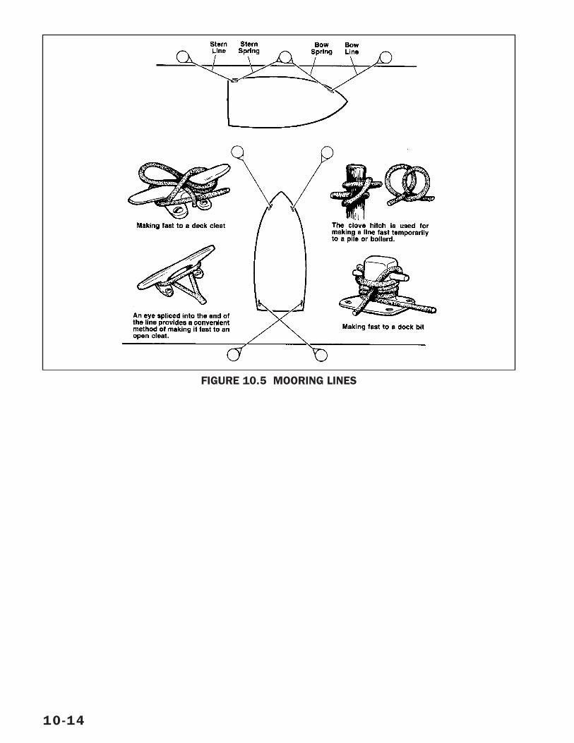
10-14
FIGURE 10.5 MOORING LINES
If properly used and maintained, your boat will giveyou years of use and enjoyment. By keeping yourboat “ship shape,” you will be doing more thanprotecting your investment; you will also ensuregood performance and safety on the water.
When cold weather has arrived or a change inyour boat’s usage requires extended storage,we suggest that you use the following guide-lines. Special preparations are necessary toprevent damage by rust and corrosion, mildew,discharged batteries, and freezing water. If youlive in an area that does not require seasonalstorage, we recommend a thorough inspectiononce a year.
IMPORTANT: Your warranty does not cover dam-age to your boat if it is not properly stored andwinterized. We recommend that, at a minimum,you check with your dealer about proper winteri-zation procedures. Better yet, have your dealerprepare your boat for storage for you.
LIFTING THE BOAT
Unless your boat is trailerable, have your dealeror qualified marina personnel lift your boat outof the water for you. Each boat has main framecomponents designed to support the boat whenit is being lifted out of the water. Severe gelcoatcrazing or more serious hull damage can occurif the lifting slings exert pressure on the gun-wales. Flat, wide belting-type slings should beused. Don’t use cable-type slings. The spreaderbar at each sling should be as long as the dis-tance across the widest point the sl ingsurrounds.
• Never hoist the boat with more than a mini-mal amount of water in the bilge.
• Empty fuel and water tanks, especially ifthey have large capacities.
• Larger boats that are not normally trailera-ble have sling placement labels on the sidesof the boat. Be sure to position slings asindicated by the labels.
• Do not place the slings where they may lifton the propeller shaft or underwater fittings.
• Do not use deck cleats or bow or stern eyesfor lifting unless they are labeled.
CRADLEA cradle is the ideal support for your boat when-ever it is not in the water. Properly designed andlocated, the cradle will support the boat underthe main frames. Suppor t at these points isessential for preventing damage to the hull. Pur-chase a cradle from your dealer to ensure thatyour boat has the correct support.
PREPARATION FOR STORAGERemove the bilge drain plug immediately aftertaking the boat out of the water. Store the plugin a plastic bag and tape it to the throttle con-trol lever so that it can easily be found.
After washing the boat, raise the bow out of thewater high enough to allow as much water aspossible to drain while you are completing otherstorage preparations. Before covering your boat,apply a coat of Meguiar’s Boat/RV Wax to pre-vent excessive oxidation.
TRAILERPer form the following steps to winterize yourtrailer for storage.
• Check tire inflation.
• Clean and repack the wheel bearings. Makesure there is no water in the wheel hubs.Inspect the bearings and races for pitting.Inspect the grease seals for wear. Replace ifnecessary and fill the bearings with grease.
• Examine the entire trailer and running gearfor signs of cracking or metal fatigue. Repairweld cracks, and tighten any loose bolts andscrews.
• Check the frame. Make sure there areno signs of bending or swaying due tooverloading.
• Repair or replace worn or misadjustedbunks or rollers.
• If rust has formed on the trailer, remove itby sanding and paint the bare spots tomatch the trailer.
11-1
Winterization and Commissioning – 11
• Inspect and adjust the brake system accord-ing to the manufacturer’s recommendations.Look inside brakes for excessive rust.
• Lubricate the winch, the coupler, all rollersand pivot points.
• Check the safety chains.
• Inspect the winch and fastening hook forwear.
• Check tie-downs for fraying. Loosen orremove tie-downs.
• Check the electrical system for wear orloose connections, and repair if necessary.
• Open tail light lenses and inspect bulbs andsockets for excessive rust and corrosion.Coat metal base of bulb with a die-electricgrease or spray with WD-40.
• If storing your boat on a trailer, make surethat the trailer supports are aligned with thestructural members of the hull. Distributethe weight properly. Make sure your boat iswell suppor ted across the transom andkeel.
• Put the rig on blocks or else move the trailerfrom time to time to prevent flat spots onthe tires.
• Position your boat’s bow to allow water todrain via the transom drain. Do not allowrain water to collect inside the boat.
• If it is possible for water to accumulate onthe boat covers, poke a small hole near theback of your boat cover canvas. Prepare thehole with a grommet to prevent tearing. Ifyour boat is tilted backwards, rain water willrun through the hole and out the bilge drainhole.
HULL• If your boat is going to be placed in dry stor-
age, as soon as the boat is hauled out,scrape off any barnacles and other growth ifnecessary. Scrub the hull and deck thor-oughly to remove marine growth and scum.(The hull is easiest to clean when the boatis first hauled out and while the adheringmaterial is still wet.)
• Inspect the underwater gear and propellersfor excessive wear or damage.
DECK• Wash the deck, superstructure, and/or
cockpit, clean all chrome and coat with arust inhibitor before storing.
• Clean the indoor/outdoor carpet.
ENGINE, SYSTEMS & COMPONENTS
ENGINE AND OUTDRIVEHave your dealer prepare the engine and out-drive for winter storage. Your dealer will servicethe cooling system as part of the engine winteri-zation. Special skills, tools, and equipment arerequired.
IMPORTANT: In regions where temperatures fallbelow freezing, all water in the engine must beremoved or replaced with a marine antifreezesolution before storing your boat for the winter.Mix antifreeze according to label directions forthe lowest expected temperature. Use non-toxicantifreeze to prevent damage to the environ-ment. Failure to do so will seriously damage theengine. Freeze damage is not covered by thewarranty. Make sure your boat’s engine isslightly bow up during the extended storageperiod.
FUEL SYSTEMFill the fuel tank to minimize condensation. Iftank is completely filled, fuel may overflow fromthe tank during weather. Help prevent damage tothe environment. Leave enough space for fuel toexpand. Add a gasoline stabilizer solution to thefuel prior to storage. Follow the stabilizer manu-facturer’s recommended procedure.
BATTERIES
11-2
To prevent personal injury, wear gog-gles, rubber gloves and a protectiveapron when working with battery. Bat-tery electrolyte can cause severe eyedamage and burns to the skin. In caseof spillage, wash area with a solutionof baking soda and water.
WARNING!
When working on or around battery connections,do not allow metal tools or loose wires to con-tact terminals. Contact across positive (+) andnegative (-) terminals will cause a short circuit.Electrical burns or personal injury may result.
• Remove the batteries. Check water leveland store away from freezing temperatures.
IMPORTANT: Batteries should be stored in acool, dry place.
• Clean outside battery case, terminals andbatter y clamps with a solution of bakingsoda and water.
NOTE: Do not allow baking soda/water solutionto enter the cells.
• Lightly sand battery posts and clamps withfine grit emery cloth.
• Apply a light coat of petroleum jelly to coverthe end of the battery cables.
• A monthly recharge or continuous tricklecharge should be applied to the battery dur-ing storage.
FRESH WATER SYSTEMWater must be removed from the fresh watersystem to prevent damage to system compo-nents during cold weather.
1. Turn on fresh water pump.
2. Open faucets and allow pump to emptyfresh water tank.
3. Close faucet when tank is empty. Shut offwater pump.
4. Mix nontoxic antifreeze in accordance withmanufacturer recommendations and addto f resh water tank. The amount ofantifreeze mixed should be equivalent tothe capacity of the water heater plusapproximately 2 gallons.
Note: Nontoxic antifreeze in fresh water tankwill also be needed to winterize head andmacerator.
5. Turn on water pump.
6. One by one, open each cold water faucetand fresh water outlet beginning with theone fur thest from the water tank. Close
faucet or outlet when antifreeze star ts toflow. (See icemaker manual for winterizationinstructions.)
7. One by one, open each hot water faucetbeginning with the one fur thest from thewater heater. Close faucet when antifreezestarts to flow.
8. Winterize remaining system componentssuch as shower and icemaker. (See ice-maker manual for winterization instructions.)
9. Shut off water pump
VACUFLUSH® SYSTEMThe fresh water system must be winterizedbefore winterizing the waste system. Refer tothe VacuFlush System manual for additionalinformation.
1. Have holding tank pumped out at anapproved pumpout station.
2. If necessary, add nontoxic antifreeze to freshwater tank. Mix antifreeze in accordance withthe manufacturer’s recommendations.
3. Operate head until antifreeze flows intobowl. Allow sufficient time between flushesfor vacuum to build up before flushing.
4. Operate macerator until antifreeze flowsthrough discharge fitting on side of hull.Flush head as needed to provide enoughantifreeze to winterize macerator.
5. Dispose of antifreeze according to manufac-turer’s instructions.
RAW WATER SYSTEMWater must be drained from the raw water sys-tem to prevent damage to seacock and waterlines.
1. Locate hose that connects raw water pumpwith raw water through hull pickup fitting,and close seacock.
2. Disconnect hose at the point that it con-nects with the through hull fitting.
3. Mix one gallon of non–toxic antifreeze mixedin accordance with the manufacturer’s rec-ommendations. Place end of hose inantifreeze.
11-3
Attach a hose to the cockpit washdownhose connector.
4. Position an empty container to catch theflow of antifreeze from cockpit hose.
5. Operate raw water system pump by turningon the raw water washdown switch at thehelm.
6. When antifreeze flows through hose intocontainer, shut off pump.
7. Repeat for foredeck washdown.
8. Reconnect the hose to the through hull fit-ting, and close the seacock.
9. Dispose of unused antifreeze according tomanufacturer’s instructions.
10.After boat has been lifted from water, openseacock so water can drain from valve. Donot open seacock while boat is in the water.
IMPORTANT: During commissioning, be sure toclose raw water system seacock before loweringyour boat into the water.
RAW WATER HOSESWater must be drained from engine coolinglines to prevent damage to seacock, seastrainer, and hoses. Refer to the engine manu-facturer’s manual for detai led enginewinterization procedures.
1. Open seacock valve and allow water todrain.
2. Disconnect hose at engine and lift hose upso water drains from hose.
3. Open petcock at bottom of sea strainer andallow water to drain. Have a suitable con-tainer to catch water as it drains fromseacock.
4. If your boat is out of the water, leave sea-cock open and hose disconnected.
IMPORTANT: During commissioning, be sure toclose engine seacocks and connect hosesbefore lowering your boat into the water.
AIR CONDITIONING SYSTEMWater must be drained from air conditioninglines to prevent damage to seacock, seastrainer, and air conditioning system compo-nents. Refer to the manufacturer’s manual fordetailed winterization procedures.
1. Open seacock valve and allow water todrain.
2. Close seacock. Seacock must remainclosed while winterizing the air conditioningsystem.
3. Open sea strainer by unscrewing wing nutson top of the strainer housing. Removescreen.
4. Mix 2-3 gallons of nontoxic antifreezeaccording to manufacturer’s directions.
5. Fill sea strainer housing with antifreeze.
6. Operate air conditioning pump. Refill seastrainer with antifreeze as level in strainergoes down.
7. Continue to operate pump until antifreezeflows out of thru–hull fitting.
8. Shut off air conditioning pump.
9. Close sea strainer and tighten wing nuts.
10.Open seacock to allow any water trapped invalve to drain. If your boat is out of thewater, leave seacock open.
11.Dispose of unused antifreeze according tomanufacturer’s instructions.
IMPORTANT: During commissioning, be sure toclose air conditioning seacock before loweringyour boat into the water.
SEACOCKSSeacocks and sea strainers are normally winter-ized as part of winterizing the equipment andsystems they serve. When winterization is com-plete, check to make sure that water is drainedfrom all seacocks and sea strainers. Waterfreezing in valves or sea strainer can damagethose components.
11-4
When your boat is out of the water:
1. Open seacock and allow water to drain.
2. Open petcock at bottom of sea strainer andallow water to drain.
3. Leave seacocks open.
IMPORTANT: During commissioning, be sure toclose all seacocks and sea strainer petcocksbefore lowering your boat into the water.
INTERIOR CLEANING• Scrub all interior sur faces including cup-
boards, cabinets and drawers.
• Be sure to remove everything that can holdmoisture and cause mildew. Remove andstore OFF the boat all cushions, mattresses,curtains, blankets, sheets, pillows, towelsand clothing.
• If it is necessar y to store cushions onboard, open all zippers and lift cover awayfrom the foam padding by placing a smallplastic bowl or other round blunt objectinside the cushion to allow for adequate aircirculation. Seats that can be, should bestored in the down or folded out position.
• Make sure the cabin is well-ventilated.
• PFD’s and other safety equipment must becleaned and dried. If left on board, placethem where air can circulate around them.
• Clean and thoroughly dr y the bilge area.Remove all rags, sponges or other cleaningmaterials from bilge area.
• Allow the interior to completely air out for acouple of days, weather permitting.
• If you store your boat outside, we recom-mend that you do not store it with thebimini top raised. Cover with a storagecover, tarp or plastic (available from yourdealer) especially if you live in an areawhere heavy snow is possible. Whatevermaterial you use as a cover, be sure theboat is properly ventilated.
NOTE: After cleaning, make sure everything isthoroughly dr y and air can circulate freelythroughout the inside of your boat.
STORAGE ON TRAILER
• Loosen all tie-downs to relieve the stress onthe hull.
• Place blocks under the axles to keep tiresoff the ground.
• Re-pack the trailer wheel bearings. Watermay be trapped inside the bearings. (Yourdealer can help you do this.)
• Store with the bow up and remove the drainplug to allow for any excess water to drain.
RECOMMISSIONING THE BOATAFTER STORAGE
• Inspect the fuel system and all associatedequipment for proper connections, corro-sion, leaks or other damage. Always beaware of any odor of fuel vapors.
IMPORTANT: For detailed information concern-ing recommissioning of the engine, refer to yourengine manual.
• Charge and install battery(s) in boat.
• Inspect all battery wiring. Repair or replaceif necessary.
• Before lowering your boat into the water, besure to close all seacocks. Check seastrainer petcocks and close if open.
• Attach the battery cables and tighten thecable clamps.
IMPORTANT: Do Not apply petroleum jelly ormarine grade grease before connecting andtightening clamps.
• Apply petroleum jelly or marine grade greaseon posts and clamps to eliminate air pock-ets and acid build up after clamps aretightened.
• Check engine compar tment and bilge forsigns of nesting animals and clean asnecessary.
• Check entire engine for cracks/leakscaused by freeze damage.
• Coat hull drain plug threads with petroleumjelly and reinstall drain plug.
• Clean the bilge area.
11-5
• Inspect all exhaust connections for carbonmonoxide leakage. Adjust and repair asrequired.
• Test the navigational lights and all otherlighting on board.
• Inspect all wiring for fraying, wear, looseconnections and other damage.
• Inspect all switches, controls and otherrelated equipment for proper operation.
• Inspect all safety equipment for proper oper-ation and physical condition.
• Open all faucets and fill freshwater holdingtank with water. Turn freshwater pump on toallow water to flow through faucets until allantifreeze is flushed out and the water runsclear, then close faucets. Fill the freshwatertank until full, then check the entire systemfor water leaks.
• Launch the boat and star t the engine. Itmay take a minute of cranking to allow thefuel system to prime. When the enginestarts, keep a close watch over the gaugereadings and check for leakage and abnor-mal noises. Keep speeds low until theengine has reached normal operating tem-perature. If your engine was fogged forwinterization, you will see exhaust smokefor a few minutes while the fogging oil isburned off.
Refer to engine and boat accessory manuals forfurther recommissioning instructions.
11-6
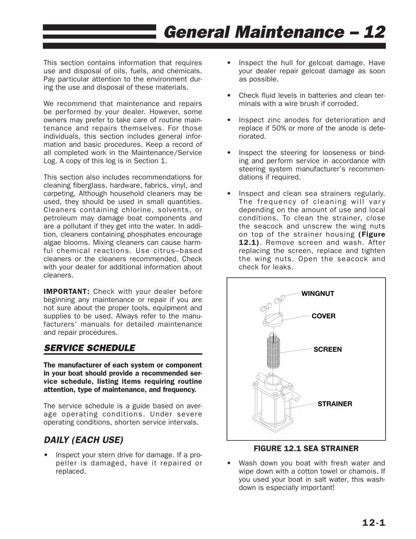
This section contains information that requiresuse and disposal of oils, fuels, and chemicals.Pay particular attention to the environment dur-ing the use and disposal of these materials.
We recommend that maintenance and repairsbe per formed by your dealer. However, someowners may prefer to take care of routine main-tenance and repairs themselves. For thoseindividuals, this section includes general infor-mation and basic procedures. Keep a record ofall completed work in the Maintenance/ServiceLog. A copy of this log is in Section 1.
This section also includes recommendations forcleaning fiberglass, hardware, fabrics, vinyl, andcarpeting. Although household cleaners may beused, they should be used in small quantities.Cleaners containing chlorine, solvents, orpetroleum may damage boat components andare a pollutant if they get into the water. In addi-tion, cleaners containing phosphates encouragealgae blooms. Mixing cleaners can cause harm-ful chemical reactions. Use citrus–basedcleaners or the cleaners recommended. Checkwith your dealer for additional information aboutcleaners.
IMPORTANT: Check with your dealer beforebeginning any maintenance or repair if you arenot sure about the proper tools, equipment andsupplies to be used. Always refer to the manu-facturers’ manuals for detailed maintenanceand repair procedures.
SERVICE SCHEDULE
The manufacturer of each system or componentin your boat should provide a recommended ser-vice schedule, listing items requiring routineattention, type of maintenance, and frequency.
The service schedule is a guide based on aver-age operating condit ions. Under severeoperating conditions, shorten service intervals.
DAILY (EACH USE)• Inspect your stern drive for damage. If a pro-
peller is damaged, have it repaired orreplaced.
• Inspect the hull for gelcoat damage. Haveyour dealer repair gelcoat damage as soonas possible.
• Check fluid levels in batteries and clean ter-minals with a wire brush if corroded.
• Inspect zinc anodes for deterioration andreplace if 50% or more of the anode is dete-riorated.
• Inspect the steering for looseness or bind-ing and perform service in accordance withsteering system manufacturer’s recommen-dations if required.
• Inspect and clean sea strainers regularly.The f requency of c lean ing wi l l var ydepending on the amount of use and localconditions. To clean the strainer, closethe seacock and unscrew the wing nutson top of the strainer housing (Figure12.1). Remove screen and wash. Afterreplacing the screen, replace and tightenthe wing nuts. Open the seacock andcheck for leaks.
• Wash down you boat with fresh water andwipe down with a cotton towel or chamois. Ifyou used your boat in salt water, this wash-down is especially important!
12-1
General Maintenance – 12
STRAINER
SCREEN
COVER
WINGNUT
FIGURE 12.1 SEA STRAINER
• Flush engine (sterndrives) with fresh waterto clean out sand and salt. Make sure bowis higher than engine to prevent water frombacking up into engine. See your dealer forattachments that allow flushing engine witha garden hose.
While flushing, run engine approximately 10-15 minutes. Observe engine multi-functiongauge to make sure engine does not over-heat. Be sure that flushing hose remainsattached to outdrive.
• While cleaning engine compartment, inspectall belts and hoses for deterioration. Makesure clamps are tight.
EVERY 100 HOURS OF OPERATIONOR SEMIANNUALLY• Inspect the engine and stern drive mounting
hardware for tightness.
• Clean the engine flame arrester and ventila-tion hoses.
• Clean and polish the hull bottom using amarine recommended cleaner and wax.
• Inspect the bilge pumps and float switches.Float switches gradually lose sensitivity dueto an accumulation of bilge oil on the oper-ating sur faces. Remove and clean orreplace the float switches periodically.
• Clean and inspect the entire bilge. Dir t inthe bilge will accumulate, soak up oil andeventually become a fire hazard, so keepyour bilge clean. See your dealer for environ-mentally safe bilge cleaners.
• Visually inspect all electrical connections forchafing and corrosion and tighten connec-tions if they are loose.
• Carefully inspect all lifesaving equipment(PFDs) for cut or torn fabric and other signsof deterioration and replace if necessary.
• Carefully check hull for cracks and contactyour dealer if you suspect damage hasoccurred.
• Check the entire fuel system for any evi-dence of line deterioration or fuel leaks. Ifany suspicious lines or connections are dis-covered, have them repaired or replacedbefore going out on the water.
ANNUAL MAINTENANCE• Have a qualified technician thoroughly
inspect your entire electrical system, includ-ing performing a leakage test of each circuit.
ENGINE EXHAUST SYSTEM The exhaust system collects engine combustiongases and exhausts them through fittings at thestern. The hydrocarbons in engine exhaust arepollutants. A well–tuned engine operating at itsbest engine reduces air and water pollution byexhausting fewer hydrocarbons.
Visually inspect the engine and generatorexhaust systems (hoses, joints, manifolds, etc.)for leaks. Make sure all clamps are tight. Checkhoses and exhaust boxes for damage. Replaceany damaged exhaust system component.
Do not remove or bypass mufflers. Local regula-tions may establish maximum noise limits.
Note: Any discoloration around a joint or gasketusually indicates a leak.
SALTWATER CORROSION
The entire boat should be rinsed with freshwater immediately after a cruise in salt water. Ifthe boat is used primarily in salt water, wax thehull monthly and apply corrosion inhibitor to allhardware. See your dealer for products suitablefor the marine salt water environment. Freshwater internal flushing is recommended whenused in salt, polluted or brackish waters. Rec-ommended products include Meguiar’s OneStep Cleaner/Wax.
BOTTOM MAINTENANCE
IMPORTANT: If your boat will be in water contin-uously, we recommend sealing the bottom ofthe hull with a high quality barrier coating.Unsealed gelcoat may form water blisters.Repair of water blister damage is not coveredunder the warranty. If required, contact yourdealer for further information.
12-2
Exhaust gases contain carbon monox-ide. Carbon monoxide is poisonousand can cause unconsciousness ordeath. Shut down engines immediatelyif any exhaust leaks are detected.
WARNING!
The best way to prevent blistering is to minimizethe amount of time the boat remains in the water.If the boat must remain in the water, the applica-tion of a “blister guard” system to the hull belowthe waterline will lessen the possibility of blister-ing. The application of blister guard will decreasethe maximum speed of your boat. Proper applica-tion is essential; contact your dealer or marineservice center for additional information.
We recommend your boat be removed from salt-water and rinsed after each use to preventunwanted marine growth on the hull and tomaintain ultimate high per formance. The bot-tom of your boat must be kept clean! Anybuildup of marine life from water will create dragand af fect the boat’s per formance and ef fi-ciency. Never use brushes or scouring pads onthe bottom of your boat, as this can causesmall scratches that will actually trap in dirt.
Antifouling bottom paint is designed to dissolveslowly to prevent marine growth. Therefore, thehull bottom should be repainted at the beginningof the boating season. Factors to take into con-sideration when selecting a protective bottompaint are water temperature, pollution, salinity,current and organic material in the water.
IMPORTANT: Consult with your dealer for rec-ommended bottom paints and local laws thatgovern your area. Many states regulate thechemical content of bottom paints to meet envi-ronmental standards and regulations. Contactyour dealer for information.
1. Scrub hull bottom with a bristled brush andmixture of soap and water.
NOTE: Repainting the hull bottom is notrequired after each scrubbing unless bare areasare visible in the bottom paint.
2. Sand entire bottom surface of boat.
3. Smooth out all rough areas as required.
4. Clean bottom sur face to remove all dustand foreign materials.
5. Make sure bottom sur face is completelydry.
6. Apply new coat of bottom paint.
NOTE: Always follow manufacturer’s proceduresand recommendations concerning application ofpaint and drying time before putting your boat inthe water.
PROTECTION AGAINST ELECTROLYSIS
IMPORTANT: It is the boat owner’s responsibilityto periodically inspect and replace the sacrificialzinc anodes. Damage resulting from electrolyticcorrosion is not covered by the warranty.
Sacrificial zinc anodes, installed by the dealeror the engine manufacturer, protect the hard-ware that is exposed to the water. Electrolysisattacks the softest or least noble metals first.Because zinc is a less noble metal, it willdecompose before the more noble metals.Check these zinc anodes periodically and havethem replaced as required. See your dealer forparts and service.
Zinc is also used to protect metal that isexposed to saltwater. The salt causes a gal-vanic action that decomposes metals.
DECK AND HULL CARE
IMPORTANT: Keep fiberglass sur faces cleanto prevent dir t from scratching and dulling thefinish. Wash down with a mild soap (dishdetergent or car wash soap) and plenty ofclear water, especially if your boat has beenexposed to salt water.
The finish on your boat is made of highlydurable marine gelcoat. With proper care, thisfinish will last for many years, retaining its lus-trous appearance. For added protection you canhave the hull of your boat coated with anantifouling paint. See your dealer for fur therinformation.
Routine, periodic cleaning is the only practicalway to keep the sur face of your boat lookingshiny and new. Keeping your boat in showroomcondition means greater personal satisfactionand higher resale value. Special cleaning prod-ucts are available from your dealer to removemildew. Boats left outdoors will gradually deteri-orate from exposure to sunlight, water, dust andchemicals in the air. Outdoor exposure may
12-3
Waxed gelcoat surfaces can be veryslippery. Do not wax normally usedportions of the floor deck or gunwales.Do not wax any textured or non-skidsurfaces such as floors, walkways,steps or ladders.
CAUTION!
cause your boat’s surface to show a variety ofchanges, including:
• Chalking (fine, powdery whiteness on thesurface)
• Fading (gradual loss of color)• Yellowing• Loss of gloss
Darker colors tend to exhibit these changesmore rapidly than light colors because theyabsorb more of the sun’s rays (ultraviolet andinfrared).
NOTE: Before using a particular cleaning solu-tion or method for cleaning, it is a good ideato test the material to be cleaned in a hiddenor inconspicuous area for possible adversereactions.
The deck and hull can be easily cleaned withMeguiar's Marine Boat Gel Wash and water(with the exception of oil or heavy grime). Use aclean cloth or sponge. Dir t, sand, or grit in adirty rag could scratch the gelcoat surface. DONOT USE abrasives to clean your boat.
Boat sur faces, even textured walkways andsteps, can be very slippery when covered withsoap suds. Use caution to protect yourself andothers from slips and falls. Wear deck shoes orboat shoes whenever you are in your boat.
After you have thoroughly cleaned your boat,you are ready for a wax application to bring backthe original sheen of your hull. If the deck orhull has oxidized (appearing as a light whitemilky film), you may want to use Meguiar’sHeavy Duty Oxidation Remover or Mirror GlazeColor Restorer before waxing. It is a good ideato wax your boat at least twice a year. In south-ern climates, waxing more frequently may benecessary to protect the boat from the sun’srays.
NOTE: Do not use a spray wax. Wax accidentallysprayed on nonskid sur faces will make themvery slippery.
If nonskid or textured surfaces on decks, walk-ways, and steps become stained, clean themwith a bristle brush and a bathroom fiberglasscleaner. Be careful! Scrubbing smooth gelcoatsurfaces with a bristle brush may scratch thegelcoat.
Keeping both the interior and exterior of yourboat in good condition and inspecting your boatregularly to keep minor problems from becomingmajor ones are good rules of thumb for properboat care. REMEMBER, A BOAT KEPT IN NEARLYNEW CONDITION, REGARDLESS OF AGE,RETAINS A HIGH RESALE VALUE.
FIBERGLASS REPAIR
Although your deck and hull have been designedto withstand normal use, it is inevitable thatsurfaces will become scratched or chipped overa period of time. Superficial scratches can usu-ally be rubbed out with Meguiar's Heavy DutyOxidation Remover.
“Hairline cracks” or “spider webbing” maydevelop in the gelcoat surface of a hull or deck.This can be caused by weathering, impact orother factors. Small blisters or gouges may alsooccur through normal wear. These do not affectthe strength of the hull or deck and can easilybe repaired by you or your dealer.
The affected area should be chipped or sandedaway and a thin layer of color-matched gelcoatapplied. This layer is then sanded smooth andbuffed back to its original luster. Your dealercan obtain color-matched gelcoat and providefurther instructions from the manufacturer.
Fiberglass hulls are tough, but like hulls of anyother materials, they can be damaged. A fiber-glass hull has vir tually no internal stresses.Thus, when a part is broken or punctured, therest of the hull retains its shape. A severe blowwill either be absorbed or result in a definite,localized break. In the case of a break of thisnature, the boat should be returned to yourdealer for repair.
You will need the following items for minorrepairs:
• Gelcoat• DDM (clear liquid catalyst)• Putty knife or equivalent• Razor blade• Fine sandpaper (400 to 600 grade)• Wax paper (piece big enough to cover repair)
12-4
Wire brushes, scouring pads or otherabrasive type materials/solutionsshould never be used on the deck orhull of your boat. They create smallscratch marks that will collect marinegrowth and other foreign materials.
CAUTION!
For minor repairs follow this procedure:
1. Clean the area to be repaired and clear it ofwax and oil.
2. Thoroughly clean out nicks, chips andscratches.
3. Sand area to be repaired so gelcoat willbond.
4. IN A SEPARATE CONTAINER, MEASURE ONLYTHE AMOUNT OF GELCOAT YOU NEED. Mix a2% ratio of catalyst to the amount of gelcoatbeing used (a spoonful of gelcoat willrequire only a drop or two of catalyst).
NOTE: DO NOT pour any unused portions of thegelcoat/catalyst mixture back into either originalcontainer.
5. Apply gelcoat to area leaving a slight liftabove the surface.
6. Cover with wax paper (lack of oxygen helpsmixture set) and let set 20 to 30 minutes.
7. Remove wax paper and shave off excessgelcoat with a razor blade.
8. By the time the area is shaved smooth, youare ready to sand (Use 400 to 600 gradesandpaper, NO SUBSTITUTES.)
9. Rub or buff the fiberglass with FiberglassCleaner/Compound, then polish, then wax.
Some discoloration may occur if your boat hasweathered. For your first attempt at repair,experiment on an area not normally visible. Witha little experience, even the novice can repair ascratch with few, if any, visible repair marks.
HARDWARE AND FITTINGS
Chrome, stainless steel and aluminum hard-ware should be cleaned with Meguiar’s AllMetal Cleaner, followed with an applicationof Meguiar’s All Purpose Metal Polish.
AVOID THE USE OF DETERGENTS OR ABRA-SIVES WHEN CLEANING HARDWARE.
Inspect all hardware and fittings to make surethey are secure. All screws, bolts, clamps,cleats, etc., must be tight.
UPHOLSTERY
Your boat’s seats and vinyl upholstery shouldbe kept as clean as the exterior finish to pro-long life and beauty.
SEAT COVERINGS & VINYLThe seat coverings and vinyl trim are made oftemperature resistant vinyl.
1. Always try to clean up spills quickly to pre-vent staining.
2. Clean dirt and smudges with Meguiar's Vinyl& Rubber Cleaner/Conditioner. If necessary,scrub with a soft bristle brush to removedirt from textured vinyl. Dry with a soft, lint-free cloth or towel.
3. Use a stronger detergent such as Meguiar’sHeavy Duty Vinyl Cleaner for tough stains. Fol-low the instructions on the bottle label forground-in dirt, a nylon brush can be used toscrub out stains.
Cer tain household cleaners, powdered abra-sives, steel wool and industrial cleaners cancause damage and discoloration and are notrecommended. Petroleum-based cleaning prod-ucts such as dry cleaning fluids and lacquersolvents should not be used, as they willremove the printed pattern and gloss. Waxesshould be used with caution. Many contain dyesor solvents that can permanently damage theprotective coating.
4. Suntan oil will damage vinyl upholstery. Usesuntan lotion instead of suntan oil.
5. Removable outside seat cushions should beplaced inside when not in use.
Exposure to the sun is the enemy of all uphol-ster y materials. For maximum life, werecommend keeping them covered with a cock-pit or full length cover when you are not usingyour boat.
12-5
Gelcoat and fiberglass resin areflammable; work in well-ventilatedarea free from any fire hazard.
WARNING!
INTERIOR FABRICS
Treat the fabric upholstery the same as homefabric upholster y. Vacuum and shampoo tomaintain upholstery and to keep it clean andodor free. Spray with Lysol™ or other disinfec-tant to prevent the build up of mildew.
WINDSHIELDS AND WINDOWS
Safety glass windows and windshields may becleaned just like those in a car. Plastic and Plex-iglass surfaces require special attention. Floodacr ylic windshields and por t windows withplenty of clean warm water. Use a soft cleancloth. Rinse with clear water.
Vibration may loosen windshield fasteners andbraces during normal use. These should bechecked periodically for tightness.
CARPETING
EXTERIORScrub indoor/outdoor carpeting with a brushusing mild detergent and warm water, then thor-oughly rinse with clear water. Allow carpet to drycompletely before use. Apply a light coating ofScotch Guard to protect against accidentalspills.
INTERIORVacuuming and occasional carpet shampoo arerecommended for extended life and appear-ance. Apply a light coating of Scotch Guard toprotect against accidental spills.
CANVAS
Canvas or “bimini tops” are designed to protectthe helm seating areas from the sun. Althoughthese tops are intended to provide ample weatherprotection for the helm, they are not completelyweather tight like a winter storage cover.
To keep exterior seat cushion foam from gettingwet, we recommend that the cushions beremoved and properly stored when not in useunless the boat is fitted with a full length cover.
CLEANINGIMPORTANT: Do not use hot water, dry in anautomatic dryer, dry clean or steam press canvas.
1. Wet down all canvas. Use a soft bristlebrush and scrub with a mild detergent andwater solution.
2. Use a mild solution of ammonia/water andscrub for heavy soil or mildew build up. Besure to rinse thoroughly.
3. Brush or sweep underside of the top. Spraywith Lysol™ or other disinfectant to preventmildew.
CARE1. Care for vinyl-coated canvas as you would
vinyl upholstery.
2. Lubricate zippers with paraffin and snapswith petroleum jelly.
3. If a leak occurs along a canvas seam, rubwith paraf fin or apply a light coating ofScotch Guard®.
4. Air dry all canvas material before storing.Never store canvas while damp or wet andprovide proper ventilation to prevent mildew.
5. Avoid mooring under trees.
6. Never tow your boat with the top up.
7. When not in use, remove the top and storein the boot on board your boat.
12-6
Do not use window cleaning sprays,scouring compounds or solvents toclean plastic windows. Scouring com-pounds will scratch the windows.Sprays and solvents penetrate the sur-faces and cause hazing which willobstruct visibility.
CAUTION!
AbaftToward the stern.
AbeamAmidships, at a right angle to the keel.
AboardOn, in, or into a boat.
ABYCAmerican Boat and Yacht Council, Inc., theorganization that sets voluntary safety andconstruction standards for small craft in theUSA.
AdriftWithout motive power and without anchor ormooring.
AfloatOn the water.
AftDescribing the after section of a vessel, orthings to the rear of amidships and near thestern.
AgroundTouching bottom.
AmidshipsIn the center, the center portion of a vessel.
AnchorA forging or casting shaped to grip the seabottom and, by means of a cable or rope,hold a boat in a desired position.
AnchorageA customary, suitable and (usually) desig-nated harbor area in which vessels mayanchor.
AsternToward the stern. An object that is aft of aboat is said to be astern of the boat.
AthwartAcross.
AweighOff the bottom, said of an anchor.
AyeYes, while aboard a boat or ship. Means “Iunderstand.”
Bail (Bale)To remove water from a boat by pump orbailer.
BallastHeavy material such as iron, lead, or stoneplaced in the bottom of the vessel.
BeaconA post or buoy placed over a shoal or bankto warn vessels, also a signal mark on land.
BeamImaginary line amidships at right angles tokeel of vessel. Also vessel’s width amid-ships.
BearingThe direction or point of the compass inwhich an object is seen.
BelayTo make fast to a cleat or belaying pin; tocancel an order.
BelowBeneath, or under, the deck. One goesbelow when going down into the cabin.
BendTo fasten by means of a bend or knot.
BerthA position, as a place to sleep or in which avessel maybe made fast; a margin of safety,as “a wide berth.”
BilgeThe lower internal part of a boat’s hull.
BollardA strong post for holding lines fast.
BowThe forward part or front of the boat.
BreakersWaves cresting as they reach shallow water,as at or on a beach.
14-1
Nautical Glossary – 14
BreakwaterA structure, usually stone or concrete,builtto create a harbor or improve an existingone.
BulkheadVertical partition in a boat.
Burdened VesselFormer term for the vessel which must stayclear of vessels with the right-of-way.
Calking (Caulking)Forcing filler material into the seams of theplanks in a boat’s deck or sides, to makethem watertight.
CamberThe arch of a deck, sloping downward fromthe center toward the sides.
CapsizeTo turn over.
Carburetor Backfire Flame ArrestorRequired equipment on all motorboatsexcept outboards and diesels. Reduceschance of fire caused by backfires in inter-nal combustion engines.
Cardinal PointsThe four main points of a compass; north,east, south, and west.
CeilingThe inside lining of the hull.
CertificateGovernment paper, such as a boat’slicense.
ChartA map of a body of water that contains pilot-ing information.
ChineThe intersection of sides and bottom of aboat.
CleatA piece of wood or metal with projectingends to which lines are made fast.
ClinkerA method of planking in which the loweredge of each strake overlaps the upperedge of the strake next below. (Also calledlapstrake.)
CoamingA raised edge, as around par t or all of acockpit, that prevents seawater from enter-ing the boat.
Coast GuardThe federal marine law enforcement andrescue agency in the US.
CockpitA well or sunken space in the afterdeck of asmall boat for the use of the helmsman andcrew.
CompanionwayA hatch or entrance, from deck to cabin.
CompassThe instrument which shows the heading ofa vessel.
CowlsHooded openings used for ventilation.
CradleA frame used to support a vessel on land.
CurrentThe movement of the water in a horizontaldirection.
DeadriseThe rise of the bottom of a midships framefrom the keel to the bilge.
DeckAny permanent covering over a compar t-ment.
Deep-sixTo discard or throw overboard.
Depth SounderAn electronic depth-finding instrument, mea-suring the time a sound wave takes to gofrom the vessel to the bottom and return,then displaying the result in feet, fathoms,or meters.
DinghyA small, open boat.
Displacement HullType of hull that plows through the watereven when more power is added.
14-2
DockAn enclosed or nearly enclosed water area;all the port installations; a place where ves-sels can moor, as a pier, wharf, or floatingdock.
Documented VesselVessel registered with the U.S. Coast Guard.
DolphinA small group of piles, in the water, gener-ally used for mooring or as a channelmarker.
DraftThe depth of the vessel below the waterline, measured vertically to the lowest partof the hull.
DunnageMats, boughs, pieces of wood, or otherloose materials placed under or amonggoods carried as cargo in the hold of a shipto keep them dry and to prevent theirmotion and chafing; cushioning or paddingused in a shipping container to protect frag-ile articles against shock and breakage;baggage or personal effects.
EbbAn outgoing tide.
EstuaryAn inlet or arm of the sea.
FathomSix feet.
FendersObjects placed along the side of the boat toprotect the hull from damage.
FlareThe outward spread of the boat’s sides fromthe waterline to the rail at the bow. Also, apyrotechnic signalling device that can indi-cate distress.
ForeUsed to distinguish the forward part of aboat or things forward of amidships. It isthe opposite of aft or after.
ForwardToward the bow.
FrameRibs of the hull, extending from the keel tothe highest continuous deck.
FreeboardThe vertical distance measured on a boat’sside from the waterline to the gunwale.
GalleyThe kitchen area of a boat.
GimbalsSwivels used to keep equipment level.
Give-Way VesselThe one which must stay clear of vesselswhich have the right-of-way.
Grab RailA convenient grip, on a cabin top or along acompanion ladder.
Gunwale (pronounced gunnel)The upper edge of a boat’s side.
HarborA safe anchorage, protected from moststorms; may be natural or man-made, withbreakwaters and jetties; a place for dockingand loading.
HatchAn opening in a boat’s deck for persons orcargo to go below.
HeadA marine toilet.
HeadwayForward motion of a vessel through thewater.
HelmThe wheel or t i l ler by which a ship issteered.
Holding TankStorage tank for sewage, so that it will notbe pumped overboard into the water.
HullThe body of a boat.
HypothermiaA physical condition where the body losesheat faster than it can produce it.
InboardMore toward the center of a vessel; inside;a motor fitted inside the boat.
14-3
Inland RulesRules of the road that apply to vessel opera-tion in harbors and certain rivers, lakes, andinland waterways.
Intracoastal WaterwaysICW: bays, rivers and canals along thecoasts (such as Atlantic and Gulf of Mexicocoasts), connected so that vessels maytravel without going into the open sea.
JettyA structure, usually masonry, projecting outfrom the shore; a jetty may protect a harborentrance.
KeelThe permanently positioned, fore-and-aftbackbone member of a boat’s hull.
KnotTo bend a line. Also, a unit of speed equalto one nautical mile (6,076.10 feet) anhour.
Launch(1) To put a vessel into the water;(2) A small open powerboat, mainly used for
transpor tation between a vessel andshore.
LeeThe side opposite to that from which thewind blows.
LeewardSituated on the side turned away from thewind. (Opposite of windward.)
LeewayThe amount a boat is carried sideways bythe wind’s force or current.
Limber HolesDrainage holes in the bilge timbers of a ves-sel, allowing to run to a low point forpumping out.
List(1) A continuous leaning to one side, often
caused by an imbalance in stowage or aleak into one compartment;
(2) A light list is a printed listing of aids tonavigation, in geographical order orinclining of a vessel toward the side.
LOALength over all; the maximum length of avessel’s hull, excluding projecting spars orrudder.
LockerA storage place, a closet.
LogA record or diary of a vessel’s journey.
Lubber’s LineA mark or permanent line on a compassthat shows the course of the boat.
Making WayMaking progress through the water.
MarinaA place, essentially a dock area, wheresmall recreational craft are kept; usuallyfloats or piers, as well as service facilities,are available.
MAYDAYA radio distress call, from the frenchm’aidez (help me); SOS in Morse Code.
MooringCommonly, the anchor chain, buoy, pennant,etc., by which a boat is permanentlyanchored in one location.
MotorA source of mechanical power.
MotorboatAny watercraft 65 feet or less in length pro-pelled by machinery, whether or not suchmachinery is the principal source of propul-sion.
NavigationThe art of conducting a ship from port toport.
Nautical Mile6076.12 feet, or 1852 meters, an interna-tional standard; the geographical mile, thelength of one minute of latitude at the equa-tor, is 6087.20 feet.
Nun BuoyA conical, red buoy bearing an even numberand marking the starboard side of a channelfrom seaward.
14-4
OarA long, wooden instrument with a flat bladeat one end, used for propelling a boat.
Outboard(1) A propulsion unit for boats, attached at
the transom; includes motor, drive-shaft,and propeller; fuel tank and battery maybe integral or installed separately in theboat;
(2) Outside or away from a vessel’s hull;opposite of inboard.
OutdriveA propulsion system for boats, with aninboard motor operating an exterior drive,with driveshaft, gears, and propeller; alsocalled stern-drive and inboard/outboard.
Overall LengthThe extreme length of a vessel, excludingspars or rigging fittings. See LOA.
PainterA rope attached to the bow of a boat formaking it fast.
PFDPersonal Flotation Device.
PierA structure, usually wood or masonr y,extending into the water, used as a landingplace for boats and ships.
PileA vertical wooden or concrete pole, driveninto the bottom; may be a support for a pieror floats; also used for mooring.
PilingA structure of piles.
Pitch(1) The up and down movement as the bow
and stern rise and fall due to waveaction;
(2) The theoretical distance advanced by apropeller in one revolution.
Planing HullType of hull that is shaped to lift out of thewater at high speed and ride on the surface.
PortThe left side of a boat when you are facingthe bow, also a destination or harbor.
Privileged VesselFormer term for the vessel with the right-of-way.
PropellerWheel or screw. Mechanism that pusheswater aft to propel the boat.
RiggingThe general term for all lines(ropes) of avessel.
RollThe sideward motion of a boat caused bywind or waves.
Rules of the RoadThe nautical traffic rules for preventing colli-sions on the water.
ScopeThe length of the anchor rope or chain. 6 to1 scope means that the length of theanchor rope from the boat to the anchor is 6times the depth of the water.
ScupperA hole allowing water to run off the deck.
Sea AnchorA floating canvas cone, held open by wirerings, with an opening in the smaller end,and a rope bridle at the larger end attachedto a line leading to the vessel; used instorm conditions to (a) keep the bow of theboat to the wind, and (b) slow downwinddrift of the boat.
Sea CockA through-hull valve, a shut-off on a plumb-ing or drain pipe between the vessel’sinterior and the sea.
Slip(1) A berth for a boat between two piers or
floats;(2) The percentage difference between the
theoretical and the actual distance thata propeller advances when turning inwater under load.
SoleThe cabin or cockpit floor.
Spar BuoyA channel marker that looks like a tall, slen-der pole.
14-5
Stand-On VesselThe vessel with the right-of-way.
StarboardThe right side of a boat when you are facingthe bow.
SternThe after end or back of the boat.
StowTo store items neatly and securely.
StrakePlanks running fore and aft on the outsideof a vessel.
TaffrailThe rail around a boat’s stern.
TideThe alternate rise and fall of waters causedby the gravitational attraction of moon orsun.
Topsides(1) The sides of a vessel above the water-
line;(2) On deck as opposed to below deck.
TransomThe transverse planking which forms theafterend of a small, square-ended boat.(Outboard motors are usually attached to atransom.)
TrimTo arrange weights in a vessel in such amanner as to obtain desired draft at bowand stern.
TrimaranBoat with three hulls, the center one is thelargest.
UnbendTo cast-off or untie.
UnderwayVessel in motion, i.e., when not moored, atanchor or aground.
USPSUnited States Power Squadron, a privatemembership organization that specializes inboating education and good boating prac-tices.
VesselEvery kind of watercraft, other than a sea-plane on the water, capable of being used as ameans of transportation on water.
VHF RadioA Very High Frequency electronic communi-cations and direction finding system.
WakeMoving waves, created by vessel motion.Track or path that a boat leaves behind it,when moving across the water.
WashThe loose or broken water left behind a ves-sel as it moves along; the surging action ofwaves.
WaterlineThe intersection of a vessel’s hull and thewater’s surface; the line separating the bot-tom paint and the topsides.
WayMovement of a vessel through the water.Technically it is under way when not atanchor, aground, or made fast to the shore.The common usage is interpreted asprogress through the water. Headway whengoing forward and Sternway when it is goingbackwards.
WellArea at the rear of a boat where the motormay be located.
WharfA structure, parallel to the shore, for dock-ing vessels.
Wheel(1) The steering wheel;(2) The propeller.
Whistle SignalA standard communication signal betweenboats, to indicate change of course, danger,or other situations.
WindwardSituated on the side closest to the wind.(Opposite of leeward.)
YawTo swing or steer off course, as when run-ning with a quartering sea.
14-6
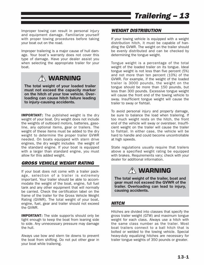
Improper towing can result in personal injuryand equipment damage. Familiarize yourselfwith proper towing procedures before takingyour boat out on the road.
Improper trailering is a major cause of hull dam-age. Your boat’s warranty does not cover thistype of damage. Have your dealer assist youwhen selecting the appropriate trailer for yourboat.
IMPORTANT: The published weight is the dryweight of your boat. Dry weight does not includethe weights of outboard motors, batteries, gaso-line, any optional items, gear or trailers. Theweight of these items must be added to the dryweight to determine the proper trailer GVWRneeded. On boats equipped with stern driveengines, the dry weight includes the weight ofthe standard engine. If your boat is equippedwith a larger than standard engine, you mustallow for this added weight.
GROSS VEHICLE WEIGHT RATING
If your boat does not come with a trailer pack-age, selection of a trai ler is extremelyimportant. Your trailer should be able to accom-modate the weight of the boat, engine, full fueltank and any other equipment that will normallybe carried. Check the certification label on theframe of the trailer for the Gross Vehicle WeightRating (GVWR). The total weight of your boat,engine, fuel, gear and trailer should not exceedthe GVWR.
IMPORTANT: The side supports should only betight enough to keep the boat from leaning sideto side. Any unnecessary pressure may damagethe hull.
Always use bow and stern tie downs to preventthe boat from shifting. Do not put other gear inyour boat while trailering.
WEIGHT DISTRIBUTION
If your towing vehicle is equipped with a weightdistribution hitch, it must be capable of han-dling the GVWR. The weight on the trailer shouldbe evenly distributed and can be checked bydetermining the tongue weight.
Tongue weight is a percentage of the totalweight of the loaded trailer on its tongue. Idealtongue weight is not less than five percent (5%)and not more than ten percent (10%) of theGVWR. For example, if the weight of the loadedtrailer is 3000 pounds, the weight on thetongue should be more than 150 pounds, butless than 300 pounds. Excessive tongue weightwill cause the front end of the towing vehicle tosway. Insufficient tongue weight will cause thetrailer to sway or fishtail.
To avoid personal injury and property damage,be sure to balance the load when trailering. Iftoo much weight rests on the hitch, the frontend of the vehicle will sway or oversteer. Insuffi-cient weight on the trailer will cause the trailerto fishtail. In either case, the vehicle will behard to handle and could become uncontrollableat high speeds.
State regulations usually require that trailersabove a specified weight rating be equippedwith brakes. Requirements vary; check with yourdealer for additional information.
HITCH
Hitches are divided into classes that specify thegross trailer weight (GTW) and maximum tongueweight for each class. Always use a hitch withthe same class number as the trailer. Mostboat trailers connect to a ball hitch that isbolted or welded to the towing vehicle. Specialheavy-duty equalizing hitches are necessary fortrailer tongue weights of 350 pounds or greater.
13-1
Trailering – 13
The total weight of your loaded trailermust not exceed the capacity markeron the hitch of your tow vehicle. Over-loading can cause hitch failure leadingto injury-causing accidents.
WARNING!
The total weight of the trailer, boat andgear must not exceed the GVWR of thetrailer. Overloading can lead to injury,causing accidents.
WARNING!
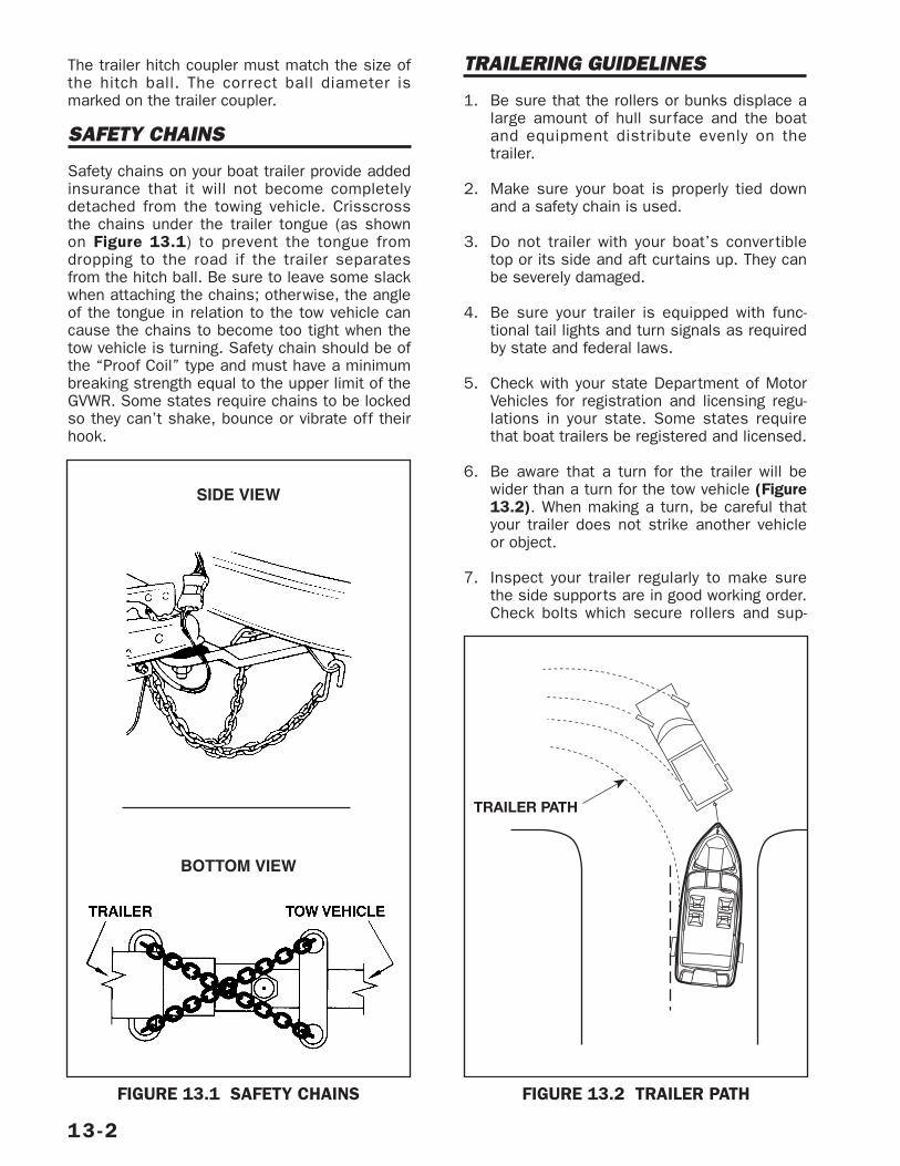
The trailer hitch coupler must match the size ofthe hitch ball. The correct ball diameter ismarked on the trailer coupler.
SAFETY CHAINS
Safety chains on your boat trailer provide addedinsurance that it will not become completelydetached from the towing vehicle. Crisscrossthe chains under the trailer tongue (as shownon Figure 13.1) to prevent the tongue fromdropping to the road if the trailer separatesfrom the hitch ball. Be sure to leave some slackwhen attaching the chains; otherwise, the angleof the tongue in relation to the tow vehicle cancause the chains to become too tight when thetow vehicle is turning. Safety chain should be ofthe “Proof Coil” type and must have a minimumbreaking strength equal to the upper limit of theGVWR. Some states require chains to be lockedso they can’t shake, bounce or vibrate off theirhook.
TRAILERING GUIDELINES
1. Be sure that the rollers or bunks displace alarge amount of hull surface and the boatand equipment distribute evenly on thetrailer.
2. Make sure your boat is properly tied downand a safety chain is used.
3. Do not trailer with your boat’s convertibletop or its side and aft curtains up. They canbe severely damaged.
4. Be sure your trailer is equipped with func-tional tail lights and turn signals as requiredby state and federal laws.
5. Check with your state Department of MotorVehicles for registration and licensing regu-lations in your state. Some states requirethat boat trailers be registered and licensed.
6. Be aware that a turn for the trailer will bewider than a turn for the tow vehicle (Figure13.2). When making a turn, be careful thatyour trailer does not strike another vehicleor object.
7. Inspect your trailer regularly to make surethe side supports are in good working order.Check bolts which secure rollers and sup-
13-2
FIGURE 13.1 SAFETY CHAINS
TRAILER PATH
FIGURE 13.2 TRAILER PATH
BOTTOM VIEW
SIDE VIEW
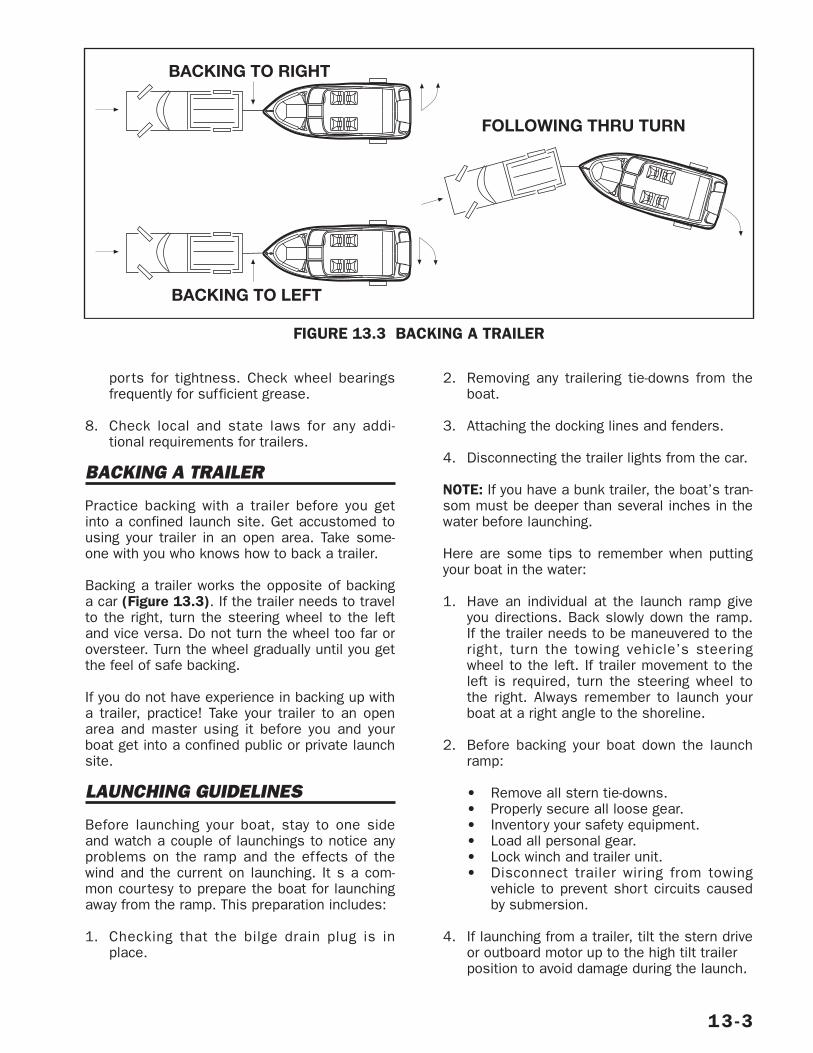
ports for tightness. Check wheel bearingsfrequently for sufficient grease.
8. Check local and state laws for any addi-tional requirements for trailers.
BACKING A TRAILER
Practice backing with a trailer before you getinto a confined launch site. Get accustomed tousing your trailer in an open area. Take some-one with you who knows how to back a trailer.
Backing a trailer works the opposite of backinga car (Figure 13.3). If the trailer needs to travelto the right, turn the steering wheel to the leftand vice versa. Do not turn the wheel too far oroversteer. Turn the wheel gradually until you getthe feel of safe backing.
If you do not have experience in backing up witha trailer, practice! Take your trailer to an openarea and master using it before you and yourboat get into a confined public or private launchsite.
LAUNCHING GUIDELINES
Before launching your boat, stay to one sideand watch a couple of launchings to notice anyproblems on the ramp and the effects of thewind and the current on launching. It s a com-mon courtesy to prepare the boat for launchingaway from the ramp. This preparation includes:
1. Checking that the bilge drain plug is inplace.
2. Removing any trailering tie-downs from theboat.
3. Attaching the docking lines and fenders.
4. Disconnecting the trailer lights from the car.
NOTE: If you have a bunk trailer, the boat’s tran-som must be deeper than several inches in thewater before launching.
Here are some tips to remember when puttingyour boat in the water:
1. Have an individual at the launch ramp giveyou directions. Back slowly down the ramp.If the trailer needs to be maneuvered to theright, turn the towing vehicle’s steeringwheel to the left. If trailer movement to theleft is required, turn the steering wheel tothe right. Always remember to launch yourboat at a right angle to the shoreline.
2. Before backing your boat down the launchramp:
• Remove all stern tie-downs.• Properly secure all loose gear.• Inventory your safety equipment.• Load all personal gear.• Lock winch and trailer unit.• Disconnect trailer wiring from towing
vehicle to prevent short circuits causedby submersion.
4. If launching from a trailer, tilt the stern driveor outboard motor up to the high tilt trailer position to avoid damage during the launch.
13-3
BACKING TO RIGHT
BACKING TO LEFT
FOLLOWING THRU TURN
FIGURE 13.3 BACKING A TRAILER
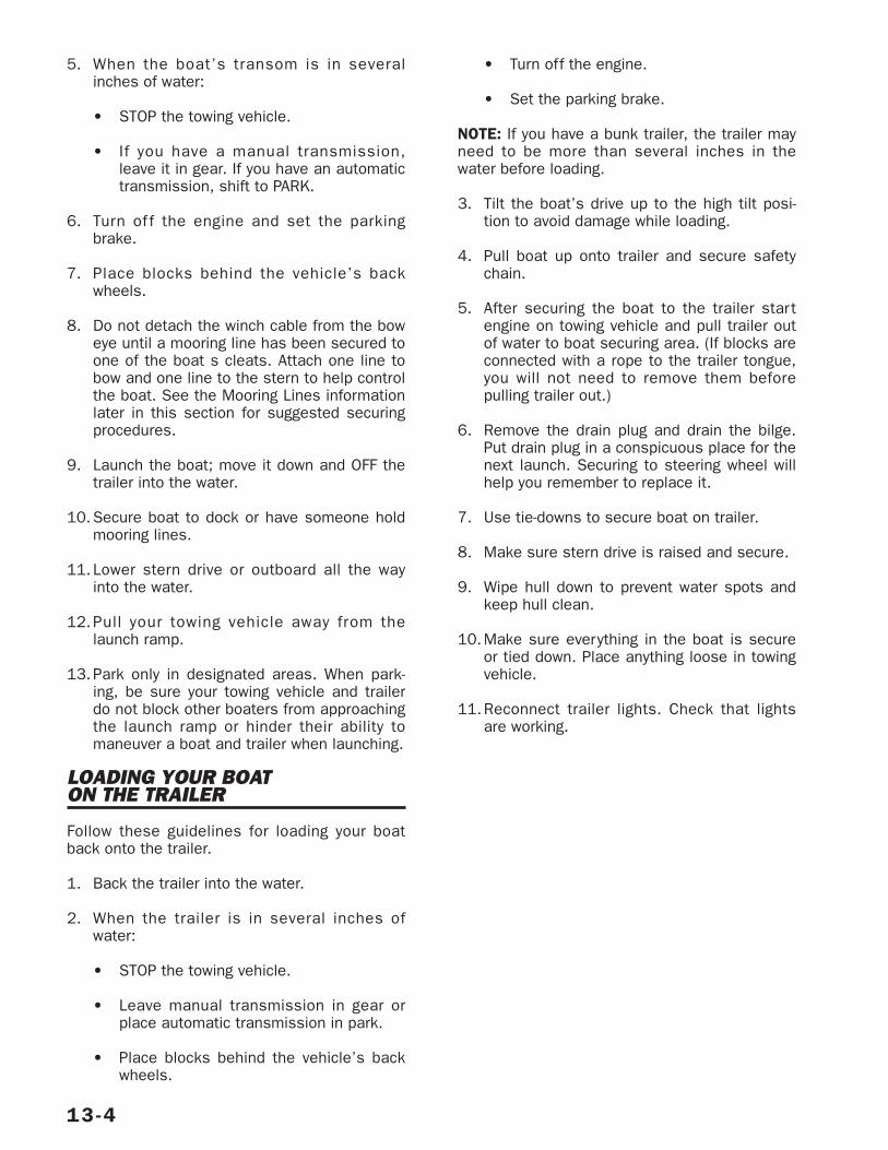
5. When the boat’s transom is in severalinches of water:
• STOP the towing vehicle.
• If you have a manual transmission,leave it in gear. If you have an automatictransmission, shift to PARK.
6. Turn of f the engine and set the parkingbrake.
7. Place blocks behind the vehicle’s backwheels.
8. Do not detach the winch cable from the boweye until a mooring line has been secured toone of the boat s cleats. Attach one line tobow and one line to the stern to help controlthe boat. See the Mooring Lines informationlater in this section for suggested securingprocedures.
9. Launch the boat; move it down and OFF thetrailer into the water.
10.Secure boat to dock or have someone holdmooring lines.
11.Lower stern drive or outboard all the wayinto the water.
12.Pull your towing vehicle away from thelaunch ramp.
13.Park only in designated areas. When park-ing, be sure your towing vehicle and trailerdo not block other boaters from approachingthe launch ramp or hinder their ability tomaneuver a boat and trailer when launching.
LOADING YOUR BOAT ON THE TRAILER
Follow these guidelines for loading your boatback onto the trailer.
1. Back the trailer into the water.
2. When the trailer is in several inches ofwater:
• STOP the towing vehicle.
• Leave manual transmission in gear orplace automatic transmission in park.
• Place blocks behind the vehicle’s backwheels.
• Turn off the engine.
• Set the parking brake.
NOTE: If you have a bunk trailer, the trailer mayneed to be more than several inches in thewater before loading.
3. Tilt the boat’s drive up to the high tilt posi-tion to avoid damage while loading.
4. Pull boat up onto trailer and secure safetychain.
5. After securing the boat to the trailer startengine on towing vehicle and pull trailer outof water to boat securing area. (If blocks areconnected with a rope to the trailer tongue,you will not need to remove them beforepulling trailer out.)
6. Remove the drain plug and drain the bilge.Put drain plug in a conspicuous place for thenext launch. Securing to steering wheel willhelp you remember to replace it.
7. Use tie-downs to secure boat on trailer.
8. Make sure stern drive is raised and secure.
9. Wipe hull down to prevent water spots andkeep hull clean.
10.Make sure everything in the boat is secureor tied down. Place anything loose in towingvehicle.
11.Reconnect trailer lights. Check that lightsare working.
13-4


![Quickrecognitionguide Vol1 Cruisers[1]](https://img.pdfslide.us/doc/110x75/552b4d7655034688478b466f/quickrecognitionguide-vol1-cruisers1.jpg)