Embed Size (px)
Citation preview

4/12/2011
1
Evaluation of the Orientation of 90° and 180° Reinforcing Bar Hooks in Wide
Members
By:
Nichole Podhorsky, M.S. Student
Lesley Sneed, Ph.D., P.E., Missouri S&T
Outline
I. IntroductionII. ObjectiveIII. Experimental Program1. Test Setup2. Beam‐end Specimens3. Instrumentation
IV. Test Specimen ConstructionV. ProcedureVI. Material PropertiesVII. Preliminary Results
Introduction
Bond of Reinforced Concrete is influenced by:
Bond is influenced by:• Steel properties• Concrete properties• Structural characteristics
Bond Transfer forces:• Friction forces• Chemical adhesion• Mechanical anchorage
Minor, John, and James O. Jirsa. "Behavior of Bent Bar Anchorages." ACI Journal 1975
l
Introduction
Bond transfer forces: Deformed (ribbed) bar
ACI Committee 408. “Bond and Development of Straight Reinforcing Bars in Tension." American Concrete Institute (2003)
Introduction
Hooked Bar in Concrete:
Park, Robert, and Thomas Paulay. Reinforced Concrete Structures. New York, NY: J. Wiley and Sons, 1975.
Introduction
Evaluation of 90° and 180° bar hooks• Transverse reinforcement• Hook is usually in the vertical direction
Construction site photos(heavily reinforced shallow member)

4/12/2011
2
Objective
Evaluation of 90° and 180° bar hooks• Evaluate the limits of hook tilt• If possible, recommend limitations of hook tilt
Schematic of a hooked bar in a concrete slab
Experimental Program
Test Setup:• Pullout test (a)• Beam‐end test (b)• Beam anchorage test (c)g ( )
ACI Committee 408. “Bond and Development of Straight Reinforcing Bars in Tension." American Concrete Institute (2003)
Experimental Program
Beam‐end Test:
Minor and Jirsa beam‐end specimen Ehsani et al beam‐end specimen
Experimental Program
Beam‐end Test ‐ Reactions
Experimental Program
Beam‐end Specimen Design:Modified for compression strut
Compression strut from ACI 318‐08Modified beam‐end specimen
Experimental Program
Beam‐end Specimen Design:
Height• Concrete cover over tail extension, 3”• Tail length of the bar per ACI• Diameter of the bar, db• Cover over bar, 3db
Length• Height• 4” out of compression strut• Diameter of the bar, db• Concrete cover, 3”
4/12/2011
3
Experimental Program
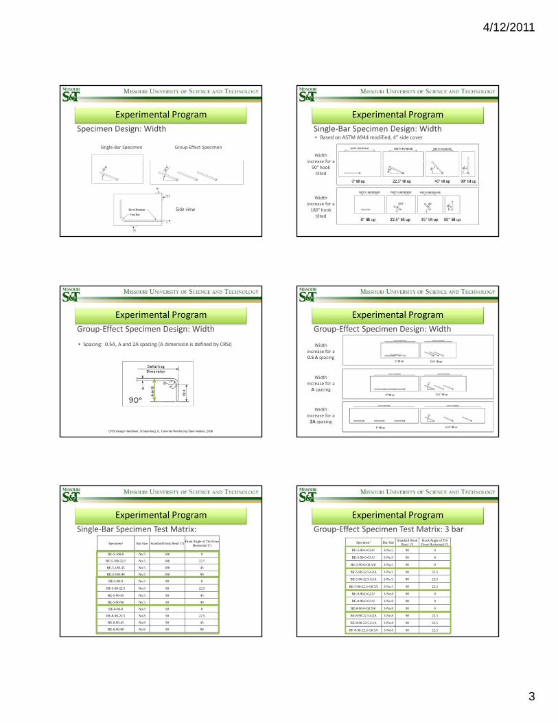
Specimen Design: Width
Single‐Bar Specimen Group‐Effect Specimen
Side view
Experimental Program
Single‐Bar Specimen Design: Width• Based on ASTM A944 modified, 4” side cover
Width increase for aincrease for a 90° hook tilted
Width increase for a 180° hook tilted
Experimental Program
Group‐Effect Specimen Design: Width
• Spacing: 0.5A, A and 2A spacing (A dimension is defined by CRSI)
CRSI Design Handbook. Schaumburg, IL: Concrete Reinforcing Steel Institute, 2008
Experimental Program
Group‐Effect Specimen Design: Width
Width increase for a 0.5 A spacing
Width increase for a A spacing
Width increase for a 2A spacing
Experimental Program
Specimen1 Bar Size Standard Hook Bend (º)Hook Angle of Tilt From
Horizontal (º)
BE-5-180-0 No.5 180 0
BE-5-180-22 5 No 5 180 22 5
Single‐Bar Specimen Test Matrix:
BE 5 180 22.5 No.5 180 22.5
BE-5-180-45 No.5 180 45
BE-5-180-90 No.5 180 90
BE-5-90-0 No.5 90 0
BE-5-90-22.5 No.5 90 22.5
BE-5-90-45 No.5 90 45
BE-5-90-90 No.5 90 90
BE-8-90-0 No.8 90 0
BE-8-90-22.5 No.8 90 22.5
BE-8-90-45 No.8 90 45
BE-8-90-90 No.8 90 90
Experimental Program
Group‐Effect Specimen Test Matrix: 3 bar
Specimen1 Bar SizeStandard Hook
Bend (º)Hook Angle of Tilt From Horizontal (º)
BE-5-90-0-G2A2 3-No.5 90 0
BE-5-90-0-G1A2 3-No.5 90 0
BE-5-90-0-G0.5A2 3-No.5 90 0
BE-5-90-22.5-G2A 3-No.5 90 22.5
BE-5-90-22.5-G1A 3-No.5 90 22.5
BE-5-90-22.5-G0.5A 3-No.5 90 22.5
BE-8-90-0-G2A2 3-No.8 90 0
BE-8-90-0-G1A2 3-No.8 90 0
BE-8-90-0-G0.5A2 3-No.8 90 0
BE-8-90-22.5-G2A 3-No.8 90 22.5
BE-8-90-22.5-G1A 3-No.8 90 22.5
BE-8-90-22.5-G0.5A 3-No.8 90 22.5
4/12/2011
4
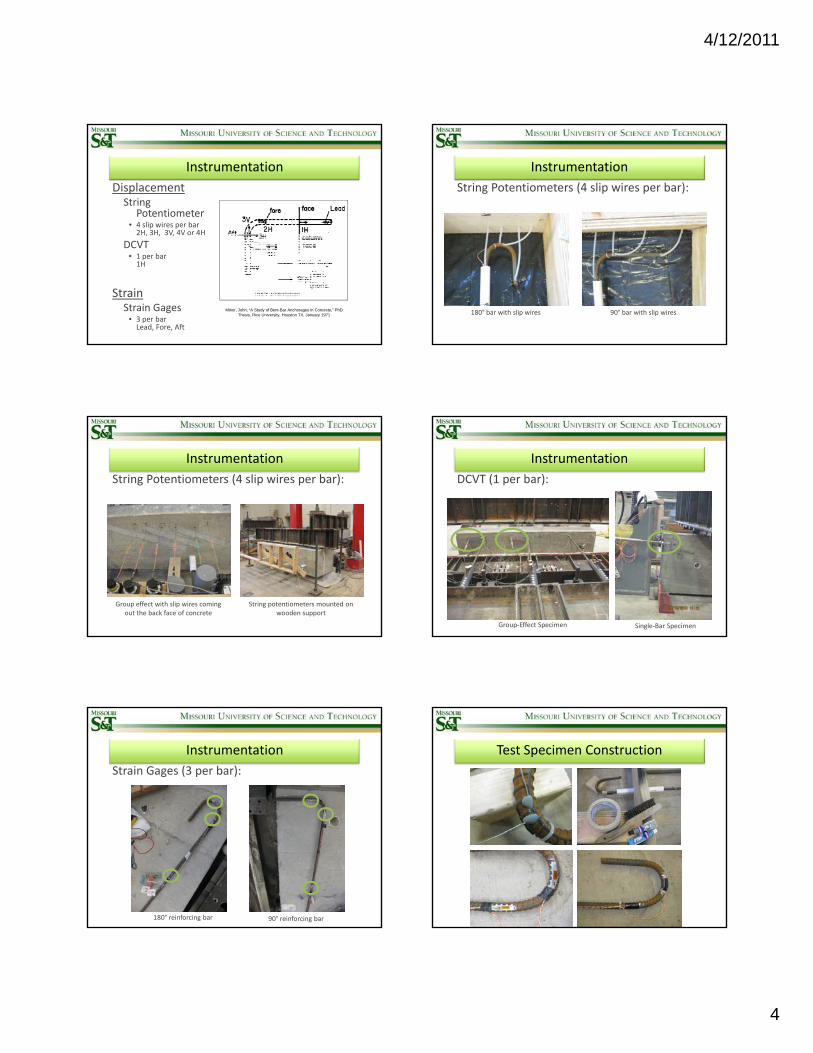
Instrumentation
DisplacementString
Potentiometer• 4 slip wires per bar 2H, 3H, 3V, 4V or 4H2H, 3H, 3V, 4V or 4H
DCVT • 1 per bar 1H
StrainStrain Gages
• 3 per bar Lead, Fore, Aft
Minor, John, “A Study of Bent-Bar Anchorages in Concrete,” PhD Thesis, Rice University, Houston TX, January 1971
Instrumentation
String Potentiometers (4 slip wires per bar):
90° bar with slip wires180° bar with slip wires
Instrumentation
String Potentiometers (4 slip wires per bar):
String potentiometers mounted on wooden support
Group effect with slip wires coming out the back face of concrete
Instrumentation
DCVT (1 per bar):
Single‐Bar SpecimenGroup‐Effect Specimen
Instrumentation
Strain Gages (3 per bar):
180° reinforcing bar 90° reinforcing bar
Test Specimen Construction

4/12/2011
5
Test Specimen Construction Test Specimen Construction
Procedure
Test Setup:
Single‐Bar Specimen
Procedure
Single‐Bar Specimen Test Setup:
Elevation of test setup Anchorage system, loading cell, and hydraulic jack
Procedure
Group‐Effect Specimen Test Setup:
Elevation of test setup Anchorage system, loading cell, and hydraulic jack
Procedure
Testing Procedure:Monotonic Loading every 2 minutes • Allows stabilization of condition• Allows for recording of data
No. 5 Bar:• Loaded in 500 lb increments • (36 load stages before yield of 60ksi bar)
No. 8 Bar:• Loaded in 1300 lb increments • 36 load stages before yield of 60ksi bar)

4/12/2011
6
Procedure
Loading Specimen:
3 Hydraulic Jack Setup
Hand Pump
Procedure
Test END Modes:Bar Slip:• More than 0.12 inches of slip (slip wires)
Concrete Cracking:• Any cracking of concrete (visual/auditory)
Yield of Bar:• Reinforcing bar yields (strain gage/slip wires)
Procedure
Concrete cracking Steel Yielding
Material Properties
Steel: No. 8 bars No. 5 bars
Material Properties
100,000
120,000Steel Properties
ULTIMATE
NO. 5 NO. 8 NO. 5 NO. 8
105103 103
101
0
20,000
40,000
60,000
80,000
Load (p
si) YIELD
NO. 5 NO. 8 NO. 5 NO. 8
Coupon Tensile Test
Coupon Tensile Test
Steel Manufacturer
Steel Manufacturer
68.0 67.5 66.0 67.5
Material Properties
Concrete: Moist‐cure
Wet burlap and plastic moist‐cure in the Missouri S&T High Bay Structures Lab
4/12/2011
7
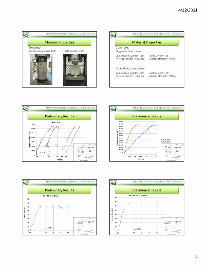
Material Properties
Concrete:Compression cylinder 4”x8” Split cylinder 4”x8”
Material Properties
Concrete: Single‐Bar Specimens:
Compression Cylinder 4”x8” Split Cylinder 4”x8”Average strength = 6400 psi Average strength = 450 psiAverage strength 6400 psi Average strength 450 psi
Group‐Effect Specimens:
Compression Cylinder 4”x8” Split Cylinder 4”x8”Average strength = 4850 psi Average strength = 400 psi
Preliminary Results
50,000
60,000
70,000
si)
No.8_90_0
0
10,000
20,000
30,000
40,000
,
Lead
Bar Stress (p
Slip (in)
1H 2H 3H 3V 4V
0.02 in
Preliminary Results
45 000
50,000
55,000
60,000
65,000
70,000
(psi)
0
5,000
10,000
15,000
20,000
25,000
30,000
35,000
40,000
45,000
0 0.02 0.04 0.06 0.08 0.1 0.12
Lead
Bar Stress
Slip (in)
No.8_90_22.5 1H
No.5_90_22.5 1H
60
70
80
i)
BE‐5‐90‐0‐2A Bar A
Preliminary Results
0
10
20
30
40
50
60
Lead
Bar Stress (ks
1H 2H 3H 3V 4V
0.1 inch
60
70
80
BE‐5‐90‐22.5‐2A Bar A
60
70
80BE‐5‐90‐22.5‐2A Bar A
Preliminary Results
0
10
20
30
40
50
60
Lead
Bar Stress (ksi)
1H 2H 3H 3V 4V
0.1 inch
0
10
20
30
40
50
Lead
Bar Stress (ksi)
1H 2H 3H 3V 4V
0.1 inch
4/12/2011
8
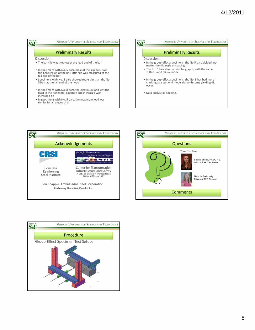
Preliminary Results
Discussion:• The bar slip was greatest at the lead end of the bar
• In specimens with No. 5 bars, most of the slip occurs at the bent region of the bar, little slip was measured at thethe bent region of the bar, little slip was measured at the tail end of the bar
• Specimens with No. 8 bars showed more slip than the No. 5 bars at the tail end of the hook
• In specimens with No. 8 bars, the maximum load was the least in the horizontal direction and increased with increased tilt
• In specimens with No. 5 bars, the maximum load was similar for all angles of tilt
Preliminary Results
Discussion:• In the group‐effect specimens, the No.5 bars yielded, no matter the tilt angle or spacing.
• The No. 5 bars also had similar graphs, with the same stiffness and failure mode.
• In the group‐effect specimens, the No. 8 bar had more cracking as a test end mode although some yielding did occur.
• Data analysis is ongoing.
Acknowledgements
Center for Transportation Infrastructure and Safety A National University Transportation
Center at Missouri S&T
Concrete Reinforcing
Steel Institute
Jon Knapp & Ambassador Steel CorporationGateway Building Products
Questions
Thank You from:
Lesley Sneed, Ph.D., P.E. Missouri S&T Professor
Comments
Nichole PodhorskyMissouri S&T Student
Procedure
Group‐Effect Specimen Test Setup: