Embed Size (px)
Citation preview

Crossing the motorway: air pressure waves due to lorries transit
Marco Petrangeli1, Alberto Viskovic
1
1 University “G. D’Annunzio” of Chieti-Pescara – Dept. of Engineering and Geology, Pescara, Italy
ABSTRACT: When proposing a slender parapet girder as an alternative to an awkward and
bulgy tubular truss beam providing pedestrian crossing across the Turin-Milan motorway, the
authors were hardly aware of the significant pressure waves caused by the passage of today’s
giant lorries speeding over 100 km/h. In highly congested motorways, these vehicles tends to
march at constant speed and spacing thus creating a pulsating effect that can lead to significant
vibrations in overpasses. The pressure waves created by their passage hardly lose its energy
before buffeting the deck since overpasses are generally placed as close as possible to the
minimum vertical clearance and large lorries tends to use all the available height. The field
measurements presented in the paper and the subsequent analyses hopefully provide some
helpful guidelines for footbridges overpasses across highway and motorways.
1 INTRODUCTION
The twenty-one pedestrian and cycle-pedestrian crossing along the Turin-Milan motorway were
built according the comfort (differential height in the pedestrian path and environmental
comfort) with the technical-economical and building phasing aspects.
With this aim were built 19 under passages and 2 overpasses (cycle-pedestrian bridges).
The firsts were easily built during the motorway enlargement (just taking care of a correct
works phasing).
About the overpasses, the interferences with the motorway were minimized pre-assembling the
whole span and placing it in one time. These two pedestrian bridges were initially designed with
two classic trussed lateral beams, with the service path level in between, used as balustrade also.
This structurally efficient solution (taking into account the nearly 50m of span) is not so
efficient for maintenance, as it brings to many “corners” were it is difficult the removing of dust
and where it is thus more probable the starting of corrosion.
We decided to design two solid double T girders, reducing their height but still using them as
balustrades. Considering the static scheme of single simply supported beam, the beam height
was shaped giving an arch profile, as visible in Figure 1 and in Figure 2, reaching a more light
and slender aspect together with a good structural efficiency.
Thus the beams height varies from 1.0m at the supports up to 1.80m in the mid-span. The
span between the supports is 46m and the pedestrian path is 2.50m large.
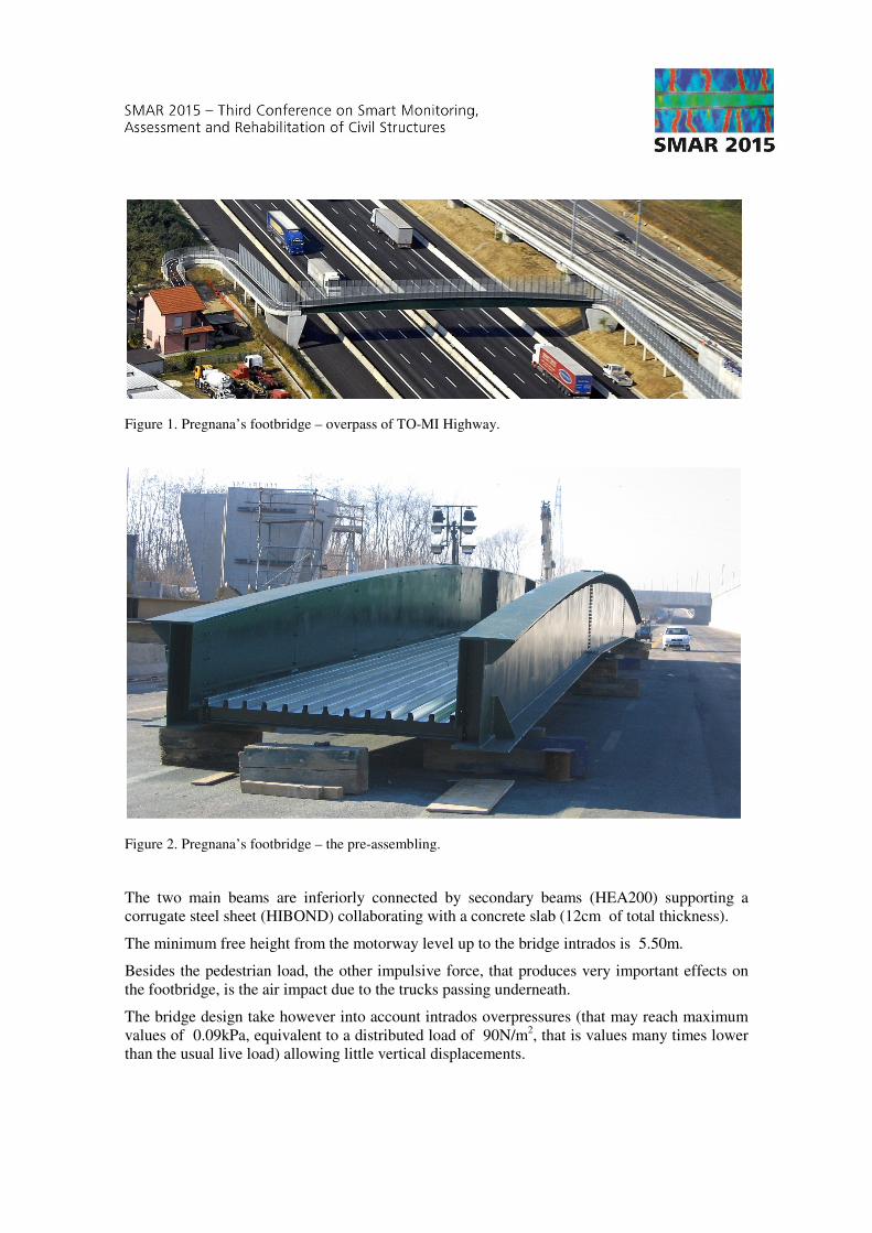
Figure 1. Pregnana’s footbridge – overpass of TO-MI Highway.
Figure 2. Pregnana’s footbridge – the pre-assembling.
The two main beams are inferiorly connected by secondary beams (HEA200) supporting a
corrugate steel sheet (HIBOND) collaborating with a concrete slab (12cm of total thickness).
The minimum free height from the motorway level up to the bridge intrados is 5.50m.
Besides the pedestrian load, the other impulsive force, that produces very important effects on
the footbridge, is the air impact due to the trucks passing underneath.
The bridge design take however into account intrados overpressures (that may reach maximum
values of 0.09kPa, equivalent to a distributed load of 90N/m2, that is values many times lower
than the usual live load) allowing little vertical displacements.

Figure 3. Pregnana’s footbridge – Longitudinal view with indication of remark sections.
But, as the overpressure wave has length not very shorter than one second, it is not a single
impulse but, on the contrary, it is an action with its own frequency spectrum. Therefore was
carried out a monitoring campaign to evaluate and to quantify possible dynamic effects.
2 PRESSURE WAVES AND DYNAMIC MONITORING
Twelve installed transducers are used to investigate the dynamic behavior related to air waves
impact due to trucks passing underneath, as follow:
� Pressure transducers monitor 4 sections above the 4 lanes towards Milan (Figure 3 and 4);
� Acceleration transducers control 3 sections (Figure 5) at mid-span, at the support and at L/4
(where L is the footbridge span).
In Figures 6 it is reported the more significant minute of registration with the P2 pressure
transducer, where was recorded the maximum pressure value (around 0,09kPa), as the P2
pressure transducer is placed on the axis of the lane more used by the lorries.
In Figure 7 it is reported the more significant minute of registration with the A5 acceleration
transducer, placed in the mid span, where there are the highest displacements.
3 ANALYSES AND ELABORATIONS
The recorded time histories of pressure (as that in Figure 6) show some isolated pick values,
corresponding to the bigger lorries passages (those with larger and higher frontal section),
together with minor pick values and also negative values corresponding to the lorries wake
turbulence.
The registrations refers to a “normal” vehicular traffic (for the Turin-Milan motorway) with
lorries running at velocity of around 80km/h.
In Figure 8 is reported the Fourier spectrum of the P2 registration, in semi-logarithmic scale to
better show the lower frequencies.

Figure 4. Pregnana’s footbridge – Position of pressure transducers in the remark sections.
Figure 5. Pregnana’s footbridge – Position of acceleration transducers at one support, at ¼ of span and in the mid span sections.
Figure 6. Pregnana’s footbridge – Pressure transducer P2, the more significant minute of registration.
Figure 7. Pregnana’s footbridge – Acceleration transducer A5, in the mid span, the more significant minute of filtered registration.
Those lower frequencies (0,281Hz, 0,439Hz, 0,647Hz and 0,940Hz) are corresponding to
pressure pick values of higher energy content.
However those main frequencies are all relatively far from the bridge main own frequencies
evaluated by a numerical model (Figure 9) and also obtained through the Fourier spectrum of
the registrations taken by the acceleration transducers.
Combining the registrations of the two accelerometers in the mid span, it is possible to identify
the flexional first mode at 1,77Hz, while analyzing the differences between the same two
registrations is obtained the first torsion mode at 4,77Hz.
Combining the registrations of the two accelerometers at ¼ of the span, it is possible to identify
the flexional second mode at 81,36Hz, the torsion second mode, etc..
It is important to note that these last anti-symmetric modes of vibration may be those more
excited by the anti-symmetric actions of the lorries running in the two opposite external lanes,
Storia temporale di pressione P2
-0.10
-0.08
-0.06
-0.04
-0.02
0.00
0.02
0.04
0.06
0.08
0.10
0 10 20 30 40 50 60
tempo [s]
pre
ss
ion
e [
kP
a]
Accelerogramma 5 filtrato
-0.4
-0.3
-0.2
-0.1
0
0.1
0.2
0.3
0.4
0 10 20 30 40 50 60
tempo [s]
accele
razio
ne [
m/s
2]

Figure 8. Pregnana’s footbridge – Fourier spectrum of pressure transducer P2 registration.
Figure 9. Pregnana’s footbridge – F.E.M. Model.
but the pressure waves frequency content is very far from the frequencies of these superior
modes of vibrations.
On the contrary, it is possible to notice that 0,940Hz (the pressure waves higher frequency pick
value) is nearly a sub-multiple of both the first and the second bridge mode frequencies (first
flexional and first torsion modes), but these modes are those less involved because of the
position of the more used lanes.
Moreover it is important also to take into account the spatial 3D form of the pressure waves: in
Figure 10 it is possible to note the time shift of the pressure pick value from the lane axis with
the lorry (P2 and P7) to the adjacent lane axis (P9 and P10). This time shifting in the actions, on
different near sections of the bridge, means that the wave front has an arch shape in its
horizontal sections and this fact reduces the possibility of resonance with the bridge’s modes of
vibration.
Thus it is possible to say that the registered pressure waves have geometrical and dynamic
characteristic that cannot cause significant resonance phenomena in the bridge.
Spettro di Fourier della pressione P2
0.00
0.02
0.04
0.06
0.08
0.10
0.12
0 1 10 100
Frequenza [Hz]
Fo
uri
er

Figure 10. Pregnana’s footbridge at one pressure wave passage.
This because the energy content is relatively low
shifting among the actions in
from which are more excited the brid
air pressure frequencies.
Moreover, the waves actions have
oscillations state, before the arriving of another pressure wave action
The low dynamic effect of this actions is corroborated by the acceleration transducer
registrations (Figure 7). After some necessary signal filtering (to eliminate aliasing phenomena
due to noise) the registered acceleration may be integrated to h
Figure 11) and another time integrated to have the displacement histories
The maximum displacement are obtained in the mid
A5) and it is around 2mm, in vertical direction
absence of resonance phenomena
4 CONCLUSIONS
The pressure waves have a) a
the bridge and c) dynamic characteristic
cause significant resonance phenomena in the bridge.
At the same time, the bridge shape and
optimization in terms of time for the building up and in terms of total costs.
Pregnana’s footbridge – Pressure transducers P2, P7, P9 and P10, the synchronized
This because the energy content is relatively low, because the 3D wave front causes time
in adjacent bridge sections and also because the lorries run on lanes
from which are more excited the bridge modes of vibration with frequencies
the waves actions have so short durations that the bridge rapidly reach a free
oscillations state, before the arriving of another pressure wave action.
The low dynamic effect of this actions is corroborated by the acceleration transducer
After some necessary signal filtering (to eliminate aliasing phenomena
the registered acceleration may be integrated to have the velocity histories
another time integrated to have the displacement histories (as in Figure 1
The maximum displacement are obtained in the mid-span (Figure 12, acceleration transducer
, in vertical direction, sufficiently modest to confirm
phenomena.
3D geometrical shape, b) a lateral position respect the mid
dynamic characteristic with low energy contents, in such a way
cause significant resonance phenomena in the bridge.
the same time, the bridge shape and the choices about the materials used
time for the building up and in terms of total costs.
synchronized registration
ve front causes time
the lorries run on lanes
more far from the
that the bridge rapidly reach a free
The low dynamic effect of this actions is corroborated by the acceleration transducer
After some necessary signal filtering (to eliminate aliasing phenomena
ave the velocity histories (as in
in Figure 12).
acceleration transducer
confirm the substantial
respect the mid span of
, in such a way that cannot
used assure an high
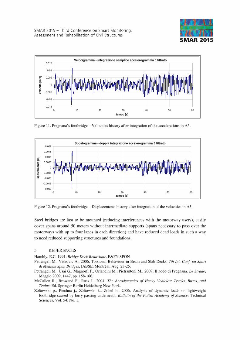
Figure 11. Pregnana’s footbridge – Velocities history after integration of the accelerations in A5.
Figure 12. Pregnana’s footbridge – Displacements history after integration of the velocities in A5.
Steel bridges are fast to be mounted (reducing interferences with the motorway users), easily
cover spans around 50 meters without intermediate supports (spans necessary to pass over the
motorways with up to four lanes in each direction) and have reduced dead loads in such a way
to need reduced supporting structures and foundations.
5 REFERENCES
Hambly, E.C. 1991, Bridge Deck Behaviour, E&FN SPON
Petrangeli M., Viskovic A., 2006, Torsional Behaviour in Beam and Slab Decks, 7th Int. Conf. on Short
& Medium Span Bridges, IABSE, Montréal, Aug. 23-25.
Petrangeli M., Usai G., Magnorfi F., Orlandini M., Pietrantoni M., 2009, Il nodo di Pregnana. Le Strade,
Maggio 2009, 1447, pp. 158-166.
McCallen R., Browand F., Ross J., 2004, The Aerodynamics of Heavy Vehicles: Trucks, Buses, and
Trains, Ed. Springer Berlin Heidelberg New York.
Zółtowski p., Piechna j., Zółtowski k., Zobel h., 2006, Analysis of dynamic loads on lightweight
footbridge caused by lorry passing underneath, Bulletin of the Polish Academy of Science, Technical
Sciences, Vol. 54, No. 1.
Velocigramma - integrazione semplice accelerogramma 5 filtrato
-0.015
-0.01
-0.005
0
0.005
0.01
0.015
0 10 20 30 40 50 60
tempo [s]
ve
loc
ità
[m
/s]
Spostogramma - doppia integrazione accelerogramma 5 filtrato
-0.002
-0.0015
-0.001
-0.0005
0
0.0005
0.001
0.0015
0.002
0 10 20 30 40 50 60
tempo [s]
sp
osta
men
to [
m]