Embed Size (px)
Citation preview
Cross-VM Information Leaksin FPGA-Accelerated Cloud Environments
Ilias Giechaskiel†Independent Researcher
London, United [email protected]
Shanquan Tian†Yale University
New Haven, CT, [email protected]
Jakub SzeferYale University
New Haven, CT, [email protected]
Abstract—The availability of FPGAs in cloud data centers of-fers rapid, on-demand access to hardware compute resources thatusers can configure to their own needs. However, the low-levelaccess to the hardware FPGA and associated resources such asPCIe, SSD, or DRAM also opens up threats of malicious attackersuploading designs that are able to infer information about otherusers or about the cloud infrastructure itself. In particular, thiswork presents a new, fast PCIe-contention-based channel thatis able to transmit data between different FPGA-acceleratedvirtual machines with bandwidths reaching 2kbps with 97%accuracy. This paper further demonstrates that the PCIe receivercircuits are able to not just receive covert transmissions, but canalso perform fine-grained monitoring of the PCIe bus or detectdifferent types of activities from other users’ FPGA-acceleratedvirtual machines based on their PCIe traffic signatures. Beyondleaking information across different virtual machines, the abilityto monitor the PCIe bandwidth over hours or days can be used toestimate the data center utilization and map the behavior of theother users. The paper also introduces further novel threats inFPGA-accelerated instances, including contention due to sharedNVMe SSDs as well as thermal monitoring to identify FPGAco-location using the DRAM modules attached to the FPGAboards. This is the first work to demonstrate that it is possibleto break the separation of privilege in FPGA-accelerated cloudenvironments, and highlights that defenses for public clouds usingFPGAs need to consider PCIe, SSD, and DRAM resources as partof the attack surface that should be protected.
I. INTRODUCTION
Public cloud infrastructures with FPGA-accelerated virtualmachine (VM) instances allow for easy, on-demand accessto reconfigurable hardware that users can program with theirown designs. The FPGA-accelerated instances can be used toaccelerate machine learning, image and video manipulation, orgenomic applications, for example [5]. The potential benefitsof the instances with FPGAs have resulted in numerouscloud providers including Amazon Web Services (AWS) [9],Alibaba [3], Baidu [16], Huawei [27], Nimbix [35], andTencent [39], giving public users direct access to FPGAs.However, allowing users low-level access to upload their ownhardware designs has resulted in serious implications for thesecurity of the cloud users and the cloud infrastructure itself.
Several recent works have considered the security impli-cations of shared (“multi-tenant”) FPGAs in the cloud, andhave demonstrated covert-channel [23] and side-channel [25]
† The first two authors contributed equally to this work. This work wassupported in part by NSF grant 1901901.
attacks. However, today’s cloud providers, such as AWS withtheir F1 instances, only offer “single-tenant” access to FPGAs.In the single-tenant setting, each FPGA is fully dedicated tothe one user who rents it, while many other users may bein parallel using their separate, dedicated FPGAs which arewithin the same server. Once an FPGA is released by a user, itcan then be assigned to the next user who rents it. This can leadto temporal thermal covert channels [41], where heat generatedby one circuit can be later observed by other circuits that areloaded onto the same FPGA. Such channels are slow (lessthan 1 bps), and are only suitable for covert communication,since they require the two parties to coordinate and keep beingscheduled on the same physical hardware one after the other.
Other means of covert communication in the single-tenantsetting do not require being assigned to the same FPGA chip.For example, multiple FPGA boards in servers share the samepower supply, and prior work has shown the potential forsuch shared power supplies to leak information between FPGAboards [24]. However, the resulting covert channel was slow(less than 10 bps) and was only demonstrated in a lab setup.
Another single-tenant security topic that has been previouslyexplored is that of fingerprinting FPGA instances using Phys-ical Unclonable Functions (PUFs) [40], [42]. Fingerprintingallows users to partially map the infrastructures and get someinsights about the allocation of FPGAs (e.g., how likely auser is to be re-assigned to the same physical FPGA theyused before), but fingerprinting by itself does not lead toinformation leaks. A more recent fingerprinting-related workexplored mapping FPGA infrastructures using PCIe contentionto find which FPGAs are co-located in the same Non-UniformMemory Access (NUMA) node within a server [43]. However,no prior work has successfully launched a cross-VM covert-or side-channel attack in a real cloud FPGA setting.
By contrast, this work shows for the first time that sharedresources can be used to leak information across separate vir-tual machines running on the FPGA-accelerated F1 instancesin AWS data centers. In particular, we use the contention of thePCIe bus to not only demonstrate a new, fast covert channel(reaching up to 2 kbps), but also to identify patterns of activitybased on the PCIe signatures of different Amazon FPGAImages (AFIs) used by other users. Our attacks do not requirespecial privileges or potentially malicious circuits such asRing Oscillators (ROs) or Time-to-Digital Converters (TDCs),
and can thus not easily be detected through static analysisor Design Rule Checks (DRCs) that cloud providers mayperform. We further introduce two new methods of findingco-located instances that are in the same physical server: (a)through resource contention of the Non-Volatile Memory Ex-press (NVMe) SSDs that are accessible from each F1 instance,and (b) through the common thermal signatures obtainedfrom the decay rates of each FPGA’s DRAM modules. Ourwork therefore shows that single-tenant attacks in real FPGA-accelerated cloud environments are practical, and demonstratesseveral ways to infer information about the operations of othercloud users and their FPGA-accelerated virtual machines.
A. Contributions
In summary, the contributions of this work are:1) The demonstration of the first covert channel between
separate F1 instance virtual machines, reaching 2 kbpswith 97% accuracy.
2) Cross-VM side-channel leaks that reveal informationabout the behavior of different users through the PCIesignatures of their Amazon FPGA Images (AFIs).
3) A long-term monitoring approach of data center activitythrough PCIe contention.
4) The identification of an alternative, SSD-based co-location mechanism and possible covert channel be-tween separate F1 users.
5) A new DRAM-based co-location mechanism to identifyF1 instances which are on separate NUMA nodes, butshare the same server.
B. Responsible Disclosure
Our findings and a copy of this paper have been shared withthe AWS security team.
C. Paper Organization
The remainder of the paper is organized as follows. Sec-tion II provides the background on today’s deployments ofFPGAs in public cloud data centers. Section III discussestypical FPGA-accelerated cloud servers and PCIe contentionthat can occur among the FPGAs, while Section IV evaluatesour fast, PCIe-based, cross-VM channel. Using the ideas fromthe covert channel, Section V investigates how to infer infor-mation about other VMs through their PCIe traffic patterns,with Section VI revolving around long-term PCIe monitoringof data center activity. Section VII then presents an alternativecontention mechanism due to shared SSDs among FPGA-accelerated instances, while Section VIII introduces a new,thermal-based co-location mechanism. The paper ends with alist of related work in Section IX, and concludes in Section X.
II. BACKGROUND
This section provides a brief background on FPGAs avail-able in public cloud computing data centers, with a focus onthe F1 instances from Amazon Web Services (AWS) [9] thatare evaluated in this work.
Fig. 1: Prior work suggested that AWS servers contain 8 FPGAs,equally divided between two NUMA nodes [43].
A. AWS F1 Instance Architecture
AWS has offered FPGA-accelerated virtual machine in-stances to users since late 2016 [4]. These so-calledF1 instances are available in three sizes: f1.2xlarge,f1.4xlarge, and f1.16xlarge, where the instance namerepresents twice the number of FPGAs it contains (sof1.2xlarge has 1 FPGA, while f1.4xlarge has 2, andf1.16xlarge has 8 FPGAs). Each instance is allocated 8virtual CPUs (vCPUs), 122GiB of DRAM, and 470GB ofNVMe SSD storage per FPGA. For example, f1.4xlargeinstances have 16 vCPUS, 244GiB of DRAM, and 940GBof SSD space [9], since they contain 2 FPGAs.
Each FPGA board is attached to the server over a x16 PCIeGen 3 bus. In addition, each FPGA board contains four DDR4DRAM chips, totaling 64GiB of memory per FPGA board [9].These memories are separate from the server’s DRAM andare directly accessible by each FPGA. The F1 instances useVirtex UltraScale+ XCVU9P chips [9], which contain over 1.1million lookup tables (LUTs), 2.3 million flip-flops (FFs), and6.8 thousand Digital Signal Processing (DSP) blocks [47].
As has recently been shown, each server contains 8 FPGAboards, which are evenly split between two Non-UniformMemory Access (NUMA) nodes [43]. The AWS server ar-chitecture, as deduced by Tian et al. [43], is shown inFigure 1. Due to this architecture, an f1.2xlarge instancemay be on the same NUMA node as up to three otherf1.2xlarge instances, or on the same NUMA node asone other f1.2xlarge instance and one f1.4xlargeinstance (which uses 2 FPGAs). Conversely, an f1.4xlargeinstance may share the same NUMA node with up to twof1.2xlarge instances, or one f1.4xlarge instance. Fi-nally, as f1.16xlarge instances use up all 8 FPGAs in theserver, they do not share any resources with other instances,since both NUMA nodes of the server are fully occupied.
B. Programming AWS F1 Instances
Users utilizing F1 instances do not retain entirely unre-stricted control to the underlying hardware, but instead needto adapt their hardware designs to fit within a predefinedarchitecture. In particular, user designs are defined as “CustomLogic (CL)” modules that interact with external interfacesthrough the cloud-provided “Shell”, which hides physicalaspects such as clocking logic and I/O pinouts (including for
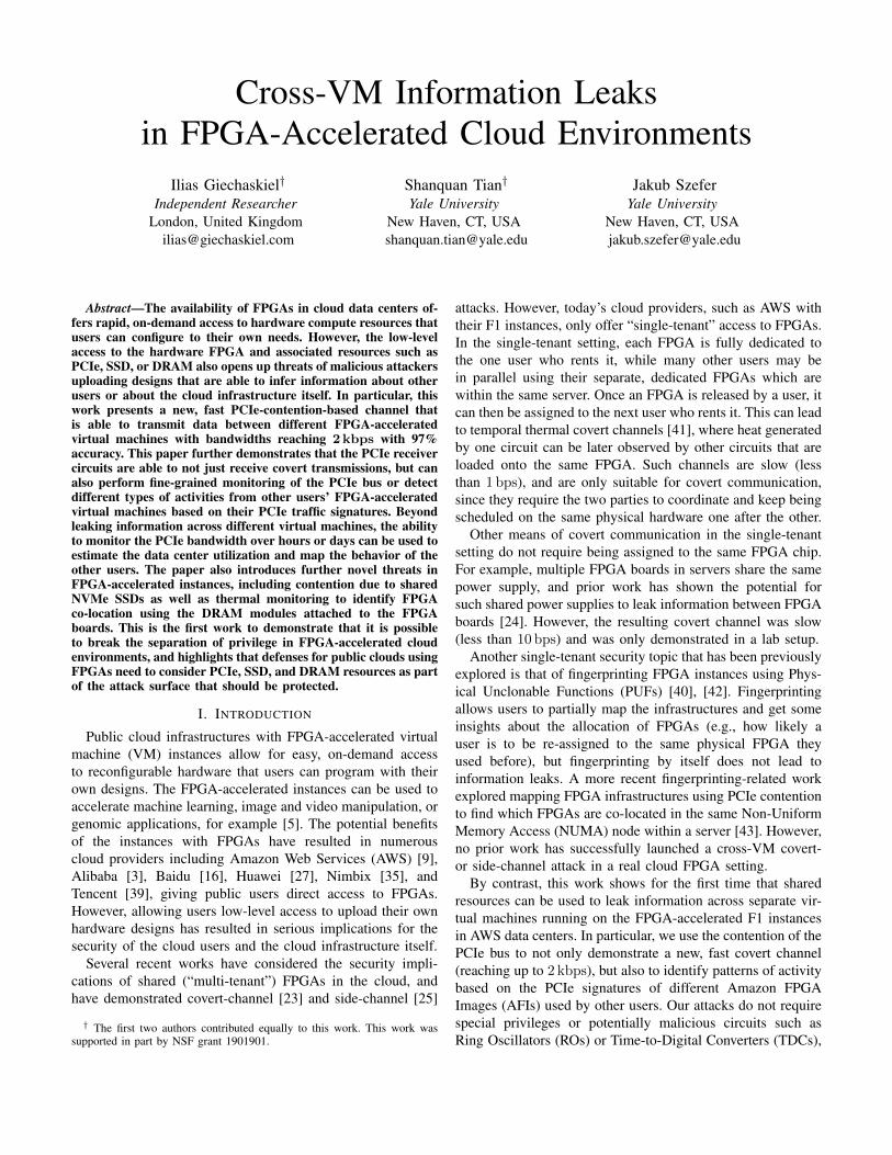
Fig. 2: Our deduced PCIe configuration for F1 servers based on the experiments in this work: each CPU has two PCIe links, each of whichprovides connectivity to two FPGAs and an NVMe SSD through a PCIe switch.
PCIe and DRAM) [23], [42]. This restrictive Shell interfacefurther prevents users from accessing identifier resources, suchas eFUSE and Device DNA primitives, which could be usedto distinguish between different FPGA boards [23], [42].Finally, users cannot directly upload bitstreams to the FPGAs.Instead, they generate a Design Checkpoint (DCP) file usingXilinx’s tools and then provide it to Amazon to create thefinal bitstream (Amazon FPGA Image, or AFI), after it haspassed a number of Design Rule Checks (DRCs). The checks,for example, include prohibiting combinatorial loops such asRing Oscillators (ROs) as a way of protecting the underlyinghardware [22], [23], though alternative designs bypassing theserestrictions have been proposed [23], [38].
III. PCIE CONTENTION IN CLOUD FPGAS
The user’s Custom Logic running on the FPGA instancescan use the Shell to communicate with the server through thePCIe bus. Users cannot directly control the PCIe transactions,but instead perform simple reads and writes to predefinedaddress ranges through the Shell. These memory accessesget translated into PCIe commands and PCIe data transfersbetween the server and the FPGA. The users may also set upDirect Memory Access (DMA) transfers between the FPGAand the server. By designing hardware modules with low logicoverhead, users can generate transfers fast enough to saturatethe PCIe bandwidth. In fact, because of the shared PCIe buswithin each Non-Uniform Memory Access (NUMA) node,these transfers can create interference and bus contention thataffects the PCIe bandwidth of other users. The resulting perfor-mance degradation can be used for detecting co-location [43]or, as we show in this work, for fast covert- and side-channelattacks, in effect breaking separation of privilege betweenotherwise logically and physically separate VM instances.
Figure 1 shows the assumed AWS server configuration with8 FPGAs per server, based on prior work by Tian et al. [43]and publicly available information on AWS F1 instances [9],[13]. AWS servers containing FPGAs have two Intel Xeon E5-2686 v4 (Broadwell) processors, connected through an IntelQuickPath Interconnect (QPI) link. Each processor forms itsown NUMA node with its associated DRAM and four FPGAsattached as PCIe devices.
In our covert-channel analysis (Section IV), we show thatthe communication bandwidth is not identical for all pairs ofFPGAs in a NUMA node. In particular, this suggests that the4 PCIe devices are not directly connected to each CPU, but
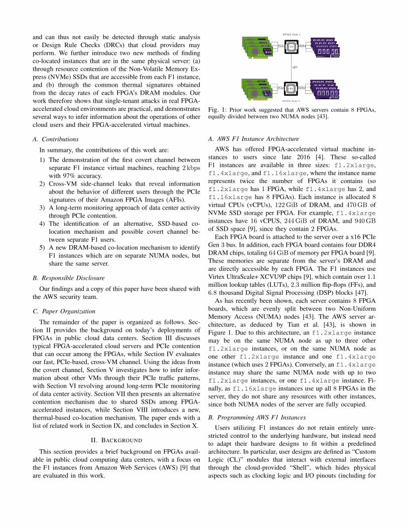
Fig. 3: Example cross-VM covert communication: The transmitter(Alice) sends the ASCII byte ‘H’, represented as 01001000 in binary,to the receiver (Bob) in 8 measurement intervals by stressing herPCIe bandwidth to transmit a 1 and remaining idle to transmit a 0. IfBob’s FPGA bandwidth B drops below a threshold T , he detects a1, otherwise a 0 is detected. To ensure no residual effects after eachtransmission, the time difference δ between successive measurementsis slightly larger than the transmission duration d.
instead likely go through two separate switches, forming thehierarchy shown in Figure 2. Although not publicly confirmedby AWS, this topology is similar to the one described for P4dinstances, which contain 8 GPUs [7]. As a result, althoughall 4 FPGAs in a NUMA node contend with each other, thecovert-channel bandwidth is highest amongst those sharing aPCIe switch, due to the bottleneck imposed by the shared link.
IV. PCIE-BASED CROSS-VM COVERT CHANNEL
In this section we describe our implementation for the firstcross-VM covert-channel on public cloud FPGAs using PCIecontention (Section IV-A), and discuss our experimental setup(Section IV-B). We then analyze bandwidth vs. accuracy trade-offs (Section IV-C), before investigating the impact of receiverand transmitter transfer sizes on the covert-channel accuracyfor a given covert-channel bandwidth (Section IV-D). Sidechannels and information leaks based on PCIe contention fromother VMs are discussed in Section V, while Section VI showslong-term PCIe-based monitoring of data center activity.
A. Covert-Channel Implementation
Our covert-channel is based on saturating the PCIe linkbetween the FPGA and the server, so, at their core, boththe transmitter and the receiver consist of a) an FPGA imagethat responds to PCIe requests with minimal latency, and b)software that attaches to the FPGA and repeatedly writes to themapped Base Address Register (BAR). The transmitter stressesits PCIe link to transmit a 1 but remains idle to transmit a
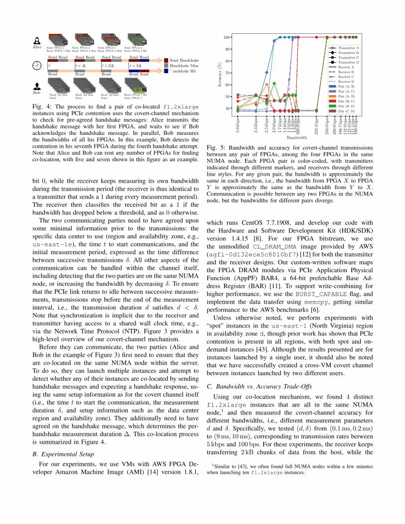
Fig. 4: The process to find a pair of co-located f1.2xlargeinstances using PCIe contention uses the covert-channel mechanismto check for pre-agreed handshake messages: Alice transmits thehandshake message with her first FPGA, and waits to see if Bobacknowledges the handshake message. In parallel, Bob measuresthe bandwidths of all his FPGAs. In this example, Bob detects thecontention in his seventh FPGA during the fourth handshake attempt.Note that Alice and Bob can rent any number of FPGAs for findingco-location, with five and seven shown in this figure as an example.
bit 0, while the receiver keeps measuring its own bandwidthduring the transmission period (the receiver is thus identical toa transmitter that sends a 1 during every measurement period).The receiver then classifies the received bit as a 1 if thebandwidth has dropped below a threshold, and as 0 otherwise.
The two communicating parties need to have agreed uponsome minimal information prior to the transmissions: thespecific data center to use (region and availability zone, e.g.,us-east-1e), the time t to start communications, and theinitial measurement period, expressed as the time differencebetween successive transmissions δ. All other aspects of thecommunication can be handled within the channel itself,including detecting that the two parties are on the same NUMAnode, or increasing the bandwidth by decreasing δ. To ensurethat the PCIe link returns to idle between successive measure-ments, transmissions stop before the end of the measurementinterval, i.e., the transmission duration d satisfies d < δ.Note that synchronization is implicit due to the receiver andtransmitter having access to a shared wall clock time, e.g.,via the Network Time Protocol (NTP). Figure 3 provides ahigh-level overview of our covert-channel mechanism.
Before they can communicate, the two parties (Alice andBob in the example of Figure 3) first need to ensure that theyare co-located on the same NUMA node within the server.To do so, they can launch multiple instances and attempt todetect whether any of their instances are co-located by sendinghandshake messages and expecting a handshake response, us-ing the same setup information as for the covert channel itself(i.e., the time t to start the communication, the measurementduration δ, and setup information such as the data centerregion and availability zone). They additionally need to haveagreed on the handshake message, which determines the per-handshake measurement duration ∆. This co-location processis summarized in Figure 4.
B. Experimental Setup
For our experiments, we use VMs with AWS FPGA De-veloper Amazon Machine Image (AMI) [14] version 1.8.1,
5.0
kb
ps
3.3
kb
ps
2.5
kb
ps
2.0
kb
ps
1.7
kb
ps
1.4
kb
ps
1.2
kb
ps
1.1
kb
ps
1.0
kb
ps
500.
0b
ps
333.
3b
ps
250.
0b
ps
200.
0b
ps
166.
7b
ps
142.
9b
ps
125.
0b
ps
111.
1b
ps
100.
0b
ps
Bandwidth
40
50
60
70
80
90
100
Acc
ura
cy(%
)
Transmitter A
Transmitter B
Transmitter C
Transmitter D
Receiver A
Receiver B
Receiver C
Receiver D
Pair (A, B)
Pair (A, C)
Pair (A, D)
Pair (B, C)
Pair (B, D)
Pair (C, D)
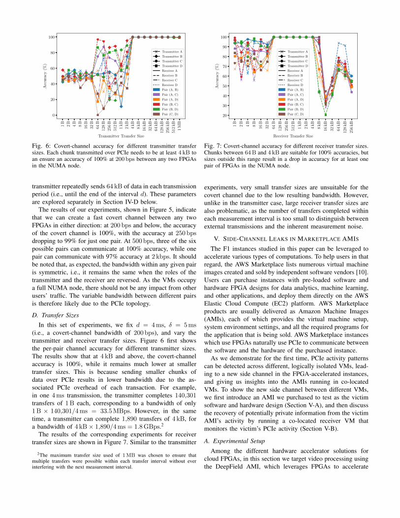
Fig. 5: Bandwidth and accuracy for covert-channel transmissionsbetween any pair of FPGAs, among the four FPGAs in the sameNUMA node. Each FPGA pair is color-coded, with transmittersindicated through different markers, and receivers through differentline styles. For any given pair, the bandwidth is approximately thesame in each direction, i.e., the bandwidth from FPGA X to FPGAY is approximately the same as the bandwidth from Y to X .Communication is possible between any two FPGAs in the NUMAnode, but the bandwidths for different pairs diverge.
which runs CentOS 7.7.1908, and develop our code withthe Hardware and Software Development Kit (HDK/SDK)version 1.4.15 [8]. For our FPGA bitstream, we usethe unmodified CL_DRAM_DMA image provided by AWS(agfi-0d132ece5c8010bf7) [12] for both the transmitterand the receiver designs. Our custom-written software mapsthe FPGA DRAM modules via PCIe Application PhysicalFunction (AppPF) BAR4, a 64-bit prefetchable Base Ad-dress Register (BAR) [11]. To support write-combining forhigher performance, we use the BURST_CAPABLE flag, andimplement the data transfer using memcpy, getting similarperformance to the AWS benchmarks [6].
Unless otherwise noted, we perform experiments with“spot” instances in the us-east-1 (North Virginia) regionin availability zone d, though prior work has shown that PCIecontention is present in all regions, with both spot and on-demand instances [43]. Although the results presented are forinstances launched by a single user, it should also be notedthat we have successfully created a cross-VM covert channelbetween instances launched by two different users.
C. Bandwidth vs. Accuracy Trade-Offs
Using our co-location mechanism, we found 4 distinctf1.2xlarge instances that are all in the same NUMAnode,1 and then measured the covert-channel accuracy fordifferent bandwidths, i.e., different measurement parametersd and δ. Specifically, we tested (d, δ) from (0.1ms, 0.2ms)to (9ms, 10ms), corresponding to transmission rates between5 kbps and 100 bps. For these experiments, the receiver keepstransferring 2 kB chunks of data from the host, while the
1Similar to [43], we often found full NUMA nodes within a few minuteswhen launching ten f1.2xlarge instances.
1B
2B
4B
8B
16B
32B
64B
128
B
256
B
512
B
1kB
2kB
4kB
8kB
16kB
32kB
64kB
128
kB
256
kB
512
kB
1M
B
Transmitter Transfer Size
0
20
40
60
80
100
Acc
ura
cy(%
)
Transmitter A
Transmitter B
Transmitter C
Transmitter D
Receiver A
Receiver B
Receiver C
Receiver D
Pair (A, B)
Pair (A, C)
Pair (A, D)
Pair (B, C)
Pair (B, D)
Pair (C, D)
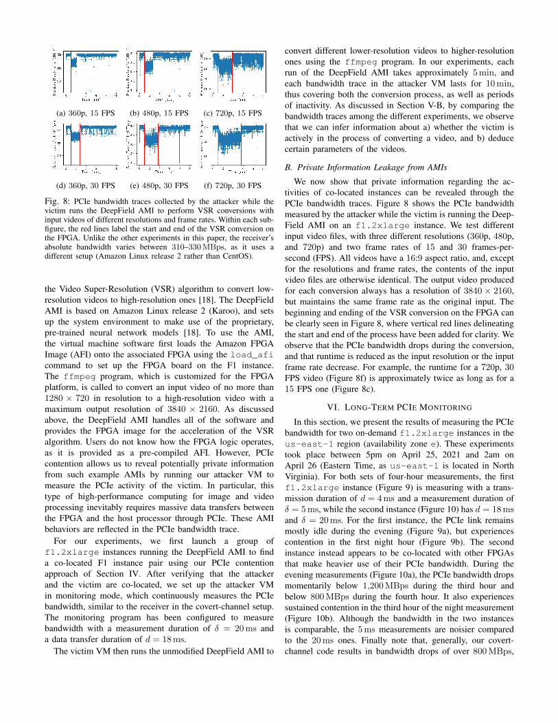
Fig. 6: Covert-channel accuracy for different transmitter transfersizes. Each chunk transmitted over PCIe needs to be at least 4 kB toan ensure an accuracy of 100% at 200 bps between any two FPGAsin the NUMA node.
transmitter repeatedly sends 64 kB of data in each transmissionperiod (i.e., until the end of the interval d). These parametersare explored separately in Section IV-D below.
The results of our experiments, shown in Figure 5, indicatethat we can create a fast covert channel between any twoFPGAs in either direction: at 200 bps and below, the accuracyof the covert channel is 100%, with the accuracy at 250 bpsdropping to 99% for just one pair. At 500 bps, three of the sixpossible pairs can communicate at 100% accuracy, while onepair can communicate with 97% accuracy at 2 kbps. It shouldbe noted that, as expected, the bandwidth within any given pairis symmetric, i.e., it remains the same when the roles of thetransmitter and the receiver are reversed. As the VMs occupya full NUMA node, there should not be any impact from otherusers’ traffic. The variable bandwidth between different pairsis therefore likely due to the PCIe topology.
D. Transfer Sizes
In this set of experiments, we fix d = 4ms, δ = 5ms(i.e., a covert-channel bandwidth of 200 bps), and vary thetransmitter and receiver transfer sizes. Figure 6 first showsthe per-pair channel accuracy for different transmitter sizes.The results show that at 4 kB and above, the covert-channelaccuracy is 100%, while it remains much lower at smallertransfer sizes. This is because sending smaller chunks ofdata over PCIe results in lower bandwidth due to the as-sociated PCIe overhead of each transaction. For example,in one 4ms transmission, the transmitter completes 140,301transfers of 1B each, corresponding to a bandwidth of only1B × 140,301/4ms = 33.5MBps. However, in the sametime, a transmitter can complete 1,890 transfers of 4 kB, fora bandwidth of 4 kB× 1,890/4ms = 1.8GBps.2
The results of the corresponding experiments for receivertransfer sizes are shown in Figure 7. Similar to the transmitter
2The maximum transfer size used of 1MB was chosen to ensure thatmultiple transfers were possible within each transfer interval without everinterfering with the next measurement interval.
1B
2B
4B
8B
16B
32B
64B
128
B
256
B
512
B
1kB
2kB
4kB
8kB
16kB
32kB
64kB
128
kB
256
kB
Receiver Transfer Size
20
30
40
50
60
70
80
90
100
Acc
ura
cy(%
)
Transmitter A
Transmitter B
Transmitter C
Transmitter D
Receiver A
Receiver B
Receiver C
Receiver D
Pair (A, B)
Pair (A, C)
Pair (A, D)
Pair (B, C)
Pair (B, D)
Pair (C, D)
Fig. 7: Covert-channel accuracy for different receiver transfer sizes.Chunks between 64B and 4 kB are suitable for 100% accuracies, butsizes outside this range result in a drop in accuracy for at least onepair of FPGAs in the NUMA node.
experiments, very small transfer sizes are unsuitable for thecovert channel due to the low resulting bandwidth. However,unlike in the transmitter case, large receiver transfer sizes arealso problematic, as the number of transfers completed withineach measurement interval is too small to distinguish betweenexternal transmissions and the inherent measurement noise.
V. SIDE-CHANNEL LEAKS IN MARKETPLACE AMIS
The F1 instances studied in this paper can be leveraged toaccelerate various types of computations. To help users in thatregard, the AWS Marketplace lists numerous virtual machineimages created and sold by independent software vendors [10].Users can purchase instances with pre-loaded software andhardware FPGA designs for data analytics, machine learning,and other applications, and deploy them directly on the AWSElastic Cloud Compute (EC2) platform. AWS Marketplaceproducts are usually delivered as Amazon Machine Images(AMIs), each of which provides the virtual machine setup,system environment settings, and all the required programs forthe application that is being sold. AWS Marketplace instanceswhich use FPGAs naturally use PCIe to communicate betweenthe software and the hardware of the purchased instance.
As we demonstrate for the first time, PCIe activity patternscan be detected across different, logically isolated VMs, lead-ing to a new side channel in the FPGA-accelerated instances,and giving us insights into the AMIs running in co-locatedVMs. To show the new side channel between different VMs,we first introduce an AMI we purchased to test as the victimsoftware and hardware design (Section V-A), and then discussthe recovery of potentially private information from the victimAMI’s activity by running a co-located receiver VM thatmonitors the victim’s PCIe activity (Section V-B).
A. Experimental Setup
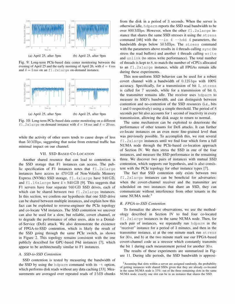
Among the different hardware accelerator solutions forcloud FPGAs, in this section we target video processing usingthe DeepField AMI, which leverages FPGAs to accelerate
(a) 360p, 15 FPS (b) 480p, 15 FPS (c) 720p, 15 FPS
(d) 360p, 30 FPS (e) 480p, 30 FPS (f) 720p, 30 FPS
Fig. 8: PCIe bandwidth traces collected by the attacker while thevictim runs the DeepField AMI to perform VSR conversions withinput videos of different resolutions and frame rates. Within each sub-figure, the red lines label the start and end of the VSR conversion onthe FPGA. Unlike the other experiments in this paper, the receiver’sabsolute bandwidth varies between 310–330MBps, as it uses adifferent setup (Amazon Linux release 2 rather than CentOS).
the Video Super-Resolution (VSR) algorithm to convert low-resolution videos to high-resolution ones [18]. The DeepFieldAMI is based on Amazon Linux release 2 (Karoo), and setsup the system environment to make use of the proprietary,pre-trained neural network models [18]. To use the AMI,the virtual machine software first loads the Amazon FPGAImage (AFI) onto the associated FPGA using the load_aficommand to set up the FPGA board on the F1 instance.The ffmpeg program, which is customized for the FPGAplatform, is called to convert an input video of no more than1280 × 720 in resolution to a high-resolution video with amaximum output resolution of 3840 × 2160. As discussedabove, the DeepField AMI handles all of the software andprovides the FPGA image for the acceleration of the VSRalgorithm. Users do not know how the FPGA logic operates,as it is provided as a pre-compiled AFI. However, PCIecontention allows us to reveal potentially private informationfrom such example AMIs by running our attacker VM tomeasure the PCIe activity of the victim. In particular, thistype of high-performance computing for image and videoprocessing inevitably requires massive data transfers betweenthe FPGA and the host processor through PCIe. These AMIbehaviors are reflected in the PCIe bandwidth trace.
For our experiments, we first launch a group off1.2xlarge instances running the DeepField AMI to finda co-located F1 instance pair using our PCIe contentionapproach of Section IV. After verifying that the attackerand the victim are co-located, we set up the attacker VMin monitoring mode, which continuously measures the PCIebandwidth, similar to the receiver in the covert-channel setup.The monitoring program has been configured to measurebandwidth with a measurement duration of δ = 20ms anda data transfer duration of d = 18ms.
The victim VM then runs the unmodified DeepField AMI to
convert different lower-resolution videos to higher-resolutionones using the ffmpeg program. In our experiments, eachrun of the DeepField AMI takes approximately 5min, andeach bandwidth trace in the attacker VM lasts for 10min,thus covering both the conversion process, as well as periodsof inactivity. As discussed in Section V-B, by comparing thebandwidth traces among the different experiments, we observethat we can infer information about a) whether the victim isactively in the process of converting a video, and b) deducecertain parameters of the videos.
B. Private Information Leakage from AMIs
We now show that private information regarding the ac-tivities of co-located instances can be revealed through thePCIe bandwidth traces. Figure 8 shows the PCIe bandwidthmeasured by the attacker while the victim is running the Deep-Field AMI on an f1.2xlarge instance. We test differentinput video files, with three different resolutions (360p, 480p,and 720p) and two frame rates of 15 and 30 frames-per-second (FPS). All videos have a 16:9 aspect ratio, and, exceptfor the resolutions and frame rates, the contents of the inputvideo files are otherwise identical. The output video producedfor each conversion always has a resolution of 3840 × 2160,but maintains the same frame rate as the original input. Thebeginning and ending of the VSR conversion on the FPGA canbe clearly seen in Figure 8, where vertical red lines delineatingthe start and end of the process have been added for clarity. Weobserve that the PCIe bandwidth drops during the conversion,and that runtime is reduced as the input resolution or the inputframe rate decrease. For example, the runtime for a 720p, 30FPS video (Figure 8f) is approximately twice as long as for a15 FPS one (Figure 8c).
VI. LONG-TERM PCIE MONITORING
In this section, we present the results of measuring the PCIebandwidth for two on-demand f1.2xlarge instances in theus-east-1 region (availability zone e). These experimentstook place between 5pm on April 25, 2021 and 2am onApril 26 (Eastern Time, as us-east-1 is located in NorthVirginia). For both sets of four-hour measurements, the firstf1.2xlarge instance (Figure 9) is measuring with a trans-mission duration of d = 4ms and a measurement duration ofδ = 5ms, while the second instance (Figure 10) has d = 18msand δ = 20ms. For the first instance, the PCIe link remainsmostly idle during the evening (Figure 9a), but experiencescontention in the first night hour (Figure 9b). The secondinstance instead appears to be co-located with other FPGAsthat make heavier use of their PCIe bandwidth. During theevening measurements (Figure 10a), the PCIe bandwidth dropsmomentarily below 1,200MBps during the third hour andbelow 800MBps during the fourth hour. It also experiencessustained contention in the third hour of the night measurement(Figure 10b). Although the bandwidth in the two instancesis comparable, the 5ms measurements are noisier comparedto the 20ms ones. Finally note that, generally, our covert-channel code results in bandwidth drops of over 800MBps,
0 1 2 3 4Time (h)
1,840
1,850
1,860
1,870
1,880
Rec
eive
rB
and
wid
th(M
Bp
s)
(a) April 25, after 5pm
0 1 2 3 4Time (h)
1,840
1,850
1,860
1,870
1,880
Rec
eive
rB
and
wid
th(M
Bp
s)
(b) April 25, after 9pm
Fig. 9: Long-term PCIe-based data center monitoring between theevening of April 25 and the early morning of April 26, with d = 4msand δ = 5ms on an f1.2xlarge on-demand instance.
0 1 2 3 4Time (h)
1,840
1,850
1,860
1,870
1,880
Rec
eive
rB
and
wid
th(M
Bp
s)
(a) April 25, after 5pm
0 1 2 3 4Time (h)
1,840
1,850
1,860
1,870
1,880
Rec
eive
rB
and
wid
th(M
Bp
s)
(b) April 25, after 9pm
Fig. 10: Long-term PCIe-based data center monitoring on a differentf1.2xlarge on-demand instance with d = 18ms and δ = 20ms.
while the activity of other users tends to cause drops of lessthan 50MBps, suggesting that noise from external traffic hasminimal impact on our channel.
VII. SSD-BASED CO-LOCATION
Another shared resource that can lead to contention isthe SSD storage that F1 instances can access. The pub-lic specification of F1 instances notes that f1.2xlargeinstances have access to 470GB of Non-Volatile MemoryExpress (NVMe) SSD storage, f1.4xlarge have 940GB,and f1.16xlarge have 4× 940GB [9]. This suggests thatF1 servers have four separate 940GB SSD drives, each ofwhich can be shared between two f1.2xlarge instances.In this section, we confirm our hypothesis that one SSD drivecan be shared between multiple instances, and explain how thisfact can be exploited to reverse-engineer the PCIe topologyand co-locate VM instances. The SSD contention we uncovercan also be used for a slow, but reliable, covert channel, orto degrade the performance of other users, akin to a Denial-of-Service (DoS) attack. We also demonstrate the existenceof FPGA-to-SSD contention, which is likely the result ofthe SSD going through the same PCIe switch, as shownin Figure 2. This topology remains consistent with the onepublicly described for GPU-based P4d instances [7], whichappear to be architecturally similar to F1 instances.
A. SSD-to-SSD Contention
SSD contention is tested by measuring the bandwidth ofthe SSD by using the hdparm command with its -t option,which performs disk reads without any data caching [33]. Mea-surements are averaged over repeated reads of 2MB chunks
from the disk in a period of 3 seconds. When the server isotherwise idle, hdparm reports the SSD read bandwidth to beover 800MBps. However, when the other f1.2xlarge in-stance that shares the same SSD stresses it using the stresscommand [46] with the --io 4 --hdd 4 parameters, thebandwidth drops below 50MBps. The stress commandwith the parameters above results in 4 threads calling sync (tostress the read buffers) and another 4 threads calling writeand unlink (to stress write performance). The total numberof threads is kept to 8, to match the number of vCPUs allocatedto an f1.2xlarge instance, while all FPGAs remain idleduring these experiments.
This non-uniform SSD behavior can be used for a robustcovert channel with a bandwidth of 0.125 bps with 100%accuracy. Specifically, for a transmission of bit 1, stressis called for 7 seconds, while for a transmission of bit 0,the transmitter remains idle. The receiver uses hdparm tomeasure its SSD’s bandwidth, and can distinguish betweencontention and no-contention of the SSD resources (i.e., bits1 and 0 respectively) using a simple threshold. The period of 8seconds per bit also accounts for 1 second of inactivity in everytransmission, allowing the disk usage to return to normal.
The same mechanism can be exploited to deteriorate theperformance of other tenants for DoS attacks. It can furtherco-locate instances on an even more fine-grained level thanwas previously possible. To accomplish this, we rent severalf1.2xlarge instances until we find four which form a fullNUMA node through the PCIe-based co-location approachof Section IV. We then stress the SSD in one of the fourinstances, and measure the SSD performance in the remainingthree. We discover two pairs of instances with mutual SSDcontention, which supports our hypothesis, and is also consis-tent with the PCIe topology for other instance types [7].
The fact that SSD contention only exists between twof1.2xlarge instances can be beneficial for adversaries:when the covert-channel receiver and the transmitter arescheduled on two instances that share an SSD, they cancommunicate without interference from other tenants in thesame NUMA node.3
B. FPGA-to-SSD Contention
To formalize the above observations, we use the method-ology described in Section IV to find four co-locatedf1.2xlarge instances in the same NUMA node. Then, foreach pair of instances, we repeatedly run hdparm in the“receiver” instance for a period of 3 minutes, and then in thetransmitter instance, a) at the one minute mark run stressfor 30 s, and b) at the two minute mark use our FPGA-basedcovert-channel code as a stressor which constantly transmitsthe bit 1 during each measurement period for another 30 s.
The results of these experiments are summarized in Fig-ure 11. During idle periods, the SSD bandwidth is approxi-
3Assuming that slots within a server are assigned randomly, the probabilityof getting instances with shared SSDs given that they are already co-locatedin the same NUMA node is 33%: out of the three remaining slots in the sameNUMA node, exactly one slot can be in an instance that shares the SSD.
0 15 30 45 60 75 90 105 120 135 150 165 180
Time (s)
0
200
400
600
800S
SD
Ban
dw
idth
(MB
ps) Transmitter A
Transmitter B
Transmitter C
Transmitter D
Receiver A
Receiver B
Receiver C
Receiver D
Pair (A, B)
Pair (A, C)
Pair (A, D)
Pair (B, C)
Pair (B, D)
Pair (C, D)
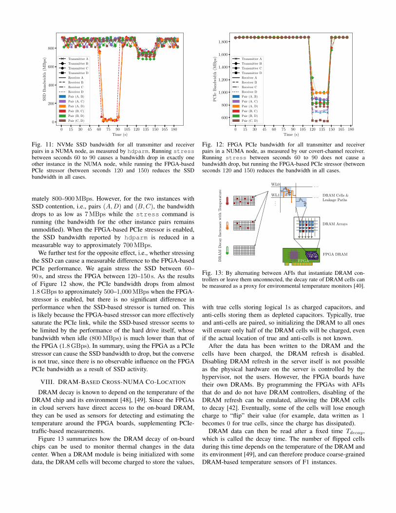
Fig. 11: NVMe SSD bandwidth for all transmitter and receiverpairs in a NUMA node, as measured by hdparm. Running stressbetween seconds 60 to 90 causes a bandwidth drop in exactly oneother instance in the NUMA node, while running the FPGA-basedPCIe stressor (between seconds 120 and 150) reduces the SSDbandwidth in all cases.
mately 800–900MBps. However, for the two instances withSSD contention, i.e., pairs (A,D) and (B,C), the bandwidthdrops to as low as 7MBps while the stress command isrunning (the bandwidth for the other instance pairs remainsunmodified). When the FPGA-based PCIe stressor is enabled,the SSD bandwidth reported by hdparm is reduced in ameasurable way to approximately 700MBps.
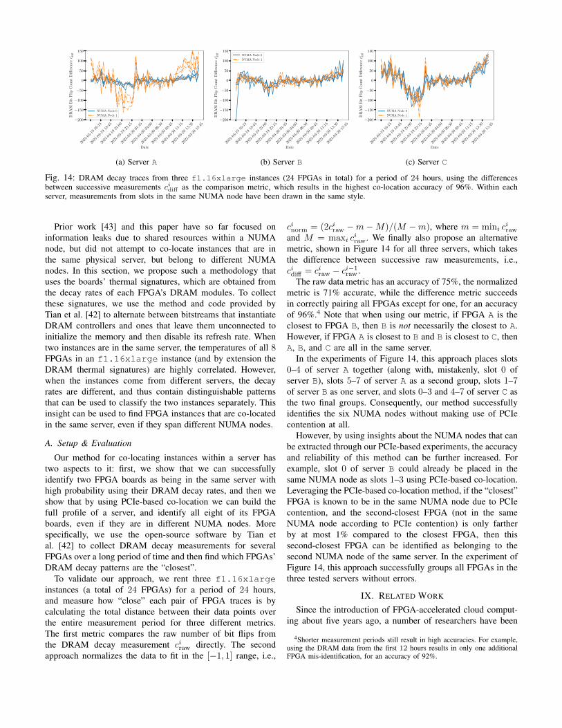
We further test for the opposite effect, i.e., whether stressingthe SSD can cause a measurable difference to the FPGA-basedPCIe performance. We again stress the SSD between 60–90 s, and stress the FPGA between 120–150 s. As the resultsof Figure 12 show, the PCIe bandwidth drops from almost1.8GBps to approximately 500–1,000MBps when the FPGA-stressor is enabled, but there is no significant difference inperformance when the SSD-based stressor is turned on. Thisis likely because the FPGA-based stressor can more effectivelysaturate the PCIe link, while the SSD-based stressor seems tobe limited by the performance of the hard drive itself, whosebandwidth when idle (800MBps) is much lower than that ofthe FPGA (1.8GBps). In summary, using the FPGA as a PCIestressor can cause the SSD bandwidth to drop, but the converseis not true, since there is no observable influence on the FPGAPCIe bandwidth as a result of SSD activity.
VIII. DRAM-BASED CROSS-NUMA CO-LOCATION
DRAM decay is known to depend on the temperature of theDRAM chip and its environment [48], [49]. Since the FPGAsin cloud servers have direct access to the on-board DRAM,they can be used as sensors for detecting and estimating thetemperature around the FPGA boards, supplementing PCIe-traffic-based measurements.
Figure 13 summarizes how the DRAM decay of on-boardchips can be used to monitor thermal changes in the datacenter. When a DRAM module is being initialized with somedata, the DRAM cells will become charged to store the values,
0 15 30 45 60 75 90 105 120 135 150 165 180
Time (s)
600
800
1,000
1,200
1,400
1,600
1,800
PC
IeB
and
wid
th(M
Bp
s) Transmitter A
Transmitter B
Transmitter C
Transmitter D
Receiver A
Receiver B
Receiver C
Receiver D
Pair (A, B)
Pair (A, C)
Pair (A, D)
Pair (B, C)
Pair (B, D)
Pair (C, D)
Fig. 12: FPGA PCIe bandwidth for all transmitter and receiverpairs in a NUMA node, as measured by our covert-channel receiver.Running stress between seconds 60 to 90 does not cause abandwidth drop, but running the FPGA-based PCIe stressor (betweenseconds 120 and 150) reduces the bandwidth in all cases.
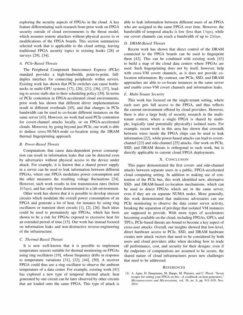
Fig. 13: By alternating between AFIs that instantiate DRAM con-trollers or leave them unconnected, the decay rate of DRAM cells canbe measured as a proxy for environmental temperature monitors [40].
with true cells storing logical 1s as charged capacitors, andanti-cells storing them as depleted capacitors. Typically, trueand anti-cells are paired, so initializing the DRAM to all oneswill ensure only half of the DRAM cells will be charged, evenif the actual location of true and anti-cells is not known.
After the data has been written to the DRAM and thecells have been charged, the DRAM refresh is disabled.Disabling DRAM refresh in the server itself is not possibleas the physical hardware on the server is controlled by thehypervisor, not the users. However, the FPGA boards havetheir own DRAMs. By programming the FPGAs with AFIsthat do and do not have DRAM controllers, disabling of theDRAM refresh can be emulated, allowing the DRAM cellsto decay [42]. Eventually, some of the cells will lose enoughcharge to “flip” their value (for example, data written as 1becomes 0 for true cells, since the charge has dissipated).
DRAM data can then be read after a fixed time Tdecay ,which is called the decay time. The number of flipped cellsduring this time depends on the temperature of the DRAM andits environment [49], and can therefore produce coarse-grainedDRAM-based temperature sensors of F1 instances.
2021
-03-
1916
:15
2021
-03-
1918
:45
2021
-03-
1921
:00
2021
-03-
1923
:15
2021
-03-
2001
:45
2021
-03-
2004
:00
2021
-03-
2006
:30
2021
-03-
2008
:45
2021
-03-
2011
:15
2021
-03-
2013
:30
2021
-03-
2015
:45
Date
−200
−150
−100
−50
0
50
100
150
DR
AM
Bit
Fli
pC
ount
Diff
eren
ceci d
iff
NUMA Node 0
NUMA Node 1
(a) Server A
2021
-03-
1916
:15
2021
-03-
1918
:45
2021
-03-
1921
:00
2021
-03-
1923
:15
2021
-03-
2001
:45
2021
-03-
2004
:00
2021
-03-
2006
:30
2021
-03-
2008
:45
2021
-03-
2011
:15
2021
-03-
2013
:30
2021
-03-
2015
:45
Date
−200
−150
−100
−50
0
50
100
150
DR
AM
Bit
Fli
pC
ount
Diff
eren
ceci d
iff NUMA Node 0
NUMA Node 1
(b) Server B
2021
-03-
1916
:15
2021
-03-
1918
:45
2021
-03-
1921
:00
2021
-03-
1923
:15
2021
-03-
2001
:45
2021
-03-
2004
:00
2021
-03-
2006
:30
2021
-03-
2008
:45
2021
-03-
2011
:15
2021
-03-
2013
:30
2021
-03-
2015
:45
Date
−200
−150
−100
−50
0
50
100
150
DR
AM
Bit
Fli
pC
ount
Diff
eren
ceci d
iff
NUMA Node 0
NUMA Node 1
(c) Server C
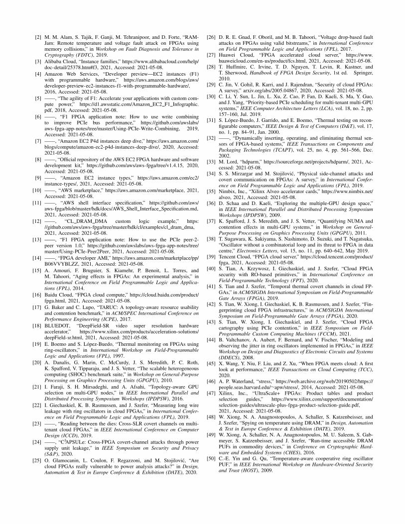
Fig. 14: DRAM decay traces from three f1.16xlarge instances (24 FPGAs in total) for a period of 24 hours, using the differencesbetween successive measurements cidiff as the comparison metric, which results in the highest co-location accuracy of 96%. Within eachserver, measurements from slots in the same NUMA node have been drawn in the same style.
Prior work [43] and this paper have so far focused oninformation leaks due to shared resources within a NUMAnode, but did not attempt to co-locate instances that are inthe same physical server, but belong to different NUMAnodes. In this section, we propose such a methodology thatuses the boards’ thermal signatures, which are obtained fromthe decay rates of each FPGA’s DRAM modules. To collectthese signatures, we use the method and code provided byTian et al. [42] to alternate between bitstreams that instantiateDRAM controllers and ones that leave them unconnected toinitialize the memory and then disable its refresh rate. Whentwo instances are in the same server, the temperatures of all 8FPGAs in an f1.16xlarge instance (and by extension theDRAM thermal signatures) are highly correlated. However,when the instances come from different servers, the decayrates are different, and thus contain distinguishable patternsthat can be used to classify the two instances separately. Thisinsight can be used to find FPGA instances that are co-locatedin the same server, even if they span different NUMA nodes.
A. Setup & Evaluation
Our method for co-locating instances within a server hastwo aspects to it: first, we show that we can successfullyidentify two FPGA boards as being in the same server withhigh probability using their DRAM decay rates, and then weshow that by using PCIe-based co-location we can build thefull profile of a server, and identify all eight of its FPGAboards, even if they are in different NUMA nodes. Morespecifically, we use the open-source software by Tian etal. [42] to collect DRAM decay measurements for severalFPGAs over a long period of time and then find which FPGAs’DRAM decay patterns are the “closest”.
To validate our approach, we rent three f1.16xlargeinstances (a total of 24 FPGAs) for a period of 24 hours,and measure how “close” each pair of FPGA traces is bycalculating the total distance between their data points overthe entire measurement period for three different metrics.The first metric compares the raw number of bit flips fromthe DRAM decay measurement ciraw directly. The secondapproach normalizes the data to fit in the [−1, 1] range, i.e.,
cinorm = (2ciraw −m−M)/(M −m), where m = mini ciraw
and M = maxi ciraw. We finally also propose an alternative
metric, shown in Figure 14 for all three servers, which takesthe difference between successive raw measurements, i.e.,cidiff = ciraw − ci−1
raw .The raw data metric has an accuracy of 75%, the normalized
metric is 71% accurate, while the difference metric succeedsin correctly pairing all FPGAs except for one, for an accuracyof 96%.4 Note that when using our metric, if FPGA A is theclosest to FPGA B, then B is not necessarily the closest to A.However, if FPGA A is closest to B and B is closest to C, thenA, B, and C are all in the same server.
In the experiments of Figure 14, this approach places slots0–4 of server A together (along with, mistakenly, slot 0 ofserver B), slots 5–7 of server A as a second group, slots 1–7of server B as one server, and slots 0–3 and 4–7 of server C asthe two final groups. Consequently, our method successfullyidentifies the six NUMA nodes without making use of PCIecontention at all.
However, by using insights about the NUMA nodes that canbe extracted through our PCIe-based experiments, the accuracyand reliability of this method can be further increased. Forexample, slot 0 of server B could already be placed in thesame NUMA node as slots 1–3 using PCIe-based co-location.Leveraging the PCIe-based co-location method, if the “closest”FPGA is known to be in the same NUMA node due to PCIecontention, and the second-closest FPGA (not in the sameNUMA node according to PCIe contention) is only fartherby at most 1% compared to the closest FPGA, then thissecond-closest FPGA can be identified as belonging to thesecond NUMA node of the same server. In the experiment ofFigure 14, this approach successfully groups all FPGAs in thethree tested servers without errors.
IX. RELATED WORK
Since the introduction of FPGA-accelerated cloud comput-ing about five years ago, a number of researchers have been
4Shorter measurement periods still result in high accuracies. For example,using the DRAM data from the first 12 hours results in only one additionalFPGA mis-identification, for an accuracy of 92%.
exploring the security aspects of FPGAs in the cloud. A keyfeature differentiating such research from prior work on FPGAsecurity outside of cloud environments is the threat model,which assumes remote attackers without physical access to ormodifications of the FPGA boards. This section summarizesselected work that is applicable to the cloud setting, leavingtraditional FPGA security topics to existing books [28] orsurveys [29], [34].
A. PCIe-Based Threats
The Peripheral Component Interconnect Express (PCIe)standard provides a high-bandwidth, point-to-point, full-duplex interface for connecting peripherals within servers.Existing work has shown that PCIe switches can cause bottle-necks in multi-GPU systems [17], [20], [21], [36], [37], lead-ing to severe stalls due to their scheduling policy [30]. In termsof PCIe contention in FPGA-accelerated cloud environments,prior work has shown that different driver implementationsresult in different overheads [45], and that changes in PCIebandwidth can be used to co-locate different instances on thesame server [43]. However, no work had used PCIe contentionfor covert-channel attacks locally, or on FPGA-acceleratedclouds. Moreover, by going beyond just PCIe, our work is ableto deduce cross-NUMA-node co-location using the DRAMthermal fingerprinting approach.
B. Power-Based Threats
Computations that cause data-dependent power consump-tion can result in information leaks that can be detected evenby adversaries without physical access to the device underattack. For example, it is known that a shared power supplyin a server can be used to leak information between differentFPGAs, where one FPGA modulates power consumption andthe other measures the resulting voltage fluctuations [24].However, such work results in low transmission rates (below10 bps), and has only been demonstrated in a lab environment.
Other work has shown that it is possible to develop stressorcircuits which modulate the overall power consumption of anFPGA and generate a lot of heat, for instance by using ringoscillators or transient short circuits [1], [2], [26]. Such ideascould be used to prematurely age FPGAs, which has beenshown to be a risk for FPGAs exposed to excessive heat foran extended period of time [15]. Our work has instead focusedon information leaks and non-destructive reverse-engineeringof the infrastructure.
C. Thermal-Based Threats
It is now well-known that it is possible to implementtemperature sensors suitable for thermal monitoring on FPGAsusing ring oscillators [19], whose frequency drifts in responseto temperature variations [31], [32], [44], [50]. A receiverFPGA could thus use a ring oscillator to observe the ambienttemperature of a data center. For example, existing work [41]has explored a new type of temporal thermal attack: heatgenerated by one circuit can be later observed by other circuitsthat are loaded onto the same FPGA. This type of attack is
able to leak information between different users of an FPGAwho are assigned to the same FPGA over time. However, thebandwidth of temporal attacks is low (less than 1 bps), whileour covert channels can reach a bandwidth of up to 2 kbps.
D. DRAM-Based Threats
Recent work has shown that direct control of the DRAMconnected to the FPGA boards can be used to fingerprintthem [42]. This can be combined with existing work [43]to build a map of the cloud data centers where FPGAs areused. Such fingerprinting does not by itself, however, helpwith cross-VM covert channels, as it does not provide co-location information. By contrast, our PCIe, SSD, and DRAMapproaches are able to co-locate instances in the same serverand enable cross-VM covert channels and information leaks.
E. Multi-Tenant Security
This work has focused on the single-tenant setting, whereeach user gets full access to the FPGA, and thus reflectsthe current environment offered by cloud providers. However,there is also a large body of security research in the multi-tenant context, where a single FPGA is shared by multi-ple, logically (and potentially physically) isolated users. Forexample, recent work in this area has shown that crosstalkbetween wires inside the FPGA chips can be used to leakinformation [22], while power-based attacks can lead to covert-channel [23] and side-channel [25] attacks. Our work on PCIe,SSD, and DRAM threats is orthogonal to such work, but isdirectly applicable to current cloud FPGA deployments.
X. CONCLUSION
This paper demonstrated the first covert- and side-channelattacks between separate users in a public, FPGA-acceleratedcloud computing setting. In addition to making use of con-tention of the PCIe bus, this work identified new, alternativeSSD- and DRAM-based co-location mechanisms, which canbe used to detect FPGAs which are in the same server,even if they are on separate NUMA nodes. More generally,this work demonstrated that malicious adversaries can usePCIe monitoring to observe the data center server activity,breaking the separation of privilege that isolated VM instancesare supposed to provide. With more types of acceleratorsbecoming available on the cloud, including FPGAs, GPUs, andTPUs, PCIe-based threats are bound to become a key aspect ofcross-user attacks. Overall, our insights showed that low-level,direct hardware access to PCIe, SSD, and DRAM hardwarecreates new attack vectors that need to be considered by bothusers and cloud providers alike when deciding how to tradeoff performance, cost, and security for their designs: even ifthe endpoints of computations are assumed to be secure, theshared nature of cloud infrastructures poses new challengesthat need to be addressed.
REFERENCES
[1] A. Agne, H. Hangmann, M. Happe, M. Platzner, and C. Plessl, “Sevenrecipes for setting your FPGA on fire—A cookbook on heat generators,”Microprocessors and Microsystems, vol. 38, no. 8, pp. 911–919, Nov.2014.
[2] M. M. Alam, S. Tajik, F. Ganji, M. Tehranipoor, and D. Forte, “RAM-Jam: Remote temperature and voltage fault attack on FPGAs usingmemory collisions,” in Workshop on Fault Diagnosis and Tolerance inCryptography (FDTC), 2019.
[3] Alibaba Cloud, “Instance families,” https://www.alibabacloud.com/help/doc-detail/25378.htm#f3, 2021, Accessed: 2021-05-08.
[4] Amazon Web Services, “Developer preview—EC2 instances (F1)with programmable hardware,” https://aws.amazon.com/blogs/aws/developer-preview-ec2-instances-f1-with-programmable-hardware/,2016, Accessed: 2021-05-08.
[5] ——, “The agility of F1: Accelerate your applications with custom com-pute power,” https://d1.awsstatic.com/Amazon EC2 F1 Infographic.pdf, 2018, Accessed: 2021-05-08.
[6] ——, “F1 FPGA application note: How to use write combiningto improve PCIe bus performance,” https://github.com/awslabs/aws-fpga-app-notes/tree/master/Using-PCIe-Write-Combining, 2019,Accessed: 2021-05-08.
[7] ——, “Amazon EC2 P4d instances deep dive,” https://aws.amazon.com/blogs/compute/amazon-ec2-p4d-instances-deep-dive/, 2020, Accessed:2021-05-08.
[8] ——, “Official repository of the AWS EC2 FPGA hardware and softwaredevelopment kit,” https://github.com/aws/aws-fpga/tree/v1.4.15, 2020,Accessed: 2021-05-08.
[9] ——, “Amazon EC2 instance types,” https://aws.amazon.com/ec2/instance-types/, 2021, Accessed: 2021-05-08.
[10] ——, “AWS marketplace,” https://aws.amazon.com/marketplace, 2021,Accessed: 2021-05-08.
[11] ——, “AWS shell interface specification,” https://github.com/aws/aws-fpga/blob/master/hdk/docs/AWS Shell Interface Specification.md,2021, Accessed: 2021-05-08.
[12] ——, “CL DRAM DMA custom logic example,” https://github.com/aws/aws-fpga/tree/master/hdk/cl/examples/cl dram dma,2021, Accessed: 2021-05-08.
[13] ——, “F1 FPGA application note: How to use the PCIe peer-2-peer version 1.0,” https://github.com/awslabs/aws-fpga-app-notes/tree/master/Using-PCIe-Peer2Peer, 2021, Accessed: 2021-05-08.
[14] ——, “FPGA developer AMI,” https://aws.amazon.com/marketplace/pp/B06VVYBLZZ, 2021, Accessed: 2021-05-08.
[15] A. Amouri, F. Bruguier, S. Kiamehr, P. Benoit, L. Torres, andM. Tahoori, “Aging effects in FPGAs: An experimental analysis,” inInternational Conference on Field Programmable Logic and Applica-tions (FPL), 2014.
[16] Baidu Cloud, “FPGA cloud compute,” https://cloud.baidu.com/product/fpga.html, 2021, Accessed: 2021-05-08.
[17] G. Baker and C. Lupo, “TARUC: A topology-aware resource usabilityand contention benchmark,” in ACM/SPEC International Conference onPerformance Engineering (ICPE), 2017.
[18] BLUEDOT, “DeepField-SR video super resolution hardwareaccelerator,” https://www.xilinx.com/products/acceleration-solutions/deepField-sr.html, 2021, Accessed: 2021-05-08.
[19] E. Boemo and S. Lopez-Buedo, “Thermal monitoring on FPGAs usingring-oscillators,” in International Workshop on Field-ProgrammableLogic and Applications (FPL), 1997.
[20] A. Danalis, G. Marin, C. McCurdy, J. S. Meredith, P. C. Roth,K. Spafford, V. Tipparaju, and J. S. Vetter, “The scalable heterogeneouscomputing (SHOC) benchmark suite,” in Workshop on General-PurposeProcessing on Graphics Processing Units (GPGPU), 2010.
[21] I. Faraji, S. H. Mirsadeghi, and A. Afsahi, “Topology-aware GPUselection on multi-GPU nodes,” in IEEE International Parallel andDistributed Processing Symposium Workshops (IPDPSW), 2016.
[22] I. Giechaskiel, K. B. Rasmussen, and J. Szefer, “Measuring long wireleakage with ring oscillators in cloud FPGAs,” in International Confer-ence on Field Programmable Logic and Applications (FPL), 2019.
[23] ——, “Reading between the dies: Cross-SLR covert channels on multi-tenant cloud FPGAs,” in IEEE International Conference on ComputerDesign (ICCD), 2019.
[24] ——, “C3APSULe: Cross-FPGA covert-channel attacks through powersupply unit leakage,” in IEEE Symposium on Security and Privacy(S&P), 2020.
[25] O. Glamocanin, L. Coulon, F. Regazzoni, and M. Stojilovic, “Arecloud FPGAs really vulnerable to power analysis attacks?” in Design,Automation & Test in Europe Conference & Exhibition (DATE), 2020.
[26] D. R. E. Gnad, F. Oboril, and M. B. Tahoori, “Voltage drop-based faultattacks on FPGAs using valid bitstreams,” in International Conferenceon Field Programmable Logic and Applications (FPL), 2017.
[27] Huawei Cloud, “FPGA accelerated cloud server,” https://www.huaweicloud.com/en-us/product/fcs.html, 2021, Accessed: 2021-05-08.
[28] T. Huffmire, C. Irvine, T. D. Nguyen, T. Levin, R. Kastner, andT. Sherwood, Handbook of FPGA Design Security, 1st ed. Springer,2010.
[29] C. Jin, V. Gohil, R. Karri, and J. Rajendran, “Security of cloud FPGAs:A survey,” arxiv.org/abs/2005.04867, 2020, Accessed: 2021-05-08.
[30] C. Li, Y. Sun, L. Jin, L. Xu, Z. Cao, P. Fan, D. Kaeli, S. Ma, Y. Guo,and J. Yang, “Priority-based PCIe scheduling for multi-tenant multi-GPUsystems,” IEEE Computer Architecture Letters (LCA), vol. 18, no. 2, pp.157–160, Jul. 2019.
[31] S. Lopez-Buedo, J. Garrido, and E. Boemo, “Thermal testing on recon-figurable computers,” IEEE Design & Test of Computers (D&T), vol. 17,no. 1, pp. 84–91, Jan. 2000.
[32] ——, “Dynamically inserting, operating, and eliminating thermal sen-sors of FPGA-based systems,” IEEE Transactions on Components andPackaging Technologies (TCAPT), vol. 25, no. 4, pp. 561–566, Dec.2002.
[33] M. Lord, “hdparm,” https://sourceforge.net/projects/hdparm/, 2021, Ac-cessed: 2021-05-08.
[34] S. S. Mirzargar and M. Stojilovic, “Physical side-channel attacks andcovert communication on FPGAs: A survey,” in International Confer-ence on Field Programmable Logic and Applications (FPL), 2019.
[35] Nimbix, Inc., “Xilinx Alveo accelerator cards,” https://www.nimbix.net/alveo, 2021, Accessed: 2021-05-08.
[36] D. Schaa and D. Kaeli, “Exploring the multiple-GPU design space,”in IEEE International Parallel and Distributed Processing SymposiumWorkshops (IPDPSW), 2009.
[37] K. Spafford, J. S. Meredith, and J. S. Vetter, “Quantifying NUMA andcontention effects in multi-GPU systems,” in Workshop on General-Purpose Processing on Graphics Processing Units (GPGPU), 2011.
[38] T. Sugawara, K. Sakiyama, S. Nashimoto, D. Suzuki, and T. Nagatsuka,“Oscillator without a combinatorial loop and its threat to FPGA in datacentre,” Electronics Letters, vol. 15, no. 11, pp. 640–642, May 2019.
[39] Tencent Cloud, “FPGA cloud server,” https://cloud.tencent.com/product/fpga, 2021, Accessed: 2021-05-08.
[40] S. Tian, A. Krzywosz, I. Giechaskiel, and J. Szefer, “Cloud FPGAsecurity with RO-based primitives,” in International Conference onField-Programmable Technology (FPT), 2020.
[41] S. Tian and J. Szefer, “Temporal thermal covert channels in cloud FP-GAs,” in ACM/SIGDA International Symposium on Field-ProgrammableGate Arrays (FPGA), 2019.
[42] S. Tian, W. Xiong, I. Giechaskiel, K. B. Rasmussen, and J. Szefer, “Fin-gerprinting cloud FPGA infrastructures,” in ACM/SIGDA InternationalSymposium on Field-Programmable Gate Arrays (FPGA), 2020.
[43] S. Tian, W. Xiong, I. Giechaskiel, and J. Szefer, “Cloud FPGAcartography using PCIe contention,” in IEEE Symposium on Field-Programmable Custom Computing Machines (FCCM), 2021.
[44] B. Valtchanov, A. Aubert, F. Bernard, and V. Fischer, “Modeling andobserving the jitter in ring oscillators implemented in FPGAs,” in IEEEWorkshop on Design and Diagnostics of Electronic Circuits and Systems(DDECS), 2008.
[45] X. Wang, Y. Niu, F. Liu, and Z. Xu, “When FPGA meets cloud: A firstlook at performance,” IEEE Transactions on Cloud Computing (TCC),2020.
[46] A. P. Waterland, “stress,” https://web.archive.org/web/20190502/https://people.seas.harvard.edu/∼apw/stress/, 2014, Accessed: 2021-05-08.
[47] Xilinx, Inc., “UltraScale+ FPGAs: Product tables and productselection guides,” https://www.xilinx.com/support/documentation/selection-guides/ultrascale-plus-fpga-product-selection-guide.pdf,2021, Accessed: 2021-05-08.
[48] W. Xiong, N. A. Anagnostopoulos, A. Schaller, S. Katzenbeisser, andJ. Szefer, “Spying on temperature using DRAM,” in Design, Automation& Test in Europe Conference & Exhibition (DATE), 2019.
[49] W. Xiong, A. Schaller, N. A. Anagnostopoulos, M. U. Saleem, S. Gab-meyer, S. Katzenbeisser, and J. Szefer, “Run-time accessible DRAMPUFs in commodity devices,” in Conference on Cryptographic Hard-ware and Embedded Systems (CHES), 2016.
[50] C.-E. Yin and G. Qu, “Temperature-aware cooperative ring oscillatorPUF,” in IEEE International Workshop on Hardware-Oriented Securityand Trust (HOST), 2009.


![CICADA - USENIX · 1 vm 2 vm 3 vm 4 vm 5vm 6 vm 7 vm 8 vm 9 vm 2 vm 3 vm 4 vm 5 vm 6 vm 7 vm 8 vm 9 vm 1 rigid application (similar to VOC [1]) vm 1 vm 2 vm 3 vm 4 vm 5vm 6 vm 7 vm](https://img.pdfslide.us/doc/110x75/5f3ade2be7477529602b0cb3/cicada-usenix-1-vm-2-vm-3-vm-4-vm-5vm-6-vm-7-vm-8-vm-9-vm-2-vm-3-vm-4-vm-5-vm.jpg)