Embed Size (px)
Citation preview
DECK DESIGN GUIDE • 1
CIT
Y O
F P
OR
TLA
ND
, O
REG
ON
- B
UR
EAU
OF
DEV
ELO
PM
ENT
SER
VIC
ES19
00
SW
4th
Ave
nu
e, P
ort
lan
d, O
reg
on
97
20
1 •
50
3-8
23
-73
00
• w
ww
.po
rtla
nd
ore
go
n.g
ov/
bd
s3a
Rim joist
GradeJoist
Ledger board
Ledger boardattachment
Footing
Post to beamconnection
Built-up beam
Guard
Deck Design GuideOne and Two Family Residential DwellingsThe Bureau of Development Services (BDS) is providing this informa-tion to help you design your deck, obtain a building permit and pass inspections. The standards and details in this Guide will help you determine how large the footings, beams, joists, posts, and ledgers need to be; how to build lateral bracing, stairs, and railings; and how to fasten all of the pieces together. This Guide does not take into ac-count conditions which may affect your deck design such as drainage conditions, slope conditions, or decks supporting loads in excess of the standard uniform loads. Depending on your specifi c situation, you may need to hire a licensed architect or structural engineer prior to approval.
You may include all, or part of the pre-approved design standards and details in this guide with your building permit plans for decks that are:
• For one- and two-family dwellings
• Single-span
• All on one level
• Not supporting a hot tub or spa
• Not attached to house overhangs, bay windows, brick, stone or concrete block
• Not more than 10 feet above the ground
• Not bearing on ground with a slope greater than 2 feet horizontal for every 1 foot vertical
CONTENTS
Do I Need A Permit? .............................. 2
What Plans Do I Need? ......................... 2
General Notes ....................................... 3
Footings, Beams, Joists, and Posts ......... 4
The Ledger Board ................................. 7
Freestanding Decks ............................ 11
Lateral Support of Decks ..................... 11
Framing Connections .......................... 12
Footings ............................................. 13
Guardrails .......................................... 13
Stairs ................................................. 18
Chimneys/Bay Windows ...................... 20
Deck Framing Plan .............................. 21
Helpful Information ............................ 22
2 • DECK DESIGN GUIDE
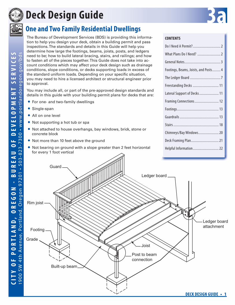
IntroductionDo I Need A Permit For My Deck?A building permit is required for all decks that are more than 30 inches above the ground at any point. See Brochure 3 , Fences, Decks and Outdoor Projects.
Setbacks and Other Regulations?For information on setbacks (how close a deck is to a property line) and other regulations that may apply to your deck project, even when a building permit is not required, see Brochure 3. Call Planning and Zoning at 503-823-7526 to fi nd out what zoning requirements apply to your specifi c property.
How Do I Get A Building Permit?See BDS handout, Brochure 1, Guide to Permits and Inspections. This handout describes the building permit process from application to fi nal inspection.
What Plans Do I Need?You may draw all your own plans and details without using this Guide, or you may use the pre-approved standards and details in this Guide to supplement your plans. Refer to Brochure 6, What Plans Do I Need for a Building Permit?
for descriptions and examples of the plans needed to obtain a building permit for a typical residential construction project. Since a deck can be a relatively simple project, you will only be required to provide the plans listed below if you use this Guide: • Site Plan - You will need to draw a site plan. The Site Plan must show the
property lines, outlines of all existing and proposed buildings, paved areas and decks on the lot, and the distances from your proposed deck to the nearest property lines. See Brochure 6 for Site Plan requirements and a sample Site Plan.
• Elevation View - You will also need to draw an Elevation View, which is a front or side view of your house and the proposed deck and the level of the ground adjacent to the deck (see Brochure 6).
• Framing and Foundation Plan - You can draw your own Framing and Foun-dation Plans (see Brochure 6) or you can complete the Worksheet and Typi-cal Deck Plan at the end of this Guide.
• Cross Section and Details - You can draw your own Cross Section and Details (see Brochure 6) or you can use the details in this Guide. Your plans must include details of the following parts of your deck:
• Ledger board attachment
• Joist-to-beam connection
• Rim joist connection
• Post-to-beam connection
• Lateral support method
• Guardrail height and openings
• Guardrail post attachment
• Stair and stair handrail details
• Post-to-footing connection
DECK DESIGN GUIDE • 3
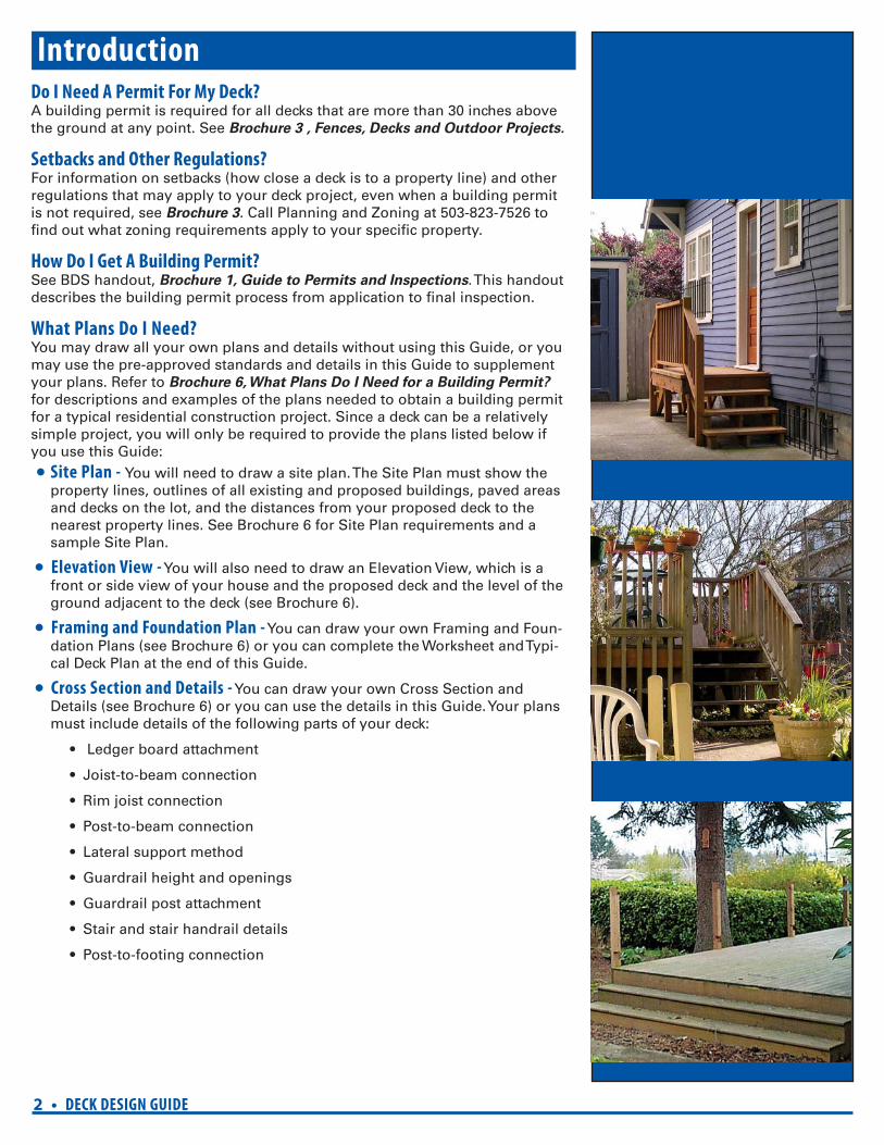
General Notes 1. All lumber shall be grade #2 Douglas-Fir, Hem-Fir, or better and shall be
pressure treated (to resist insect and dry rot) in accordance with American Wood-Preservers’ Association Standards (Category). Deck surface and trim material of redwood, cedar, or other wood with a natural resistance to de-cay does not require pressure treatment. The level of treatment depends on the use as follows:
a. Decking material, railings, joists, and beams must be treated to a Cat-egory UC3B (or must be other wood with a natural resistance to decay).
b. Posts and other woods located on, in, or in contact with the ground must be a Category UC4B.
c. Any wood less than six inches above the ground or in contact with con-crete must be a Category UC4A.
The level of preservative treatment is noted on the tags on the ends of the wood members. Remember, any time you make a cut, treat the cut end of the wood with a paint-on preservative. Cut ends expose the inner untreated wood to potential moisture and insect damage.
Hardwood and plastic or composite decking products may be substituted for conventional wood decking, but installation and span lengths of the substituted material must be in strict conformance with the product listing and the manufacturer’s installation instructions. Copies of the manufac-turer’s installation instructions must be submitted with the building permit application.
2. All nails shall be common or box galvanized. It is recommended that com-mon nails be used. They have a thicker shank and are stronger than box nails.
3. New pressure treatment methods use chemicals that will prematurely cor-rode standard fasteners, hardware, and fl ashing when in contact with pres-sure treated lumber; and as a result, fastener and hardware requirements have changed. Note the following:
a. All screws and nails shall be hot-dipped galvanized or stainless steel.
b. All hardware (bolts, nuts and washers, joist hangers, mechanical fasten-ers, holdowns, tie plates cast-in-place post anchors, etc.) shall be gal-vanized with 1.85 oz/sf of zinc (G-185 coating) or shall be stainless steel. Look for products such as “Zmax” from Simpson Strong-Tie or “Triple Zinc” from USP.
4. All decking material shall be 2x4, 2x6, or fi ve quarter (5/4”) boards. Attach decking to each joist with two 10d nails or two #8 screws. Decking may be placed from an angle perpendicular to the joists to an angle of 45 degrees to the joists. Decking must have a span length such that each board bears on a minimum of two joists.
5. Headers over existing doors, windows or openings greater than six feet in width that are located below a deck that will be attached to the house must be checked to verify that those headers can support the additional load added by the deck.
6. The bottom of all footings for decks that are attached to a house are to be placed a minimum of 18 inches below the surface of the fi nished grade and must bear on fi rm, undisturbed native soil. The bottom of footings for free-standing decks may be at any depth on undisturbed native soil. Footings adjacent to the top of a retaining wall must be set back from the wall a dis-tance equal to the height of the wall, or be extend below grade an amount equal to the height of the retaining wall.
4 • DECK DESIGN GUIDE
2'-0" max.
Joist "A"Beam "B"
Optional overhang
Blocking
Footing "D"
Post "C"
(Min. span = 6'-0" with overhang)overhangJoist span
Joist span
Optional overhang
2'-0" max.(Min. span = 6'-0" with overhang)overhang
2'-0" max.
Blocking
B
C
D
A
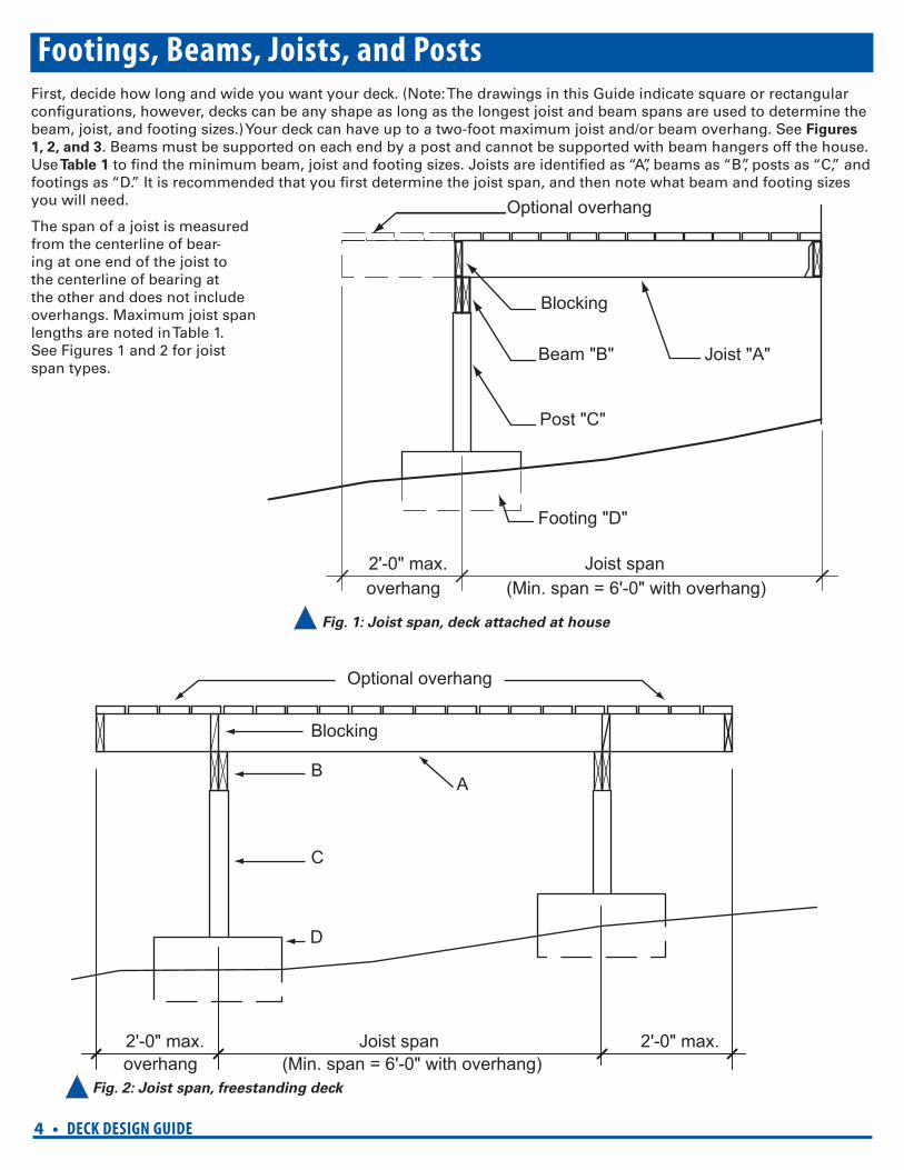
Footings, Beams, Joists, and PostsFirst, decide how long and wide you want your deck. (Note: The drawings in this Guide indicate square or rectangular confi gurations, however, decks can be any shape as long as the longest joist and beam spans are used to determine the beam, joist, and footing sizes.) Your deck can have up to a two-foot maximum joist and/or beam overhang. See Figures
1, 2, and 3. Beams must be supported on each end by a post and cannot be supported with beam hangers off the house. Use Table 1 to fi nd the minimum beam, joist and footing sizes. Joists are identifi ed as “A”, beams as “B”, posts as “C,” and footings as “D.” It is recommended that you fi rst determine the joist span, and then note what beam and footing sizes you will need.
The span of a joist is measured from the centerline of bear-ing at one end of the joist to the centerline of bearing at the other and does not include overhangs. Maximum joist span lengths are noted in Table 1. See Figures 1 and 2 for joist span types.
Fig. 1: Joist span, deck attached at house
Fig. 2: Joist span, freestanding deck
DECK DESIGN GUIDE • 5
Beam span
Optional overhang
2'-0" max. Beam span
6" min
Beam splices atinterior postlocations only
B
C
D
A
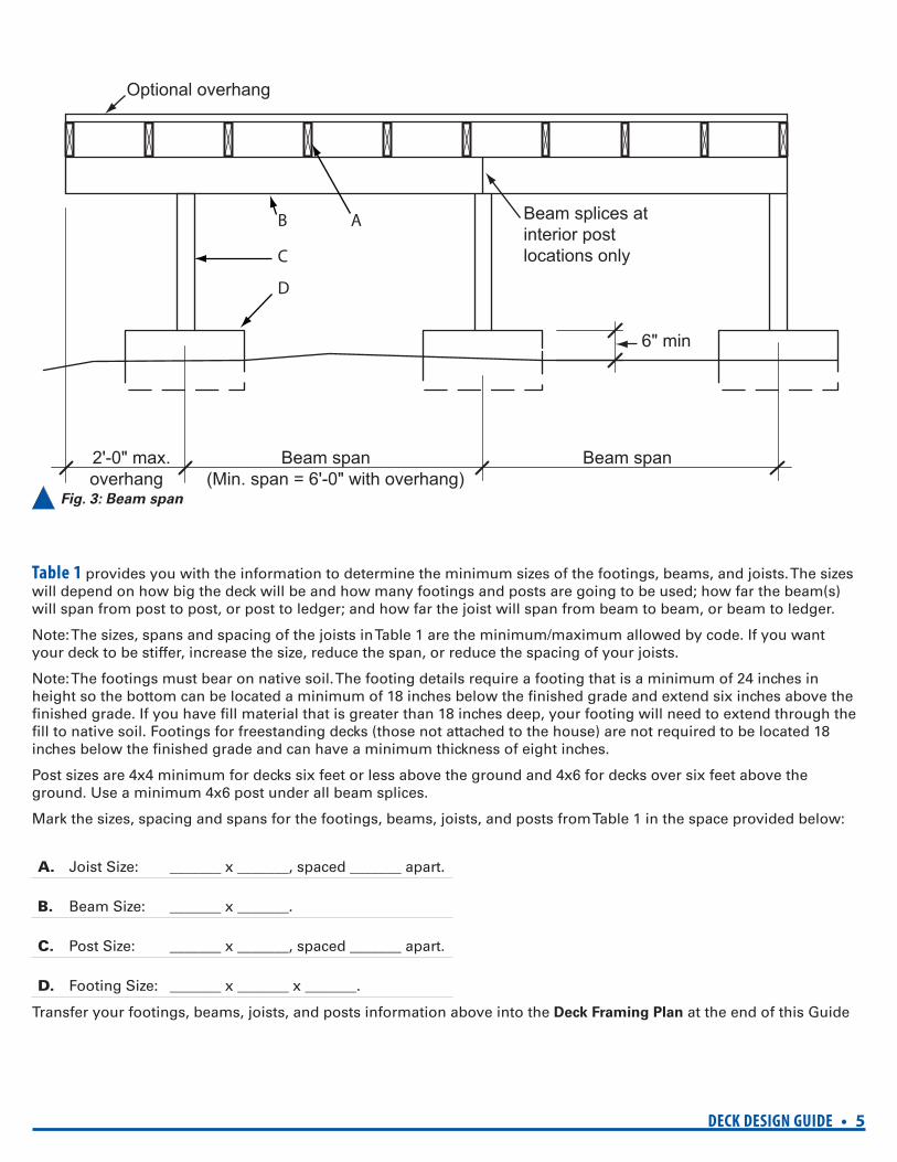
(Min. span = 6'-0" with overhang)overhang Fig. 3: Beam span
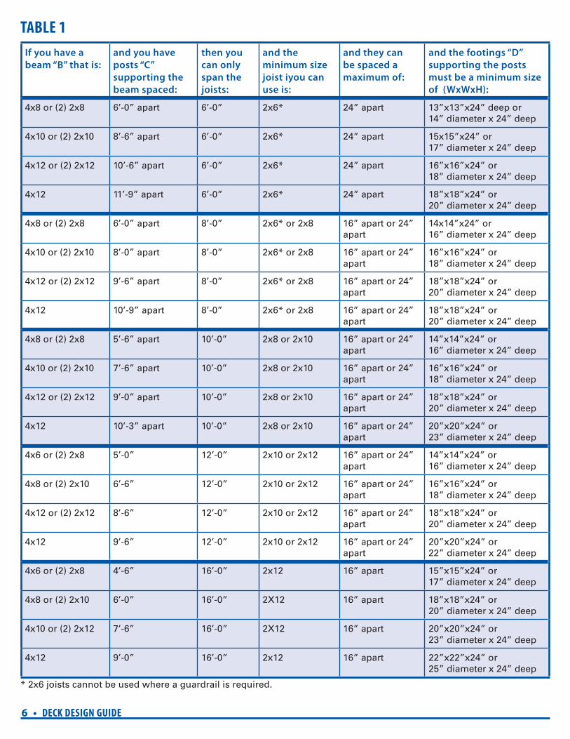
Table 1 provides you with the information to determine the minimum sizes of the footings, beams, and joists. The sizes will depend on how big the deck will be and how many footings and posts are going to be used; how far the beam(s) will span from post to post, or post to ledger; and how far the joist will span from beam to beam, or beam to ledger.
Note: The sizes, spans and spacing of the joists in Table 1 are the minimum/maximum allowed by code. If you want your deck to be stiffer, increase the size, reduce the span, or reduce the spacing of your joists.
Note: The footings must bear on native soil. The footing details require a footing that is a minimum of 24 inches in height so the bottom can be located a minimum of 18 inches below the fi nished grade and extend six inches above the fi nished grade. If you have fi ll material that is greater than 18 inches deep, your footing will need to extend through the fi ll to native soil. Footings for freestanding decks (those not attached to the house) are not required to be located 18 inches below the fi nished grade and can have a minimum thickness of eight inches.
Post sizes are 4x4 minimum for decks six feet or less above the ground and 4x6 for decks over six feet above the ground. Use a minimum 4x6 post under all beam splices.
Mark the sizes, spacing and spans for the footings, beams, joists, and posts from Table 1 in the space provided below:
A. Joist Size: _______ x _______, spaced _______ apart.
B. Beam Size: _______ x _______.
C. Post Size: _______ x _______, spaced _______ apart.
D. Footing Size: _______ x _______ x _______.
Transfer your footings, beams, joists, and posts information above into the Deck Framing Plan at the end of this Guide
6 • DECK DESIGN GUIDE
TABLE 1
If you have a
beam “B” that is:
and you have
posts “C”
supporting the
beam spaced:
then you
can only
span the
joists:
and the
minimum size
joist iyou can
use is:
and they can
be spaced a
maximum of:
and the footings “D”
supporting the posts
must be a minimum size
of (WxWxH):
4x8 or (2) 2x8 6’-0” apart 6’-0” 2x6* 24” apart 13”x13”x24” deep or 14” diameter x 24” deep
4x10 or (2) 2x10 8’-6” apart 6’-0” 2x6* 24” apart 15x15”x24” or 17” diameter x 24” deep
4x12 or (2) 2x12 10’-6” apart 6’-0” 2x6* 24” apart 16”x16”x24” or 18” diameter x 24” deep
4x12 11’-9” apart 6’-0” 2x6* 24” apart 18”x18”x24” or 20” diameter x 24” deep
4x8 or (2) 2x8 6’-0” apart 8’-0” 2x6* or 2x8 16” apart or 24” apart
14x14”x24” or 16” diameter x 24” deep
4x10 or (2) 2x10 8’-0” apart 8’-0” 2x6* or 2x8 16” apart or 24” apart
16”x16”x24” or 18” diameter x 24” deep
4x12 or (2) 2x12 9’-6” apart 8’-0” 2x6* or 2x8 16” apart or 24” apart
18”x18”x24” or 20” diameter x 24” deep
4x12 10’-9” apart 8’-0” 2x6* or 2x8 16” apart or 24” apart
18”x18”x24” or 20” diameter x 24” deep
4x8 or (2) 2x8 5’-6” apart 10’-0” 2x8 or 2x10 16” apart or 24” apart
14”x14”x24” or 16” diameter x 24” deep
4x10 or (2) 2x10 7’-6” apart 10’-0” 2x8 or 2x10 16” apart or 24” apart
16”x16”x24” or 18” diameter x 24” deep
4x12 or (2) 2x12 9’-0” apart 10’-0” 2x8 or 2x10 16” apart or 24” apart
18”x18”x24” or 20” diameter x 24” deep
4x12 10’-3” apart 10’-0” 2x8 or 2x10 16” apart or 24” apart
20”x20”x24” or 23” diameter x 24” deep
4x6 or (2) 2x8 5’-0” 12’-0” 2x10 or 2x12 16” apart or 24” apart
14”x14”x24” or 16” diameter x 24” deep
4x8 or (2) 2x10 6’-6” 12’-0” 2x10 or 2x12 16” apart or 24” apart
16”x16”x24” or 18” diameter x 24” deep
4x12 or (2) 2x12 8’-6” 12’-0” 2x10 or 2x12 16” apart or 24” apart
18”x18”x24” or 20” diameter x 24” deep
4x12 9’-6” 12’-0” 2x10 or 2x12 16” apart or 24” apart
20”x20”x24” or 22” diameter x 24” deep
4x6 or (2) 2x8 4’-6” 16’-0” 2x12 16” apart 15”x15”x24” or 17” diameter x 24” deep
4x8 or (2) 2x10 6’-0” 16’-0” 2X12 16” apart 18”x18”x24” or 20” diameter x 24” deep
4x10 or (2) 2x12 7’-6” 16’-0” 2X12 16” apart 20”x20”x24” or 23” diameter x 24” deep
4x12 9’-0” 16’-0” 2x12 16” apart 22”x22”x24” or 25” diameter x 24” deep
* 2x6 joists cannot be used where a guardrail is required.
DECK DESIGN GUIDE • 7
First layer flashing behind building and ledger board, and over siding Second layer “Z” flashing over top and down face of ledger board
Exterior wall sheathing(15/32" max sheathing)Existing wall
Decking over deck joistExisting 2X
rim (band)
2X floor joist
Existing wall framingor concrete wall(shown dashed)
2X ledger, same sizeas deck joist
Joist hanger LUS26(or equal) min.
1/2" lag screws or(2) #14X4" wood screws or(2) 1/4"X4" Simpson SDS screws (or equal) at spacing “S”
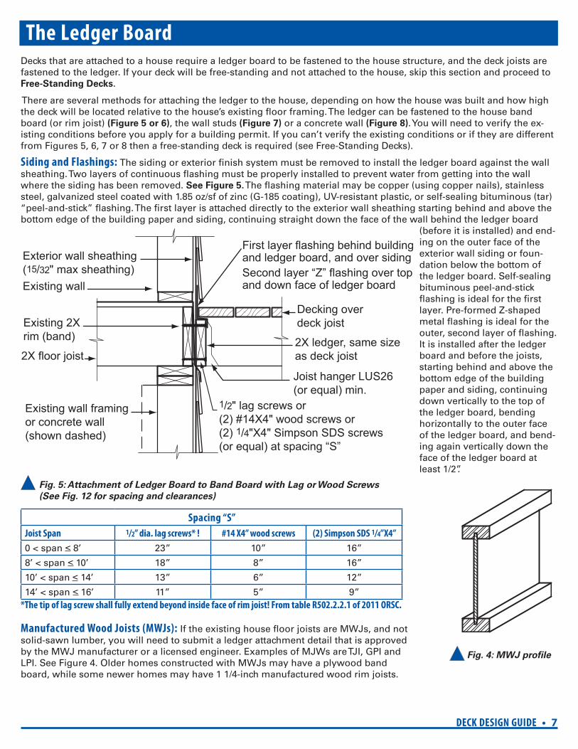
Fig. 4: MWJ profi le
The Ledger BoardDecks that are attached to a house require a ledger board to be fastened to the house structure, and the deck joists are fastened to the ledger. If your deck will be free-standing and not attached to the house, skip this section and proceed to Free-Standing Decks.
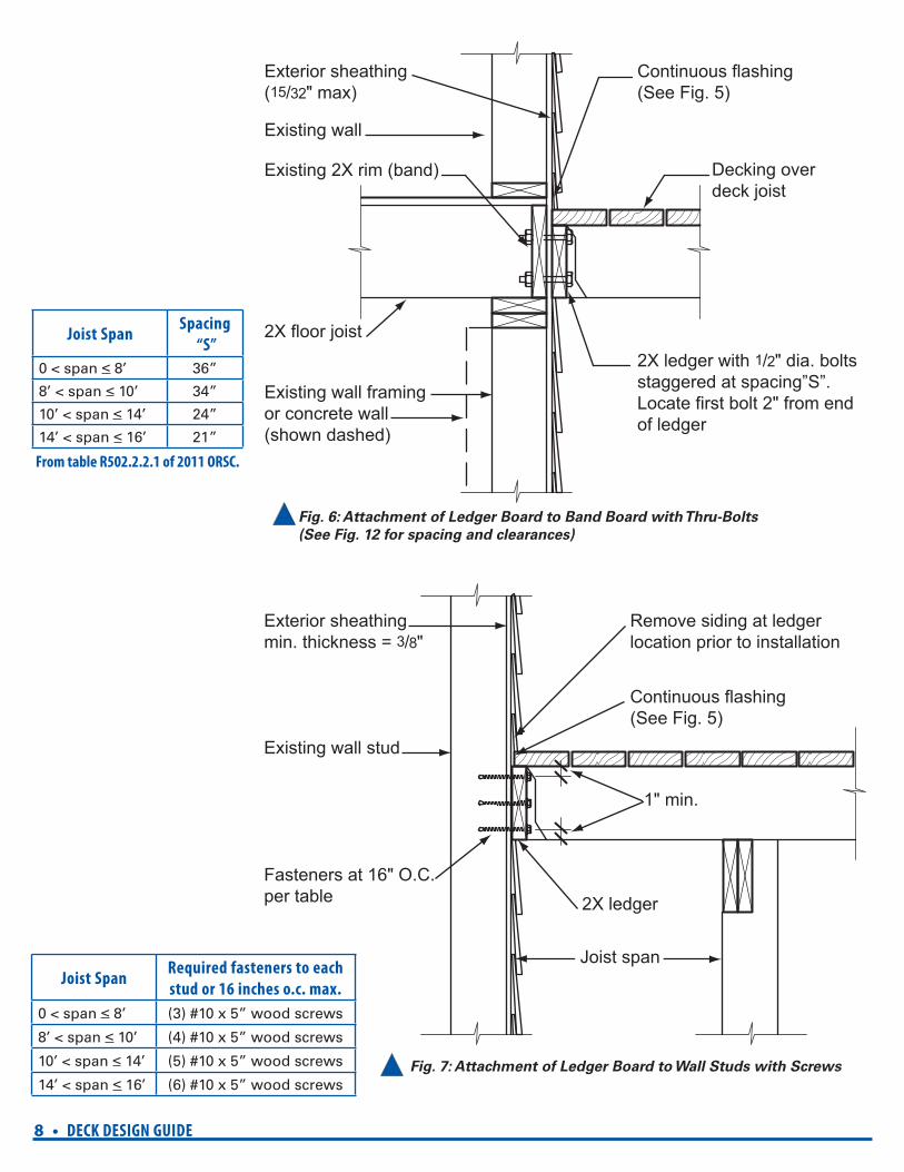
There are several methods for attaching the ledger to the house, depending on how the house was built and how high the deck will be located relative to the house’s existing fl oor framing. The ledger can be fastened to the house band board (or rim joist) (Figure 5 or 6), the wall studs (Figure 7) or a concrete wall (Figure 8). You will need to verify the ex-isting conditions before you apply for a building permit. If you can’t verify the existing conditions or if they are different from Figures 5, 6, 7 or 8 then a free-standing deck is required (see Free-Standing Decks).
Siding and Flashings: The siding or exterior fi nish system must be removed to install the ledger board against the wall sheathing. Two layers of continuous fl ashing must be properly installed to prevent water from getting into the wall where the siding has been removed. See Figure 5. The fl ashing material may be copper (using copper nails), stainless steel, galvanized steel coated with 1.85 oz/sf of zinc (G-185 coating), UV-resistant plastic, or self-sealing bituminous (tar) “peel-and-stick” fl ashing. The fi rst layer is attached directly to the exterior wall sheathing starting behind and above the bottom edge of the building paper and siding, continuing straight down the face of the wall behind the ledger board
(before it is installed) and end-ing on the outer face of the exterior wall siding or foun-dation below the bottom of the ledger board. Self-sealing bituminous peel-and-stick fl ashing is ideal for the fi rst layer. Pre-formed Z-shaped metal fl ashing is ideal for the outer, second layer of fl ashing. It is installed after the ledger board and before the joists, starting behind and above the bottom edge of the building paper and siding, continuing down vertically to the top of the ledger board, bending horizontally to the outer face of the ledger board, and bend-ing again vertically down the face of the ledger board at least 1/2”.
Fig. 5: Attachment of Ledger Board to Band Board with Lag or Wood Screws
(See Fig. 12 for spacing and clearances)
Spacing “S”
Joist Span 1/2” dia. lag screws* ! #14 X4” wood screws (2) Simpson SDS 1/4”X4”
0 < span < 8’ 23” 10” 16”
8’ < span < 10’ 18” 8” 16”
10’ < span < 14’ 13” 6” 12”
14’ < span < 16’ 11” 5” 9”*The tip of lag screw shall fully extend beyond inside face of rim joist! From table R502.2.2.1 of 2011 ORSC.
Manufactured Wood Joists (MWJs): If the existing house fl oor joists are MWJs, and not solid-sawn lumber, you will need to submit a ledger attachment detail that is approved by the MWJ manufacturer or a licensed engineer. Examples of MJWs are TJI, GPI and LPI. See Figure 4. Older homes constructed with MWJs may have a plywood band board, while some newer homes may have 1 1/4-inch manufactured wood rim joists.
8 • DECK DESIGN GUIDE
Exterior sheathing(15/32" max)
Existing wall framing or concrete wall(shown dashed)
2X floor joist
Existing 2X rim (band)
Existing wall
Continuous flashing (See Fig. 5)
2X ledger with 1/2" dia. boltsstaggered at spacing”S”. Locate first bolt 2" from endof ledger
Decking overdeck joist
Continuous flashing(See Fig. 5)
Existing wall stud
Fasteners at 16" O.C.per table
1" min.
Remove siding at ledgerlocation prior to installation
2X ledger
Exterior sheathingmin. thickness = 3/8"
Joist span
Joist SpanSpacing
“S”
0 < span < 8’ 36”
8’ < span < 10’ 34”
10’ < span < 14’ 24”
14’ < span < 16’ 21”
Fig. 6: Attachment of Ledger Board to Band Board with Thru-Bolts
(See Fig. 12 for spacing and clearances)
Joist SpanRequired fasteners to each
stud or 16 inches o.c. max.
0 < span < 8’ (3) #10 x 5” wood screws
8’ < span < 10’ (4) #10 x 5” wood screws
10’ < span < 14’ (5) #10 x 5” wood screws
14’ < span < 16’ (6) #10 x 5” wood screws Fig. 7: Attachment of Ledger Board to Wall Studs with Screws
From table R502.2.2.1 of 2011 ORSC.
DECK DESIGN GUIDE • 9
Concretewall
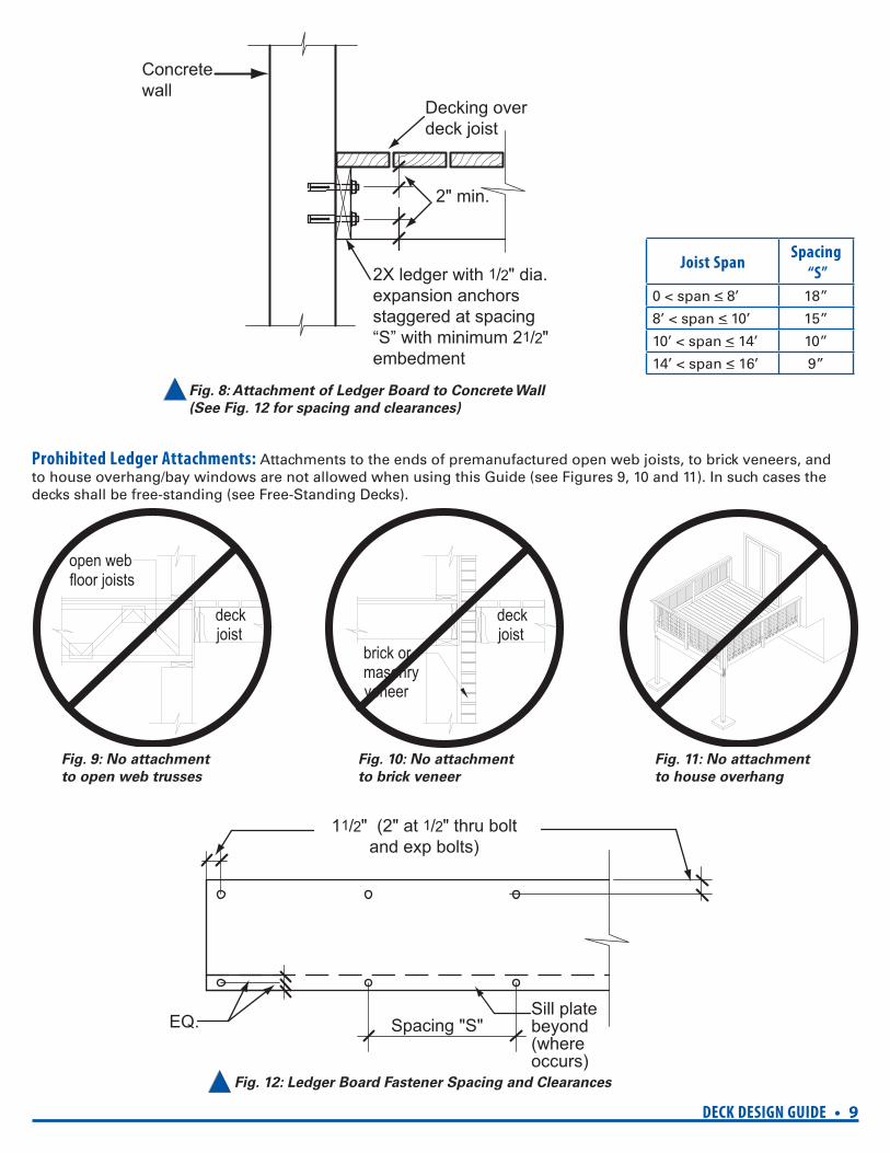
2X ledger with 1/2" dia.expansion anchorsstaggered at spacing“S” with minimum 21/2"embedment
Decking overdeck joist
2" min.
open web floor joists
deck joist
brick or masonry veneer
deck joist
Fig. 9: No attachment
to open web trusses
Fig. 10: No attachment
to brick veneer
Fig. 11: No attachment
to house overhang
Sill platebeyond(whereoccurs)
11/2" (2" at 1/2" thru boltand exp bolts)
EQ. Spacing "S"
Joist SpanSpacing
“S”
0 < span < 8’ 18”
8’ < span < 10’ 15”
10’ < span < 14’ 10”
14’ < span < 16’ 9”
Fig. 8: Attachment of Ledger Board to Concrete Wall
(See Fig. 12 for spacing and clearances)
Prohibited Ledger Attachments: Attachments to the ends of premanufactured open web joists, to brick veneers, and to house overhang/bay windows are not allowed when using this Guide (see Figures 9, 10 and 11). In such cases the decks shall be free-standing (see Free-Standing Decks).
Fig. 12: Ledger Board Fastener Spacing and Clearances
10 • DECK DESIGN GUIDE
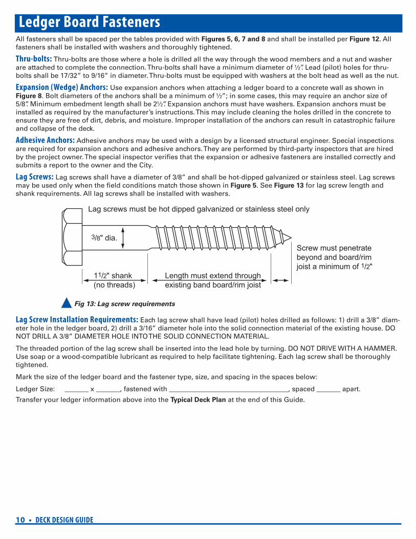
11/2" shank(no threads)
3/8" dia.
Length must extend throughexisting band board/rim joist
Screw must penetratebeyond and board/rimjoist a minimum of 1/2"
Lag screws must be hot dipped galvanized or stainless steel only
Ledger Board FastenersAll fasteners shall be spaced per the tables provided with Figures 5, 6, 7 and 8 and shall be installed per Figure 12. All fasteners shall be installed with washers and thoroughly tightened.
Thru-bolts: Thru-bolts are those where a hole is drilled all the way through the wood members and a nut and washer are attached to complete the connection. Thru-bolts shall have a minimum diameter of ½”. Lead (pilot) holes for thru-bolts shall be 17/32” to 9/16” in diameter. Thru-bolts must be equipped with washers at the bolt head as well as the nut.
Expansion (Wedge) Anchors: Use expansion anchors when attaching a ledger board to a concrete wall as shown in Figure 8. Bolt diameters of the anchors shall be a minimum of ½”; in some cases, this may require an anchor size of 5/8”. Minimum embedment length shall be 2½”. Expansion anchors must have washers. Expansion anchors must be installed as required by the manufacturer’s instructions. This may include cleaning the holes drilled in the concrete to ensure they are free of dirt, debris, and moisture. Improper installation of the anchors can result in catastrophic failure and collapse of the deck.
Adhesive Anchors: Adhesive anchors may be used with a design by a licensed structural engineer. Special inspections are required for expansion anchors and adhesive anchors. They are performed by third-party inspectors that are hired by the project owner. The special inspector verifi es that the expansion or adhesive fasteners are installed correctly and submits a report to the owner and the City.
Lag Screws: Lag screws shall have a diameter of 3/8” and shall be hot-dipped galvanized or stainless steel. Lag screws may be used only when the fi eld conditions match those shown in Figure 5. See Figure 13 for lag screw length and shank requirements. All lag screws shall be installed with washers.
Fig 13: Lag screw requirements
Lag Screw Installation Requirements: Each lag screw shall have lead (pilot) holes drilled as follows: 1) drill a 3/8” diam-eter hole in the ledger board, 2) drill a 3/16” diameter hole into the solid connection material of the existing house. DO NOT DRILL A 3/8” DIAMETER HOLE INTO THE SOLID CONNECTION MATERIAL.
The threaded portion of the lag screw shall be inserted into the lead hole by turning. DO NOT DRIVE WITH A HAMMER. Use soap or a wood-compatible lubricant as required to help facilitate tightening. Each lag screw shall be thoroughly tightened.
Mark the size of the ledger board and the fastener type, size, and spacing in the spaces below:
Ledger Size: _______ x _______, fastened with ___________________________________, spaced _______ apart.
Transfer your ledger information above into the Typical Deck Plan at the end of this Guide.
DECK DESIGN GUIDE • 11
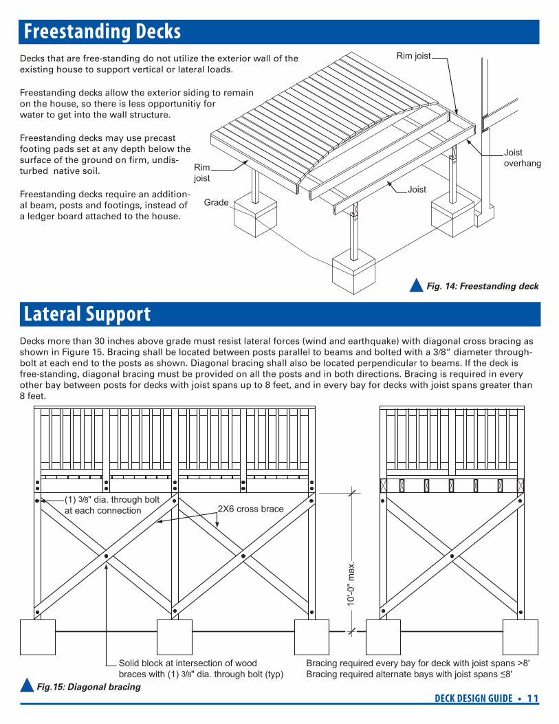
Rim joist
Rim joist
Joist
Joist overhang
Grade
2X6 cross brace(1) 3/8" dia. through bolt at each connection
Solid block at intersection of wood braces with (1) 3/8" dia. through bolt (typ)
Bracing required every bay for deck with joist spans >8'Bracing required alternate bays with joist spans <_8'
10'-0
" max
.
Freestanding DecksDecks that are free-standing do not utilize the exterior wall of the existing house to support vertical or lateral loads.
Freestanding decks allow the exterior siding to remain on the house, so there is less opportunitiy for water to get into the wall structure.
Freestanding decks may use precast footing pads set at any depth below the surface of the ground on fi rm, undis-turbed native soil.
Freestanding decks require an addition-al beam, posts and footings, instead of a ledger board attached to the house.
Fig. 14: Freestanding deck
Lateral SupportDecks more than 30 inches above grade must resist lateral forces (wind and earthquake) with diagonal cross bracing as shown in Figure 15. Bracing shall be located between posts parallel to beams and bolted with a 3/8” diameter through-bolt at each end to the posts as shown. Diagonal bracing shall also be located perpendicular to beams. If the deck is free-standing, diagonal bracing must be provided on all the posts and in both directions. Bracing is required in every other bay between posts for decks with joist spans up to 8 feet, and in every bay for decks with joist spans greater than 8 feet.
Fig.15: Diagonal bracing
12 • DECK DESIGN GUIDE
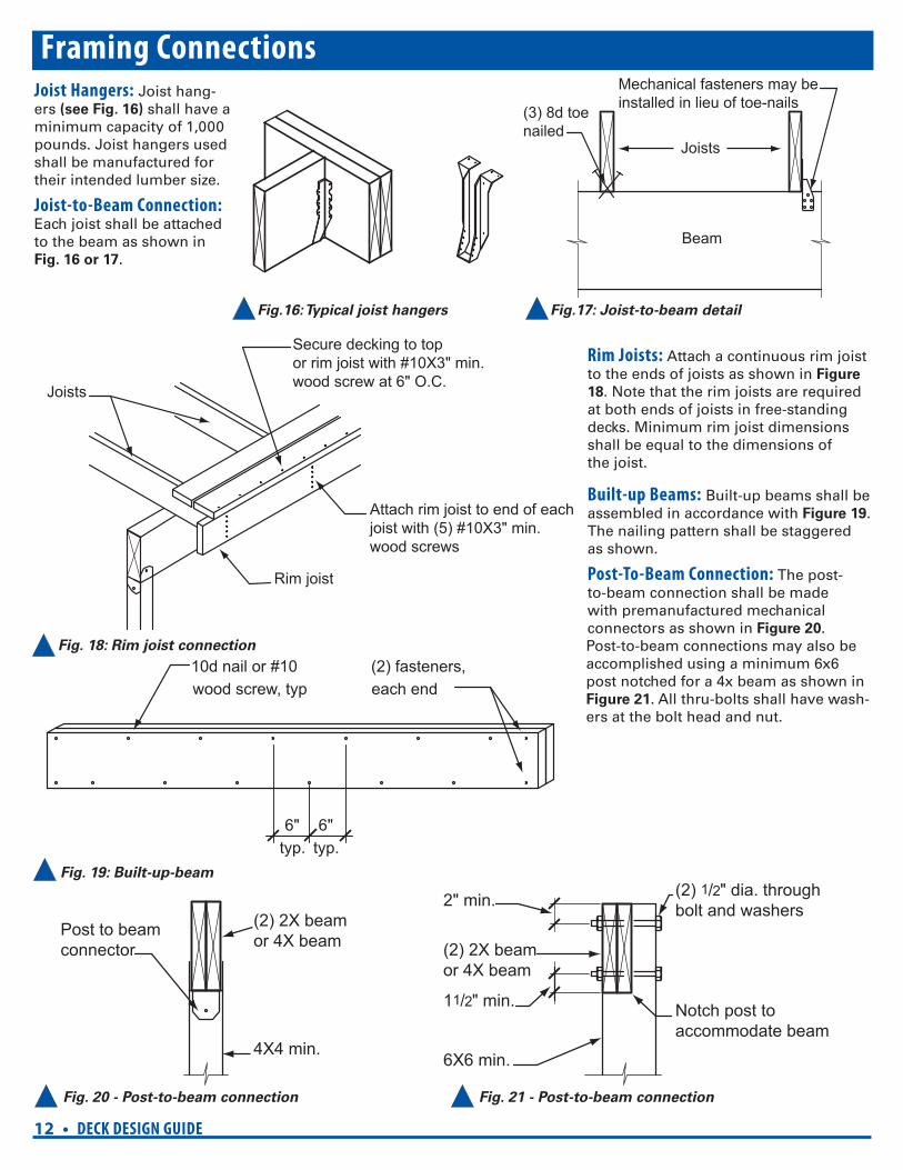
Attach rim joist to end of eachjoist with (5) #10X3" min.wood screws
Secure decking to topor rim joist with #10X3" min.wood screw at 6" O.C. Joists
Rim joist
4X4 min.
Post to beamconnector
(2) 2X beamor 4X beam
2" min.
Notch post toaccommodate beam
(2) 1/2" dia. throughbolt and washers
11/2" min.
(2) 2X beamor 4X beam
6X6 min.
10d nail or #10 wood screw, typ
(2) fasteners, each end
6"typ.
6"typ.
Beam
Mechanical fasteners may beinstalled in lieu of toe-nails
Joists
(3) 8d toenailed
Fig. 18: Rim joist connection
Framing ConnectionsJoist Hangers: Joist hang-ers (see Fig. 16) shall have a minimum capacity of 1,000 pounds. Joist hangers used shall be manufactured for their intended lumber size.
Joist-to-Beam Connection: Each joist shall be attached to the beam as shown in Fig. 16 or 17.
Fig.16: Typical joist hangers Fig.17: Joist-to-beam detail
Rim Joists: Attach a continuous rim joist to the ends of joists as shown in Figure
18. Note that the rim joists are required at both ends of joists in free-standing decks. Minimum rim joist dimensions shall be equal to the dimensions of the joist.
Built-up Beams: Built-up beams shall be assembled in accordance with Figure 19. The nailing pattern shall be staggered as shown.
Post-To-Beam Connection: The post-to-beam connection shall be made with premanufactured mechanical connectors as shown in Figure 20. Post-to-beam connections may also be accomplished using a minimum 6x6 post notched for a 4x beam as shown in Figure 21. All thru-bolts shall have wash-ers at the bolt head and nut.
Fig. 19: Built-up-beam
Fig. 20 - Post-to-beam connection Fig. 21 - Post-to-beam connection
DECK DESIGN GUIDE • 13
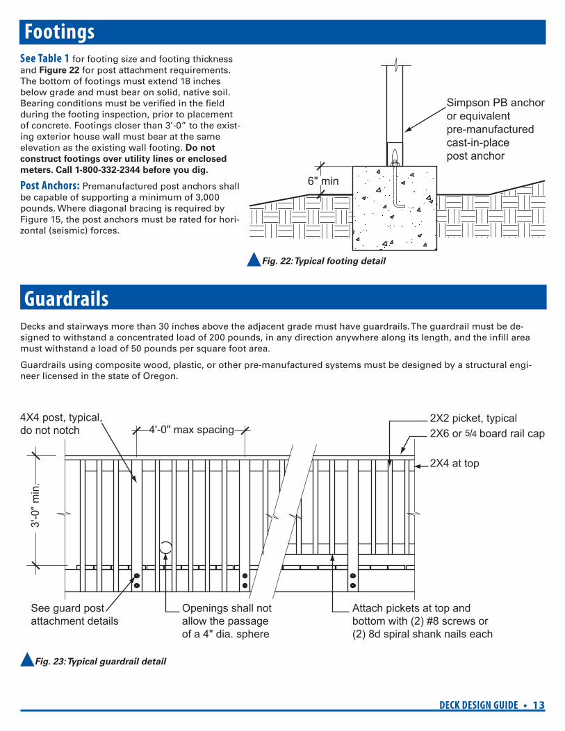
Simpson PB anchoror equivalentpre-manufacturedcast-in-placepost anchor
6" min
4'-0" max spacing
3'-0
" min
.
Openings shall not allow the passage of a 4" dia. sphere
See guard post attachment details
Attach pickets at top andbottom with (2) #8 screws or (2) 8d spiral shank nails each
2X4 at top
2X2 picket, typical2X6 or 5/4 board rail cap
4X4 post, typical,do not notch
FootingsSee Table 1 for footing size and footing thickness and Figure 22 for post attachment requirements. The bottom of footings must extend 18 inches below grade and must bear on solid, native soil. Bearing conditions must be verifi ed in the fi eld during the footing inspection, prior to placement of concrete. Footings closer than 3’-0” to the exist-ing exterior house wall must bear at the same elevation as the existing wall footing. Do not
construct footings over utility lines or enclosed
meters. Call 1-800-332-2344 before you dig.
Post Anchors: Premanufactured post anchors shall be capable of supporting a minimum of 3,000 pounds. Where diagonal bracing is required by Figure 15, the post anchors must be rated for hori-zontal (seismic) forces.
Fig. 22: Typical footing detail
GuardrailsDecks and stairways more than 30 inches above the adjacent grade must have guardrails. The guardrail must be de-signed to withstand a concentrated load of 200 pounds, in any direction anywhere along its length, and the infi ll area must withstand a load of 50 pounds per square foot area.
Guardrails using composite wood, plastic, or other pre-manufactured systems must be designed by a structural engi-neer licensed in the state of Oregon.
Fig. 23: Typical guardrail detail
14 • DECK DESIGN GUIDE
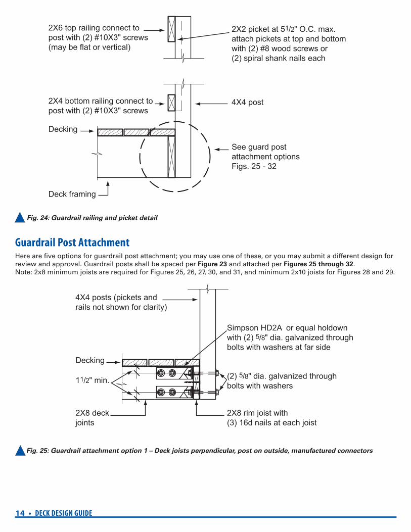
2X6 top railing connect topost with (2) #10X3" screws(may be flat or vertical)
2X4 bottom railing connect topost with (2) #10X3" screws
Deck framing
2X2 picket at 51/2" O.C. max. attach pickets at top and bottomwith (2) #8 wood screws or(2) spiral shank nails each
4X4 post
See guard post attachment optionsFigs. 25 - 32
Decking
4X4 posts (pickets andrails not shown for clarity)
Decking
2X8 deck joints
Simpson HD2A or equal holdown with (2) 5/8" dia. galvanized throughbolts with washers at far side
(2) 5/8" dia. galvanized throughbolts with washers
2X8 rim joist with(3) 16d nails at each joist
11/2" min.
Fig. 24: Guardrail railing and picket detail
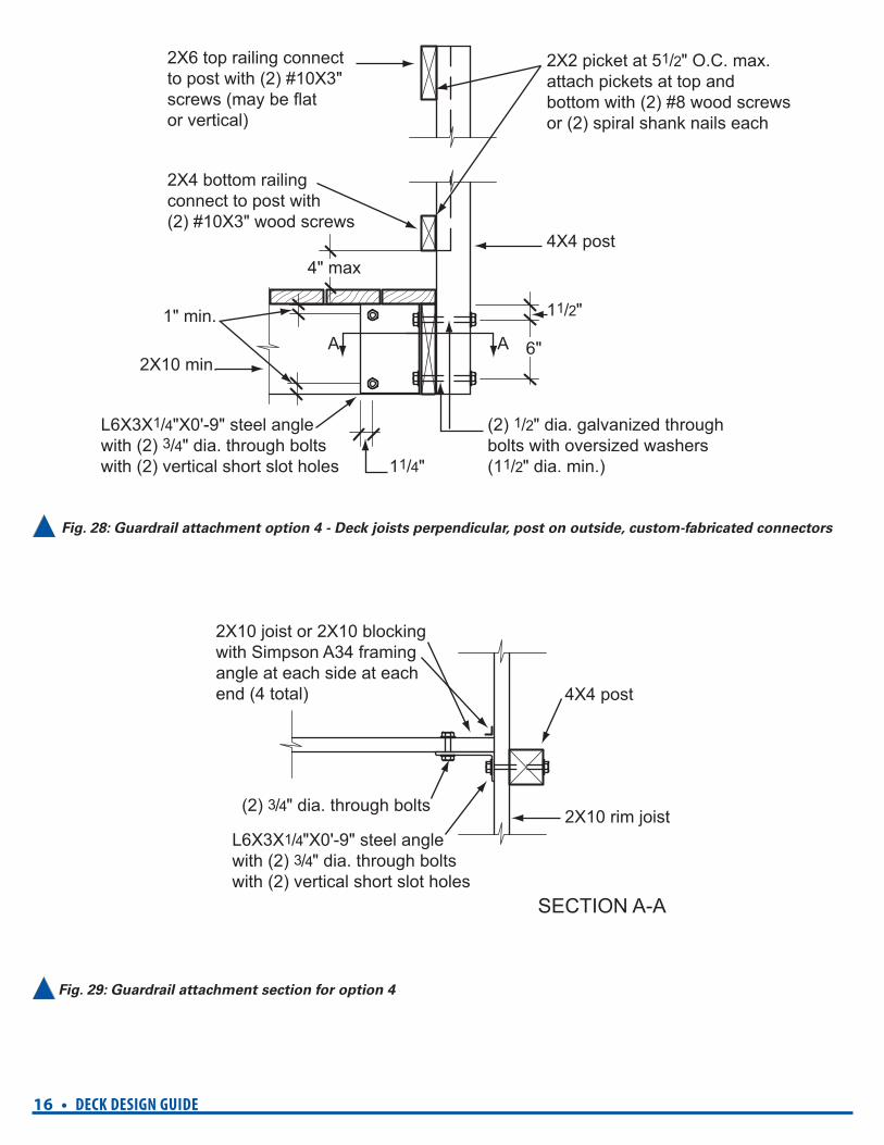
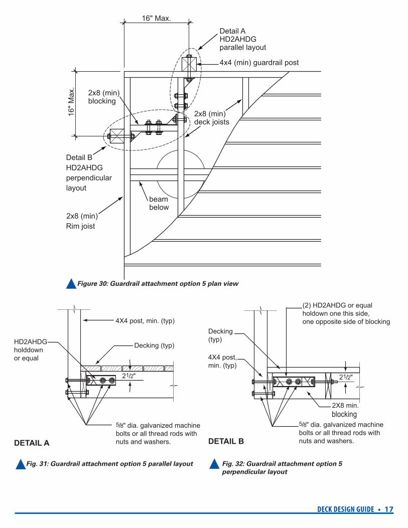
Guardrail Post AttachmentHere are fi ve options for guardrail post attachment; you may use one of these, or you may submit a different design for review and approval. Guardrail posts shall be spaced per Figure 23 and attached per Figures 25 through 32.Note: 2x8 minimum joists are required for Figures 25, 26, 27, 30, and 31, and minimum 2x10 joists for Figures 28 and 29.
Fig. 25: Guardrail attachment option 1 – Deck joists perpendicular, post on outside, manufactured connectors
DECK DESIGN GUIDE • 15
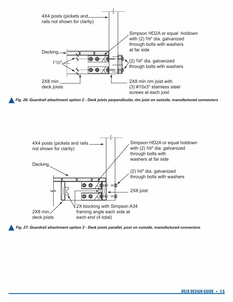
2X8 min.deck joists
11/2"
Decking
4X4 posts (pickets and rails not shown for clarity)
Simpson HD2A or equal holdown with (2) 5/8" dia. galvanizedthrough bolts with washersat far side
2X8 min rim joist with(3) #10x3" stainless steelscrews at each joist
(2) 5/8" dia. galvanizedthrough bolts with washers
2X8 min.deck joists
Decking
4X4 posts (pickets and railsnot shown for clarity)
Simpson HD2A or equal holdown with (2) 5/8" dia. galvanizedthrough bolts withwashers at far side
(2) 5/8" dia. galvanizedthrough bolts with washers
2X8 joist
2X blocking with Simpson A34framing angle each side at each end (4 total)
Fig. 26: Guardrail attachment option 2 - Deck joists perpendicular, rim joist on outside, manufactured connectors
Fig. 27: Guardrail attachment option 3 - Deck joists parallel, post on outside, manufactured connectors
16 • DECK DESIGN GUIDE
2X10 min.
1" min.
2X4 bottom railing connect to post with (2) #10X3" wood screws
2X6 top railing connectto post with (2) #10X3"screws (may be flat or vertical)
2X2 picket at 51/2" O.C. max.attach pickets at top and bottom with (2) #8 wood screwsor (2) spiral shank nails each
L6X3X1/4"X0'-9" steel anglewith (2) 3/4" dia. through boltswith (2) vertical short slot holes
(2) 1/2" dia. galvanized throughbolts with oversized washers(11/2" dia. min.)
AA
11/4"
6"
11/2"
4" max4X4 post
(2) 3/4" dia. through bolts
2X10 joist or 2X10 blocking with Simpson A34 framing angle at each side at each end (4 total) 4X4 post
2X10 rim joist
SECTION A-A
L6X3X1/4"X0'-9" steel angle with (2) 3/4" dia. through bolts with (2) vertical short slot holes
Fig. 28: Guardrail attachment option 4 - Deck joists perpendicular, post on outside, custom-fabricated connectors
Fig. 29: Guardrail attachment section for option 4
DECK DESIGN GUIDE • 17
16" Max.
Detail AHD2AHDGparallel layout
Detail BHD2AHDG perpendicular layout
16" M
ax.
2x8 (min)deck joists
4x4 (min) guardrail post
2x8 (min)blocking
beambelow
2x8 (min) Rim joist
4X4 post, min. (typ)
5/8" dia. galvanized machinebolts or all thread rods withnuts and washers.
21/2"
Decking (typ)HD2AHDGholddownor equal
DETAIL A
2X8 min. blocking
5/8" dia. galvanized machinebolts or all thread rods withnuts and washers.
(2) HD2AHDG or equalholdown one this side,one opposite side of blocking
4X4 post, min. (typ)
21/2"
Decking (typ)
DETAIL B
Figure 30: Guardrail attachment option 5 plan view
Fig. 31: Guardrail attachment option 5 parallel layout Fig. 32: Guardrail attachment option 5
perpendicular layout
18 • DECK DESIGN GUIDE
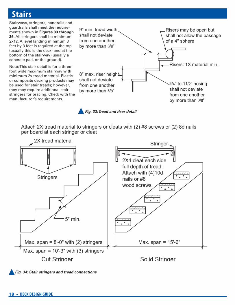
Max. span = 8'-0" with (2) stringers
Max. span = 10'-3" with (3) stringers
5" min.
Max. span = 15'-6"
2X tread material
Stringers
Stringer
Attach 2X tread material to stringers or cleats with (2) #8 screws or (2) 8d nailsper board at each stringer or cleat
2X4 cleat each sidefull depth of tread:Attach with (4)10d nails or #8 wood screws
Cut Stringer Solid Stringer
9" min. tread widthshall not deviatefrom one anotherby more than 3/8"
8" max. riser heightshall not deviatefrom one anotherby more than 3/8"
3/4" to 11/2" nosingshall not deviatefrom one anotherby more than 3/8"
Risers may be open butshall not allow the passageof a 4" sphere
Risers: 1X material min.
StairsStairways, stringers, handrails and guardrails shall meet the require-ments shown in Figures 33 through
36. All stringers shall be minimum 2x12. A level landing minimum 3 feet by 3 feet is required at the top (usually this is the deck) and at the bottom of the stairway (usually a concrete pad, or the ground).
Note: This stair detail is for a three-foot wide maximum stairway with minimum 2x tread material. Plastic or composite decking products may be used for stair treads; however, they may require additional stair stringers for bracing. Check with the manufacturer’s requirements.
Fig. 34: Stair stringers and tread connections
Fig. 33: Tread and riser detail
DECK DESIGN GUIDE • 19
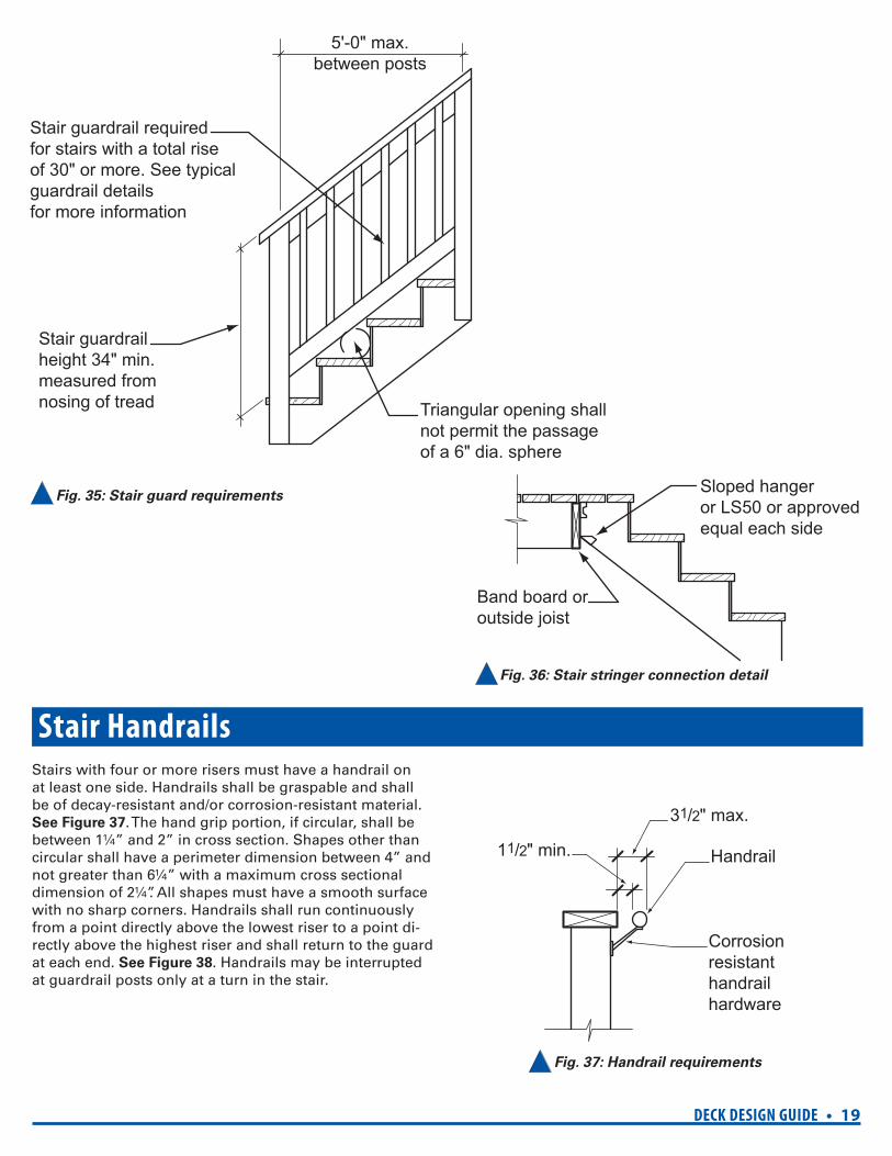
Stair guardrail required for stairs with a total rise of 30" or more. See typical guardrail detailsfor more information
Stair guardrailheight 34" min.measured fromnosing of tread Triangular opening shall
not permit the passage of a 6" dia. sphere
5'-0" max.between posts
Sloped hangeror LS50 or approvedequal each side
Band board oroutside joist
31/2" max.
11/2" min. Handrail
Corrosionresistanthandrailhardware
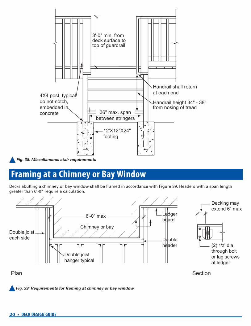
Stair HandrailsStairs with four or more risers must have a handrail on at least one side. Handrails shall be graspable and shall be of decay-resistant and/or corrosion-resistant material. See Figure 37. The hand grip portion, if circular, shall be between 1¼” and 2” in cross section. Shapes other than circular shall have a perimeter dimension between 4” and not greater than 6¼” with a maximum cross sectional dimension of 2¼”. All shapes must have a smooth surface with no sharp corners. Handrails shall run continuously from a point directly above the lowest riser to a point di-rectly above the highest riser and shall return to the guard at each end. See Figure 38. Handrails may be interrupted at guardrail posts only at a turn in the stair.
Fig. 35: Stair guard requirements
Fig. 36: Stair stringer connection detail
Fig. 37: Handrail requirements
20 • DECK DESIGN GUIDE
3'-0" min. from deck surface to top of guardrail
Handrail height 34" - 38" from nosing of tread
36" max. spanbetween stringers
Handrail shall returnat each end4X4 post, typical
do not notch, embedded in concrete
12'X12"X24"footing
6'-0" max
Chimney or bay
Double header
Ledger board
Double joisteach side
Double joisthanger typical
Decking may extend 6" max
(2) 1/2" dia through boltor lag screws at ledger
Plan Section
Fig. 38: Miscellaneous stair requirements
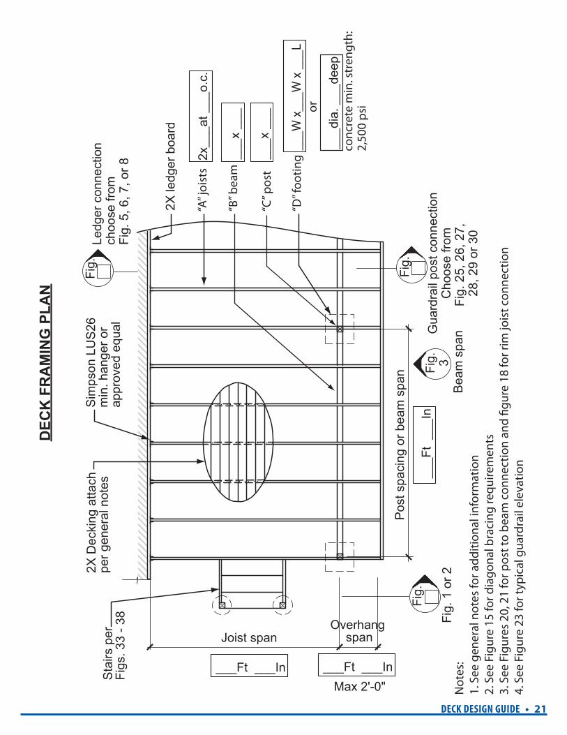
Framing at a Chimney or Bay WindowDecks abutting a chimney or bay window shall be framed in accordance with Figure 39. Headers with a span length greater than 6’-0” require a calculation.
Fig. 39: Requirements for framing at chimney or bay window
DECK DESIGN GUIDE • 21
2X D
ecki
ng a
ttach
pe
r gen
eral
not
es
Sta
irs p
erFi
gs. 3
3 - 3
8
Pos
t spa
cing
or b
eam
spa
n
Joist span
___Ft ___In
___
Ft _
__In
___x
___
___x
___
___W
x__
_W x
___
L
2x__
_at _
__o.
c.
___d
ia. _
__de
ep
___Ft ___In
Overhang span
Max 2'-0"
Sim
pson
LU
S26
min
. han
ger o
rap
prov
ed e
qual
2X le
dger
boa
rd
Gua
rdra
il po
st c
onne
ctio
nC
hoos
e fro
mFi
g. 2
5, 2
6, 2
7,
28, 2
9 or
30
Fig.
Fig.
Ledg
er c
onne
ctio
nch
oose
from
Fig.
5, 6
, 7, o
r 8
Fig.
1 o
r 2B
eam
spa
n
Fig.
Fig. 3
DEC
K F
RA
MIN
G P
LAN
Not
es:
1. S
ee g
ener
al n
otes
for a
dditi
onal
info
rmat
ion
2. S
ee F
igur
e 15
for d
iago
nal b
raci
ng re
quire
men
ts3.
See
Fig
ures
20,
21
for p
ost t
o be
am c
onne
ctio
n an
d fig
ure
18 fo
r rim
jois
t con
nect
ion
4. S
ee F
igur
e 23
for t
ypic
al g
uard
rail
elev
atio
n
“B” b
eam
or
conc
rete
min
. str
engt
h:2,
500
psi
“A” j
oist
s
“D” f
ootin
g
“C” p
ost

22 • DECK DESIGN GUIDE res_deck 12/13/10
Helpful InformationBureau of Development Services City of Portland, Oregon 1900 SW 4th Avenue, Portland, OR 97201www.portlandoregon.gov/bds
General Offi ce Hours: Monday through Friday, 8:00 am to 5:00 pm
BDS main number: 503-823-7300
Permit Information is available at the following location:
Development Services Center (First Floor) For Hours Call 503-823-7310 | Select option 1
Permitting Services (Second Floor) For Hours Call 503-823-7310 | Select option 4
Important Telephone NumbersBDS main number .........................................503-823-7300DSC automated information line ...................503-823-7310Building code information .............................503-823-1456Zoning code information .................................503-823-7526Permit information for electrical,mechanical, plumbing, sewerand sign ............................................................503-823-7363Permitting process and fees ............................503-823-7357Permit resources and records .........................503-823-7660BDS 24 hour inspection request line requires IVR number and three digittype of inspection code .................................. 503-823-7000Residential information forone and two family dwellings .........................503-823-7388Environmental Soils.........................................503-823-7790PDOT Engineering............................................503-823-7002City of Portland TTY .......................................503-823-6868Call before you dig ...........................................503-246-6699
Scheduling an inspection• Call 503-823-7000, the BDS 24 hour inspection
request line
• Enter your IVR or permit number
• Enter the three-digit inspection code for the type of inspection you are requesting
• Enter a phone number where you can be reached during weekdays and if you want the inspection in the morning or afternoon
• There must be an adult over age 18 to allow the inspector entry
✔ To be safe, remember to call before you dig, and have your underground utility lines located.
✔ Check with PDOT regarding the width of the right-of-way if you are building in your front yard.
✔ Depending on your location and the specifi cations of your project, building and/or zoning permits may be required.
✔ Some zones have special requirements which could affect your outdoor project.
✔ If you have any questions or concerns about your project, check with staff in the DSC about zoning and building issues.
Visit our Web site
www.portlandoregon.gov/bds
Note: All information in this brochure is subject to change.
For more detailed information regarding the bureau’s
hours of operation and available services;