Embed Size (px)
Citation preview

ME 474-674 Winter 2008 Slides 9 -1
More info: “Materials Selection in Mechanical Design”, Chapters 11 and 12
Cross sectional Shape Selection
Materials have propertiesStrength, stiffness, electrical conductivity, etc.
A component or structure is a material made into a particular shapeDifferent shapes are more or less efficient for carrying a particular type of loading An efficient shape is one that uses the least amount of material for a given strength or stiffness

ME 474-674 Winter 2008 Slides 9 -2
Mechanical loading and associated components
Axial LoadingTension – ties or tie rods
Compression – columns
Bending – beams
Torsion – shafts
Each type of loading has a different failure mode, and some shapes are more efficient than others for that loading

ME 474-674 Winter 2008 Slides 9 -3
Ties or Tie rods
Tensile axial loading
The stiffness of a tie rod for a given material depends only on the cross sectional area A and not the shape
The strength of a tie rod depends only on the cross sectional area A and not the shape
Therefore in tensile loading all shapes of the same cross-sectional area are equivalent
AF
LAEFS
AEFL
=
==
=
σ
δ
δ

ME 474-674 Winter 2008 Slides 9 -4
Elastic Bending
Appendix A-3 gives the deflection of beams as a function of the type of loading. Generally
The stiffness of a beam S is defined as the ratio of load to displacement
Using either definition, S is proportional to EI
E = elastic modulus of the materialI = moment of inertia of the cross section
EICML
orEIC
FL
1
2
1
3
=
=
δ
δ
δ
δ
MS
or
FS
=
=

ME 474-674 Winter 2008 Slides 9 -5
Elastic Bending
I = Moment of inertia of the cross section
Table 11.2 gives the section properties of different shapesFor a circular cross section
If S is the stiffness for another shape with the same cross sectional area made of the same material and subject to the same loading, then the shape factor for elastic bending is defined as
∫−
=sectionCross
dAyI 2
ππ
π
44
24
2
ArI
rA
O ==
=
21
1 4AI
EICEIC
SS
OO
eB πφ ===

ME 474-674 Winter 2008 Slides 9 -6
Elastic Bending
Derive shape factor for elastic bending of
Square cross-section of side a
Hollow tube of radius r and thickness t where r >> t
For a square cross section
For a hollow tube
05.1124
====πφ
O
sq
O
sqeB EI
EISS
tr
AI
EIEI
SS
OO
eB ==== 24πφ

ME 474-674 Winter 2008 Slides 9 -7
Elastic Bending - Square cross-section beam
For a square cross-section of side a
Compare with a circle with the same area A
Shape factor during elastic bending of a square cross-section relative to a circular cross section of the same area is:
Therefore, a square cross-section is about 5% stiffer than a circular cross-section
1212
24
2
AaI
aA
sq ==
=
Osq II124π
=
( )( ) 05.1
124
4/12/
2
2
=====π
πφ
AA
II
SS
O
sq
O
sqeB

ME 474-674 Winter 2008 Slides 9 -8
Elastic Bending – Tubular beam
For a tubular beam with radius r and wall thickness t where r >> t
Shape factor during elastic bending of a tubular beam relative to a circular cross-section of the same area is:
Therefore, a thin walled tubular beam with r = 10t is 10 times as stiff as a circular cross-section beam of the same area
trIrtA
tube3
2π
π
=
=
( ) ( ) tr
rttr
AI
II
SS tube
O
tube
O
tubeeB ===== 2
3
2 24
4/ πππ
πφ
Please note that the derivations here assume a circle as the reference shape. The text book assumes the reference shape to be a square.

ME 474-674 Winter 2008 Slides 9 -9
Elastic Bending
The shape factor φBe is dimensionless, i.e. it is a pure number that
characterizes the cross-sectional shape relative to a circular cross-section
Increasing size with constant shape
I sections withφB
e = 10
Hollow tubes withφB
e = 10

ME 474-674 Winter 2008 Slides 9 -10
Elastic Bending
EduPack Level 3 includes most of the commercially available structural shapes made from different materials.
Using a plot of the moment of inertia versus section area one can compare different structural shapes
Section area, A (m^2)1e-4 1e-3 0.01 0.1
Sec
ond
mom
ent o
f are
a (m
ajor
), I_
max
(m^4
)
1e-11
1e-10
1e-9
1e-8
1e-7
1e-6
1e-5
1e-4
1e-3
0.01
Phi=100
Extruded Aluminum circular hollow (Y.S. 255MPa)-(32x2.6)
Hot Rolled Steel (Y.S. 355MPa) Universal Beam-(203x133x25)
Hot Fin. Steel (Y.S. 355MPa) Rect.Hollow -(150x150x5.0)
Pultruded GFRP Vinyl Ester I-section-(102x51x2.1)
24AIe
B πφ =
ME 474-674 Winter 2008 Slides 9 -11
Failure in Bending
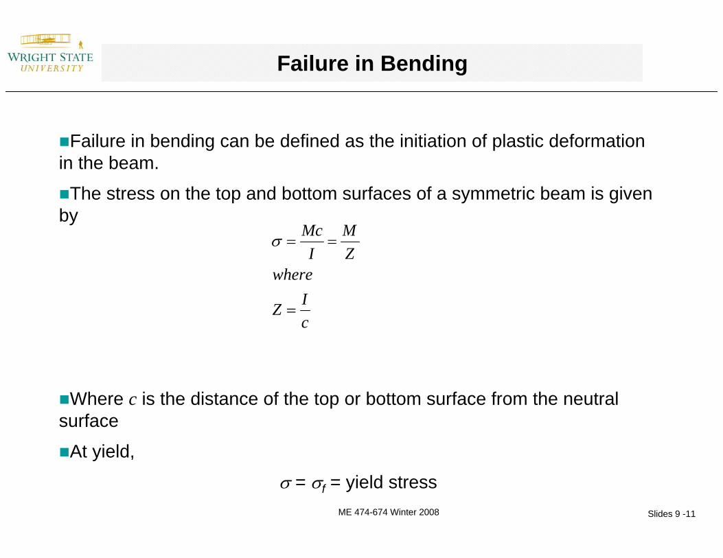
Failure in bending can be defined as the initiation of plastic deformation in the beam.
The stress on the top and bottom surfaces of a symmetric beam is given by
Where c is the distance of the top or bottom surface from the neutral surface
At yield,
σ = σf = yield stress
cIZ
whereZM
IMc
=
==σ
ME 474-674 Winter 2008 Slides 9 -12
Failure in Bending
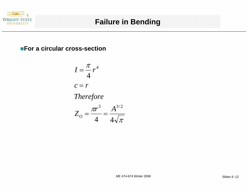
For a circular cross-section
ππ
π
44
4
2/33
4
ArZ
Thereforerc
rI
O ==
=
=

ME 474-674 Winter 2008 Slides 9 -13
Failure in Bending
Define the shape factor for failure in bending as
Derive
For a square of side a
For a hollow cylinder of radius r and wall thickness t, where r >> t
18.13
2===
πφO
sqfB Z
Z
tr
ZZ
O
fB 8==φ
O
fB Z
Z=φ
ME 474-674 Winter 2008 Slides 9 -14
Failure in Bending – Square cross section beam
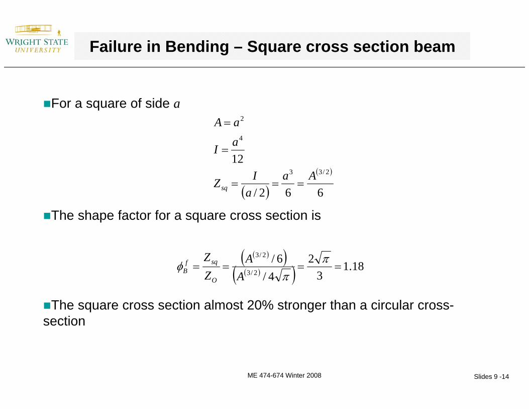
For a square of side a
The shape factor for a square cross section is
The square cross section almost 20% stronger than a circular cross-section
( )( )
662/
122/33
4
2
Aaa
IZ
aI
aA
sq ===
=
=
( )( )( )( ) 18.1
32
4/6/
2/3
2/3
====π
πφ
AA
ZZ
O
sqfB

ME 474-674 Winter 2008 Slides 9 -15
Failure in Bending – Tubular beam
For a tubular beam with radius r and wall thickness t where r >> t
The shape factor for a tubular beam is
The tubular beam with r = 10t has a shape factor of 8.9, i.e., the tubular beam is almost 9 times as strong as a circular cross-section beam
trrIZ
trIrtA
tube2
3
2
π
π
π
==
=
=
( )( ) ( )( ) tr
rttr
Atr
ZZ
O
tubefB 8
24
4/ 2/3
2
2/3
2
====πππ
ππφ

ME 474-674 Winter 2008 Slides 9 -16
Elastic Torsion
During elastic torsion, the angle of twist per unit length is
Where T is the torque, J is the polar moment of inertia, and G is the shear modulus of the material.
The stiffness of a solid circular shaft in torsion ST is defined as the ratio of load to angle of twist per unit length
The shape factor for a different cross section is defined as
JGT
=θ
ππ
π
22
24
2
ArJ
rA
==
=
GJTS OTO==
θ
( )πφ2/2A
JGJGJ
SS
OT
TeT
O
===

ME 474-674 Winter 2008 Slides 9 -17
Elastic Torsion
For a hollow shaft with radius r and wall thickness t where r >> t
Shape factor for elastic torsion is
Therefore, a thin walled shaft with r = 10t is 10 times as stiff as a circular cross-section shaft of the same area
trJrtA
322π
π
≈
=
( ) tr
trtr
Atre
T === 222
32
2
3
44
2/2
ππ
ππφ

ME 474-674 Winter 2008 Slides 9 -18
Failure by plastic deformation during Torsion
The shear stress at the surface of a cylindrical shaft subject to a torque T is
Failure occurs when the stress reaches the shear yield stress, or one-half of the tensile yield stress
The shape factor for a shaft of a different cross-section can be defined as
( )
ππ
π
τ
22
2
/
2/33
4
ArQ
and
rJ
whereQT
rJT
JTr
O
O
OOO
==
=
===
O
ff Q
T==
2σ
τ
2/32AQ
O
fT πφ ==

ME 474-674 Winter 2008 Slides 9 -19
Shape factor for failure in Torsion of a Hollow Shaft
For a hollow shaft with radius r and wall thickness t where r >> t
Shape factor is
Therefore, a thin walled shaft with r = 10t is 4.5 times as strong as a circular cross-section shaft of the same area
trrJQ
trJrtA
2
3
2
22
π
π
π
==
≈
=
( ) tr
rttr
AQf
T2
2222 2/3
2
2/3 ===ππππφ

ME 474-674 Winter 2008 Slides 9 -20
Homework Assignment
Show that the shape factor of elastic buckling is the same as that for elastic bending

ME 474-674 Winter 2008 Slides 9 -21
Empirical upper limits for the different shape factors
The limits to the different shape factors derived above based on manufacturing considerations, as well as competing failure mechanisms is given in Table 11.4
3<6Elastomers1315Wood (solid section)45812Polymers (nylon)792639GFRP and CFRP8103144AA 60617132565Structural Steel
Material ( )maxeBφ ( )max
eTφ ( )max
fBφ ( )max
fTφ
ME 474-674 Winter 2008 Slides 9 -22
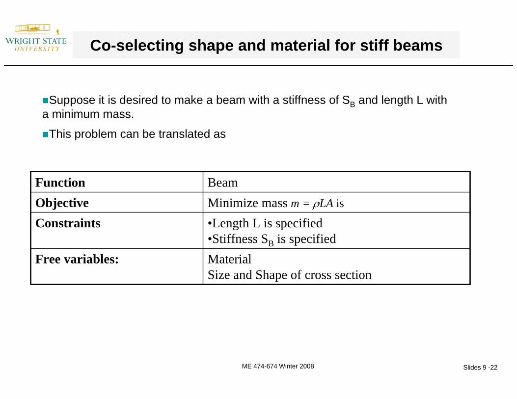
Co-selecting shape and material for stiff beams
Suppose it is desired to make a beam with a stiffness of SB and length L with a minimum mass.
This problem can be translated as
MaterialSize and Shape of cross section
Free variables:
•Length L is specified•Stiffness SB is specified
ConstraintsMinimize mass m = ρLA is ObjectiveBeamFunction

ME 474-674 Winter 2008 Slides 9 -23
Co-selecting shape and material for stiff beams
The stiffness in bending is given by
where C1 depends upon exactly how the load is distributed
If we replace the moment of inertia I by
Then
31 LEICSB =
π
πφφ
4
4
2
2
AI
since
AII
O
EB
OEB
=
==
23
1
4A
LECS e
BB φπ
=

ME 474-674 Winter 2008 Slides 9 -24
Co-selecting shape and material for stiff beams
Eliminating A from the equation for mass m we get
The material index to be maximized is therefore
So if we want to co-select both shape and material for a stiff beam, the basis for comparison is the material index M, above.
Graphically, we can co-select materials and shape by assuming new material properties of E* and ρ*
( ) ⎥⎥⎦
⎤
⎢⎢⎣
⎡⎟⎟⎠
⎞⎜⎜⎝
⎛= 2/1
2/52/1
1
4E
LCSm
eB
B
φρπ
( ) ( )( )
( )*
*/
/ 2/12/12/1
ρφρφ
ρφ EEEM e
B
eB
eB ===

ME 474-674 Winter 2008 Slides 9 -25
Co-selecting shape and material for other loading
By a similar analysis, for elastic torsion, the material index is
For failure in bending it is
And for failure in torsion it is
( )ρ
φ2/2EM
fB=
( )ρ
φ2/3EM
fT=
( )ρ
φ2/1EM
eT=

ME 474-674 Winter 2008 Slides 9 -26
Example: The wing-spar of a human powered plane
See example 12.1 in the book
The human powered plane is basically a large model airplane capable of flying under the power of a human being
The design requirement is that the weight (or mass) of the plane be minimized
MaterialSize and Shape of cross section
Free variables:
•Length L is specified•Stiffness SB is specified
ConstraintsMinimize massObjectiveWing sparFunction

ME 474-674 Winter 2008 Slides 9 -27
Example: The wing-spar of a human powered plane
231071.5 – 1.6100 – 160CFRP142032.8 – 2.8271 – 73AA-7075-T69251.87.82 – 7.84200 – 210Steel12280.36 – 0.449.8 – 11.9Spruce152100.17 – 0.244.2 – 5.2Balsa Wood
Modified Material Index (EφB
e)1/2/ ρ
Shape factorφB
e
Material Index(E1/2/ρ)
Densityρ (Mg/m3)
ModulusE (GPa)
Material
Without taking shape into account, Balsa wood appears to have the best properties, and aluminum has a relatively poor performance
If we take shape into account, using typical values of the shape factor for beams of different materials, CFRP is best, while AA-7075 performs as well as the woods
Early planes were made of balsa, but later designs used aluminum or CFRP (if cost was not an issue).