Embed Size (px)
Citation preview

EURASIP Journal on Wireless Communications and Networking 2005:5, 672–685c© 2005 Chiara Buratti et al.
Cross-Layer Design of an Energy-Efficient ClusterFormation Algorithmwith Carrier-SensingMultipleAccess for Wireless Sensor Networks
Chiara BurattiIEIIT-BO/CNR, DEIS, University of Bologna and CNIT, Viale Risorgimento 2, 40136 Bologna, ItalyEmail: [email protected]
Andrea GiorgettiIEIIT-BO/CNR, DEIS, University of Bologna and CNIT, Viale Risorgimento 2, 40136 Bologna, ItalyEmail: [email protected]
Roberto VerdoneIEIIT-BO/CNR, DEIS, University of Bologna and CNIT, Viale Risorgimento 2, 40136 Bologna, ItalyEmail: [email protected]
Received 1 July 2004; Revised 23 May 2005
A new energy-efficient scheme for data transmission in a wireless sensor network (WSN) is proposed, having in mind a typicalapplication including a sink, which periodically triggers the WSN, and nodes uniformly distributed over a specified area. Rout-ing, multiple access control (MAC), physical, energy, and propagation aspects are jointly taken into account through simulation;however, the protocol design is based on some analytical considerations reported in the appendix. Information routing is basedon a clustered self-organized structure; a carrier-sensing multiple access (CSMA) protocol is chosen at MAC layer. Two differentscenarios are examined, characterized by different channel fading rates. Four versions of our protocol are presented, suitably ori-ented to the two different scenarios; two of them implement a cross-layer (CL) approach, where MAC parameters influence boththe network and physical layers. Performance is measured in terms of network lifetime (related to energy efficiency) and packetloss rate (related to network availability). The paper discusses the rationale behind the selection of MAC protocols for WSNs andprovides a complete model characterization spanning from the network layer to the propagation channel. The advantages of theCL approach, with respect to an algorithm which belongs to the well-known class of low-energy adaptive clustering hierarchy(LEACH) protocols, are shown.
Keywords andphrases:wireless sensor networks, routing algorithms,MAC protocols, energy savings strategies, cross-layer design.
1. INTRODUCTION
Wireless sensor networks (WSNs) are composed of low-costlow-energy nodes, whose battery is normally not replacedduring network lifetime. Nodes sense the environment andare equipped with radio transceivers which allow them to actas both transmitters and route-and-forward devices.
Typical applications include a sink, which periodicallytriggers the WSN, and a large number of nodes deployedwithout detailed planning in a given area.
This is an open access article distributed under the Creative CommonsAttribution License, which permits unrestricted use, distribution, andreproduction in any medium, provided the original work is properly cited.
The characteristics of WSNs and their applications makeenergy conservation and self-organization primary goalswith respect to per-node fairness and latency [1, 2, 3, 4].As a result, the main performance figure in these cases isnetwork lifetime, that is, the time elapsing between net-work deployment and the moment when the percentage ofnodes still active falls below a given threshold which dependson the application. Accordingly, many self-organizing andenergy-efficient protocols have been recently developed fordata transmission in WSNs [5, 6, 7, 8, 9, 10, 11, 12, 13].
The cross-layer design (CLD) paradigm seems to be apromising solution to solve the conflicts between require-ments of large-scale and long lifetime and the constraints oflimited node resources and low battery capacity [14]. Two

Cross-Layer Design of an Energy-Efficient Cluster Formation Algorithm 673
different CL approaches exist: the first considers a layeredstructure of protocols, with vertical entities providing ex-change of data between all layers; the second, instead, con-siders a protocol structure where the different layers cannotbe distinguished. The former approach, instead, is simpler,as it keeps the existing protocol layer structure and providesadditional exchange of information between layers via a sin-gle vertical entity [15]. In this approach, it is important toidentify traditionally hidden interdependencies among lay-ers and find relevant metrics that capture such dependenciesthat have to be exchanged among layers to optimally adaptto network dynamics. Some CL works are based on this ap-proach, but most of them are focused on the interactions be-tween two layers only and consider, mainly, the performancein terms of network lifetime. In [16], the authors develop CLinteractions between MAC and network layers to achieve en-ergy conservation; in particular, the MAC layer provides thenetwork layer with information pertaining to successful re-ception of packets and the network layer, on its turn, choosesthe route that minimizes the error probability. In [17], a clus-ter design method that allows the evaluation of the optimumnumber of clusters to realize power saving and coverage isdeveloped; to do this, a dynamical adjusting of the numberof clusters is proposed.
Our approach refers to the one described above, where asuitable interplay between MAC and routing protocols, andphysical and MAC protocols are introduced; moreover, per-formance is evaluated either in terms of energy efficiency, orin terms of packets loss.
A routing protocol architecture that provides good re-sults in terms of energy efficiency for WSNs is low-energyadaptive clustering hierarchy (LEACH) [9, 10]. LEACH in-cludes a distributed cluster formation technique, which en-ables self-organization of large numbers of nodes with onenode per cluster acting as cluster head (CH), and algorithmsfor adapting clusters and rotating CH roles to evenly dis-tribute the energy load among all nodes. The nodes forwardtheir data to the sink through the CH according to a two-hopstrategy. Starting from the basic idea of LEACH, in [18], anew routing strategy, denoted as LEACH B, is proposed andthe performance shows improvements in terms of networklifetime in a large range of situations.
As far as MAC aspects are concerned, two main familiesof protocols can be considered: those based on collision-freestrategies and those relying on suitable retransmission tech-niques to overcome the potential collisions caused by unco-ordinated transmissions. The proper selection of the familyof MAC protocols is a critical issue for energy efficiency.
In the original proposal of LEACH [9, 10], a time di-vision multiple access (TDMA) schedule is defined by theCHs to ensure that there are no collisions among data mes-sages. However, this centralized control at the CH requiressuitable transmission of control packets which makes theprotocol complex; moreover, this overhead creates energyinefficiency. In [19], a self-organization protocol for WSNscalled self-organizing medium access control for sensor net-works (SMACS) is proposed. Each node maintains a TDMA-like frame in which nodes schedule different time slots to
communicate with its known neighbors. A different ap-proach, though still based on coordinated actions to avoidpacket collisions, can be found in sensor-MAC (S-MAC)[20], which sets the radio in sleeping mode during transmis-sion of other nodes. The contention mechanism is the sameas that in IEEE 802.11 using request-to-send (RTS) and clear-to-send (CTS) packets.
When dealing with collision-prone MAC techniques,carrier-sensing multiple access (CSMA) is a usual choice inWSNs [21]. The advantage here is that no extra signalling toschedule transmissions and coordinate data flows is required;on the other hand, collisions might occur, and suitable back-off algorithms are needed to recover data.
AnOMNET++ platform [22] is used in this paper to sim-ulate a WSN composed of several tens of nodes randomlyand uniformly distributed over a square area, accounting forrouting, MAC, physical, energy, and propagation aspects. Inparticular, we propose a novel cluster formation algorithm,that we name LEACH B+, which introduces the possibilityfor nodes to transmit to the sink, by using a direct path, whenit is energetically efficient, and is based on a new CH electionalgorithm which significantly improves network lifetime. Wealso introduce a time division between the data transmissionin the different phases of the algorithm, which allows the re-duction of the packet loss rate. Moreover, we employ a CSMAprotocol based on IEEE 802.11 [23]. If collisions are reducedby suitably dimensioning the average cluster size, this choiceleads to high energy efficiency. A relevant energy waste inCSMA protocols is owed to idle listening that occurs whenthe node is sensing the channel to check whether packets aresent. To avoid this energy loss, an ON/OFF modality whichconsists in turning off and on periodically radio componentscan be implemented as usual in WSNs [21].
We apply the CL paradigm to the design of a protocol forWSNs where MAC and routing (i.e., cluster formation) as-pects are jointly considered and optimized: the decisions tobe taken for cluster formation rely on parameters extractedfrom the MAC; also, some physical layer parameters (liketransmit power) are based on MAC layer protocol status.
We consider two different scenarios, in which the propa-gation channel fluctuations vary at different rates; it is shownthat the protocol design can take advantage of the knowledgeof the fading rate.
We study the network lifetime and the packet loss ratefor the two different scenarios and we make a comparisonbetween the protocols with and without the CL paradigm.
The paper is organized as follows. As in WSNs, the pro-tocol choices are application-specific, Section 2 describes thereference scenario and application, and discusses the choiceof the MAC protocol; Section 3 refers to LEACH B+ rout-ing protocols, with the details on the CHs election and thecluster formation algorithms when no CLD is considered,for the two different scenarios. Then, in Section 4, the MACstrategy is presented. Sections 5 and 6 are devoted to the de-scription of the physical and energy aspects, respectively. TheCL approach and its impact on the cluster formation algo-rithms previously presented in Section 3.2 are discussed inSection 7. Simulation results are reported in Section 8, and

674 EURASIP Journal on Wireless Communications and Networking
d
M
Dmax
Figure 1: Transmission flow during a round. Filled box: sink; filledcircles: cluster heads; circles: noncluster-head nodes.
the conclusions are drawn in the final section. The appendixpresents the new CH election algorithm proposed in this pa-per which shows very good performance improvement withrespect to the protocols previously presented in the litera-ture: the algorithm description is reported in the appendixto make the paper more readable.
2. REFERENCE SCENARIO AND APPLICATION
2.1. Reference scenario
The reference scenario we assume consists of NTOT sensorsrandomly and uniformly distributed over a square area (hav-ing sideM) and a sink located at a given distance d from thecenter of the square, as shown in Figure 1. The network mustbe able to provide the information detected by nodes to asink that periodically (every TR seconds) broadcasts a shortpacket that we call “start” and waits for the replies from thenodes. We denote by “round” the period of time between twosuccessive start packets sent by the sink. During each round,all sensors should send their information to the sink.
The wireless channel is assumed to be characterizedby random fluctuations that will be modeled as Gaussiandistributed when being in logarithmic scale. A distance-dependent path loss is also considered. The model is moti-vated by the presence, in many cases for WSNs, of obstacles(ground, foliage, cars, human bodies, depending on the ap-plication).
2.2. Reference application andmotivation for thechoice of LEACH and CSMA
This work, though presenting ideas, approaches, and resultswhich are much more general, has been inspired by a spe-cific application: the monitoring of a car parking area wherenodes sense the presence of cars and interact to communi-cate to a sink, which provides information to cars enteringthe parking area about the better way to reach the closestfree slot. Other specific applications that can be considered
are based, for example, on the estimation of a target multi-dimensional process such as, seismic waves through acousticsensors arrays, the ground temperature variations in a smallvolcanic site, or structural monitoring of buildings, by meansof samples captured by nodes randomly and uniformly dis-tributed. Samples are then transmitted to a sink with a self-organizing and distributed routing strategy.
As for network aspects, routing algorithms for WSNs canbe classified into three categories: multihop flat, hierarchical,and location-based [24]. In the first category, each node playsthe same role and sensors collaborate to perform the sensingtask. The second category, instead, refers to protocols wheresensors are organized in clusters, where particular tasks areassigned to cluster heads; thus, nodes have not all the samerole in the network [25, 26]. Finally, in the third kind of pro-tocols, sensors exploit the knowledge of their position in thenetwork, obtained, for example, through GPS. The multihopflat protocols may include scalability issues, whereas the hi-erarchical protocols (unless the number of levels of the hier-archy is unlimited) can be applied only in those cases wherethe maximum distance between nodes and the sink is not toolarge. We will set values of d andM not larger than 100mt, socluster-based algorithms like those belonging to the LEACHfamily represent a good choice.
Concerning MAC, the selection of a protocol belongingto the families of collision-free or collision-prone strategiesrequires suitable comparison between the time elapsing be-tween two start packets TR and the time coherence of the en-vironment Tcoh which is a measure of how slow or fast thechannel attenuation fluctuates.
In fact, when Tcoh is much larger than TR, a suitablescheduling of transmissions, which requires extra signallingbetween nodes, can be kept fixed for many rounds, thus re-ducing the impact of the related energy wasted on networklifetime. On the other hand, if this condition does not oc-cur, the channel tends to be independent in different rounds,and a collision-free protocol which tries to schedule trans-missions in order to avoid collisions becomes energy ineffi-cient since the extra signalling to manage the scheduling isrequired at each round.
The application we consider is characterized by values ofTR which are larger than, or of the same order as, Tcoh, andthe natural choice in this case is CSMA.
In particular, we will consider two different cases: the firstwith Tcoh � TR (scenario 1) and the second with Tcoh � TR
(scenario 2); more precisely, in the former case, the chan-nel fluctuations are completely uncorrelated at each round,whereas, in the second scenario, we assume a block-fadingmodel, where the random variables characterizing the prop-agation channel remain constant for two subsequent rounds,and then change according to a memoryless process.
The following assumptions concerning the application,are also made.
(i) Nodes and sink are still (no mobility).(ii) Nodes do not know their position in the area.(iii) Each node is aware of the sink position with respect to
a given reference coordinate system; in particular (as
Cross-Layer Design of an Energy-Efficient Cluster Formation Algorithm 675
Start i + 1Start i
TR
t
TCF TIC TTS TCF
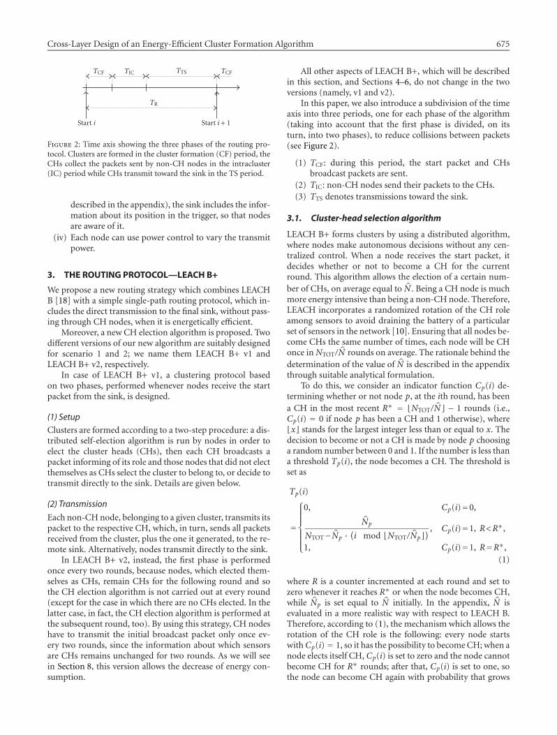
Figure 2: Time axis showing the three phases of the routing pro-tocol. Clusters are formed in the cluster formation (CF) period, theCHs collect the packets sent by non-CH nodes in the intracluster(IC) period while CHs transmit toward the sink in the TS period.
described in the appendix), the sink includes the infor-mation about its position in the trigger, so that nodesare aware of it.
(iv) Each node can use power control to vary the transmitpower.
3. THE ROUTING PROTOCOL—LEACH B+
We propose a new routing strategy which combines LEACHB [18] with a simple single-path routing protocol, which in-cludes the direct transmission to the final sink, without pass-ing through CH nodes, when it is energetically efficient.
Moreover, a new CH election algorithm is proposed. Twodifferent versions of our new algorithm are suitably designedfor scenario 1 and 2; we name them LEACH B+ v1 andLEACH B+ v2, respectively.
In case of LEACH B+ v1, a clustering protocol basedon two phases, performed whenever nodes receive the startpacket from the sink, is designed.
(1) Setup
Clusters are formed according to a two-step procedure: a dis-tributed self-election algorithm is run by nodes in order toelect the cluster heads (CHs), then each CH broadcasts apacket informing of its role and those nodes that did not electthemselves as CHs select the cluster to belong to, or decide totransmit directly to the sink. Details are given below.
(2) Transmission
Each non-CHnode, belonging to a given cluster, transmits itspacket to the respective CH, which, in turn, sends all packetsreceived from the cluster, plus the one it generated, to the re-mote sink. Alternatively, nodes transmit directly to the sink.
In LEACH B+ v2, instead, the first phase is performedonce every two rounds, because nodes, which elected them-selves as CHs, remain CHs for the following round and sothe CH election algorithm is not carried out at every round(except for the case in which there are no CHs elected. In thelatter case, in fact, the CH election algorithm is performed atthe subsequent round, too). By using this strategy, CH nodeshave to transmit the initial broadcast packet only once ev-ery two rounds, since the information about which sensorsare CHs remains unchanged for two rounds. As we will seein Section 8, this version allows the decrease of energy con-sumption.
All other aspects of LEACH B+, which will be describedin this section, and Sections 4–6, do not change in the twoversions (namely, v1 and v2).
In this paper, we also introduce a subdivision of the timeaxis into three periods, one for each phase of the algorithm(taking into account that the first phase is divided, on itsturn, into two phases), to reduce collisions between packets(see Figure 2).
(1) TCF: during this period, the start packet and CHsbroadcast packets are sent.
(2) TIC: non-CH nodes send their packets to the CHs.(3) TTS denotes transmissions toward the sink.
3.1. Cluster-head selection algorithm
LEACH B+ forms clusters by using a distributed algorithm,where nodes make autonomous decisions without any cen-tralized control. When a node receives the start packet, itdecides whether or not to become a CH for the currentround. This algorithm allows the election of a certain num-ber of CHs, on average equal to N̂ . Being a CH node is muchmore energy intensive than being a non-CH node. Therefore,LEACH incorporates a randomized rotation of the CH roleamong sensors to avoid draining the battery of a particularset of sensors in the network [10]. Ensuring that all nodes be-come CHs the same number of times, each node will be CHonce inNTOT/N̂ rounds on average. The rationale behind thedetermination of the value of N̂ is described in the appendixthrough suitable analytical formulation.
To do this, we consider an indicator function Cp(i) de-termining whether or not node p, at the ith round, has beena CH in the most recent R∗ = �NTOT/N̂� − 1 rounds (i.e.,Cp(i) = 0 if node p has been a CH and 1 otherwise), where�x� stands for the largest integer less than or equal to x. Thedecision to become or not a CH is made by node p choosinga random number between 0 and 1. If the number is less thana threshold Tp(i), the node becomes a CH. The threshold isset as
Tp(i)
=
0, Cp(i)=0,
N̂p
NTOT−N̂p ·(i mod �NTOT/N̂p�
) , Cp(i)=1, R<R∗,
1, Cp(i)=1, R=R∗,(1)
where R is a counter incremented at each round and set tozero whenever it reaches R∗ or when the node becomes CH,while N̂p is set equal to N̂ initially. In the appendix, N̂ isevaluated in a more realistic way with respect to LEACH B.Therefore, according to (1), the mechanism which allows therotation of the CH role is the following: every node startswithCp(i) = 1, so it has the possibility to becomeCH; when anode elects itself CH, Cp(i) is set to zero and the node cannotbecome CH for R∗ rounds; after that, Cp(i) is set to one, sothe node can become CH again with probability that grows

676 EURASIP Journal on Wireless Communications and Networking
with i; while if a node does not elect itself CH for R∗ consec-utive rounds, it is forced to be a CH for the current round bysetting Tp(i) = 1.
In conventional LEACH [10], N̂ is a fixed value and it isdetermined a priori. In LEACH B+, we propose a new adap-tive strategy to choose the CHs election frequency, varying N̂for each node in such a way that we consider the energy dis-sipation of each node the last time it has assumed the role ofCH. As can be seen in [18], this strategy improves networklifetime.
If we consider an average situation, each CH has to sendNTOT/(N̂ + 1) (as we will see below the (N̂ + 1)th clusteris formed by nodes that choose to transmit to the sink viaa direct link) packets to the final sink with an energy con-sumption that is dependent on its position, plus the energyrequired to receive NTOT/(N̂ + 1)− 1 packets from non-CHsthat belong to the cluster. As explained in Section 5, we as-sume that the transmission power of each node (either CHor non-CH) is controlled adaptively in order to guarantee anadequate received power at the destination nodes with theminimum required energy. Therefore, since the energy dissi-pated by each CH is dependent on its position with respect tothe sink, we can evaluate the worst and the best case in termsof energy consumption that is useful to perform our adaptivestrategy,
ECH-far =(NTOT
N̂ + 1− 1)ER +
(NTOT
N̂ + 1
)ET-far,
ECH-close =(NTOT
N̂ + 1− 1)ER +
(NTOT
N̂ + 1
)ET-close,
(2)
where
(i) ER is the energy spent to receive a packet (seeSection 6);
(ii) ET-far and ET-close are the energies spent to transmit apacket, considering two different transmission ranges:the distance between the sink and the farthest point ofthe network Dmax, and that between the sink and theclosest one d −M/2.
Starting from the average of these energies
ECH-avg = ECH-far + ECH-close
2, (3)
we fix two different thresholds as follows:
ECH-sup = ECH-avg + 0.6 · ECH-avg,
ECH-inf = ECH-avg − 0.6 · ECH-avg.(4)
If the energy dissipated by node p the last time it as-sumed the role of CH is larger than ECH-sup, the value of N̂
used by node p, N̂p, is decreased by 1, so that this node willhave smaller probability to become CH in the next rounds.At the opposite, if this energy is smaller than ECH-inf, N̂p is
increased by 1. Finally, if the energy dissipated is between thetwo thresholds, the value of N̂p does not change.
Particular attention must be paid on the cluster electionphase. In fact, the CH election should guarantee the mini-mum energy consumption by means of the cluster-head ro-tation algorithm presented. In order to assess the validity ofthe algorithm proposed, several simulations have been per-formed. As a result, we can state that in LEACH B+, the ma-jority of CHs are located, on average, on a circumference cen-tered in the sink, and having radius equal to Dmax/2, which isclearly an efficient condition from the energy consumptionviewpoint.
3.2. Cluster formation algorithm
Concerning cluster formation, each node chooses its CH byevaluating the energy dissipated in the complete path be-tween itself and the final sink, via the CH, for the transmis-sion of its packet.
The start packet sent by the sink contains the informationabout the power used for its transmission, so every receiv-ing node can compute the loss between itself and the sink.The broadcast packet sent by each CH includes the valueof power used for this transmission and the loss estimatedpreviously. Every time a non-CH node receives a broadcastpacket, it estimates the total path loss between it and all theCHs whose packets have been successfully detected by thenode, and reads the loss between the CH and the sink. Ev-ery node selects the path characterized by the smallest totalpath loss, considering also the possibility to transmit directlyits packet to the sink without passing through any CH. So ev-ery non-CH selects the link (through the CH or not) whichcorresponds to the lowest path loss.
Finally, if a non-CH node does not receive any broadcastpackets correctly, it is forced to transmit directly to the sink.
4. THEMAC PROTOCOL PROPOSED
The access to the wireless channel is controlled through aCSMA protocol, whose mechanism has been inspired by theIEEE 802.11 standard [23]. According to this protocol, eachnode, before transmitting, invokes a carrier-sensing mecha-nism to determine the busy/idle state of the channel. Afterthe sensing phase, one out of two situations may occur.
(1) Channel free: the node generates a random backoff pe-riodTb for an additional deferral time before transmit-ting its packet.
(2) Channel busy: the algorithm is different for a non-CH or a CH. The former stops sensing and moves toa sleeping state, where it remains till the end of thepacket transmission; therefore, the node turns off andit preserves energy. In fact, we assume that in eachtransmitted packet, there is a duration field that in-dicates how long the remaining transmission will be,so when a node receives a packet destined to anothernode, it knows for how long it cannot transmit [20]. Inthe latter case, the node keeps on, because it could re-ceive packets from other nodes belonging to its cluster.

Cross-Layer Design of an Energy-Efficient Cluster Formation Algorithm 677
S APPT AMPPT
AT GT
U APPRPR
AR GR
D
Figure 3: Transmission system block diagram.
The duration of the carrier-sensing phase Ts is not fixed; it isconsidered to be random and given by
Ts = (1 + r) ·DIFS, (5)
where the following exist.
(i) Distributed interframe space (DIFS) is the minimumsensing length and we take it equal to the data trans-mission time; assuming a negligible propagation delay,as is usually done for sensor networks [20], the datatransmission time is the time during which the packetoccupies the channel and is given by the ratio betweenthe packet size z and the bit rate Rb.
(ii) r is a random number drawn from a uniform distribu-tion over the interval [0, 1).
The choice of a random sensing time [20] allows the reduc-tion of packet collision probability; there are two possiblecauses of collision: two or more nodes could select the samevalue of r, so they end sensing at the same time and transmitsimultaneously, or a node is not able to perceive a communi-cation in the channel and could decide to transmit its packetthough the channel is busy (hidden node problem). By fixinga minimum received power for a successful channel sensingPSmin, in fact, a node which receives a packet with a powersmaller than such value does not “hear” the transmitter.
We assume a packet is captured by the receiver, even incase of packet collisions if
Pr0∑Ni=1 Pri
> α0, (6)
where
(i) Pr0 is the power received from the useful signal;(ii) Pri is the ith interference power;(iii) N is the number of colliding packets;(iv) α0 is the capture threshold which we set equal to 3 dB.
When condition (6) is not fulfilled, the packet is lost andthe receiving node requires the packet retransmission. Anacknowledge mechanism is not provided in this algorithm,because the transmission and the reception of these packetscause an increase of the energy spent. Thus, we consider onlythe use of retransmission requests, when nodes receive wrongpackets.
Tominimize collisions during contention betweenmulti-ple nodes, as mentioned above, we introduce a backoff algo-rithm, namely the exponential backoff algorithm adopted inthe IEEE 802.11 MAC protocol [23]. According to this algo-rithm, nodes, once the sensing phase has ended, in the case offree channel do not transmit their packets immediately, butonly after a random backoff time given by
Tb = rc ·DIFS, (7)
where rc is a random integer drawn from a uniformly dis-tribution over the interval [0,CW], where CW is the con-tention window value, that is, an integer within the rangeof values CWmin and CWmax (CWmin < CW < CWmax).We used the 802.11 standard values, so CWmin = 7 andCWmax = 255. The contention window parameter will takethe initial value of CWmin. Then, in case of collision, CW isaugmented and the new value is computed as
CW = CWmin · 2− 1. (8)
So, there is an exponential increase of the contention windowvalue up to CWmax, or till a packet is correctly received. Inboth cases, CW will be reset to CWmin.
The performance of CSMA protocols are mainly affectedby the hidden node problem and the amount of data trans-mitted by nodes to the CHs. First of all, we want to pointout that the random changing of the CHs can mitigate thehidden terminal problem. In fact, in every round in LEACHB+ v1, or every two rounds in LEACH B+ v2, the clusterschange according to the cluster-head election algorithm de-fined. Therefore, if a node is unfortunately hidden during around, this does not preclude that this situation changes inthe following rounds. As far as the impact of the MAC pro-tocol on network performance is concerned, we have ana-lyzed its behavior for different packet sizes z. In particular,an increase of the packet size from 127 to 1016 bits corre-sponds to an expected decreasing of the network lifetime dueto the augmented number of collisions, and a doubling of thepacket loss rate.
5. PHYSICAL ASPECTS
5.1. Transmission system
In this section, we describe the transceiver scheme adoptedfor each node, the radio propagation channel, and the powerrequired for the transmission. The block diagram of thetransmitting and receiving parts that are considered in ouranalysis is reported in Figure 3. S andU are the source of bitsand the final user, respectively. The block APPT is composedof a coder, a modulator, and an up-converter, AMP repre-sents the power amplifier for the transmission, while APPRis composed by a down-converter, a demodulator, and a de-coder. Finally, the blocks AT, AR represent the attenuationsdue to the connections by transmitting and receiving anten-nas, respectively, while GT and GR are the antenna gains.

678 EURASIP Journal on Wireless Communications and Networking
As far as propagation is concerned, we assume a statis-tic channel characterized by a Gaussian distribution of loss,when measured in dB,
L(dB) = PT(dBm)− PR(dBm), (9)
where PT and PR represent the generic transmit and receivepowers, respectively. The logarithmic value of L has mean de-pending on link distance, antenna gains, and so forth. Moreprecisely, we assume the following expression for loss at dis-tance D:
L(dB) =((
4π fcd0/c)2(
D/d0)α
Gant
)(dB) + S, (10)
where
(i) fc(Hz) is the carrier frequency, c(m/s) is the speed oflight, d0(m) is a reference distance, and α is the pathloss exponent;
(ii) Gant is given by
Gant = GTGR
ATAR; (11)
(iii) S is a Gaussian random variable, with variance σ2 andzero mean.
In this paper, we fix two power thresholds: the smallestone is the minimum receiver sensitivity PSmin and the otheris the receiver sensitivity PRmin. A packet is correctly detectedwhenever PR is larger than PRmin and it is “heard” when PR islarger than PSmin.
As far as the transmission scheme is concerned, we as-sume a binary phase-shift keying (BPSK) modulation with aBCH(127, 50, 13) code, that is, with packet length z = 127and information bits k = 50, able to correct up to t = 13 bits.
5.2. Packet error probability
Assuming a transmission scheme based on BPSK modula-tion, the two thresholds PRmin and PSmin can be derived start-ing from the bit error probability [27]
Peb = 12erfc
√EbN0
Rc, (12)
where Eb is the received energy per information bit, Rc =k/n = 0.394 is the coding rate, and
W = PRN0Rb
(13)
is the signal-to-noise ratio at the receiver input. In particu-lar, N0 is the one-sided power spectral density of the additivewhite Gaussian noise (AWGN) which depends on the noisefigure F of the receiver, that is,
N0 = KBFT0, (14)
Table 1: Reference parameters.
Parameter Value Parameter Value
fc 5GHz Rb 50Mbps
d0 0.2m Pep 10−2
α 2.5 WR 5.12dB
σ 3dB WS 3 dB
Gant −20dB PRmin 5.92pW
F 10dB PSmin 3.4pW
ηamp 0.8 POUTSN 0.01
PAPPT 3.63mW POUTNS 0.05
PAPPR 11.13mW POUTBr 0.2
PAPPS 5.565mW tACT 0.5
tCF 0.01 tIC 0.25
where KB is Boltzmann’s constant and T0 = 290K. Consid-ering packets of z bits, packet error probability is then givenby
Pep =z∑
i=t+1
(z
i
)Pieb(1− Peb)z−i. (15)
Now, for a given value of Pep, we can derive Peb, and thenfrom (12)–(14), the corresponding received power can beevaluated. In particular, by fixing a packet error probabilityof Pep = 10−2, we derive the receiver sensitivity as
PRmin =WRN0Rb, (16)
where WR is the signal-to-noise ratio needed to detect apacket. By fixing a signal-to-noise ratio equal to 3 dB, theminimum receiver power PSmin required to “hear” a packetis derived. All the parameters involved in the derivation ofthese two power thresholds are reported in Table 1.
Having fixed the two aforementioned thresholds, the be-havior of nodes when they receive the start packet is as fol-lows.
(i) If PR < PSmin, the node cannot perceive the packet, andtherefore it does not transmit its own packet for thatround.
(ii) If PSmin < PR < PRmin, it perceives the start packet but itcannot compute the path loss between it and the sink,since the information about the transmit power usedby the sink cannot be read.
(iii) If PR > PRmin, it can compute the loss.
5.3. Power control
Now we consider the transmission power used in the differ-ent phases of the LEACH B algorithm.
The start packet is transmitted using a value of powergiven by
PTmax = PRmin(4π fcd0/c
)2(Dmax/d0
)αMf
Gant, (17)
Cross-Layer Design of an Energy-Efficient Cluster Formation Algorithm 679
where the transmission range Dmax is the distance betweenthe sink and the point in the scenario farther from it (seeFigure 1). Mf is a fade margin suitably introduced to keepunder control the probability of packet failure owing to therandom fluctuations of the channel; it can be written as
Mf =√2σ · erfc−1(2POUT), (18)
where POUT is the maximum outage probability which de-pends on the type of transmission. The outage probability isthe probability that the packet reception fails. For the trans-mission of the start packet, we use POUT = POUTSN . Thebroadcast CHs messages are transmitted with
PBr = PRmin(4π fcd0/c
)2(dbroadcast/d0
)αMf
Gant, (19)
whereMf is given by (18) with POUT = POUTBr and dbroadcast isthe area diagonal. As we explained, nodes do not know theirposition in the network, so they must behave like they werein the worst case.
In both cases (start and broadcast packets), the receivedpower at the maximum distance is given by
PR(dBm) = PRmin(dBm) +Mf(dB)− S. (20)
Note that, depending on the value of the margin Mf, somepackets can be lost owing to the channel fluctuations.
During each round, we assume a stationary channel, solosses between CHs and non-CHs do not change. With thisassumption in mind, every node can transmit its packet tothe CH by using the minimum power that allows its correctreception. Therefore, the transmit power used by a genericnon-CH node to send its packet to the relevant CH is
PTx = PRmin · L, (21)
where L is the path loss between the CH and the node that istransmitting.
Finally, we consider the transmission power of the mes-sages sent by the CHs to the sink, or any nodes directly trans-mitting to the sink. If these nodes succeeded in computingthe loss between them and the sink, by extracting the infor-mation from the start packet regarding its transmit powerandmeasuring the received power level, their transmit poweris set according to (21) where L, in this case, is the path lossbetween the transmitting node and the sink. If such node wasnot able to estimate L, it will transmit using the power levelPTmax. In this case,Mf is given by (18) with POUT = POUTNS .
All parameter values not specified in the text of the paperare reported in Table 1.
6. ENERGY CHARACTERIZATION
The central problem for sensor networks is energy consump-tion. It is important to estimate the energy spent, during eachround, by all nodes, when they transmit, receive, or sense thechannel.
Start i + 1Start i
t
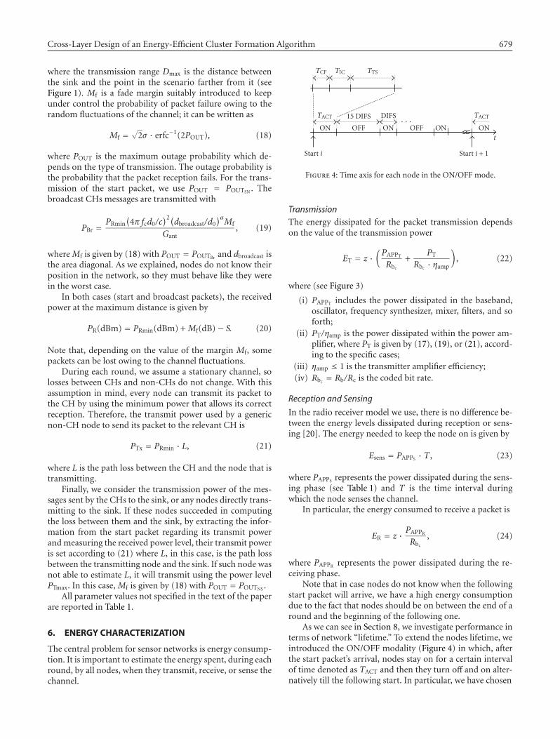
TCF TIC TTS
TACT
ON
15 DIFS DIFS
OFF ON OFF ON
TACT
ON· · ·
Figure 4: Time axis for each node in the ON/OFF mode.
TransmissionThe energy dissipated for the packet transmission dependson the value of the transmission power
ET = z ·(PAPPTRbc
+PT
Rbc · ηamp
), (22)
where (see Figure 3)
(i) PAPPT includes the power dissipated in the baseband,oscillator, frequency synthesizer, mixer, filters, and soforth;
(ii) PT/ηamp is the power dissipated within the power am-plifier, where PT is given by (17), (19), or (21), accord-ing to the specific cases;
(iii) ηamp ≤ 1 is the transmitter amplifier efficiency;(iv) Rbc = Rb/Rc is the coded bit rate.
Reception and Sensing
In the radio receiver model we use, there is no difference be-tween the energy levels dissipated during reception or sens-ing [20]. The energy needed to keep the node on is given by
Esens = PAPPS · T , (23)
where PAPPS represents the power dissipated during the sens-ing phase (see Table 1) and T is the time interval duringwhich the node senses the channel.
In particular, the energy consumed to receive a packet is
ER = z · PAPPRRbc
, (24)
where PAPPR represents the power dissipated during the re-ceiving phase.
Note that in case nodes do not know when the followingstart packet will arrive, we have a high energy consumptiondue to the fact that nodes should be on between the end of around and the beginning of the following one.
As we can see in Section 8, we investigate performance interms of network “lifetime.” To extend the nodes lifetime, weintroduced the ON/OFF modality (Figure 4) in which, afterthe start packet’s arrival, nodes stay on for a certain intervalof time denoted as TACT and then they turn off and on alter-natively till the following start. In particular, we have chosen

680 EURASIP Journal on Wireless Communications and Networking
(i) the duration of the ON phase equal to DIFS,(ii) the duration of the OFF phase equal to 15 ·DIFS,
according to suitable considerations, not reported for thesake of conciseness.
To be sure that a start packet is detected by each noderegardless of the ON/OFF mechanism, the sink must trans-mit sixteen sequential starting packets so that every node isable to receive at least one of these. Note that this requiresthat the sink has no energy consumption problems. Throughthis modality, we obtain a significant improvement of perfor-mance in terms of system lifetime.
As mentioned in Section 3, TACT is divided in the threeperiods of duration TCF, TIC, and TTS.
7. CROSS-LAYER DESIGN
7.1. Scenario 1—CLD v1
To improve network performance, we introduce a modi-fied version of LEACH B+ v1, based on the CL paradigm,denoted as CLD v1, where interactions between physicaland MAC layers and MAC and network layers are intro-duced.
For the interaction between physical and MAC layers, apower control algorithm is proposed which accounts for thenumber of retransmissions required. As mentioned, whennodes, either CHs or non-CHs, do not know the loss be-tween themselves and the sink, they transmit with a highpower level (obtained by assuming that the node is at a dis-tance Dmax from the sink). Since in this case nodes waste alot of energy, we impose that they transmit to the sink byusing a power equal to PTmax/2, while they use PTmax whenthey receive a retransmission request by the sink. In this way,the MAC layer affects the physical layer, namely the transmitpower algorithm.
Concerning the CL interactions between the MAC andnetwork layers, we use, once again, the number of retrans-missions requested to influence the CH election algorithmfor the following rounds. In Section 3.1, we stated that thevalue of N̂ used by a node p, N̂p, is decreased by 1 when theenergy dissipated by the node the last time it assumed the roleof CH is larger than ECH-sup, and it is increased by 1 when theenergy spent is less than ECH-inf. A possible CL interaction toreduce the energy waste consists in increasing and decreasingN̂p, by considering not only the energy dissipated, but alsothe number of retransmissions requested by the sink to a CHin the last round it assumed the role of CH. In particular, N̂p
is increased when the energy spent is low and the nodes havereceived less than 2 retransmission requests from the sink; atthe opposite, N̂p is decreased when the CH has dissipated alot of energy and has received more than 3 retransmissionrequests. By increasing N̂p, the probability that the node willbe CH for the next rounds increases and, in this way, this op-portunity is given only to nodes that are in a good locationwith respect to the sink, either in terms of energy expense, orin terms of collisions.
Table 2: Round when the first node expires.
LEACH B LEACH B+ v1
Nodes Nround/Joule Nround/Joule
30 16949 37284
25 22560 41985
20 29480 45143
15 32370 48205
10 42680 51550
5 48410 59375
0 56150 63900
7.2. Scenario 2—CLD v2
In this case, as stated previously, we assume that the loss be-tween two nodes remains unchanged for two rounds; a suit-able protocol design can take advantage of this. We definehere a new version of LEACH B+, namely CLD v2, which in-cludes all the techniques already introduced in CLD v1 plussome additional features: the information about the requestof retransmissions obtained at the first of the two rounds isused at the second round to change the structure of the clus-ter. At the first round, in fact, every non-CH node recordsthe value of the loss between itself and the sink and the totallosses between itself and the sink, passing through the CHs.At the beginning of the second round, if it has received one ormore retransmission requests, it changes the cluster to whichit belongs to. It will choose the CH, or also the sink, whichcorresponds to the smallest loss, avoiding the previous CHconsidered. No adaptive strategy is performed between thesecond and the third rounds, for example, because, owing tothe fact that the channel changes, in the third round, there isa new election of the CH nodes and new clusters are formed.
Moreover, when a non-CH node belonging to a certaincluster receives a retransmission request from its CH, to re-duce the packet losses, it transmits its packet directly to thesink, without passing through the CH. So, nodes can changethe cluster they belong to according to the number of retrans-missions that occurred within the cluster. However, the directtransmissions to the sink are very energy expensive, in partic-ular for those nodes that are farther from the sink, so this CLprotocol, even if advantageous in terms of packet loss rate, isexpected to worsen network lifetime.
8. NUMERICAL RESULTS
We show the performance results obtained by means of asimulator implemented on an OMNET++ platform [22]. Allsimulation parameters related to a network with M = d =100mt are reported in Table 1. All values of time intervalsare normalized with respect to TR; so, for example, tACT isequal to TACT/TR, and so forth.
8.1. Improvement with respect to LEACH B
First of all, in Table 2, we compare the round when the firstnode expires for LEACH B [18] and the new LEACH B+ v1

Cross-Layer Design of an Energy-Efficient Cluster Formation Algorithm 681
76543×104
35
30
25
20
15
10
5
0
Numberof
nod
esstill
alive
Nround/Joule
LEACH B+ v1CLD v1
Figure 5: Number of nodes still alive as a function of the numberof rounds, normalized with respect to energy.
protocol by showing the clear improvement provided by ourproposal. Note that in Table 2 as well as in the following fig-ures, the value of the number of rounds is normalized withrespect to the value of energy which equipped the sensorsinitially.
8.2. Scenario 1
In this section, we illustrate a comparison between the per-formance obtained in scenario 1 with the LEACH B+ v1 pro-tocol and with CLD v1 (i.e., without or with CL approachimplemented, resp.).
In Figure 5, we compare the network lifetime of the twoprotocols, considering a network ofNTOT = 30 nodes. In par-ticular, we show the number of nodes still alive as a functionof time, expressed in terms of number of rounds. The figureshows that the CL approach allows an increase of networklifetime. In Figure 6, we show the round when the first nodeexpires, as a function ofNTOT; this parameter increases by in-creasingNTOT. As we can notice, the improvement due to theCL approach is kept even by varying NTOT (i.e., the densityof nodes).
Now, we consider the packet losses. The causes for theselosses are the following.
(1) Fading: when PR < PRmin, the packet is lost; the mar-gin Mf is set in order to control the packet loss probabilityon each link, but the total packet loss rate in the network isdifferent, as it is a combination of the events on the differentlinks.
(2) Collisions: notwithstanding the use of a retransmis-sion mechanism, some packets could be lost. In fact, when anode transmits, it is not able to perceive a packet directed toitself, so it cannot ask for retransmission.
In Figure 7, we show the packet loss rate as a function ofNTOT for the two protocols. The losses increase, by increasing
5040302010
×103 47
44
41
38
35
32
Rou
ndatwhichthefirstnod
edies
NTOT
LEACH B+LEACH B+ with CLDSL
Figure 6: Round when the first node expires as a function of NTOT.
NTOT, owing to the larger traffic. As we can see, the two pro-tocols have about the same values of packet loss rate, so wecan conclude that CLD v1 improves network lifetime with-out increasing the packet loss rate.
Finally, in Figure 8, we show the round when the firstnode expires as a function of
β = PAPPSPAPPR
(25)
to show that there is a strong dependence between networklifetime and the power spent in the sensing state. In fact, inour protocol, the time during which sensors are in a sens-ing state is high, so if in this state they spend the same en-ergy as in the receiving state (β = 1), their life will be muchshorter.
8.3. Scenario 2
This section is dedicated to show the comparison betweenLEACH B+ v2 and CLD v2.
Concerning network lifetime (see Figure 9), LEACH B+v2 performs better than v1, because, in the former case, CHnodes have to transmit half of the broadcast packets than inthe latter. However, when we introduce the CL strategy de-scribed in Section 7.2, we have a decrease of network life-time, owing to the fact that we increase the number of di-rect transmissions to the sink, which are very expensive. Thisprotocol, however, allows a significant decrease of packet lossrate (see Figure 10) either with respect to LEACH B+ v1 orv2. So, in this scenario, the CL approach proposed, account-ing for MAC protocol status at network level, provides ad-vantages in terms of loss rate at the expense of energy effi-ciency.

682 EURASIP Journal on Wireless Communications and Networking
5040302010
0.1
0.08
0.06
0.04
0.02
0
Packetlossrate
NTOT
LEACH B+ v1CLD v2
Figure 7: Packet loss rate as a function of NTOT.
10.80.60.40.20
×103 55
50
45
40
35
30
Rou
ndatwhichthefirstnod
edies
β
LEACH B+ v1CLD v1
Figure 8: Round when the first node dies as a function of β.
9. CONCLUSIONS
In this paper, a CSMA-based WSN composed of several tensof nodes uniformly distributed over a square area is ana-lyzed by means of simulations taking into account the com-plete stack of layers. We proposed four different versionsof LEACH B+, a new protocol presented here which out-performs the other algorithms belonging to the same class(LEACH), previously presented in the literature. LEACH B+is a hybrid protocol which allows nodes to use a single-or two-hop path towards the sink according to energy-
9876543×104
35
30
25
20
15
10
5
0
Numberof
nod
esstill
alive
Nround/Joule
LEACH B+ v1LEACH B+ v2CLD v2
Figure 9: Number of nodes still alive as a function of the numberof rounds, normalized with respect to the energy.
5040302010
0.1
0.08
0.06
0.04
0.02
0
Packetlossrate
NTOT
LEACH B+ v1LEACH B+ v2CLD v2
Figure 10: Packet loss rate as a function of NTOT.
related considerations. Moreover, the distributed algorithmfor cluster-head self-election has been suitably designedstarting from some novel analytical descriptions of the en-ergy spent on the average at each round; this model was re-ported in the appendix to make easier reading of the paper.
We introduced the CL paradigm, which is shown here toimprove performance. In particular, we focused on two dif-ferent scenarios, characterized by two different values of theratio between TR and Tcoh. The two different CL approaches,derived from the two scenarios, allow the improvement of

Cross-Layer Design of an Energy-Efficient Cluster Formation Algorithm 683
the network lifetime (scenario 1) or the packet loss rate (sce-nario 2).
The paper jointly takes routing, MAC, physical, energy,and propagation aspects into account, and this makes thedescription of the model used rather complex. Owing tothe many parameters of the model, the results shown rep-resent a sample among the many found by the authors, but itwas found out that the conclusions drawn can be consideredmore general and applicable to other sets of input parame-ters.
APPENDICES
A. COMPUTATIONOF N̂
N̂ is chosen in order to minimize the total transmission en-ergy, which is the sum of the energies dissipated by eachnode, CH and non-CH, in a round.
We assumed that there are NTOT nodes distributed uni-formly in an M ×M region. If N̂ nodes became CHs, therewould be N̂ + 1 clusters, because we consider also the clusterformed by nodes which transmit directly to the sink. For thepurpose of the determination of N̂ , we assume that all N̂ + 1clusters are equally loaded, so in every cluster, there are onaverage NTOT/(N̂ + 1) nodes (one CH and NTOT/(N̂ + 1)− 1non-CH nodes).
The total energy spent in a round is given on the averageby
ETOT = ECH · N̂ + Enon-CH→CH ·Nnon-CH→CH
+ Enon-CH→S ·Nnon-CH→S,(A.1)
where
(i) ECH is the energy dissipated by each CH;(ii) Enon-CH→CH is the energy dissipated by each non-CH
which chooses a CH to transmit to and
Nnon-CH→CH = N̂ ·(NTOT
N̂ + 1− 1)
(A.2)
is the total average number of non-CHs which trans-mit to a CH;
(iii) Enon-CH→S is the energy dissipated by each non-CHwhich chooses to transmit to the sink and
Nnon-CH→S = NTOT
N̂ + 1(A.3)
is the number of non-CHs which transmit directly tothe sink, on the average.
Each CH dissipates energy to send the broadcast packetto transmit its own packet and the packets of the other nodesto the final sink and to make sensing (the energy spent toreceive packets can be neglected). We assume an averagesituation where the shadowing is not considered and we
suppose that there are not collisions in the system, thus wedo not consider the energy dissipated for the retransmissions.Hence, the transmission energy dissipated by a CH at a givenround, on average, can be written as
ECH =(NTOT
N̂ + 1− 1)(
EAPPT + b d αCH-S
)︸ ︷︷ ︸
Non-CH packets
+(EAPPT + b d α
CH-S
)︸ ︷︷ ︸Own packet
+(EAPPT + b d α
broadcast
)︸ ︷︷ ︸Broadcast packet
+(PAPPS · T
)︸ ︷︷ ︸Sensing
,
(A.4)
where dCH-S is the distance between the CH and the externalsink, dbroadcast is the distance between the CH and the farthestpoint of the observed area, EAPPT = z PAPPT /Rbc is the energyspent by the block APPT during a packet transmission, and bis a constant that takes into account transmission parametersfc, Gant, PRmin, and so forth, according to (17). Finally, T isthe sensing period, which is set to TACT. So, contrary to theLEACH B protocol, we take into consideration also the en-ergy spent for sensing, obtaining a more realistic evaluationof N̂ .
Each non-CH node only has to transmit its packet to theCH or to the sink and so the energy dissipated for each roundis
Enon-CH→CH = EAPPT + b dα
p-CH + PAPPS · T , (A.5)
where dp-CH is the distance between the pth node and theCH. Moreover,
Enon-CH→S = EAPPT + b dα
p-S + PAPPS · T , (A.6)
where dp-S is assumed equal to Dmax, which represents theworst case.
In many practical scenarios, the energy spent in the blockAPPT in (A.4), (A.5), and (A.6) can be neglected, that is,EAPPT � bDα for every distance D.
As developed in [10], the expected squared distance froma general node p to the CH is given on average by
E[d2p-CH
]= M2
2πN̂, (A.7)
so that (A.5) can be approximated by
Enon-CH→CH � PAPPS · T + b
(M√2πN̂
)α
. (A.8)

684 EURASIP Journal on Wireless Communications and Networking
Therefore, for each round, the total transmission energydissipated in the network is on average
ETOT =N̂(NTOT
N̂ + 1bD α
max + b d αbroadcast + PAPPST
)
+ N̂(NTOT
N̂ + 1− 1)·(PAPPST + b
(M√2πN̂
)α)
+NTOT
N̂ + 1·(PAPPST + bD α
max
);
(A.9)
however, considering that N̂ � NTOT and 1� N̂ , (A.9) canbe approximated as
ETOT = N̂ · (b d αbroadcast + PAPPS · T
)+NTOT
N̂
(bD α
max + PAPPS · T)
+NTOT b
(M√2πN̂
)α
+ K ,
(A.10)
where K is a term that does not depend on N̂ . At this point,the optimum number of CHs can be evaluated easily by set-ting the derivative of ETOT performed with respect to N̂ tozero. We obtain
N̂2 · k0 = N̂1−α/2 · k1 + k2, (A.11)
where
k0 = b d αbroadcast + PAPPST ,
k1 = NTOT b α
2
(M√2π
)α,
k2 = NTOTPAPPST +NTOT bDα
max .
(A.12)
This equation can be solved only numerically. Note that eachnode can determine its own optimumnumber of CHs, owingto the fact that the values of the total number of nodes inthe network, the path loss exponent, the network size, thedistance considered in the transmission of broadcast packets,and TACT are contained in the trigger transmitted by the sink,so they are known by nodes. Note that N̂ does not dependon the distance between the CH and the final sink, so thatdistance could not be known.
REFERENCES
[1] I. F. Akyildiz, W. Su, Y. Sankarasubramaniam, and E. Cayirci,“A survey on sensor networks,” IEEE Commun. Mag., vol. 40,no. 8, pp. 102–114, 2002.
[2] V. Rajaravivarma, Y. Yang, and T. Yang, “An overview of wire-less sensor network and applications,” in Proc. 35th Southeast-ern Symposium on System Theory (SSST ’03), pp. 432–436,Morgantown, WVa, USA, March 2003.
[3] M. Tubaishat and S. Madria, “Sensor networks: an overview,”IEEE Potentials, vol. 22, no. 2, pp. 20–23, 2003.
[4] C.-Y. Chong and S. P. Kumar, “Sensor networks: evolution,opportunities, and challenges,” Proc. IEEE, vol. 91, no. 8,pp. 1247–1256, 2003.
[5] X. Hong, K. Xu, and M. Gerla, “Scalable routing protocols formobile ad hoc networks,” IEEE Network, vol. 16, no. 4, pp. 11–21, 2002.
[6] P. Chen, B. O’Dea, and E. Callaway, “Energy efficient systemdesign with optimum transmission range for wireless ad hocnetworks,” in Proc. IEEE International Conference on Commu-nications (ICC ’02), vol. 2, pp. 945–952, New York, NY, USA,April–May 2002.
[7] A.Woo andD. Culler, “A transmission control scheme forme-dia access in sensor networks,” in Proc. ACM/IEEE Interna-tional Conference on Mobile Computing and Networking (Mo-biCom ’01), pp. 221–235, Rome, Italy, July 2001.
[8] S. Lindsey, C. Raghavendra, and K. M. Sivalingam, “Datagathering algorithms in sensor networks using energy met-rics,” IEEE Trans. Parallel Distrib. Syst., vol. 13, no. 9, pp. 924–935, 2002.
[9] W. B. Heinzelman, A. P. Chandrakasan, and H. Balakrishnan,“Energy-efficient routing protocols for wireless microsensornetworks,” in Proc. 33rd Hawaii International Conference onSystem Sciences (HICSS ’00), pp. 1–10, Maui, Hawaii, USA,January 2000.
[10] W. B. Heinzelman, A. P. Chandrakasan, and H. Balakrishnan,“An application-specific protocol architecture for wireless mi-crosensor networks,” IEEE Transactions onWireless Communi-cations, vol. 1, no. 4, pp. 660–670, 2002.
[11] M. J. Handy, M. Haase, and D. Timmermann, “Low energyadaptive clustering hierarchy with deterministic cluster-headselection,” in Proc. 4th International Workshop on Mobile andWireless Communications Network (MWCN ’02), pp. 368–372,Stockholm, Sweden, September 2002.
[12] A. Conti and D. Dardari, “The effects of nodes spatial distri-bution on the performance of wireless sensor networks,” inProc. IEEE 59th Vehicular Technology Conference (VTC ’04),vol. 5, pp. 2724–2728, Milan, Italy, May 2004.
[13] R. Verdone, “An energy-efficient decentralised communica-tion protocol for a network of uniformly distributed sensorspolled by a wireless transceiver,” in Proc. IEEE InternationalConference on Communications (ICC ’04), vol. 6, pp. 3491–3498, Paris, France, June 2004.
[14] Y. Zhang and L. Cheng, “Cross-layer optimization for sensornetworks,” in Proc. New YorkMetro Area NetworkingWorkshop(NYMAN ’03), New York, NY, USA, September 2003.
[15] M. Conti, G. Maselli, G. Turi, and S. Giordano, “Cross-layering in mobile ad hoc network design,” IEEE Computer,vol. 37, no. 2, pp. 48–51, 2004.
[16] A. Safwat, H. Hassanein, and H. Mouftah, “Optimal cross-layer designs for energy-efficient wireless ad hoc and sen-sor networks,” in Proc. IEEE 22nd International Performance,Computing, and Communications Conference (IPCCC ’03), pp.123–128, Phoenix, Ariz, USA, April 2003.
[17] L.-C. Wang and C.-W. Wang, “A cross-layer design of cluster-ing architecture for wireless sensor networks,” in Proc. IEEEInternational Conference on Networking, Sensing and Con-trol (ICNSC ’04), vol. 1, pp. 547–552, Taipei, Taiwan, China,March 2004.
[18] A. De Pedri, A. Zanella, and R. Verdone, “An energy efficientprotocol for wireless ad hoc sensor networks,” in Proc. Au-tonomous Intelligent Networks and Systems (AINS ’03), MenloPark, Calif, USA, June–July 2003.

Cross-Layer Design of an Energy-Efficient Cluster Formation Algorithm 685
[19] K. Sohrabi, J. Gao, V. Ailawadhi, and G. J. Pottie, “Protocolsfor self-organization of a wireless sensor network,” IEEE Pers.Commun., vol. 7, no. 5, pp. 16–27, 2000.
[20] W. Ye, J. Heidemann, and D. Estrin, “An energy-efficient MACprotocol for wireless sensor networks,” in Proc. 21st AnnualJoint Conference of the IEEE Computer and CommunicationsSocieties (INFOCOM ’02), vol. 3, pp. 1567–1576, New York,NY, USA, June 2002.
[21] C. Buratti, A. Giorgetti, and R. Verdone, “Simulation of an en-ergy efficient carrier sensing multiple access protocol for clus-tered wireless sensor networks,” in Proc. International Work-shop on Wireless Ad-Hoc Networks (IWWAN ’04), Oulu, Fin-land, June 2004.
[22] OMNeT++: Objective Modular Network Testbed in C++,http://www.omnetpp.org.
[23] IEEE 802.11, “Standard for Wireless LAN Medium AccessControl (MAC) and Physical Layer (PHY) Specifications,”IEEE Std 820.11-1997 edition, The Institute of Electrical andElectronics Engineers, New York, NY, USA, 1997.
[24] J. N. Al-Karaki and A. E. Kamal, “Routing techniques in wire-less sensor networks: a survey,” IEEE Wireless Communica-tions, vol. 11, no. 6, pp. 6–28, 2004.
[25] M. Chatterjee, S. K. Das, and D. Turgut, “WCA: a weightedclustering algorithm for mobile ad hoc networks,” ClusterComputing, vol. 5, no. 2, pp. 193–204, 2002, Special Issue onMobile Ad Hoc Networking.
[26] S. Basagni, “Distributed clustering for ad hoc networks,”in Proc. 4th International Symposium on Parallel Architec-tures, Algorithms, and Networks (I-SPAN ’99), pp. 310–315, Perth/Fremantle, Western Australia, Australia, June1999.
[27] J. G. Proakis, Digital Communications, McGraw-Hill, NewYork, NY, USA, 3rd edition, 1995.
Chiara Buratti was born in Ravenna, Italy,on October 30, 1976. She received the M.S.degree (summa cum laude) in telecommu-nication engineering from the University ofBologna, Italy, in 2003. Her research inter-est is on wireless sensor networks, with par-ticular attention to MAC, routing, and con-nectivity issues, but she is also interested inBluetooth and ZigBee networks. Since 2003,she has been involved in Network of Excel-lence in Wireless COMmunications (NEWCOM), the NoE bornwithin the Sixth Framework Program of the EC, and, in particu-lar, she has been working on Project A, dedicated to wireless ad hocand sensor networks.
Andrea Giorgetti was born in Cesena, Italy,on November 5, 1974. He received the Lau-rea degree in electronic engineering (withhonors) and the Ph.D. degree in electronicengineering and computer science from theUniversity of Bologna, Bologna, Italy, in1999 and 2003, respectively. In 2003, hejoined IEIIT-BO/CNR where he became aresearcher in 2005. His research interests in-clude ultra-wideband systems, wireless sen-sor networks, and MIMO systems. He is a Member of IEEE.
Roberto Verdone was born in Bologna,Italy, in 1965. He received the Laurea de-gree in electronic engineering (with honors)and the Ph.D. degree in electronic engineer-ing and computer science from the Univer-sity of Bologna, Bologna, Italy, in 1991 and1995, respectively. From 1996 to 2001, hewas a researcher with the Centre for Stud-ies in Computer Science and Telecommu-nication Systems of the National ResearchCouncil (CSITE-CNR), University of Bologna, studying telecom-munications. Since November 2001, he has been a Full Professor oftelecommunications with the University of Bologna. His researchactivity is concerned with digital transmission, cellular and mo-bile radio systems, wireless local area networks, wireless sensor net-works, and intelligent transportation systems. From 1997 to 2000,he participated in COST259 activities and acted as a coauthor ofthe COST259 Final Report. He is the Chairman of the WG on net-work aspects within the followup action COST273, and he is a Na-tional Delegate for the action. He is a Member of IEEE and Exec-utive Board Member of NEWCOM, the Network of Excellence inWireless COMmunications funded by EC through FP6.