Embed Size (px)
Citation preview

Critical Thickness of Rupture of Foam Films in Relation to the Acting Surface Forces
measurements: critical thickness of film ruptureair
airair
water waterhydrophobic attraction
very low surfactantconcentration
P. Kralchevsky, K. Danov, J. Angarska, B. Dimitrova, K. P. Ananth, Alex Lips
University of Sofia (BG), University of Shumen (BG), Unilever Research (USA)
Basic Idea: The air is “hydrophobic phase” ⇒ Hydrophobic attraction could be present in foam films ⇒ It would affect the critical thickness of film rupture!
1
(Invited Lecture at the Conference “EUFOAM”, Marne la Vallée, France, July 5-8, 2004)
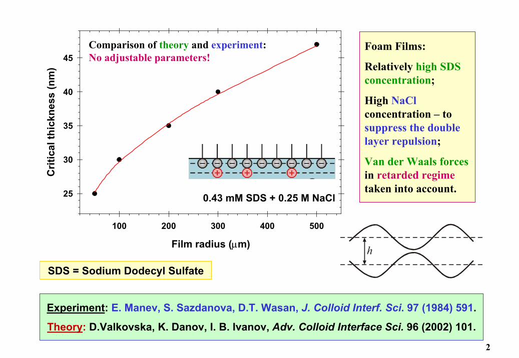
Film radius (µm)
100 200 300 400 500
Crit
ical
thic
knes
s (n
m)
25
30
35
40
45
0.43 mM SDS + 0.25 M NaCl
Comparison of theory and experiment: No adjustable parameters!
Foam Films:
Relatively high SDS concentration;
High NaClconcentration – to suppress the double layer repulsion;
Van der Waals forcesin retarded regimetaken into account.
Experiment: E. Manev, S. Sazdanova, D.T. Wasan, J. Colloid Interf. Sci. 97 (1984) 591.
Theory: D.Valkovska, K. Danov, I. B. Ivanov, Adv. Colloid Interface Sci. 96 (2002) 101.
h
SDS = Sodium Dodecyl Sulfate
2

Theory: D.Valkovska, K. Danov, I. B. Ivanov, Adv. Colloid Interface Sci. 96 (2002) 101:
Assumptions:
1. Simultaneous film drainage and growth of interfacial perturbations;
2. The critical wave has amplitude = h/2;
3. Unbounded waves: Hankel transformation: ∫∞
=0
0 )(),(),( kdkkrJtkAtr ξζ
),(
)()exp( 0
khYhV
krJt
=
∝
ω
ωζ
ω < 0 ⇒ the wave will decay (stable film);
ω > 0 ⇒ the wave will grow (unstable film);
ω = 0 ⇒ transition from stability to instability.
film
air
air
h
z
ζ ∝ ( )J kr0λ
3
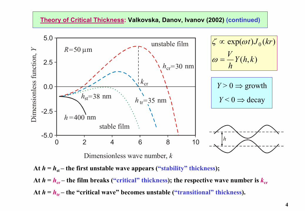
Theory of Critical Thickness: Valkovska, Danov, Ivanov (2002) (continued)
0-5.0
-2.5
5.0
2.5
0.0
2 10864
R=50 mµ
hst=38 nm
hcr=30 nm
h tr=35 nm
kcr
h =400 nmstable film
Dimensionless wave number, k
Dim
ensi
onle
ss fu
nctio
n, Y
unstable film
),(
)()exp( 0
khYhV
krJt
=
∝
ω
ωζ
At h = hst – the first unstable wave appears (“stability” thickness);
At h = hcr – the film breaks (“critical” thickness); the respective wave number is kcr
At h = htr – the “critical wave” becomes unstable (“transitional” thickness).
Y > 0 ⇒ growth
Y < 0 ⇒ decay
h
4

Critical Thickness, Basic Equations: Valkovska, Danov, Ivanov (2002)
∫∫ Π−Π′
=Π−
tr
cr
tr
cr c
3
c
6
3cr
2
2cr h
h
h
hdh
Phdh
Ph
hRk σ
3cr
2
2cr
3tr
trc4tr
3cr
tr 2)]([
24)(
hRkh
hPhh
hσ
+Π−=Π′
)32
exp()( tr
cr c
3
3cr
2cr
tr4/1
B
2tr
cr ∫ Π−Π′
−=h
hdh
Ph
hk
hTkh
hσ
Three equations for determining hcr, kcr and htr
Numerical solution: Bisection method
Single roots: convenient computations
Input Quantities:
R – Film radius; Pc – Capillary pressure; σ – Surface tension; T – temperature
Disjoining pressure: Π(h) = Πvw(h) + Πhb(h) (van der Waals + hydrophobic)
5

Physical Origin of the Hydrophobic Surface Force
Two kinds of hydrophobic surface forces:
(1) Due to gaseous capillary bridges (cavitation) between
the hydrophobic surfaces
(2) Due to hydrogen-bond-propagated ordering of water molecules in the vicinity of
hydrophobic surfaces
Ordered H2O in the film, Disordered H2O in the bulk ⇒ Gain of Entropy !
Eriksson, J. C. et al. J. Chem. Soc. Faraday Trans. 2 1989, 85, 163.
gas water
gas bridge betweentwo hydrophobic surfaces
water
hydrophobicinterface
bulk
Yushchenko et al., J. Colloid Interface Sci. 96
(1983) 307
6
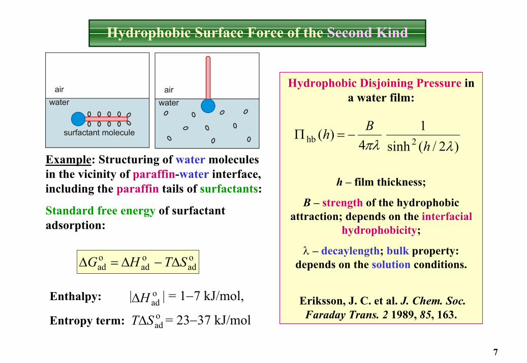
Hydrophobic Surface Force of the Second Kind
Hydrophobic Disjoining Pressure in a water film:
h – film thickness;
B – strength of the hydrophobic attraction; depends on the interfacial
hydrophobicity;
λ – decaylength; bulk property: depends on the solution conditions.
Eriksson, J. C. et al. J. Chem. Soc. Faraday Trans. 2 1989, 85, 163.
Example: Structuring of water molecules in the vicinity of paraffin-water interface, including the paraffin tails of surfactants:
Standard free energy of surfactant adsorption:
oad
oad
oad STHG ∆−∆=∆
Enthalpy: | | = 1−7 kJ/mol,
Entropy term: = 23−37 kJ/mol
oadH∆oadST∆
)2/(sinh1
4)( 2hb λπλ h
Bh −=Π
water
surfactant molecule
air
waterair
7
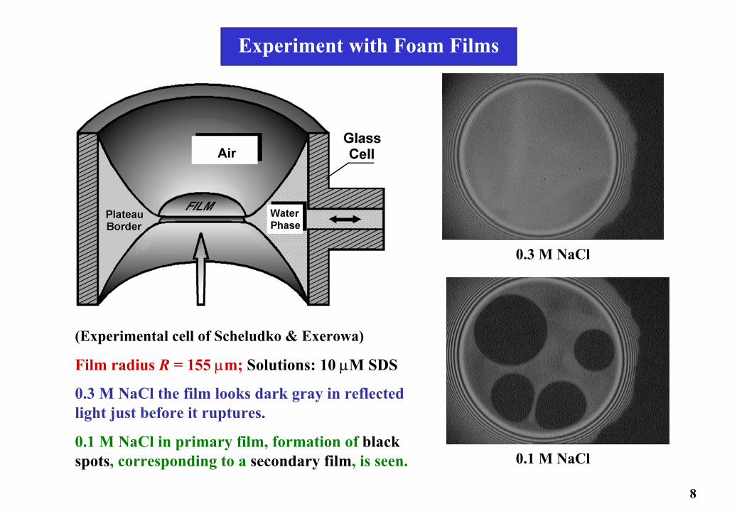
Experiment with Foam Films
0.3 M NaCl
0.1 M NaCl
(Experimental cell of Scheludko & Exerowa)
Film radius R = 155 µm; Solutions: 10 µM SDS
0.3 M NaCl the film looks dark gray in reflected light just before it ruptures.
0.1 M NaCl in primary film, formation of black spots, corresponding to a secondary film, is seen.
Air
8

At 0.3 M NaCl – the electrostatic effects are suppressed: working concentration!
No equilibrium films – only the critical thickness of film rupture is measured.
dzz
zhzhnnnnhhAji
ji ∫∞
+−+
+
−=
0222/322
222eP
)21()~2exp()~21(
)()(
43)(
πν
3vw 6)()(hhAh
π−=Π
Πvw – only dispersion interactionwith account for the electro-magnetic retardation effect (Russel et al):
At 0.1 M NaCl – indications about existence of primary films and Πel are seen.
9
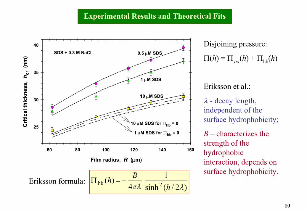
Experimental Results and Theoretical Fits
Film radius, R (µm)
60 80 100 120 140 160
Crit
ical
thic
knes
s, h
cr (
nm)
25
30
35
40SDS + 0.3 M NaCl 0.5 µM SDS
1 µM SDS
10 µM SDS
10 µM SDS for Πhb = 0
1 µM SDS for Πhb = 0
Disjoining pressure:
Π(h) = Πvw(h) + Πhb(h)
Eriksson et al.:
λ - decay length, independent of the surface hydrophobicity;
B – characterizes the strength of the hydrophobic interaction, depends on surface hydrophobicity.
)2/(sinh1
4)( 2hb λπλ h
Bh −=ΠEriksson formula:
10

Parameter Values
System λ (nm) B (mJ/m2)
0.5 µM SDS + 0.3 M NaCl 15.85 6.56 × 10⁻⁴
1.0 µM SDS + 0.3 M NaCl 15.85 4.71 × 10⁻⁴
10 µM SDS + 0.3 M NaCl 15.85 3.34 × 10⁻⁵
DDOA-covered mica* 15.8 0.6
F-surfactant-covered mica* 15.8 0.9
*Data by Eriksson et al. DDOA = dimethyl-dioctadecyl-ammonium bromide; λ is constant; B decreases with the rise of SDS concentration
11
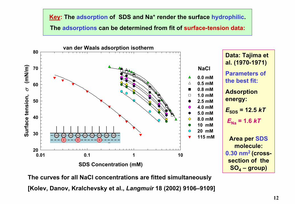
Key: The adsorption of SDS and Na+ render the surface hydrophilic.
The adsorptions can be determined from fit of surface-tension data:
SDS Concentration (mM)
0.01 0.1 1 10
Surf
ace
tens
ion,
σ
(mN
/m)
20
30
40
50
60
70
80
0.0 mM0.5 mM0.8 mM1.0 mM2.5 mM4.0 mM5.0 mM8.0 mM10 mM20 mM115 mM
NaCl
van der Waals adsorption isothermData: Tajima et al. (1970-1971)
Parameters of the best fit:
Adsorption energy:
ESDS = 12.5 kT
ENa = 1.6 kT
Area per SDSmolecule:
0.30 nm2 (cross-section of the SO4 – group)
The curves for all NaCl concentrations are fitted simultaneously
[Kolev, Danov, Kralchevsky et al., Langmuir 18 (2002) 9106–9109]12

CSDS(µM)
Γ1 / Γ∞(%)
Γ2 / Γ∞(%)
EG(mN/m)
0.5 4.2 % 1.0 % 0.560
1.0 6.9 % 2.1 % 0.921
10.0 33.2 % 19.4 % 6.15
Results from the fit of the SDS surface tension isotherms:
Γ1 – surfactant (DS–) adsorption;
Γ2 – counterion (Na+) adsorption;
Γ∞ – maximal adsorption in a closely-packed surfactant adsorption monolayer;
EG – surface dilatational (Gibbs) elasticity.
air
air
Na
Na
air
water waterhydrophobic attraction
surfactant
13
(0.3 M NaCl)

Foam filmsSDS + 0.3 M NaCl
Inverse ionic adsorption, (Γ0 + Γ1 + Γ2)−1 (m2/µmol)
0.0 0.5 1.0 1.5 2.0 2.5 3.0
Para
met
er B
(10
−4 m
J/m
2 )
-2
0
2
4
6
8
10
Slope:2.74 ± 0.16 (10−13 J.mol.m−4)
Plot of B vs. (Γ0 + Γ1 + Γ2)−1;
Γ0, Γ1 and Γ2 are the adsorptions of OH−, DS− and Na+ ions
(the adsorbed ions render the air-water interface hydrophilic)
14
Conclusions
1. The van der Waals attraction, alone, is insufficient to explain the results, especially for the lower SDS concentrations, 0.5 and 1 µM.
2. If the difference is attributed to the hydrophobic attraction, then a very good agreement between theory and experiment is achieved.
3. From the best fit, we determine decaylength λ ≈ 15.8 nm, which coincides with results by other authors for hydrophobized mica surfaces.
4. The strength of the hydrophobic interaction, B, is found to be inversely proportional to the surface density of the adsorbed ions.
5. With the decrease of SDS adsorption, greater areas of bare hydrophobic air-water interface are uncovered ⇒ hydrophobic attraction becomes stronger.
Details can be found in: Langmuir 20 (2004) 1799.
15