Embed Size (px)
Citation preview
JAIC 1987, Volume 26, Number 2, Article 1 (pp. 65 to 73)
CRITERIA FOR TREATMENT: REVERSIBILITY
Barbara Appelbaum
ABSTRACT—The author reconsiders the “Principle of Reversibility” by clarifying its definition and by examining the variables that make a treatment reversible. Different criteria for different parts of a treatment are recommended. The relationship between cleaning and reversibility is examined. There are degrees of reversibility; even irreversible treatments should be considered in terms of whether they allow for future treatment (“re-treatability”).
The “Principle of Reversibility”1 is one of the basic tenets of the modern field of conservation. The Code of Ethics of the American Institute for Conservation, however, was written mainly with the treatment of paintings in mind. Clearly, varnishing and inpainting are expected to be reversible processes. And, when the Code was written in the 1960s, wax linings were such an improvement over glue linings that we can assume that the reversibility of the lining process was not considered in any way problematic.
Reversibility is still a major criterion of good conservation treatment, one that sets conservators apart from skilled restorers or repairers. The “Principle of Reversibility” is one of the factors which establish our unique intent to project our work into the distant future. Conservators have an obligation to assure to the best of their ability that the condition of an object remain unchanged long after treatment is completed. Knowledge of how conservation materials age, how they interact with the object, and how the object responds to its environment is therefore necessary to fulfill this obligation.
Since the Code was promulgated, there has been little discussion about the meaning of reversibility in relation to treatments other than those of paintings, although the principles in the Code have since been applied to the treatment of a much wider range of materials, including machinery and whole buildings. The range of treatment materials and techniques has also expanded tremendously. It is important, therefore, to examine the idea of reversibility in relation to all parts of a treatment, to many different kinds of objects, and to a wide variety of treatment techniques.
“Reversibility” is often used inaccurately as a catch-all term for a variety of treatment criteria. These include such varied issues as the appropriateness of a treatment material to the aesthetic requirements of the object and the compatibility of a treatment material to the physical requirements of the object. More precise and sophisticated terminology is necessary to produce more realistic evaluations of conservation treatments.
1
1 TERMINOLOGY
In order to be as clear as possible about the meaning of the term “reversible,” it is important that conservators confine its use to the description of a process rather than of a material. The idea that a material can be reversible is not logical. The incorrect use of “reversibility” to mean “solubility” as applied to resins has however become common. It is certainly tempting to refer to a material like Acryloid¯B-72, for example, as a “reversible material” in order to indicate a group of properties which we find desirable. These include chemical inertness, unchanging solubility over long periods of time, durability, and lack of color changes. However, the use of the term “reversibility” to cover all of these properties may produce serious error if it leads us to assume that any treatment using a soluble material is a reversible one, or that any use of an “approved” conservation material constitutes a proper treatment.
In order to avoid this confusion, I propose that Robert Feller's terminology for describing the photochemical stability of thermoplastic resins2 be put into common use and extended to other conservation materials. Acryloid¯B-72 and the polyvinyl acetate resins can then be referred to as Class A materials, with a useful lifetime of over one hundred years, polybutylmethacrylate (e.g., Elvacite¯ #2044) as a Class B material, with a useful lifetime of twenty to one hundred years, etc. This terminology is particularly meaningful because, unlike many terms we take from other fields, it describes our particular needs for long-term stability, requirements much more stringent than those of the industrial fields from which we appropriate materials.
In this paper, I shall reserve the term “reversibility” to denote the property of a treatment that allows a knowledgeable conservator to “turn back the clock” on a treatment. In functional terms, this does not require that the object be identical to what it was,3 only that we can return it to a state where our treatment choices are as broad as they were before the treatment in question was performed.
2 ANALYSIS OF A CONSERVATION TREATMENT
In order to clarify how reversibility relates to different parts of a treatment, it might be useful to divide treatment procedures into separate parts (these refer to the original treatment under question). These are given in the usual order of procedure: 1) cleaning, the removal of non-original materials either those accidentally deposited (i.e. dirt) or those applied purposely (varnish, inpaint, fillings); 2) disassembly, the separation of fragments, the removal of adhesive repairs, sewing, and mechanical constraints such as linings, patches, mounts, etc.; 3) internal consolidation of structural weakness, including impregnation, consolidation of interlayer cleavage, and the sizing of paper; 4) changes in original materials, as in the reduction of metals, bleaching, or sanding the reverse of canvas paintings; 5) repairs and reassembly, including adhesive
2
repairs, sewing, mechanical constraints such as linings, patches, and mountings; 6) additions, largely cosmetic, as in varnishing, fillings, compensation.
3 REVERSIBILITY AND CLEANING
Cleaning is obviously not reversible; the exact material removed cannot be replaced. It is therefore vital that the conservator be sure that the material being removed is not original to the maker of the piece or important to any historic use of it, or that any information that such material can provide is not lost during the process. Cleaning of archaeological bronzes or ethnographic materials must be considered carefully before significant material is removed. However, once it is ascertained that the materials being removed are not a purposeful addition by the artist or user, the cleaning does not detract from the integrity of the piece. If there is a possibility that the removed material might at some time be analyzed to provide information about the history of the piece, it can be saved. Cleaning does not necessarily destroy information.
Even though cleaning is not technically reversible, the capability of reversing the visual effect can be important. An argument of the partial and selective cleaners4 in the recurring controversy on the cleaning of paintings is that varnish layers must not be completely removed so that a thin wash of discolored resin is left on the surface to harmonize color schemes which have become unbalanced because of the different rates of deterioration of the pigments. This is unnecessary, since cleaning is visually reversible, and the technical identity of the material being removed is unimportant as long as we are sure that it is not the artist's design layer. All discolored varnish which can be safely removed should be, since it will usually continue to cross-link or oxidize, causing additional color change and a decrease in solubility. Varnishing and inpainting of losses should be carried out before any decision can be made about the color balance of the painting. If, after an appropriate period of consideration, the color still seems inappropriate, a toned varnish can be applied to the whole or to parts of the painting. This process is actually a step in compensation. The use of a modern toned resin rather than the existing varnish for this purpose will provide less need for re-treatment, since the natural resin will continue to darken, while a Class A conservation material will retain exactly the color that is applied.
4 REVERSIBILITY, INTERNAL CONSOLIDATION, AND RE-TREATABILITY”
Even if an internal consolidant is easily soluble, it is unlikely that much can ever be removed, particularly since objects that need consolidation are by definition so weak that repeated applications of solvent may cause damage. Even if solvent vapors are used, the deeper the impregnant has penetrated, the less likely removal is.5 Even a minor treatment like injecting warm gelatin under loose flakes of paint is not reversible, as there is no physical access to
3
the gelatin lodged between the layers of paint after the paint is laid down. If internal consolidation with easily soluble materials will not be reversible in the future, then what criteria should be applied for the choice of material?
Impregnation is one example of a sometimes necessary but irreversible treatment. As with any treatment, impregnation must satisfy the requirements of aesthetic appropriateness and physical and chemical compatibility, but if it is irreversible upon completion of the treatment, reversibility during the course of the treatment must also be considered. Can drips or pools of impregnant be removed from the surface of the piece before the material sets? What can be done in the course of treatment to adjust the gloss of the surface? How much control is there over the appearance of the piece? What happens if the treatment does not proceed exactly as the conservator had expected?
An equally important question is: what will happen when the piece needs treatment again, particularly if the problem that necessitated the treatment recurs? Can the same treatment be repeated? Can a different material be used with the first one still in place? What can be done with written condition and treatment records to make it more likely that a future conservator can find out what was done? The undertaking of an admittedly irreversible treatment does not absolve the conservator of responsibility for the future of the object, but increases the importance of a factor we might call, for want of a more elegant term, “re-treatability.” The notion of re-treatability is one that is often more helpful in evaluating treatments than the idea of reversibility itself. This is particularly true in the impregnation of badly deteriorated materials, since the treatment strengthens what is left of the object but may not prevent further deterioration of original material, and re-treatment may not be far in the future.
5 CHANGES TO ORIGINAL MATERIAL
Obviously irreversible treatments like bleaching and structural changes in metals are, properly, subject to a great deal of controversy. An important issue in their use is the degree of predictability the conservator can bring to the choice of treatment methods and materials, and the amount of control that can be exercised in the course of treatment. Issues related to treatment techniques like these perhaps belong to specialists in the relevant conservation field; it is noteworthy, however, that many common conservation techniques (e.g. changes on the pH of paper, sanding the reverse of a canvas support for a painting, attempts to flatten wood panels, etc.) are beyond question irreversible, yet have not often been discussed in these terms.
6 DISASSEMBLY AND REASSEMBLY
Although mechanical additions like patches, mounts, and linings should be easily removable, for many objects durability may be a more important consideration. Joint failure in glass or ceramic objects could result in substantial additional damage to the piece, and reversibility may therefore be a
4
lesser consideration. Ease in undoing existing repairs may, however, depend on a lack of durability. We may be able to take apart old repairs, glue linings, etc., simply because they have become very weak. This is not an acceptable standard for modern conservators. Modern techniques should be both durable and reversible.
7 AESTHETIC ADDITIONS
In this area, the highest requirements for reversibility should be applied. Compensation and protective coatings should be easily removable without removing or weakening structural parts of a treatment.
8 CRITERIA FOR THE REMOVAL OF CONSERVATION MATERIALS
Once we have standards of reversibility for different parts of a treatment, by what means can we judge in advance the future removability of the materials we add? In order to establish a method for evaluating the reversibility of treatments, it would be interesting to try to define what makes the removal of added conservation materials possible. To a first approximation, these are the main points of consideration: 1) the solubility of the components of the piece under treatment; 2) the solubility of the conservation material; 3) the physical nature of their interface; 4) the amount of material to be removed. The theoretical relation between numbers (1), (2) and (3) is sometimes a simple one: in order to remove a material by dissolving it, it must be soluble in a solvent that does not soften the substrate, and it must be physically accessible to the solvent. Acryloid¯ B-72, for example, cannot be removed safely from an acrylic emulsion painting if the paint is soluble in the same solvents that dissolve the B-72.
The nature of the interface can be important apart from any question of solubility: if the bond between a coating layer and a substrate is weak, mechanical removal is possible, and sometimes preferable, regardless of the solubility of either material. This is the case with the removal of a deteriorated glue lining from the reverse of a canvas painting. In situations like this, putting the glue into solution is less desirable than mechanical removal, since the solution would penetrate the porous textile, from which it probably could not be removed. Another example where mechanical removal might be preferable is in the case of removing excess adhesive from glass or porcelain. As long as the object surface is strong, mechanical removal may be harmless. Dissolving the adhesive would spread the solution over the surface, making the remnants difficult to remove, and the solvent could penetrate into breaks to soften the adhesive already in position. Easy solubility of an added conservation material may therefore be irrelevant to the reversibility of a treatment.
Solubility is also a negligible factor with a material like gesso. Many gessoes can be softened considerably with cold water. Those made with clear sheet
5
gelatin soften much more easily on the palette than those made with rabbit-skin glue, but when used as a filling material, gesso usually becomes impregnated with varnish, paint medium, or consolidants, making the original differences in solubility irrelevant. Removal is aided to varying degrees by water, but the removal is largely mechanical. Removal is also aided by the fact that dried gesso is more friable than most ceramics and most paint films. Since it has very weak adhesive qualities, its removal tends not to pull off any original surface.
Consideration of the amount of material to be removed (4) is an important but often neglected point, thus illustrating the gap in the field of conservation between practice and theory. A small amount of a material can often be removed with a skilled hand and a sharp scalpel. Large amounts of material create quite different problems. If a material is to be removed by dissolution, the dissolved material must be removed without its dripping or flowing into places it is not wanted, like pores or cracks. If a great deal of material is to be removed mechanically, problems of contaminating the object with crumbs and dust may be encountered.
9 COMPLICATIONS IN THE PRACTICAL APPLICATION OF THEORIES OF SOLUBILITY
In practice putting a material into solution involves more than bringing a solid and a liquid into physical contact. The statement that one material is soluble in another may be technically correct, but it does not in itself indicate the conditions required for dissolution. It might be useful to look at the ways conservators make adhesive solutions in vitro, and to compare that process with procedures used to dissolve those same adhesives in situ, that is, on the object, in preparation for removal. Researchers who test conservation materials have recognized that there is a difference between chemical or technical solubility and solubility in practice, and have coined the term “removability” for use in a particular testing situation.6
One factor not covered in charts of solubility is the time required for dissolution. Making a resin solution in the laboratory, for example, often requires several days. Some objects can be soaked, or at least exposed to fumes for long periods; most cannot. The range of times available for safe exposure of certain objects to solvents is so limited that the actual chemical solubilities of materials may be irrelevant to conservation treatments. The time ranges that are involved in many treatments are very limited compared to procedures common in chemistry laboratories. On the other hand, these time limitations allow us the safe use of solvents that, technically speaking, could dissolve the material of which the object is made.
Another factor in producing a solution is agitation, probably because it helps promote removal of the dissolved surface layer, which in turn provides better access by the solvent to the as-yet undissolved material beneath. Yet the
6
amount of abrasion to the substrate caused by agitation can make such a procedure harmful. Normal cleaning procedures involving the removal of resins from the surface of an object may require significant amounts of friction to shorten the time the resin takes to dissolve. Anything sensitive to abrasion, like the surface of soft ceramics, rigging lines on ship paintings, or very lean contemporary paint films, makes us aware of the potential danger of even a small amount of abrasion in our cleaning procedures.7 A common mistake of conservation students when finding small amounts of color on their swabs during cleaning tests on lean paint films is to assume that they are dissolving the film rather than abrading loosely bound particles. A dry swab may remove the same amount of color. Dissolving resin films off the surface of extremely abrasion-sensitive objects by simply dripping a solvent over the surface and wicking up the liquid will remove some resin, but not as much as the use of a cotton swab. On the other hand, the removal of a resinous coating does not necessarily entail the complete chemical dissolution of the resin. In most cases putting only a small percentage of the resin into solution is enough to break it up so that it can be wiped away; resins which swell rather than dissolve are also removable. Many removals are actually combinations of softening or breaking up a material with a solvent, and mechanical removal.
Another factor which promotes the solution of materials is heat. Preparation of starch paste or a gelatin solution requires elevated temperatures. Few works of art can withstand the range of temperatures necessary to dissolve gelatin or make starch paste. Fortunately, these materials often soften enough with moisture to be mechanically removed; removal may be aided by temperatures significantly lower than those used in adhesive preparation. However, conservators who do not specialize in works on paper may be surprised that the removal of starch paste linings may require prolonged immersion in water, and that quite hot water may be needed. The wide reputation of starch paste as a “safe” adhesive does not imply ease of removal. However, paper is so sensitive to materials in its surroundings that the chemical compatibility of starch paste with paper and its long-term stability are overriding criteria for the choice of adhesive.
Heat may be useful in the removal of some materials where heat was not used in their formulation or application. Because of the relationship between the ease of solubility and the second-order transition temperature,8 it may be that slight heating of a resinous coating would increase the rate of penetration of the solvent through the film, and therefore, the speed of dissolution. In my experience, slight heating is not a common tactic in removing difficult films, but it may be one that should be tried more often.
The relationship between reversibility and solubility in polyvinyl acetate emulsions is a controversial topic. There seems to be no agreement in the conservation literature on the actual degree of solubility of these materials.9 The large number of ingredients used to formulate proprietary emulsions, individually untested by conservators, results in a startling variety of softening
7
temperatures, pH, and other properties10 and makes the understanding of these properties extremely difficult. For practical purposes, dried films can be softened in a wide variety of solvents, but never dissolved to form a liquid of low enough viscosity to make removal easy. They tend, even when softened, to remain sticky, so their safe removal from fragile surfaces is virtually impossible. The removal of softened emulsion from the edges of a soft or grainy ceramic almost inevitably involves some loss of original material.
There seems to be a great deal of confusion about why polyvinyl acetate emulsions are often difficult to remove. Some of the difficulty of removal is due to the nature of the resin, not usually to cross-linking11 the resins used in formulating PVA emulsions are of a much higher molecular weight than the polyvinyl acetate resins conservators ordinarily use, so that their properties are quite different. Difficulty in removal is also caused by changes in behavior with time, due to the loss of water and other volatiles rather than to changes in the resin. The temperature required for heat-seal bonding when an emulsion film is touch-dry is therefore far lower than that required when most of the volatile materials have evaporated from the film. Color changes seem to be due to materials other than the polyvinyl acetate resin, and are not associated with cross-linking. For all these reasons, equating cross-linking, discoloration, and loss of solubility in emulsions prevents a realistic understanding of their properties and appropriate uses. Because the properties of dried emulsion films continue to change for several years after application, the later removal of heat-seal emulsion linings, unlike the removal of heat-seal resin linings, can be much more difficult than expected.
Acryloid¯ B-67 is another material where the assumption that difficulty in dissolution is due to cross-linking leads to serious errors. The glass transition temperature of B-67 is above room temperature. At room temperature it has a glassy dense surface. Removal with xylene may be difficult, not because the resin is insoluble—it is not—but because the surface is relatively impermeable to solvents. Slight warming should remedy this problem. Acryloid¯ B-67 is a fine conservation material, one which, I believe, is under-used due to misunderstandings of its solubility characteristics.
In short, it can be extremely difficult in a given case to project our knowledge of the behavior of newly-applied materials into the future and predict the reversibility of any particular conservation treatment. Only by providing a wide margin of safety and using materials which fulfill the most stringent aging tests can the reversibility of a treatment well into the future be assured.
10 DEGREES OF REVERSIBILITY AND EXTERNAL SUPPORTS
Reversibility is not a simple “yes” or “no” proposition. Within the wide range of treatments of which the results can be undone, there are degrees of reversibility, depending on how much time and trouble are involved, and on
8
what risk it poses for the object, since a troublesome or time-consuming job for the conservator almost inevitably involves an ordeal for the object under treatment. How much flexibility for the future is built into the treatment? Is it possible to undo some of the treatment without undoing the rest? Specifically, can external supports, like patches or linings be removed without weakening internal consolidation materials?
The choice of auxiliary support in the restretching of a painting is an example of a treatment procedure which offers alternatives similar in other respects but differing in their degrees of reversibility. If a painting stretched on a stretcher were scratched or dented, ease of access to the reverse would usually permit local treatment. However, if the painting had been stretched around, or adhered to, a solid support, complete removal would probably be necessary to allow access to the reverse. This could entail a major treatment instead of a minor one. The sewing of textiles to a stretched fabric is analogous. With time, particularly if a textile is on exhibition or stored vertically, the textile may stretch slightly and “belly out” from the support. Small fragments may come loose. If the textile has been kept on its mounting strainer, more sewing can be done easily. If, however, the mounting fabric has been cut loose from its strainer and wrapped around a solid support, sewing can only be done with a curved needle, if at all, a procedure extremely tedious and quite stressful on the object. The ease of re-treatment could make reversing the original treatment unnecessary, thus avoiding major stress on both the object and the conservator.
Ease of reversibility is also an issue with textiles because the mounting is both an aesthetic setting (equivalent to the mat of a work on paper or the frame of a painting) and a structural support (equivalent to a lining). As exhibition conditions, ownership, or styles change, the color or texture of the mount could become objectionable, but changing the appearance could necessitate complete removal and redoing of the treatment. Although there are seldom technical problems involved in un-sewing a textile, it can be extremely time-consuming and therefore extremely costly. The removal of sewing threads can cause significant powdering of the original, and the handling required can cause additional loss. The need for re-treatment in this case can cause exactly the kind of damage that the first treatment was designed to avoid. In general the reversibility of sewing as a treatment needs some critical re-examination.12
Proper consideration of the principle of reversibility in a particular treatment will answer the following questions: what is the relationship of the solubility of the added material to its removal? If it cannot be removed by dissolution, are its physical properties different enough from those of the original to make mechanical removal possible? If a treatment is reversible, how difficult, expensive, time-consuming, or risky to the piece would the process be? If removal of an added material is impossible, is the piece re-treatable with the same or different materials? To what extent can aesthetic changes be made
9
without undoing the structural aspects of the treatment? What future events might necessitate re-treatment, and how could they be handled most efficiently? Conservators' attempts to project the behavior of complex systems far into the future is, as seen above, extremely difficult. As well-informed as we try to be, we can only guess at the pitfalls of our treatments. It is for this reason that reversibility is such an important concept. Our obligation is to make treatments as easily reversible as possible.
As important as the concept of reversibility is in the modern fields of conservation, it does not necessarily have a direct connection with the propriety or advisability of a treatment. An easily reversible treatment may damage an object, and an irreversible treatment may be the best under a particular set of circumstances. Many desirable attributes of a conservation material in a particular treatment do not relate directly to reversibility, but to other issues entirely. Some are concerned with the compatibility of added materials with those of the original. Such properties include response to changes in temperature and relative humidity, development of physical stresses from shrinkage, and the production of potentially harmful byproducts of deterioration. Possibly the most important criterion in judging a treatment is whether it provides the help the piece needs; in medical terms, whether it cures the disease. This must be judged on a case-by-case basis.
Even if a treatment is, unavoidably, not reversible, the conservator is not absolved from responsibility for the future of the piece, or to those who must treat it in the future. The fundamental reason we do our work is to insure that the pieces we treat will last forever. Therefore, unless it is destroyed first, every piece we treat will be treated again, and some provision must be made for future treatment. Particularly when novel or complex treatments are proposed, we have an obligation to future custodians to consider in detail the choices they will have to make when they deal with the products of our labors.
NOTES
1. AIC Code of Ethics, section II. E.: “PRINCIPLE OF REVERSIBILITY. The conservator is guided by and endeavors to apply the ‘principle of reversibility’ in his treatments. He should avoid the use of materials which may become so intractable that their future removal could endanger the physical safety of the object. He also should avoid the use of techniques the results of which cannot be undone if that should become desirable. 2. R. L. Feller, “Standards in the Evaluation of Thermoplastic Resins,” Paper presented April 16, 1978, Fourth Triennial Meeting, ICOM Committee for Conservation, Zagreb. The following is adapted from this article: 3. It has been noted (C. V. Horie, “Reversibility of Polymer Treatments,” p. 3–2 in Resins in Conservations, Proceedings of the Symposium, Edinburgh, 1982) that it is likely that no treatment is reversible on the molecular level. When traces of modern materials might interfere with sophisticated analytical methods, this is significant. In terms of future treatments, however, this caveat
10
can be disregarded. 4. Gerry Hedley, unpublished article, “On Humanism, Aesthetics and the Cleaning of Paintings,” January, 1985. 5. C. V. Horie, “Reversibility of Polymer Treatments,” pp. 3–1 to 3–6, in Resins in Conservation, Proceedings of the Symposium, Edinburgh, 1982, The Scottish Society for Conservation and Restoration. As a test of the reversibility of consolidation treatments, modern earthenware was impregnated with polymethyl methacrylate. It was then washed in acetone in a Soxhlet extractor for eight hours. About 50% of the resin remained. 6. R.L. Feller, M. Curran, “Changes in Solubility and Removability of Varnish Resins with Age,” AIC Bulletin 15#2 (Summer, 1975): pp. 17–26. 7. One kind of object which illustrates a difference in reactivity of a material with and without abrasion is plaster sculpture. Cleaning the surface of plaster with damp cotton can produce easily observable loss of surface detail. However, long-term soaking of plaster sculpture in water is a common approach to the treatment of these pieces. 8. Personal communication with Robert Feller. 9. Jane L. Down, “Adhesive testing at the Canadian Conservation Institute, past and future,” IIC Paris Conference, 1984, p. 20: “the polyvinyl acetate emulsions…are insoluble.” Rachel Howells et al., “Polymer dispersions artificially aged,” IIC Paris Conference, 1984, p. 39: Changes in solubility are discussed, although the authors note, “Strictly speaking, the method [of testing] assesses removability rather than solubility.” Many other authors (e.g., E. De Witte et al, “Influence of the modification of dispersions on film properties,” IIC Paris Conference, 1984, pp. 32–35) do not make the distinction. Removability as these material scientists have defined it in a laboratory setting is, of course, very different from removability in a practical treatment context. 10. Rachel Howells, ibid. 11. R. L. Feller, “Polymer Emulsions,” Bulletin, IIC-AG 6 #2, (May, 1966), p. 27. 12. See Paul Himmelstein, “A Re-examination of Sewing Used in the Treatment of Textiles,” pp. 33–34, and Pat Reeves, “Re-examining Textile Conservation Techniques,” pp. 35–38 in Textile Treatments Revisited, The Harpers Ferry Regional Textile Group, Symposium, November 6 & 7, 1986.
11
JAIC 1980, Volume 19, Number 2, Article 4 (pp. 89 to 95)
BUILD YOUR OWN VACUUM HOT TABLE FOR $600
Reginald M. Hoare, & Susan J. Connell
ABSTRACT—In response to an apparent need for an inexpensive vacuum hot-table among painting conservators, this paper is a detailed description of a table of 4′ × 8′ that was built in November, 1978, for just over $600. It gives a detailed account of how it is constructed, what materials are used and where they were purchased, with a breakdown of costs. With photographs and diagrams, it should give the reader a clear idea of how to build his own hot-table.
FOR CONSERVATORS OF PAINTINGS, one of the most expensive pieces of equipment, and also one of the most necessary, must surely be the vacuum hot-table. There are some of us, amongst the older generation of “restorers,” who will have undertaken relinings in all sorts of strange places and situations, with old electric irons and other antiquated equipment, before the vacuum hot-table became “de rigueur.” It is not unknown for the relining of a full-length, life-sized portrait to have taken place on the ballroom floor of a stately home in Norfolk, England. In fact, the authors were in on the experimental stages of one of the first hot-tables built at the Courtauld Institute in London, and relining on this was then a slightly chancy process. I won't elaborate! It was with a sense of security and relief that we went back to hands and knees on the floor with our then much safer, turned-down electric irons. However, those days are in the realms of history; the iron still has its place now and then, without doubt,1 but on the whole the vacuum hot-table is an indispensable piece of equipment for any conservator undertaking relinings, on no matter how small a scale. Judging by one or two recent letters in the A.I.C. Newsletter, and also by the personal experience of one of the authors of this article, now living in Connecticut, there is a need for an inexpensive hot-table, and we think that this might be an answer. In outline, the vacuum hot-table consists of a sheet of aluminum resting loosely on a metal frame constructed of perforated angle iron. Below the aluminum sheet is a plywood shelf, to which are screwed heat lamps of 250 watts each, wired in parallel and led to a circuit breaker before going to the wall socket. The vacuum is achieved by using a small oilless electric pump, capable of drawing up to 24″ hg. The emphasis of this table (Fig. 1) is on simplicity of design, thereby hopefully obviating the need for too much technical skill on the part of the builder, and furthermore, all the materials were easily obtained within a thirty mile radius of the studio in Connecticut.
12
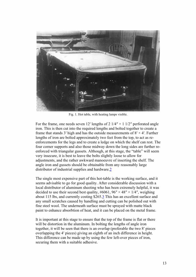
Fig. 1. Hot table, with heating lamps visible.
For the frame, one needs seven 12′ lengths of 2 1/4″ × 1 1/2″ perforated angle iron. This is then cut into the required lengths and bolted together to create a frame that stands 3′ high and has the outside measurements of 8′ × 4′. Further lengths of iron are bolted approximately two feet from the top, to act as re-enforcements for the legs and to create a ledge on which the shelf can rest. The four corner supports and also those midway down the long sides are further re-enforced with triangular gussets. Although, at this stage, the “table” will seem very insecure, it is best to leave the bolts slightly loose to allow for adjustments, and the rather awkward manoeuvre of inserting the shelf. The angle iron and gussets should be obtainable from any reasonably large distributor of industrial supplies and hardware.2
The single most expensive part of this hot-table is the working surface, and it seems advisable to go for good quality. After considerable discussion with a local distributor of aluminum sheeting who has been extremely helpful, it was decided to use their second best quality, #6061, 96″ × 48″ × 1/4″, weighing about 115 lbs, and currently costing $265.3 This has an excellent surface and any small scratches caused by handling and cutting can be polished out with fine steel wool. The underneath surface must be sprayed with matte black paint to enhance absorbtion of heat, and it can be placed on the metal frame.
It is important at this stage to ensure that the top of the frame is flat or there will be distortion in the aluminum. In bolting the lengths of angle iron together, it will be seen that there is an overlap (preferable the two 8′ pieces overlapping the 4′ pieces) giving an eighth of an inch difference in height. This difference can be made up by using the few left-over pieces of iron, securing them with a suitable adhesive.
13

The aluminum sheet is not secured at the edges in any way, to allow for possible expansion, but the manufacturers say this is unlikely to be more than .015″.
The shelf consists of a 4′ × 8′ sheet of five-plywood, A/D quality.4 This is sawn in half to give two pieces of 4′ square, both of which are then painted with two coats of poly-urethane wood sealer, and placed, A side up, on the ledges provided by the angle iron frame. Each half is then marked out into nine squares of 16″ each, in the middle of which is screwed a porcelain lamp socket.
These are then wired together in parallel into four groups using Romex 12/2 (two groups with five lamps, and two with four). This enables one to use only half, or even three-quarters of the table if necessary (Fig. 2). With eighteen heat bulbs of 250 watts each, one is using 4500 watts; so given that the electricity supply is 120 volts, one needs a total of 37.5 amperes. Each group of lamps is plugged into a grounded (three hole) socket which is wired to a circuit breaker, with the thermostat let in between the socket and the breaker (Fig 3).
Fig. 2. Detail of heating lamp arrangement.
14
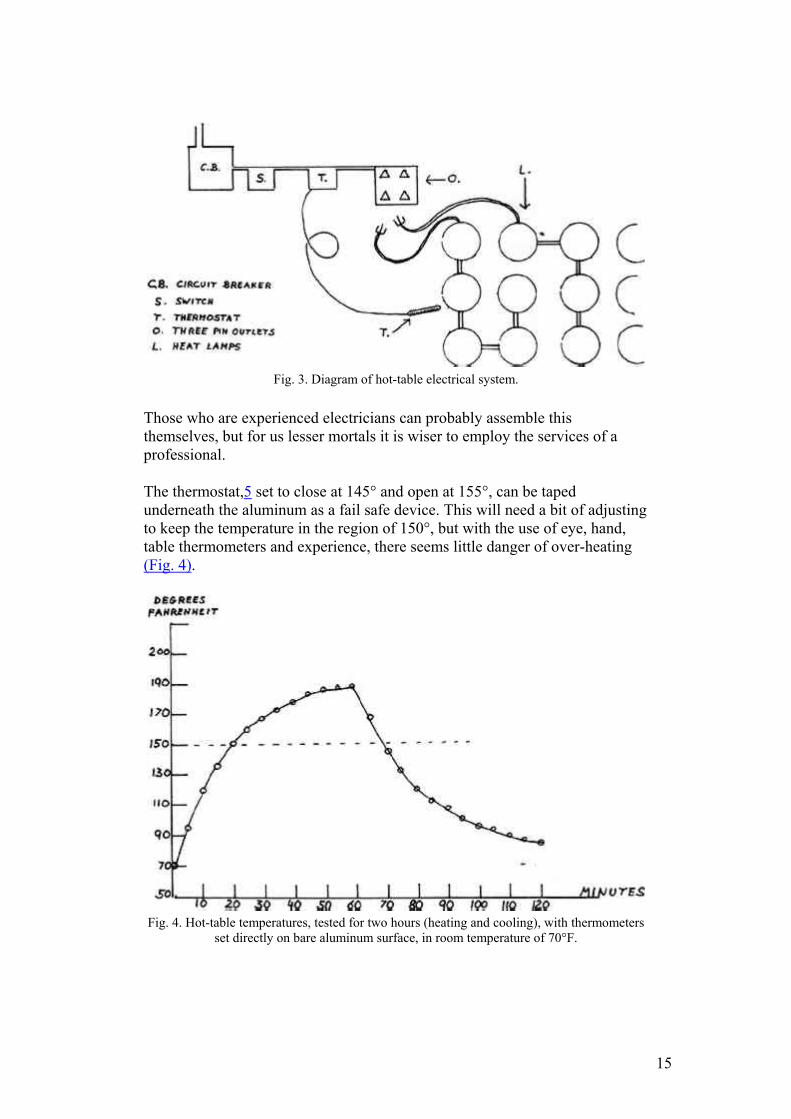
Fig. 3. Diagram of hot-table electrical system.
Those who are experienced electricians can probably assemble this themselves, but for us lesser mortals it is wiser to employ the services of a professional.
The thermostat,5 set to close at 145° and open at 155°, can be taped underneath the aluminum as a fail safe device. This will need a bit of adjusting to keep the temperature in the region of 150°, but with the use of eye, hand, table thermometers and experience, there seems little danger of over-heating (Fig. 4).
Fig. 4. Hot-table temperatures, tested for two hours (heating and cooling), with thermometers
set directly on bare aluminum surface, in room temperature of 70°F.
15
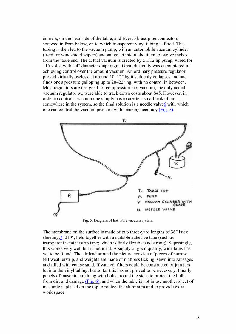
corners, on the near side of the table, and Everco brass pipe connectors screwed in from below, on to which transparent vinyl tubing is fitted. This tubing is then led to the vacuum pump, with an automobile vacuum cylinder (used for windshield wipers) and gauge let into it about ten to twelve inches from the table end. The actual vacuum is created by a 1/12 hp pump, wired for 115 volts, with a 4″ diameter diaphragm. Great difficulty was encountered in achieving control over the amount vacuum. An ordinary pressure regulator proved virtually useless; at around 10–12″ hg it suddenly collapses and one finds one's pressure galloping up to 20–22″ hg, with no control in between. Most regulators are designed for compression, not vacuum; the only actual vacuum regulator we were able to track down costs about $45. However, in order to control a vacuum one simply has to create a small leak of air somewhere in the system, so the final solution is a needle valve6 with which one can control the vacuum pressure with amazing accuracy (Fig. 5).
Fig. 5. Diagram of hot-table vacuum system.
The membrane on the surface is made of two three-yard lengths of 36″ latex sheeting,7 .010″, held together with a suitable adhesive tape (such as transparent weatherstrip tape; which is fairly flexible and strong). Suprisingly, this works very well but is not ideal. A supply of good quality, wide latex has yet to be found. The air lead around the picture consists of pieces of narrow felt weatherstrip, and weights are made of mattress ticking, sewn into sausages and filled with coarse sand. If wanted, filters could be constructed of jam jars let into the vinyl tubing, but so far this has not proved to be necessary. Finally, panels of masonite are hung with bolts around the sides to protect the bulbs from dirt and damage (Fig. 6), and when the table is not in use another sheet of masonite is placed on the top to protect the aluminum and to provide extra work space.
16
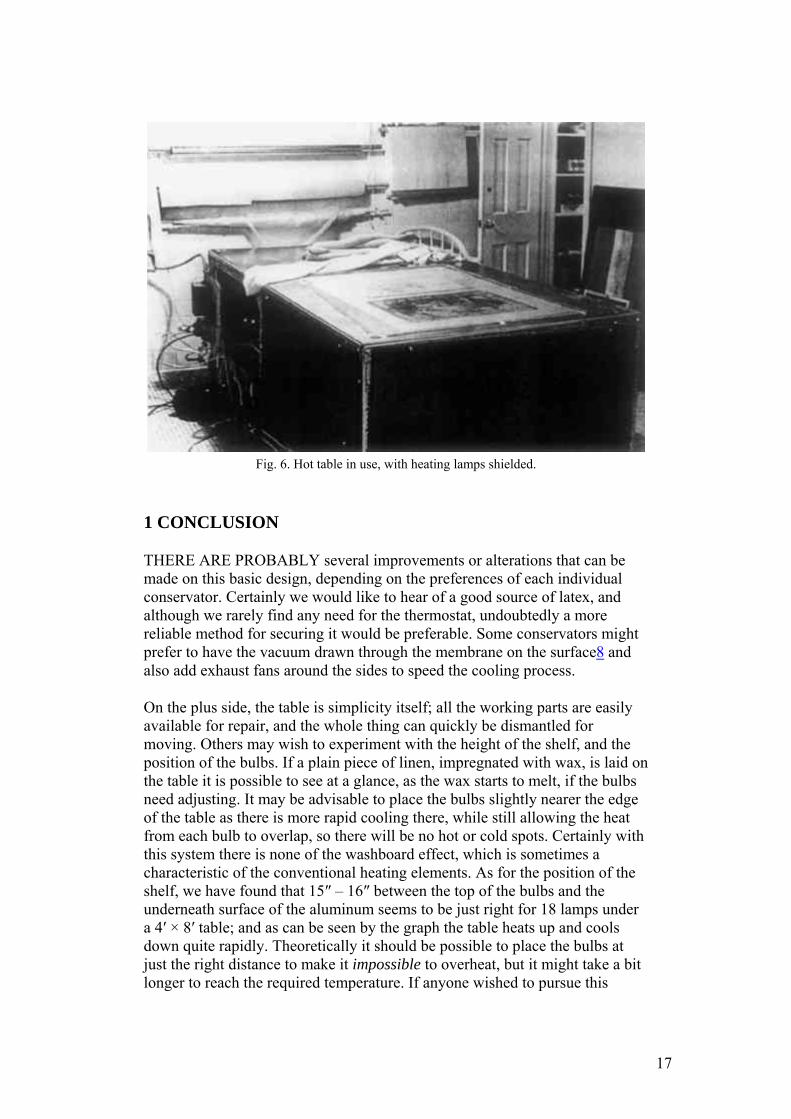
Fig. 6. Hot table in use, with heating lamps shielded.
1 CONCLUSION
THERE ARE PROBABLY several improvements or alterations that can be made on this basic design, depending on the preferences of each individual conservator. Certainly we would like to hear of a good source of latex, and although we rarely find any need for the thermostat, undoubtedly a more reliable method for securing it would be preferable. Some conservators might prefer to have the vacuum drawn through the membrane on the surface8 and also add exhaust fans around the sides to speed the cooling process.
On the plus side, the table is simplicity itself; all the working parts are easily available for repair, and the whole thing can quickly be dismantled for moving. Others may wish to experiment with the height of the shelf, and the position of the bulbs. If a plain piece of linen, impregnated with wax, is laid on the table it is possible to see at a glance, as the wax starts to melt, if the bulbs need adjusting. It may be advisable to place the bulbs slightly nearer the edge of the table as there is more rapid cooling there, while still allowing the heat from each bulb to overlap, so there will be no hot or cold spots. Certainly with this system there is none of the washboard effect, which is sometimes a characteristic of the conventional heating elements. As for the position of the shelf, we have found that 15″ – 16″ between the top of the bulbs and the underneath surface of the aluminum seems to be just right for 18 lamps under a 4′ × 8′ table; and as can be seen by the graph the table heats up and cools down quite rapidly. Theoretically it should be possible to place the bulbs at just the right distance to make it impossible to overheat, but it might take a bit longer to reach the required temperature. If anyone wished to pursue this
17

theory, the exact distance from bulb to aluminum, for even heating could probably be worked out by a heating engineer.
To sum up, we think that this vacuum hot-table, apart from its cheapness, is an attractive proposition because of its safety, relative speed in cooling, and accessibility for repairs.
ACKNOWLEDGEMENTS
GRATEFUL THANKS TO: Robert Williams of Choate Rosemary Hall for his interest and expert advice throughout the whole project. George Buttrick, for his electrical know how. Marsha McCarthy, of Mohawk Aluminum for her interest and advice. Without their help, it is doubtful whether this table would ever have been built.
APPENDIX
1 APPENDIX
REFERENCES
“Heat Seal Lining of a Torn Painting with Beva” by Gustav A.Berger. Studies in Conservation, 20. 1975 pp 136 The angle iron and gussets were obtained from Church and Morse Inc., Meriden, Connecticut, 06450 Aluminum sheeting made by Kaiser Aluminum, Seattle, and distributed by Mohawk Aluminum, Wallingford, Conn., who say they will deliver to any part of the country. A/D plywood has one surface that is good quality (A); the obverse side (D) may contain knots and other blemishes. Pump (Speedaire #2Z627), Thermostat, (hot water control model #2E327) and Vacuum gauge are all made by Dayton Electrical Co., Chicago, and obtainable from any branch of W. W. Graingers. Needle valve and Everco brass fittings are obtainable from wholesale distributors of automobile parts. Diameters are a matter of choice, but 1/4″−3/8″ seems a convenient size. Latex supplied by Greene Rubber of Connecticut, 59 Old Broadway, North Haven, Conn. “Electrost$atic Hold as a Pressure Source in the Lining of Paintings” by Robert E.Fieux. Preprints of Fifth Annual Meeting, Boston. 1977 pp. 41
18
JAIC 1980, Volume 20, Number 1, Article 4 (pp. 36 to 40)
DESIGN AND CONSTRUCTION OF A SUCTION TABLE
Roy L. Perkinson
ABSTRACT—A design for an inexpensive, easily disassembled and cleaned suction table of simple construction is presented, with a description of the materials used. The application of the table in paper conservation treatments is briefly described, and its use for textile conservation is suggested.
SINCE ITS INTRODUCTION by Marilyn Weidner in 19741 the suction table has generated considerable interest among paper conservators. It has become an important tool in solving a variety of problems previously thought difficult or impossible to treat. The table described here was contructed by the paper conservation laboratory at the Museum of Fine Arts in 1976 and has been in regular use since then. The design is only one of many possible variations, but it is hoped that the specific details of construction will be of interest to others who are considering building their own versions.
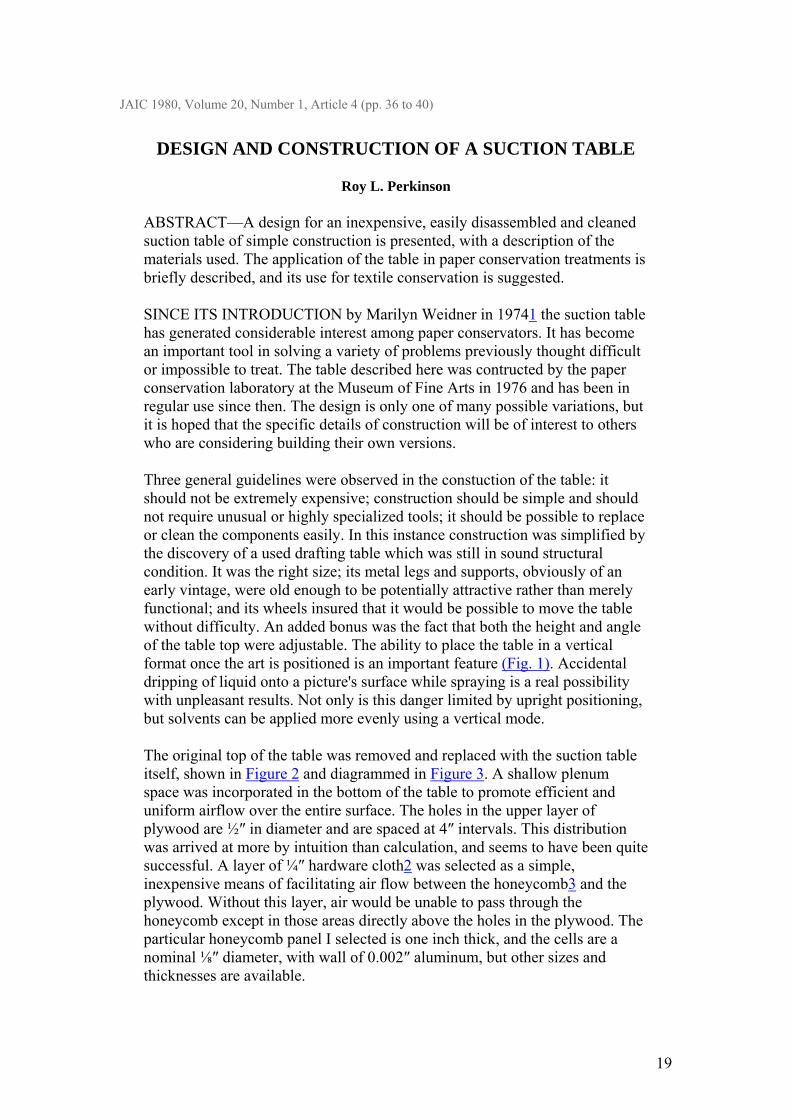
Three general guidelines were observed in the constuction of the table: it should not be extremely expensive; construction should be simple and should not require unusual or highly specialized tools; it should be possible to replace or clean the components easily. In this instance construction was simplified by the discovery of a used drafting table which was still in sound structural condition. It was the right size; its metal legs and supports, obviously of an early vintage, were old enough to be potentially attractive rather than merely functional; and its wheels insured that it would be possible to move the table without difficulty. An added bonus was the fact that both the height and angle of the table top were adjustable. The ability to place the table in a vertical format once the art is positioned is an important feature (Fig. 1). Accidental dripping of liquid onto a picture's surface while spraying is a real possibility with unpleasant results. Not only is this danger limited by upright positioning, but solvents can be applied more evenly using a vertical mode.
The original top of the table was removed and replaced with the suction table itself, shown in Figure 2 and diagrammed in Figure 3. A shallow plenum space was incorporated in the bottom of the table to promote efficient and uniform airflow over the entire surface. The holes in the upper layer of plywood are ½″ in diameter and are spaced at 4″ intervals. This distribution was arrived at more by intuition than calculation, and seems to have been quite successful. A layer of ¼″ hardware cloth2 was selected as a simple, inexpensive means of facilitating air flow between the honeycomb3 and the plywood. Without this layer, air would be unable to pass through the honeycomb except in those areas directly above the holes in the plywood. The particular honeycomb panel I selected is one inch thick, and the cells are a nominal ⅛″ diameter, with wall of 0.002″ aluminum, but other sizes and thicknesses are available.
19
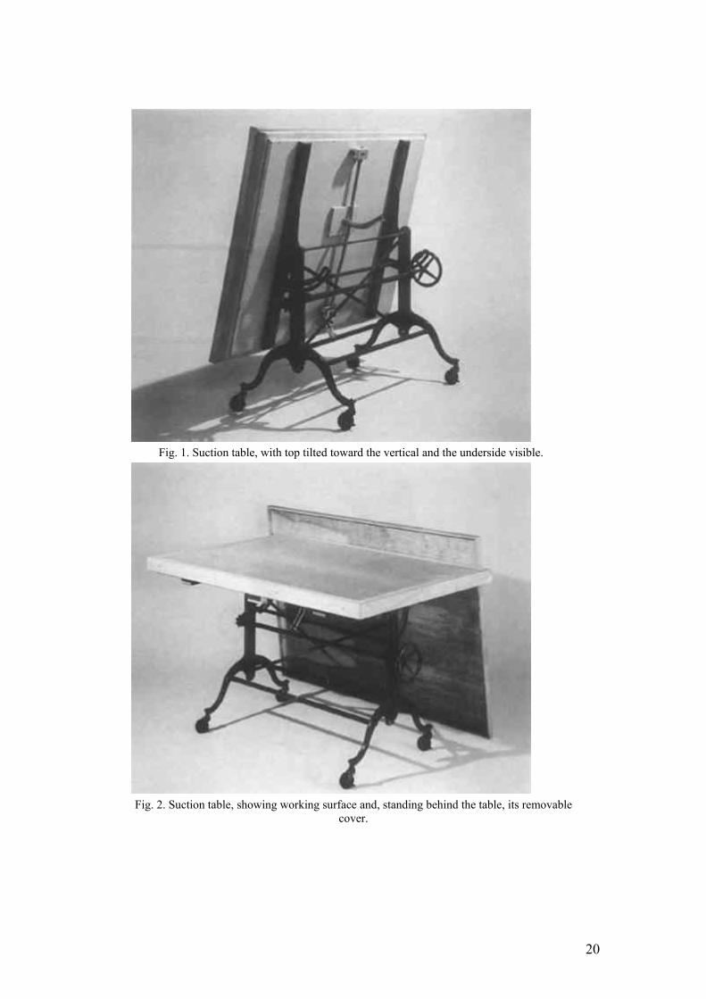
Fig. 1. Suction table, with top tilted toward the vertical and the underside visible.
Fig. 2. Suction table, showing working surface and, standing behind the table, its removable
cover.
20
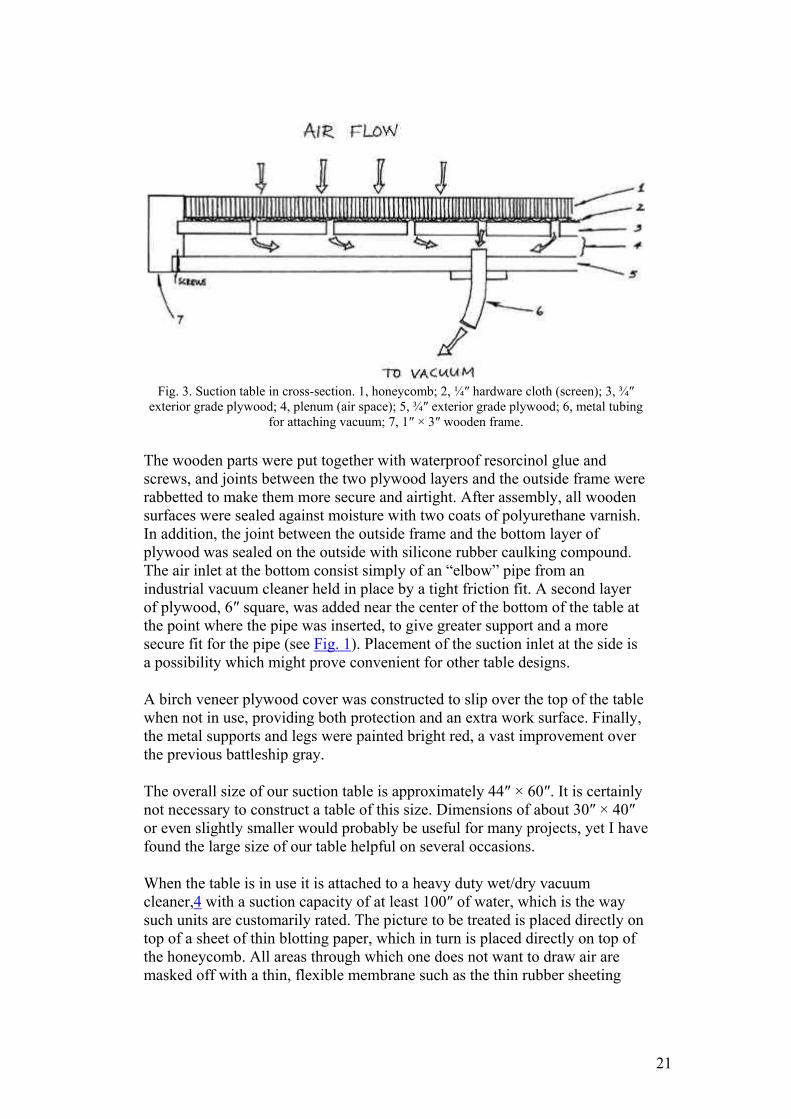
Fig. 3. Suction table in cross-section. 1, honeycomb; 2, ¼″ hardware cloth (screen); 3, ¾″
exterior grade plywood; 4, plenum (air space); 5, ¾″ exterior grade plywood; 6, metal tubing for attaching vacuum; 7, 1″ × 3″ wooden frame.
The wooden parts were put together with waterproof resorcinol glue and screws, and joints between the two plywood layers and the outside frame were rabbetted to make them more secure and airtight. After assembly, all wooden surfaces were sealed against moisture with two coats of polyurethane varnish. In addition, the joint between the outside frame and the bottom layer of plywood was sealed on the outside with silicone rubber caulking compound. The air inlet at the bottom consist simply of an “elbow” pipe from an industrial vacuum cleaner held in place by a tight friction fit. A second layer of plywood, 6″ square, was added near the center of the bottom of the table at the point where the pipe was inserted, to give greater support and a more secure fit for the pipe (see Fig. 1). Placement of the suction inlet at the side is a possibility which might prove convenient for other table designs.
A birch veneer plywood cover was constructed to slip over the top of the table when not in use, providing both protection and an extra work surface. Finally, the metal supports and legs were painted bright red, a vast improvement over the previous battleship gray.
The overall size of our suction table is approximately 44″ × 60″. It is certainly not necessary to construct a table of this size. Dimensions of about 30″ × 40″ or even slightly smaller would probably be useful for many projects, yet I have found the large size of our table helpful on several occasions.
When the table is in use it is attached to a heavy duty wet/dry vacuum cleaner,4 with a suction capacity of at least 100″ of water, which is the way such units are customarily rated. The picture to be treated is placed directly on top of a sheet of thin blotting paper, which in turn is placed directly on top of the honeycomb. All areas through which one does not want to draw air are masked off with a thin, flexible membrane such as the thin rubber sheeting
21

used by dentists (dental dam),5 polyethylene, or mylar. Although I have not encountered this problem, it is conceivable that too much suction coupled with the use of moisture could produce an impression of the honeycomb, evident as a slight irregularity, on the surface of the paper. To guard against this possibility it is advisable to work at the table with excellent light falling at an oblique angle and to be alert at all times for the slightest hint of undesirable changes in the surface texture of the picture. The use of a fine mesh screen such as a polyester silk screen fabric beneath the blotting paper may also assist in maintaining the desired planarity. In an earlier version of the table, a valve was incorporated for the purpose of regulating suction. In practice it was found that regulation could be accomplished effectively and sensitively by simply folding over the desired amount of masking material near the outer edge of the table, allowing air to pass through and thus reducing suction.
To facilitate operation of the table an electrical switch was mounted on each of the two long sides, just beneath the edge of the table. These control a single electrical outlet beneath the table, into which the vacuum cleaner is plugged; therefore the suction can be turned on or off quickly and conveniently, without requiring the conservator to step away from the table.
One of the practical problems associated with the use of the table is that the vacuum cleaner is rather noisy. Although this is not too troublesome for short periods of operation, it may be objectionable if the table is in continuous use for a long time. In addition, if flammable solvents are used on the table, there is the theoretical possibility of ignition. The path of air through the vacuum cleaner is essentially independent of the air passing around the motor, but the design of the motor housing is such that air leaving the holding tank cannot be prevented from coming in contact with the motor. Therefore we explored two alternatives: using a different type of motor in a remote location, or constructing a different housing for the motor. Since the planned renovation of our laboratory will permit the installation of an explosion-proof motor totally outside the work space, we are proceeding with the first alternative, and the table will then be attached to an exhaust tube within the laboratory. The second alternative could be accomplished, I believe, by purchasing a motor of the correct size and type, then constructing a soundproof container for it and attaching an exhaust tube to it which would conduct vapors to a safe distance away, or possibly directly into an existing fume exhaust system. The Lamb Electric two-stage by-pass vacuum motor might be satisfactory for this purpose.6 (I am grateful to Tim Vitale, Intermuseum Laboratory, for this suggestion.)
I would like to make a general observation on the use of the table which may be so obvious that it could be overlooked. The work room in which the table is used should be very clean so that the air drawn into the table will be as free as possible of particulate matter. Air is, after all, being drawn through the picture and paper can act as a filter for air-borne particulate matter. To check the air quality, it would be advisable to run the table for an hour or two using a sheet
22
of blotting paper in place of a picture and leaving only a very small area uncovered by the masking material. If signs of a grayish deposit are produced on the blotting paper, steps should be taken to provide a cleaner environment for the table. One might also consider placing a thin blotter over the picture as an added precaution during drying/conditioning operations, which tend to require more time than other procedures. The top blotter will block particulate material from the surface of the art work.
Since the construction of our suction table, we have found it useful for a variety of problems such as reduction of stains from water or pressure sensitive tapes, conditioning/drying of moist paper to room humidity, and drying pictures that were executed in a medium that might easily offset during ordinary drying between blotters. We have also observed that the table may be helpful in other areas of conservation. Our textile conservator, Leslie Smith, has found it useful for certain procedures such as the removal of deposits of glue from textiles whose colors would otherwise be adversely affected by overall treatment with water.
REFERENCES
AIC Bulletin, vol. 14, no. 2, pp. 115–122. Hardware cloth is a heavy, open-weave wire screen and is available at many hardware stores or lumber supply houses. Honeycomb panels are available from Hexcel Corporation, P.O. Box 709, Bel Aire, Maryland 21014. Pullman model JB-102 industrial vacuum cleaner. Pullman/Holt Products, Division of Purex Corp., 123 Medford Street, Malden, Mass. 02148. Clarke model 612 vacuum cleaner. Clarke-Gravely Corp., 2800 Estes Street, Muskegon, Mich. 49441. For the address of the nearest distributor of flexible rubber sheeting write Hygenic Rubber Products, 1245 Home Avenue, Akron, Ohio 44310. Lamb Electric two-stage by-pass universal vacuum motor with tangential discharge, model no. 115334, available from W.W. Grainger, Inc., stock no. 2M174. Branches of W.W. Grainger are located in many cities.
23
JAIC 1983, Volume 22, Number 2, Article 4 (pp. 82 to 91)
LEAF CASTING ON THE SUCTION TABLE
Robert Futernick
ABSTRACT—Modification of the “leaf casting” technique for use on the vacuum suction table is described. A plastic container, placed above an area of missing paper, holds water and pulp until suction is applied from below. Fibers, pulled evenly into proper position, bond with the edge of the original sheet. Prints or drawings that exceed the size of the suction table may still be treated. Through localized wetting or the use of alcohol as the casting liquid, certain problems associated with water soluble media and standard casting procedure can be overcome.
THE BEST REPAIR of paper with losses or tears requires a technique that is appropriate to the particular qualities of a paper, including consideration of intended use of the item. For example, a hole in a book page could be filled with strong, flexible Japanese paper to accommodate handling. The same hole in a master drawing would have different repair requirements, since minimizing the visual effect of damage would be of greater concern. The availability of a growing number of repair technologies enables the conservator to meet the needs presented by particular problems. Some repair methods are as old as papermaking itself, while other techniques have evolved during the last 30 years. Modification of the “leaf casting” technique for use on the vacuum suction table offers a new refinement for repair and is the subject of this paper.
Historically, filling holes with similar paper has been the most frequently used repair method. It can work well, but success will depend on adequate time to do the task, a good selection of repair papers, a minimum of edge discoloration, and the skill of the conservator. Problems can develop, however. Secure joining of the insert to the original may be difficult, especially with thick, brittle paper. Also, distortion of the original sheet can develop because of the different expansion characteristics of the two papers or the introduction of adhesive necessary for joining the insert.
Because of its strength and flexibility, Japanese paper has been widely used for book leaf repair. Two or more thin sheets laminated together and slightly overlapping the original can create an excellent fill. Though different in color and texture from many Western papers, Japanese paper inserts often provide a sympathetic match. This method seems to have less propensity for paper distortion than other techniques. Furthermore, the strain of attachment is spread over a larger area. This may be extremely important when the edge of the original sheet is weak or the intended use of the material involves extensive handling.
24
1 LEAF CASTING
IN THE LATE 1950s, Esther Alkalay and Ulia Petrovna Nyuksha began experimenting with the concept of filling missing areas in paper with fibers suspended in a liquid medium. By 1961, equipment for this purpose had been developed and was in use in laboratories located in Eastern Europe and the U.S.S.R. The process has come to be known as “leaf casting,” and is best described in the preprints of the 1980 Cambridge Conference (see bibliography). Today the Library of Congress and the Northeast Document Conservation Center both use leaf casting machines based on Alkalay's design. Other models, varying in cost and sophistication, have been developed in recent years and are in use in laboratories throughout the world.
1.1 Steps of traditional leaf casting
1. The damaged paper should be thoroughly wet. (Extending the soak time and increasing the wetness of the sheet aids in later bonding.)
2. The paper is placed on a permeable surface at the bottom of the leaf casting tub. A hold-down mechanism is usually employed to restrict movement of the damaged sheet when water is added to the area above the paper.
3. A precise amount of pulp of appropriate fiber type and color is stirred into the water bath. It is important that measurement of the missing area and paper thickness be accurate and the pulp addition be correct so that the cast fills will equal the thickness of the original paper. Simple graph paper or a planimeter can facilitate this calculation.
4. Suction, whether from an electric pump or gravity, is applied to the space below the damaged work. Water in the top portion drains through the voided spaces only, depositing an even layer of pulp across the loss.
1.2 Characteristics and Qualities of Leaf Casting
Leaf casting has distinct advantages over other methods of filling losses. If one's work is organized and equipment is properly adjusted, damage to paper can be repaired very quickly. It is possible to create a smooth, flexible and unobtrusive transition from the fill to the original paper. And if fibers of similar dimensional characteristics are selected and prepared, distortion can be minimized or avoided. However, there are areas of concern and potential problems in leaf casting, and they should be understood in order to take full advantage of this technique.
The bonding of the fill material to the old paper can be problematic. The quality of connection will depend on a) the state of deterioration of the original sheet; b) the bonding characteristic of the pulp prepared for casting; c) the edge of the loss and the degree of fiber extension; and d) the speed that water drains through the losses.
25
In the past, various kinds of adhesives have been added to the casting liquid to improve bonding. Unfortunately, adhesives affect the entire object during the period of immersion and drainage, not just the fill. This changes the nature of the paper—at the very least—and if the adhesive material proves to have poor aging characteristics, the entire artifact will suffer. Therefore, the addition of adhesives, though helpful in bonding, should be carefully considered and avoided when possible.
Conventional leaf casting requires the complete immersion of the paper in water. Clearly, many items cannot undergo this action without risking loss or alteration of the media. As a remedy, application of fixing agents has been suggested. However, it seems imprudent to impose such an altering measure just for the purpose of repair when other satisfactory methods are available. Hand pulp technique and localized leaf casting methods do not require total water immersion.
During leaf casting, there is some pulp deposition onto the surface of the original paper. As the fluid level in the tank gets low during the final stage of drainage, some of the fibers in the solution will become affixed to the surface of the original. This may be minimized if the pulp-in-fluid concentration is kept low, though in certain cases some cleanup may be necessary. (If the work is one-sided and the casting takes place with the work face down, then slight deposition on the verso may not be an issue.)
In an early publication too obscure to remember, reference is made to the employment of chronic gum chewers for major restoration ventures. Here, beating and fibrilation of fibers with cuspid and molar action is gentle but thorough, with chemical processing provided by enzymatic mechanisms (spit). Unfortunately, with leaf casting activity on the rise, it has become more and more difficult for conservators to locate eager chompers to fill increasing demand.
Many conservators have turned to the use of household blenders for conversion of old paper to pulp. Recently, blender preparation has been criticized in the literature in favor of beating devices especially designed for the purpose. Certainly, beating machines do provide precise control over fiber length and hydration and they will accommodate the use of raw fibers. Petherbridge points out that bonding and dimensional stability is very dependent on pulp quality and preparation. However, the use of expensive equipment is not always practical or necessary. If care is shown in the selection of paper for repulping and the fiber-to-water ratio is properly controlled during beating, the quality of blender-beaten fills may be acceptable for many purposes.
26
2 HAND PULP TECHNIQUE
HAND METHODS for filling losses with paper pulp have been in use around the world for a long time. Keiko Keyes outlined her technique at the AIC Conference in Dearborn in 1976. She demonstrated how a hand method, depending on the skill of the conservator, could be successfully used to repair damaged artwork quickly without requiring expensive equipment. Because the entire sheet does not require complete wetting, artifacts with media too vulnerable for immersion casting can be safely treated with hand technique. Also, more control may be achieved with hand placement of fibers than with mechanical leaf casting. Damaged paper with small-to medium-sized holes are perfect candidates for this method, though larger losses in smooth regular papers are difficult to fill evenly by hand. A combination of hand and mechanical methods for use on a vacuum suction table provides a practical alternative to such problems.
3 VACUUM TABLE
WHEN MARILYN WEIDNER introduced the vacuum suction table at the 1974 AIC meeting, it was difficult to imagine all of its possible applications. Since that time, it has become such an important tool in most laboratories that paper conservators often wonder how they could practice without it. Many people have built, modified, analyzed and used suction tables over the last eight years. Inexpensive home-made models can serve quite well, as can the more expensive and elaborate commercially available models. Important factors to consider for both general use of the vacuum table and leaf casting are:
1. Openness of surface. Thick masonry tops tend to restrict air flow and become clogged.
2. Flatness of surface. Any material other than very fine screen or some perforated metals will impose their texture on the paper or blotter in contact with it.
3. Suction. The pump/fan arrangement should have the capability of lifting a column of water at least 80 inches high.
4. Air flow. This will vary depending on the size of the table. Generally 20 cubic feet per minute (CFM) per square foot of table surface is a reasonable guideline. A table 2′ × 3′ (6 × 20 CFM) would perform quite well for most purposes with a suction system that could deliver 120 CFM.
4 LEAF CASTING ON THE SUCTION TABLE
UNTIL RECENTLY, the suction table has been primarily used for washing, drying, stain removal, and lining operations. With only slight modification, the suction table can also be used for localized leaf casting. While hand pulp
27
method remains the simplest and most direct approach for small holes, leaf casting on the suction table may be specially useful under certain conditions:
1. In the absence of a conventional leaf casting apparatus. 2. When the art object or document is larger than the dimensions of the
leaf casting machine. 3. When the loss is large and requires a particularly even fill. 4. When the texture of the original sheet is an aesthetically important
element and the repair calls for articulation of paper texture.
4.1 Advantages of suction table casting
1. The entire sheet does not always have to be wet before casting. 2. When water-sensitive media are present, another liquid such as alcohol
may be utilized to carry the pulp into place. 3. Pulp deposition on the original paper is avoided, since very little liquid
is used and only a small area of the original is exposed. 4. The quality of the join can be improved in cases where strength is
important by casting half the fill and then turning the sheet over to complete the fill. This creates an actual encasement or overlapping of the edge on both sides. This variation is not only strong but offers the additional advantage of obscuring a dirty edge.
4.2 Modification of Suction Table for Leaf Casting
With only slight modification, many vacuum/suction table designs may be used for leaf casting. A major issue is the ability of the system to handle safely a gallon or more of water at one time. The liquid should be disposed of before it reaches the suction device. This can be accomplished in several ways:
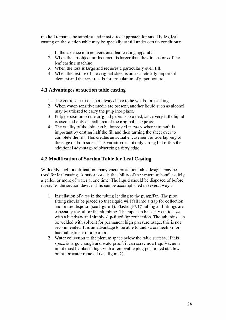
1. Installation of a tee in the tubing leading to the pump/fan. The pipe fitting should be placed so that liquid will fall into a trap for collection and future disposal (see figure 1). Plastic (PVC) tubing and fittings are especially useful for the plumbing. The pipe can be easily cut to size with a handsaw and simply slip-fitted for connection. Though joins can be welded with solvent for permanent high pressure usage, this is not recommended. It is an advantage to be able to undo a connection for later adjustment or alteration.
2. Water collection in the plenum space below the table surface. If this space is large enough and waterproof, it can serve as a trap. Vacuum input must be placed high with a removable plug positioned at a low point for water removal (see figure 2).
28
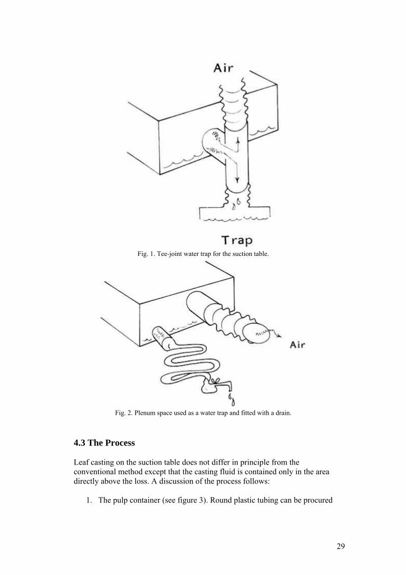
Fig. 1. Tee-joint water trap for the suction table.
Fig. 2. Plenum space used as a water trap and fitted with a drain.
4.3 The Process
Leaf casting on the suction table does not differ in principle from the conventional method except that the casting fluid is contained only in the area directly above the loss. A discussion of the process follows:
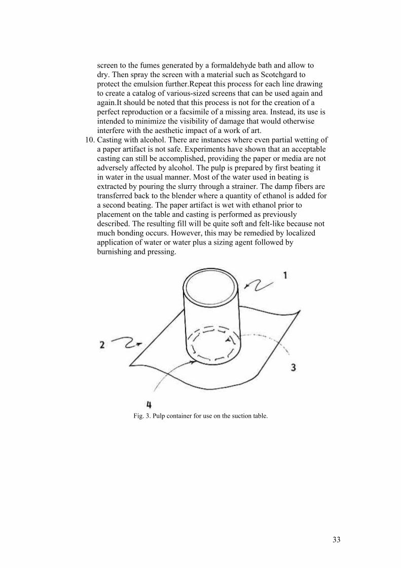
1. The pulp container (see figure 3). Round plastic tubing can be procured
29
in various sizes (2″ to 6″ in diameter) and easily cut into 4″ lengths [1]. (Containers for larger losses are easily fashioned by heating and bending plexiglas sheeting into a rectangular shape, slightly larger than the hole). Thin plastic film (.002″) is cut into a rectangular shape several inches larger than the diameter of the tubing [2]. Then a hole, larger than the loss but slightly smaller than the opening of the container tube, is cut in the center of the rectangle [3]. Silicon adhesive applied to the bottom edge of the tube affixes the container to the plastic mask [4]. This pulp mold will seal itself when suction is applied without harmful downward pressure of the mold on the paper artifact.
2. Arrangement of materials on the suction table (see figure 4). A piece of thin plastic film cut larger than the top of the suction table is placed on the surface so that the extending edges hang over the table [1]. A hole in this film is cut centrally, its dimension slightly larger than the opening of the container mask. Two layers of non-woven spunbonded polyester fabric (Reemay, number 2014 or 2114, from Dupont) are placed over the opening to provide a surface on which to cast [2]. Reemay, an especially suitable material, aids in creating very even pulp formation and imparts a texture much like that achieved by contact with papermaker's felts. The damaged original is set on the Reemay so that the loss is located over the opening in the table [3]. The container can be set directly on the surface of the paper [4]. However, the opening in the mask will not conform exactly to the contour of the loss. If precision in casting is required, pulp deposition in areas other than the hole can be avoided by cutting and properly placing a Reemay mask onto the paper [5]. This extra step can be done quickly and enables one to use just a few different-sized containers for most castings.
3. Delaying drainage. An interval of time is needed for filling the container with water and pulp. A removable plug can be fashioned using plastic film, cut so that it just fits in the container tube (see figure 4 [6]). A string or narrow strip of plastic affixed to one edge of the plug facilitates removal. The plug, inserted inside the container just prior to applying suction, is pulled tightly against the container mask forming a temporary bottom to the container when suction is activated. Lifting the attached string removes the plug, allowing the slurry to be pulled into the area of loss. Larger areas of loss are plugged better if several pieces of plastic film (each with a tail) are placed to overlap each other slightly. Multiple plug removal becomes a louvre action, thus avoiding tidal waves.
4. Selection and processing of pulp. The quality of a casting and its adhesion to the artifact is dependent on many factors: the type of fiber, the nature and duration of processing, and the method of casting and drying. Pulp selection and beating is a complicated issue. The Petherbridge article noted in the bibliography provides a good starting point. However, experimentation and experience is invaluable here. In some cases, it is possible to obtain very satisfactory results by using
30
pulp derived from old, good quality papers beaten in a household blender. The use or addition of linters or commercially processed pulps can provide special advantages in terms of bonding strength and textural quality.
5. Correct addition of pulp to casting liquid. Too much pulp yields a fat, irregular, uneven casting and too little will produce transparency and thinness. (As previously mentioned, it may be desirable in some cases to cast a thin fill from one side, turn the paper over, and complete the casting from the other side. This encases the edge of the original, providing more strength at the join, while perhaps hiding a dirty edge.) The achievement of a fill that has comparable thickness to the original as well as appropriate texture and opacity is a complicated matter, and practicing on holes in mock-ups is necessary to master this technique. However, it is helpful to have a starting point, and the following indicates a method:5,6Cast, press, dry, and cut a rectangle of paper to a convenient size (e.g., 20cm × 25cm). Measure and record the thickness and weight of the sample (e.g., .0125cm thick and 4.0 grams).Determine volume-per-gram by multiplying the length of rectangle times the width times the thickness and divide by the weight of sample (e.g., 20cm × 25cm × .0125cm divided by 4 grams = 1.563 cm3/gram).Find the area of the loss and measure the thickness of the damaged artifact. Counting squares of graph paper or outlining the perimeter of the hole with a planimeter are two methods that have been used to approximate area. Either technique is adequate for occasional casting. However, if the volume of leaf casting activity is high, it may be worth speeding area calculation with the aid of a microcomputer. Simply tracing the outline of the loss with a “light pen” on a Graphics Tablet connected to an Apple Computer, for example, will yield a very quick and accurate area measurement.Determine the weight of pulp required for the casting by dividing the volume of the loss by the volume of a gram of pulp (e.g., area of loss 150cm22 × thickness of artifact .017cm divided by volume/gram 1.563cm33 = 1.63 grams).It is convenient to refrigerate pulp in solutions of known concentration (e.g., 1%) for storage. It is then easy to mix different colored pulps, test the resulting color by drying, and pour out the required amount (e.g., 1.63 grams is approximately equal to 163ml of a 1% solution). The addition of a small quantity of fungicide to the solution will prevent bacterial and mould growth.
6. With suction holding the container and plug in position, the pulp solution is poured into the container. Vacuum pressure is then adjusted. This is a matter of experience, but pressure influences flow and the flow rate will affect the casting. The tail of the plug is quickly pulled. This action opens the bottom of the container, enabling the liquid to drain.
7. The casting is quite wet and much water can be removed by slipping a sheet of blotting paper between the first and second layers of Reemay. Acting as a support, the Reemay can then be lifted to move the paper
31
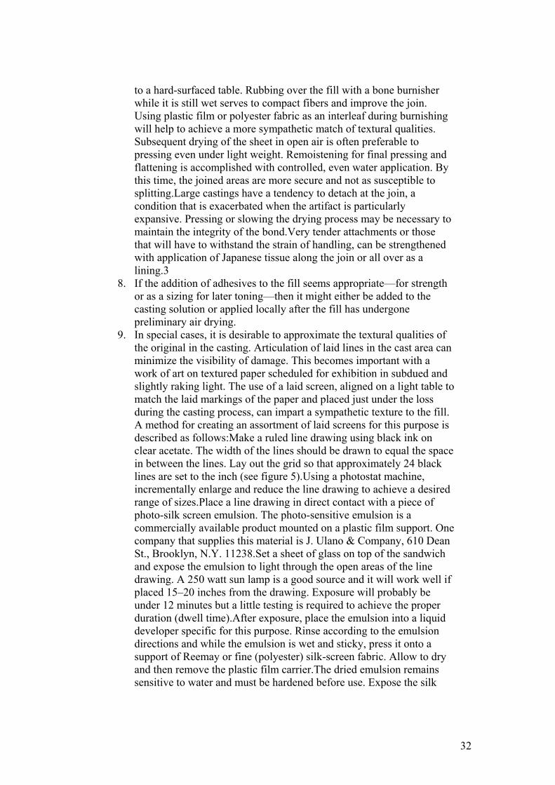
to a hard-surfaced table. Rubbing over the fill with a bone burnisher while it is still wet serves to compact fibers and improve the join. Using plastic film or polyester fabric as an interleaf during burnishing will help to achieve a more sympathetic match of textural qualities. Subsequent drying of the sheet in open air is often preferable to pressing even under light weight. Remoistening for final pressing and flattening is accomplished with controlled, even water application. By this time, the joined areas are more secure and not as susceptible to splitting.Large castings have a tendency to detach at the join, a condition that is exacerbated when the artifact is particularly expansive. Pressing or slowing the drying process may be necessary to maintain the integrity of the bond.Very tender attachments or those that will have to withstand the strain of handling, can be strengthened with application of Japanese tissue along the join or all over as a lining.3
8. If the addition of adhesives to the fill seems appropriate—for strength or as a sizing for later toning—then it might either be added to the casting solution or applied locally after the fill has undergone preliminary air drying.
9. In special cases, it is desirable to approximate the textural qualities of the original in the casting. Articulation of laid lines in the cast area can minimize the visibility of damage. This becomes important with a work of art on textured paper scheduled for exhibition in subdued and slightly raking light. The use of a laid screen, aligned on a light table to match the laid markings of the paper and placed just under the loss during the casting process, can impart a sympathetic texture to the fill. A method for creating an assortment of laid screens for this purpose is described as follows:Make a ruled line drawing using black ink on clear acetate. The width of the lines should be drawn to equal the space in between the lines. Lay out the grid so that approximately 24 black lines are set to the inch (see figure 5).Using a photostat machine, incrementally enlarge and reduce the line drawing to achieve a desired range of sizes.Place a line drawing in direct contact with a piece of photo-silk screen emulsion. The photo-sensitive emulsion is a commercially available product mounted on a plastic film support. One company that supplies this material is J. Ulano & Company, 610 Dean St., Brooklyn, N.Y. 11238.Set a sheet of glass on top of the sandwich and expose the emulsion to light through the open areas of the line drawing. A 250 watt sun lamp is a good source and it will work well if placed 15–20 inches from the drawing. Exposure will probably be under 12 minutes but a little testing is required to achieve the proper duration (dwell time).After exposure, place the emulsion into a liquid developer specific for this purpose. Rinse according to the emulsion directions and while the emulsion is wet and sticky, press it onto a support of Reemay or fine (polyester) silk-screen fabric. Allow to dry and then remove the plastic film carrier.The dried emulsion remains sensitive to water and must be hardened before use. Expose the silk
32
screen to the fumes generated by a formaldehyde bath and allow to dry. Then spray the screen with a material such as Scotchgard to protect the emulsion further.Repeat this process for each line drawing to create a catalog of various-sized screens that can be used again and again.It should be noted that this process is not for the creation of a perfect reproduction or a facsimile of a missing area. Instead, its use is intended to minimize the visibility of damage that would otherwise interfere with the aesthetic impact of a work of art.
10. Casting with alcohol. There are instances where even partial wetting of a paper artifact is not safe. Experiments have shown that an acceptable casting can still be accomplished, providing the paper or media are not adversely affected by alcohol. The pulp is prepared by first beating it in water in the usual manner. Most of the water used in beating is extracted by pouring the slurry through a strainer. The damp fibers are transferred back to the blender where a quantity of ethanol is added for a second beating. The paper artifact is wet with ethanol prior to placement on the table and casting is performed as previously described. The resulting fill will be quite soft and felt-like because not much bonding occurs. However, this may be remedied by localized application of water or water plus a sizing agent followed by burnishing and pressing.
Fig. 3. Pulp container for use on the suction table.
33
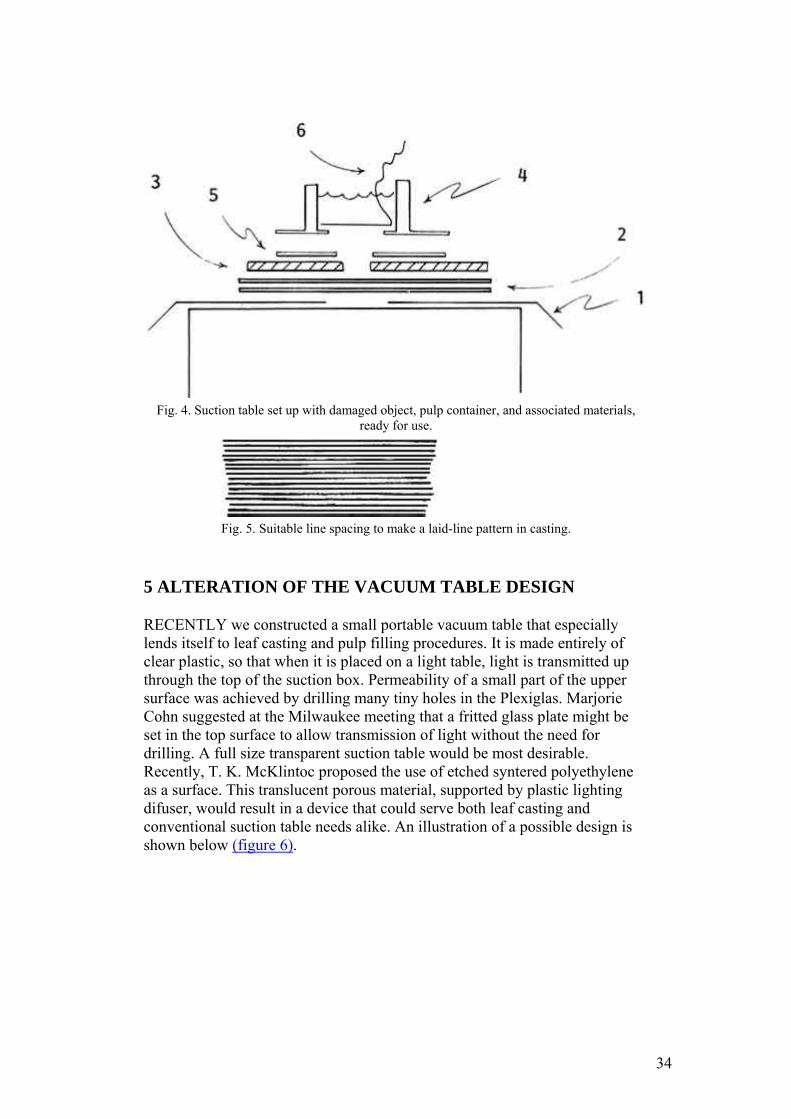
Fig. 4. Suction table set up with damaged object, pulp container, and associated materials,
ready for use.
Fig. 5. Suitable line spacing to make a laid-line pattern in casting.
5 ALTERATION OF THE VACUUM TABLE DESIGN
RECENTLY we constructed a small portable vacuum table that especially lends itself to leaf casting and pulp filling procedures. It is made entirely of clear plastic, so that when it is placed on a light table, light is transmitted up through the top of the suction box. Permeability of a small part of the upper surface was achieved by drilling many tiny holes in the Plexiglas. Marjorie Cohn suggested at the Milwaukee meeting that a fritted glass plate might be set in the top surface to allow transmission of light without the need for drilling. A full size transparent suction table would be most desirable. Recently, T. K. McKlintoc proposed the use of etched syntered polyethylene as a surface. This translucent porous material, supported by plastic lighting difuser, would result in a device that could serve both leaf casting and conventional suction table needs alike. An illustration of a possible design is shown below (figure 6).
34
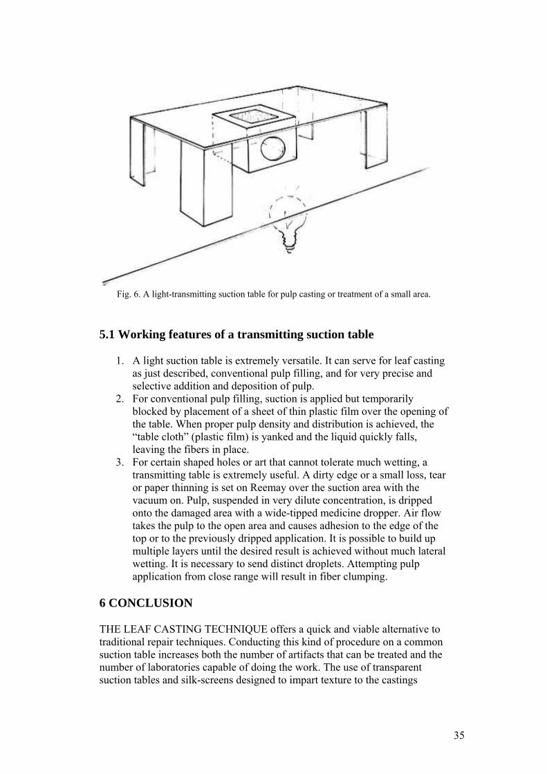
Fig. 6. A light-transmitting suction table for pulp casting or treatment of a small area.
5.1 Working features of a transmitting suction table
1. A light suction table is extremely versatile. It can serve for leaf casting as just described, conventional pulp filling, and for very precise and selective addition and deposition of pulp.
2. For conventional pulp filling, suction is applied but temporarily blocked by placement of a sheet of thin plastic film over the opening of the table. When proper pulp density and distribution is achieved, the “table cloth” (plastic film) is yanked and the liquid quickly falls, leaving the fibers in place.
3. For certain shaped holes or art that cannot tolerate much wetting, a transmitting table is extremely useful. A dirty edge or a small loss, tear or paper thinning is set on Reemay over the suction area with the vacuum on. Pulp, suspended in very dilute concentration, is dripped onto the damaged area with a wide-tipped medicine dropper. Air flow takes the pulp to the open area and causes adhesion to the edge of the top or to the previously dripped application. It is possible to build up multiple layers until the desired result is achieved without much lateral wetting. It is necessary to send distinct droplets. Attempting pulp application from close range will result in fiber clumping.
6 CONCLUSION
THE LEAF CASTING TECHNIQUE offers a quick and viable alternative to traditional repair techniques. Conducting this kind of procedure on a common suction table increases both the number of artifacts that can be treated and the number of laboratories capable of doing the work. The use of transparent suction tables and silk-screens designed to impart texture to the castings
35
provide further refinement now available to the conservator.
ACKNOWLEDGEMENTS
THE SUCCESS of this project was dependent on the help and patience of all the people in our laboratory, namely Pauline Mohr, Patricia Morris, Linda Odgen, Sylvia Rodgers, and Janice Mae Schopfer. Special acknowledgement goes to Keiko Keyes. It was through several meetings with Keiko that the original concept was refined and simplified. Finally, this paper became much more readable after the careful attention of Jennifer Futernick.
REFERENCES
Alkalaj, Stella. “The Chemical Laboratory for Hygiene, Conservation and Restoration of Damaged Written Materials.” Restaurator1:2 (1969), pp.87–91. Wachter, Otto: “Methods of Restoring Old Prints, Documents and Drawings Using Liquid Paper Pulp,” I.I.C. Lisbon Conference 1972, Conservation of Paintings and the Graphics Arts (1972), pp. 971–974. Alkalay, Esther Boyd. “The History and Development of Leaf Casting,” The Conservation of Library and Archive Materials and the Graphics Arts, Cambridge 1980 Preprints (1980), p. 187. Petherbridge, Guy. “Analysis, Specification, and Calculation in the Preparation of Leaf Casting Pulp: A Methodology.” The Conservation of Library and Archive Material and the Graphic Arts, Cambridge 1980 Preprints (1980), pp. 189–209. Keyes, Keiko Mizushima, and Farnsworth, Donald S. “Practical Application of Paper Pulp in the Conservation of Works of Art on Paper.” Preprints. Fourth annual meeting of the American Institute for Conservation (1976), pp. 76–86. Perkinson, Roy, and Futernick, Robert. “Questions Concerning the Design of Paper Pulp for Repairing Art on Paper.” Preservation of Paper and Textiles of Historic and Artistic Value. No. 164, 1977 (JohnWilliam, editor; published by American Chemical Society). Weidner, Marilyn Kemp. “A Vacuum Table of Use in Paper Conservation.” Bulletin of the American Institute for Conservation14:2 (1974). DuMeer, Robert, “Construction of a Leaf Caster for Small Laboratories.” Preprints. Sixth annual meeting of the American Institute for Conservation, 1978.
36
JAIC 1994, Volume 33, Number 1, Article 1 (pp. 1 to 23)
AN EXAMINATION OF THE PATINA AND CORROSION MORPHOLOGY OF SOME ROMAN BRONZES
DAVID A. SCOTT
ABSTRACT—The Roman bronze statues of Togati, Roma, and Venus (Demeter) and in the collection of the J. Paul Getty Museum were subject to a detailed technical study. Of particular interest are their unusual, matte, and finely preserved patinas, which closely parallel another bronze, the Nike, in the Cleveland Museum of Art. The bronzes, which date to A.D. 40–68, are described and analyzed and an account of their corrosion is given, drawing on the early work of W. von Geilmann, who examined the corrosion of bronzes from sandy soils in Germany. The patinas of these objects contain substantial amounts of tin oxide and also display warty corrosion. It was postulated, and confirmed by analysis, that patinas of this kind should contain no chloride ions; thus, there are at least two types of warty corrosion of ancient bronzes. The first type, as here, is chemically stable and does not necessarily require strictly regulated humidity conditions. The second type of warty corrosion is related to the presence of chlorides, usually with an accumulation of cuprous chloride. The three bronzes studied here are closely related and are almost certainly from the same burial deposit, as evidenced by their associated soil and minerals. These materials were not completely cleaned from the surfaces of the bronzes, so essential information regarding their origin was preserved. Cleaning during conservation to a uniform “original surface” or “marker layer” would have removed this important evidence.
1 INTRODUCTION
The aim of this paper is to examine, in detail, the corrosion and patina of some Roman bronzes in the collection of the J. Paul Getty Museum. Strictly speaking, “patina” and “corrosion” are different words for the same surface alteration, but here “patina” will be used to describe a smooth, continuous layer that preserves detail and shape, while “corrosion” is used to describe mineral deposits and surface accretions that do not form a continuous and smooth layer.
Patina formation and the corrosion of ancient bronze objects have been the subject of many previous studies, yet there are few detailed descriptions of the corrosion products of ancient bronzes that comprehensively document identity, mode of appearance, and corrosion micromorphology. Corrosion structures encountered in ancient bronze objects have many similarities to morphological processes that occur during the weathering of soils and rocks, yet the descriptive terms available, taken from metallic corrosion, are not adequate to describe the thick, complex mineral layers that are often observed on ancient bronzes.
The information that can be derived from mineralogical study of ancient bronzes
37
has a direct impact on the degree to which surface cleaning of such objects can be carried out during conservation. One of the most currently favored and best-informed approaches to their surface cleaning is to examine the object carefully under a binocular low-power microscope and clean the artifact to reveal, if possible, an “original surface.” Such surfaces often retain surface detail derived from the object itself, such as spinning marks, inscriptions, and mold lines from casting. It is possible to find this interface preserved in corrosion products because copper alloys frequently exhibit a layered structure in their corrosion, and one of these layers often preserves surface detail, either in the cuprite, malachite, tin oxide, or other “marker layer” or “original surface” (Organ 1963, 1977). Some years ago, Jedrzejewska (1976) drew attention to ancient bronzes as “documents of the past” in their excavated, uncleaned state, and she suggested that those of little or no artistic value should perhaps be preserved, for future scientific study and experiment, in their virginal, uncleaned condition. Another suggestion made by Jedrzejewska (1976) was to leave small strips of corrosion, untouched by cleaning, in less visible places as evidence of the state of the object before conservation.
All of the artifacts examined in this paper could have been cleaned skillfully during conservation to a uniform and aesthetic patina layer. Surface cleaning was carried out, but many areas were left uncleaned, and, as a result, much evidence has been preserved that would otherwise have been lost completely. In some cases—the cleaning of coins and inlaid artifacts, for example—uniform mechanical cleaning to reveal detail is highly desirable, but in other cases, mechanical cleaning can directly remove evidence of archaeological association and of the complete history of the events that have occurred to the object since burial.
The archaeological conservator has a tendency to clean all bronzes mechanically, especially if they have a good patina layer, without appreciating the destruction of evidence that this process necessarily entails. In accord with the advice of Jedrzejewska, echoed recently by Chase (1993) and Bassett and Chase (1993), the Antiquities Conservation Department of the J. Paul Getty Museum has developed a cautious approach to the conservation of archaeological bronzes. As a result, much associated material is now being left uncleaned in areas of less visual importance to an overall appreciation of the object itself.
2 THE OBJECTS AND THEIR CORROSION
2.1 STRUCTURE
The J. Paul Getty Museum houses a small but important collection of classical bronzes, mostly Greek and Roman. Within this collection are three bronzes of Roman origin but otherwise of unknown provenance: Togati, Roma, and Venus (Demeter)(figs. 1–6). These bronzes were reputed to have traveled through the art market from the same source. A fourth bronze, a winged Nike or Victory (Cleveland Museum of Art), was also reputed to have been obtained through the
38
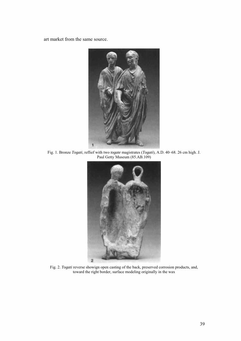
art market from the same source.
Fig. 1. Bronze Togati, reflief with two togate magistrates (Togati), A.D. 40–68. 26 cm high. J.
Paul Getty Museum (85.AB.109)
Fig. 2. Togati reverse showign open casting of the back, preserved corrosion products, and,
toward the right border, surface modeling originally in the wax
39
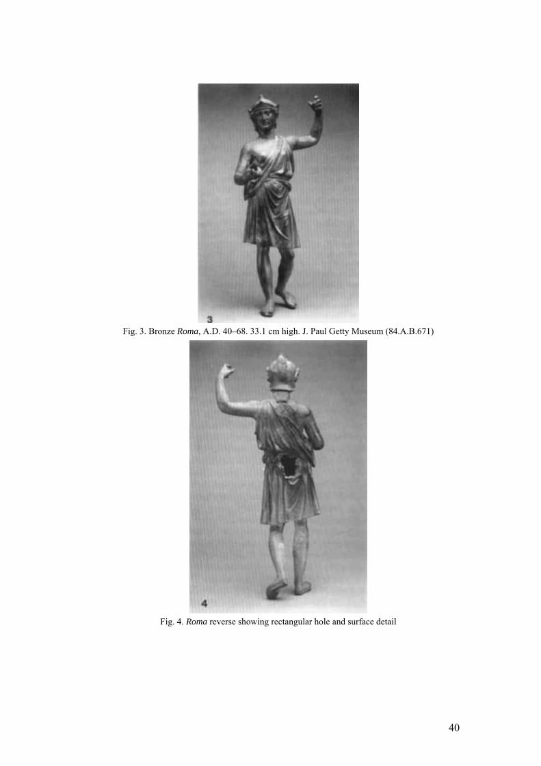
Fig. 3. Bronze Roma, A.D. 40–68. 33.1 cm high. J. Paul Getty Museum (84.A.B.671)
Fig. 4. Roma reverse showing rectangular hole and surface detail
40
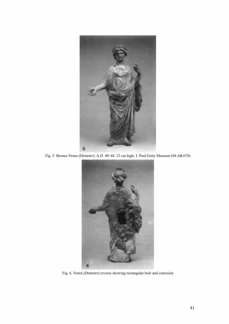
Fig. 5. Bronze Venus (Demeter), A.D. 40–68. 32 cm high. J. Paul Getty Museum (84.AB.670)
Fig. 6. Venus (Demeter) reverse showing rectangular hole and corrosion
41
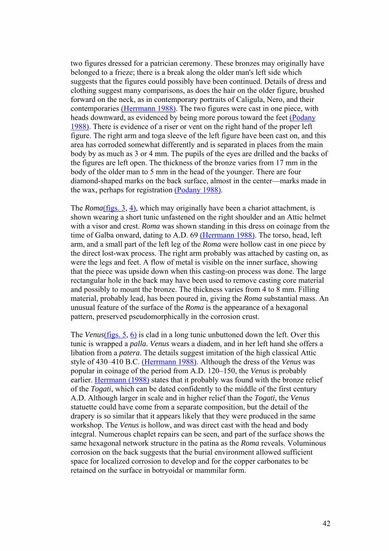
two figures dressed for a patrician ceremony. These bronzes may originally have belonged to a frieze; there is a break along the older man's left side which suggests that the figures could possibly have been continued. Details of dress and clothing suggest many comparisons, as does the hair on the older figure, brushed forward on the neck, as in contemporary portraits of Caligula, Nero, and their contemporaries (Herrmann 1988). The two figures were cast in one piece, with heads downward, as evidenced by being more porous toward the feet (Podany 1988). There is evidence of a riser or vent on the right hand of the proper left figure. The right arm and toga sleeve of the left figure have been cast on, and this area has corroded somewhat differently and is separated in places from the main body by as much as 3 or 4 mm. The pupils of the eyes are drilled and the backs of the figures are left open. The thickness of the bronze varies from 17 mm in the body of the older man to 5 mm in the head of the younger. There are four diamond-shaped marks on the back surface, almost in the center—marks made in the wax, perhaps for registration (Podany 1988).
The Roma(figs. 3, 4), which may originally have been a chariot attachment, is shown wearing a short tunic unfastened on the right shoulder and an Attic helmet with a visor and crest. Roma was shown standing in this dress on coinage from the time of Galba onward, dating to A.D. 69 (Herrmann 1988). The torso, head, left arm, and a small part of the left leg of the Roma were hollow cast in one piece by the direct lost-wax process. The right arm probably was attached by casting on, as were the legs and feet. A flow of metal is visible on the inner surface, showing that the piece was upside down when this casting-on process was done. The large rectangular hole in the back may have been used to remove casting core material and possibly to mount the bronze. The thickness varies from 4 to 8 mm. Filling material, probably lead, has been poured in, giving the Roma substantial mass. An unusual feature of the surface of the Roma is the appearance of a hexagonal pattern, preserved pseudomorphically in the corrosion crust.
The Venus(figs. 5, 6) is clad in a long tunic unbuttoned down the left. Over this tunic is wrapped a palla. Venus wears a diadem, and in her left hand she offers a libation from a patera. The details suggest imitation of the high classical Attic style of 430–410 B.C. (Herrmann 1988). Although the dress of the Venus was popular in coinage of the period from A.D. 120–150, the Venus is probably earlier. Herrmann (1988) states that it probably was found with the bronze relief of the Togati, which can be dated confidently to the middle of the first century A.D. Although larger in scale and in higher relief than the Togati, the Venus statuette could have come from a separate composition, but the detail of the drapery is so similar that it appears likely that they were produced in the same workshop. The Venus is hollow, and was direct cast with the head and body integral. Numerous chaplet repairs can be seen, and part of the surface shows the same hexagonal network structure in the patina as the Roma reveals. Voluminous corrosion on the back suggests that the burial environment allowed sufficient space for localized corrosion to develop and for the copper carbonates to be retained on the surface in botryoidal or mammilar form.
42
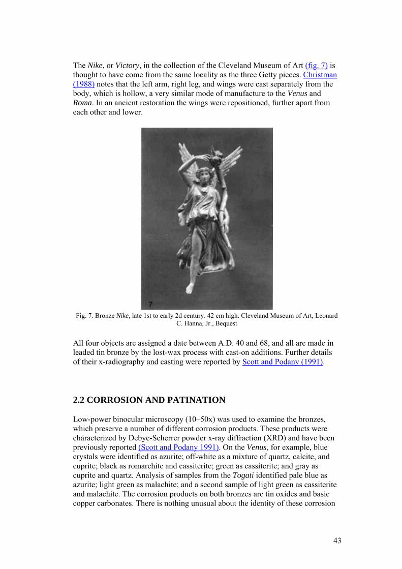
The Nike, or Victory, in the collection of the Cleveland Museum of Art (fig. 7) is thought to have come from the same locality as the three Getty pieces. Christman (1988) notes that the left arm, right leg, and wings were cast separately from the body, which is hollow, a very similar mode of manufacture to the Venus and Roma. In an ancient restoration the wings were repositioned, further apart from each other and lower.
Fig. 7. Bronze Nike, late 1st to early 2d century. 42 cm high. Cleveland Museum of Art, Leonard
C. Hanna, Jr., Bequest
All four objects are assigned a date between A.D. 40 and 68, and all are made in leaded tin bronze by the lost-wax process with cast-on additions. Further details of their x-radiography and casting were reported by Scott and Podany (1991).
2.2 CORROSION AND PATINATION
Low-power binocular microscopy (10–50x) was used to examine the bronzes, which preserve a number of different corrosion products. These products were characterized by Debye-Scherrer powder x-ray diffraction (XRD) and have been previously reported (Scott and Podany 1991). On the Venus, for example, blue crystals were identified as azurite; off-white as a mixture of quartz, calcite, and cuprite; black as romarchite and cassiterite; green as cassiterite; and gray as cuprite and quartz. Analysis of samples from the Togati identified pale blue as azurite; light green as malachite; and a second sample of light green as cassiterite and malachite. The corrosion products on both bronzes are tin oxides and basic copper carbonates. There is nothing unusual about the identity of these corrosion
43
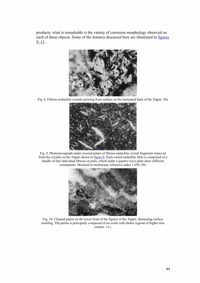
products: what is remarkable is the variety of corrosion morphology observed on each of these objects. Some of the features discussed here are illustrated in figures 8–13.
Fig. 8. Fibrous malachite crystals growing from surface on the uncleaned back of the Togati. 30x
Fig. 9. Photomicrograph under crossed polars of fibrous malachite crystal fragments removed
from the crystals on the Togati shown in figure 8. Each curled malachite fiber is comprised of a bundle of fine individual fibrous crystals, which under a quarter-wave plate show different
orientations. Mounted in meltmount, refractive index 1.659. 45x
Fig. 10. Cleaned patina on the lower front of the figures of the Togati, illustrating surface
mottling. The patina is principally composed of tin oxide with darker regions of higher iron content. 11x.
44
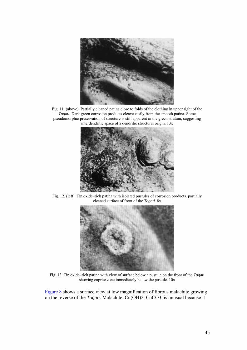
Fig. 11. (above). Partially cleaned patina close to folds of the clothing in upper right of the
Togati. Dark green corrosion products cleave easily from the smooth patina. Some pseudomorphic preservation of structure is still apparent in the green stratum, suggesting
interdendritic space of a dendritic structural origin. 13x
Fig. 12. (left). Tin oxide–rich patina with isolated pustules of corrosion products. partially
cleaned surface of front of the Togati. 8x
Fig. 13. Tin oxide–rich patina with view of surface below a pustule on the front of the Togati
showing cuprite zone immediately below the pustule. 10x
Figure 8 shows a surface view at low magnification of fibrous malachite growing on the reverse of the Togati. Malachite, Cu(OH)2. CuCO3, is unusual because it
45
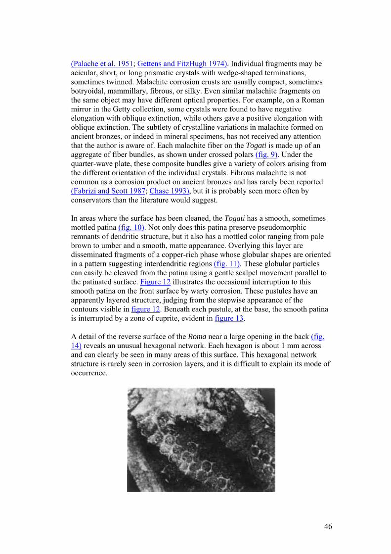
(Palache et al. 1951; Gettens and FitzHugh 1974). Individual fragments may be acicular, short, or long prismatic crystals with wedge-shaped terminations, sometimes twinned. Malachite corrosion crusts are usually compact, sometimes botryoidal, mammillary, fibrous, or silky. Even similar malachite fragments on the same object may have different optical properties. For example, on a Roman mirror in the Getty collection, some crystals were found to have negative elongation with oblique extinction, while others gave a positive elongation with oblique extinction. The subtlety of crystalline variations in malachite formed on ancient bronzes, or indeed in mineral specimens, has not received any attention that the author is aware of. Each malachite fiber on the Togati is made up of an aggregate of fiber bundles, as shown under crossed polars (fig. 9). Under the quarter-wave plate, these composite bundles give a variety of colors arising from the different orientation of the individual crystals. Fibrous malachite is not common as a corrosion product on ancient bronzes and has rarely been reported (Fabrizi and Scott 1987; Chase 1993), but it is probably seen more often by conservators than the literature would suggest.
In areas where the surface has been cleaned, the Togati has a smooth, sometimes mottled patina (fig. 10). Not only does this patina preserve pseudomorphic remnants of dendritic structure, but it also has a mottled color ranging from pale brown to umber and a smooth, matte appearance. Overlying this layer are disseminated fragments of a copper-rich phase whose globular shapes are oriented in a pattern suggesting interdendritic regions (fig. 11). These globular particles can easily be cleaved from the patina using a gentle scalpel movement parallel to the patinated surface. Figure 12 illustrates the occasional interruption to this smooth patina on the front surface by warty corrosion. These pustules have an apparently layered structure, judging from the stepwise appearance of the contours visible in figure 12. Beneath each pustule, at the base, the smooth patina is interrupted by a zone of cuprite, evident in figure 13.
A detail of the reverse surface of the Roma near a large opening in the back (fig. 14) reveals an unusual hexagonal network. Each hexagon is about 1 mm across and can clearly be seen in many areas of this surface. This hexagonal network structure is rarely seen in corrosion layers, and it is difficult to explain its mode of occurrence.
46
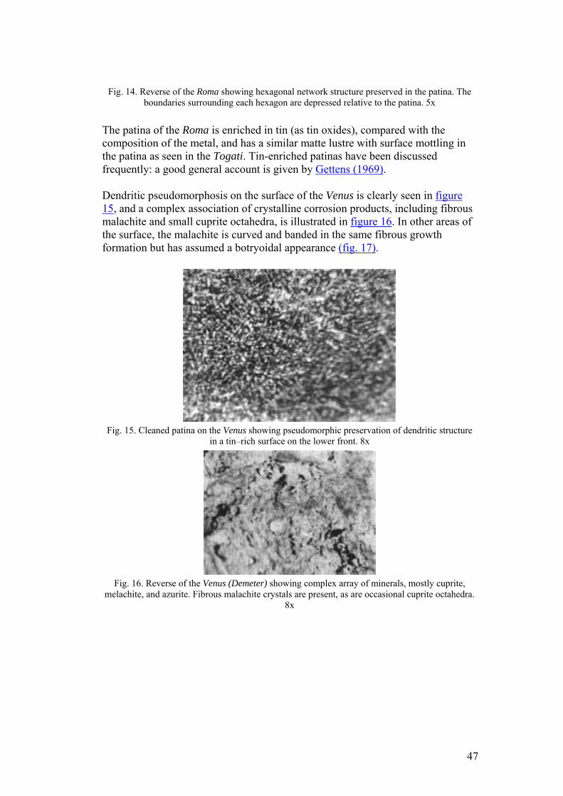
Fig. 14. Reverse of the Roma showing hexagonal network structure preserved in the patina. The boundaries surrounding each hexagon are depressed relative to the patina. 5x
The patina of the Roma is enriched in tin (as tin oxides), compared with the composition of the metal, and has a similar matte lustre with surface mottling in the patina as seen in the Togati. Tin-enriched patinas have been discussed frequently: a good general account is given by Gettens (1969).
Dendritic pseudomorphosis on the surface of the Venus is clearly seen in figure 15, and a complex association of crystalline corrosion products, including fibrous malachite and small cuprite octahedra, is illustrated in figure 16. In other areas of the surface, the malachite is curved and banded in the same fibrous growth formation but has assumed a botryoidal appearance (fig. 17).
Fig. 15. Cleaned patina on the Venus showing pseudomorphic preservation of dendritic structure
in a tin–rich surface on the lower front. 8x
Fig. 16. Reverse of the Venus (Demeter) showing complex array of minerals, mostly cuprite,
melachite, and azurite. Fibrous malachite crystals are present, as are occasional cuprite octahedra. 8x
47
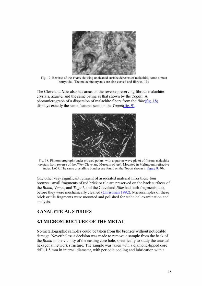
Fig. 17. Reverse of the Venus showing uncleaned surface deposits of malachite, some almost
botryoidal. The malachite crystals are also curved and fibrous. 11x
The Cleveland Nike also has areas on the reverse preserving fibrous malachite crystals, azurite, and the same patina as that shown by the Togati. A photomicrograph of a dispersion of malachite fibers from the Nike(fig. 18) displays exactly the same features seen on the Togati(fig. 9).
Fig. 18. Photomicrograph (under crossed polars, with a quarter-wave plate) of fibrous malachite crystals from reverse of the Nike (Cleveland Museum of Art). Mounted in Meltmount, refractive
index 1.659. The same crystalline bundles are found on the Togati shown in figure 9. 40x
One other very significant remnant of associated material links these four bronzes: small fragments of red brick or tile are preserved on the back surfaces of the Roma, Venus, and Togati, and the Cleveland Nike had such fragments, too, before they were mechanically cleaned (Christman 1992). Microsamples of these brick or tile fragments were mounted and polished for technical examination and analysis.
3 ANALYTICAL STUDIES
3.1 MICROSTRUCTURE OF THE METAL
No metallographic samples could be taken from the bronzes without noticeable damage. Nevertheless a decision was made to remove a sample from the back of the Roma in the vicinity of the casting core hole, specifically to study the unusual hexagonal network structure. The sample was taken with a diamond-tipped core drill, 1.5 mm in internal diameter, with periodic cooling and lubrication with a
48
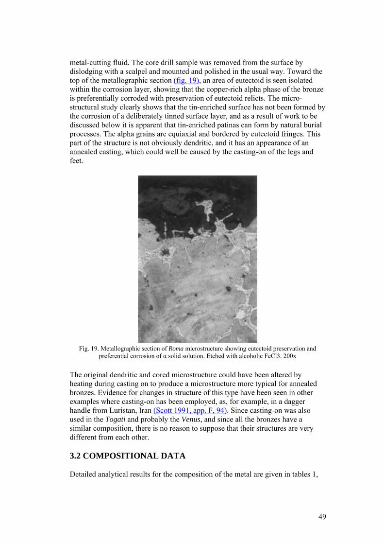
metal-cutting fluid. The core drill sample was removed from the surface by dislodging with a scalpel and mounted and polished in the usual way. Toward the top of the metallographic section (fig. 19), an area of eutectoid is seen isolated within the corrosion layer, showing that the copper-rich alpha phase of the bronze is preferentially corroded with preservation of eutectoid relicts. The micro-structural study clearly shows that the tin-enriched surface has not been formed by the corrosion of a deliberately tinned surface layer, and as a result of work to be discussed below it is apparent that tin-enriched patinas can form by natural burial processes. The alpha grains are equiaxial and bordered by eutectoid fringes. This part of the structure is not obviously dendritic, and it has an appearance of an annealed casting, which could well be caused by the casting-on of the legs and feet.
Fig. 19. Metallographic section of Roma microstructure showing eutectoid preservation and
preferential corrosion of α solid solution. Etched with alcoholic FeCl3. 200x
The original dendritic and cored microstructure could have been altered by heating during casting on to produce a microstructure more typical for annealed bronzes. Evidence for changes in structure of this type have been seen in other examples where casting-on has been employed, as, for example, in a dagger handle from Luristan, Iran (Scott 1991, app. F, 94). Since casting-on was also used in the Togati and probably the Venus, and since all the bronzes have a similar composition, there is no reason to suppose that their structures are very different from each other.
3.2 COMPOSITIONAL DATA
Detailed analytical results for the composition of the metal are given in tables 1,
49
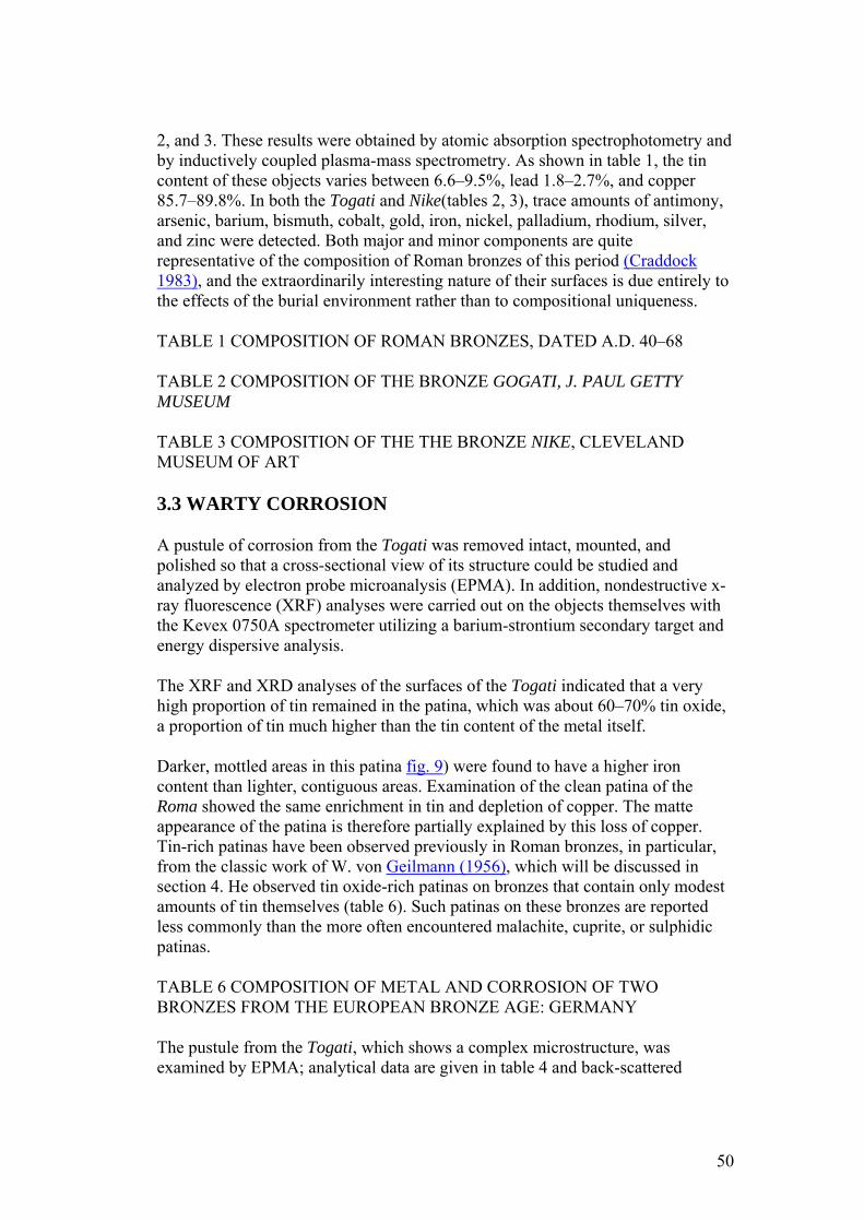
2, and 3. These results were obtained by atomic absorption spectrophotometry and by inductively coupled plasma-mass spectrometry. As shown in table 1, the tin content of these objects varies between 6.6–9.5%, lead 1.8–2.7%, and copper 85.7–89.8%. In both the Togati and Nike(tables 2, 3), trace amounts of antimony, arsenic, barium, bismuth, cobalt, gold, iron, nickel, palladium, rhodium, silver, and zinc were detected. Both major and minor components are quite representative of the composition of Roman bronzes of this period (Craddock 1983), and the extraordinarily interesting nature of their surfaces is due entirely to the effects of the burial environment rather than to compositional uniqueness.
TABLE 1 COMPOSITION OF ROMAN BRONZES, DATED A.D. 40–68
TABLE 2 COMPOSITION OF THE BRONZE GOGATI, J. PAUL GETTY MUSEUM
TABLE 3 COMPOSITION OF THE THE BRONZE NIKE, CLEVELAND MUSEUM OF ART
3.3 WARTY CORROSION
A pustule of corrosion from the Togati was removed intact, mounted, and polished so that a cross-sectional view of its structure could be studied and analyzed by electron probe microanalysis (EPMA). In addition, nondestructive x-ray fluorescence (XRF) analyses were carried out on the objects themselves with the Kevex 0750A spectrometer utilizing a barium-strontium secondary target and energy dispersive analysis.
The XRF and XRD analyses of the surfaces of the Togati indicated that a very high proportion of tin remained in the patina, which was about 60–70% tin oxide, a proportion of tin much higher than the tin content of the metal itself.
Darker, mottled areas in this patina fig. 9) were found to have a higher iron content than lighter, contiguous areas. Examination of the clean patina of the Roma showed the same enrichment in tin and depletion of copper. The matte appearance of the patina is therefore partially explained by this loss of copper. Tin-rich patinas have been observed previously in Roman bronzes, in particular, from the classic work of W. von Geilmann (1956), which will be discussed in section 4. He observed tin oxide-rich patinas on bronzes that contain only modest amounts of tin themselves (table 6). Such patinas on these bronzes are reported less commonly than the more often encountered malachite, cuprite, or sulphidic patinas.
TABLE 6 COMPOSITION OF METAL AND CORROSION OF TWO BRONZES FROM THE EUROPEAN BRONZE AGE: GERMANY
The pustule from the Togati, which shows a complex microstructure, was examined by EPMA; analytical data are given in table 4 and back-scattered
50
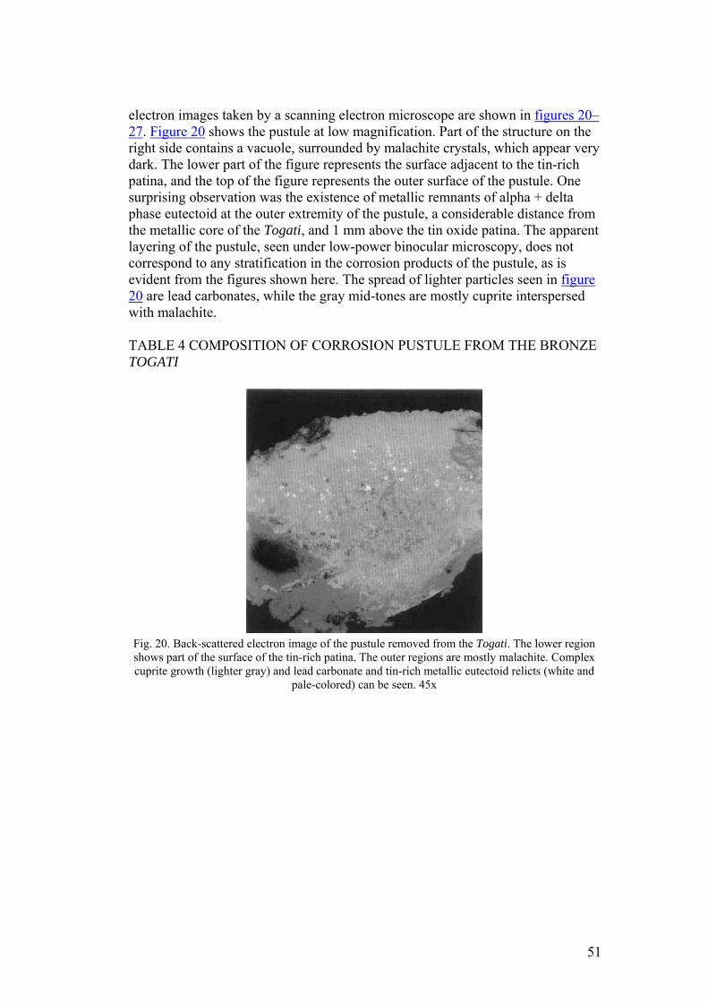
electron images taken by a scanning electron microscope are shown in figures 20–27. Figure 20 shows the pustule at low magnification. Part of the structure on the right side contains a vacuole, surrounded by malachite crystals, which appear very dark. The lower part of the figure represents the surface adjacent to the tin-rich patina, and the top of the figure represents the outer surface of the pustule. One surprising observation was the existence of metallic remnants of alpha + delta phase eutectoid at the outer extremity of the pustule, a considerable distance from the metallic core of the Togati, and 1 mm above the tin oxide patina. The apparent layering of the pustule, seen under low-power binocular microscopy, does not correspond to any stratification in the corrosion products of the pustule, as is evident from the figures shown here. The spread of lighter particles seen in figure 20 are lead carbonates, while the gray mid-tones are mostly cuprite interspersed with malachite.
TABLE 4 COMPOSITION OF CORROSION PUSTULE FROM THE BRONZE TOGATI
Fig. 20. Back-scattered electron image of the pustule removed from the Togati. The lower region shows part of the surface of the tin-rich patina. The outer regions are mostly malachite. Complex cuprite growth (lighter gray) and lead carbonate and tin-rich metallic eutectoid relicts (white and
pale-colored) can be seen. 45x
51
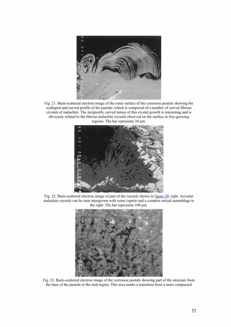
Fig. 21. Back-scattered electron image of the outer surface of the corrosion pustule showing the scalloped and curved profile of the pustule, which is composed of a number of curved fibrous crystals of malachite. The incipiently curved nature of this crystal growth is interesting and is
obviously related to the fibrous malachite crystals observed on the surface in free-growing regions. The bar represents 10 μm.
Fig. 22. Back-scattered electron image of part of the vacuole shown in figure 20, right. Acicular malachite crystals can be seen intergrown with some cuprite and a complex mixed assemblage to
the right. The bar represents 100 μm.
Fig. 23. Back-scattered electron image of the corrosion pustule showing part of the structure from
the base of the pustule to the mid-region. This area marks a transition from a more compacted
52
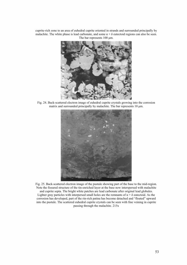
cuprite-rich zone to an area of euhedral cuprite oriented in strands and surrounded principally by malachite. The white phase is lead carbonate, and some α + δ eutectoid regions can also be seen.
The bar represents 100 μm.
Fig. 24. Back-scattered electron image of euhedral cuprite crystals growing into the corrosion
matrix and surrounded principally by malachite. The bar represents 10 μm.
Fig. 25. Back-scattered electron image of the pustule showing part of the base to the mid-region. Note the fissured structure of the tin-enriched layer at the base now interspersed with malachite
and cuprite septa. The bright white patches are lead carbonate after original lead globules. Lighter gray particles with interpersed small holes are the remnants of α + δ eutectoid. As the
corrosion has developed, part of the rin-rich patina has become detached and “floated” upward into the pustule. The scattered euhedral cuprite crystals can be seen with fine veining in cuprite
passing through the malachite. 215x
53
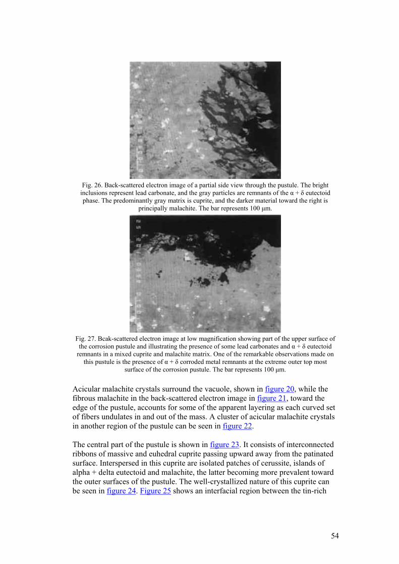
Fig. 26. Back-scattered electron image of a partial side view through the pustule. The bright
inclusions represent lead carbonate, and the gray particles are remnants of the α + δ eutectoid phase. The predominantly gray matrix is cuprite, and the darker material toward the right is
principally malachite. The bar represents 100 μm.
Fig. 27. Bcak-scattered electron image at low magnification showing part of the upper surface of
the corrosion pustule and illustrating the presence of some lead carbonates and α + δ eutectoid remnants in a mixed cuprite and malachite matrix. One of the remarkable observations made on
this pustule is the presence of α + δ corroded metal remnants at the extreme outer top most surface of the corrosion pustule. The bar represents 100 μm.
Acicular malachite crystals surround the vacuole, shown in figure 20, while the fibrous malachite in the back-scattered electron image in figure 21, toward the edge of the pustule, accounts for some of the apparent layering as each curved set of fibers undulates in and out of the mass. A cluster of acicular malachite crystals in another region of the pustule can be seen in figure 22.
The central part of the pustule is shown in figure 23. It consists of interconnected ribbons of massive and euhedral cuprite passing upward away from the patinated surface. Interspersed in this cuprite are isolated patches of cerussite, islands of alpha + delta eutectoid and malachite, the latter becoming more prevalent toward the outer surfaces of the pustule. The well-crystallized nature of this cuprite can be seen in figure 24. Figure 25 shows an interfacial region between the tin-rich
54
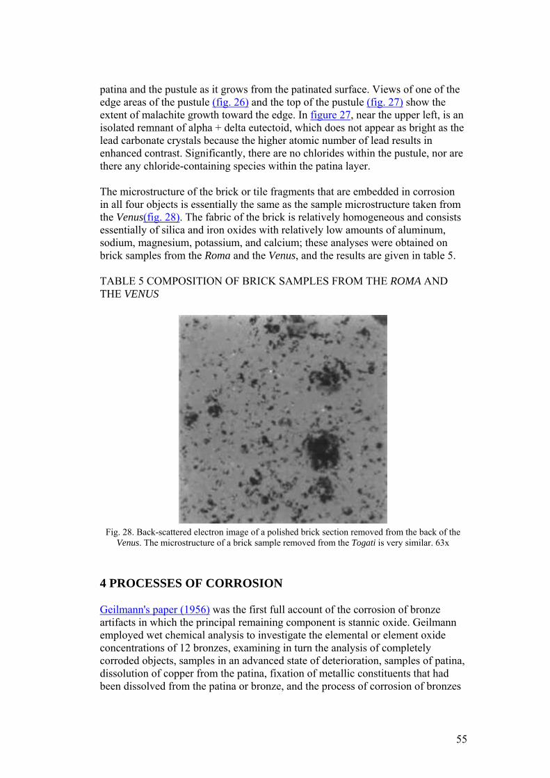
patina and the pustule as it grows from the patinated surface. Views of one of the edge areas of the pustule (fig. 26) and the top of the pustule (fig. 27) show the extent of malachite growth toward the edge. In figure 27, near the upper left, is an isolated remnant of alpha + delta eutectoid, which does not appear as bright as the lead carbonate crystals because the higher atomic number of lead results in enhanced contrast. Significantly, there are no chlorides within the pustule, nor are there any chloride-containing species within the patina layer.
The microstructure of the brick or tile fragments that are embedded in corrosion in all four objects is essentially the same as the sample microstructure taken from the Venus(fig. 28). The fabric of the brick is relatively homogeneous and consists essentially of silica and iron oxides with relatively low amounts of aluminum, sodium, magnesium, potassium, and calcium; these analyses were obtained on brick samples from the Roma and the Venus, and the results are given in table 5.
TABLE 5 COMPOSITION OF BRICK SAMPLES FROM THE ROMA AND THE VENUS
Fig. 28. Back-scattered electron image of a polished brick section removed from the back of the
Venus. The microstructure of a brick sample removed from the Togati is very similar. 63x
4 PROCESSES OF CORROSION
Geilmann's paper (1956) was the first full account of the corrosion of bronze artifacts in which the principal remaining component is stannic oxide. Geilmann employed wet chemical analysis to investigate the elemental or element oxide concentrations of 12 bronzes, examining in turn the analysis of completely corroded objects, samples in an advanced state of deterioration, samples of patina, dissolution of copper from the patina, fixation of metallic constituents that had been dissolved from the patina or bronze, and the process of corrosion of bronzes
55
in the absence of chloride ions. In his examination of objects in an advanced state of corrosion, Geilmann analyzed an urn from a grave site dating to the second or third century A.D. and a sword blade of the Middle Bronze Age dating to about 1000 B.C. from Germany. The sword blade retained a marker layer, or original surface, even when only hydrated tin oxide remained. The urn, on the other hand, had a thin, dark green patina and an almost white tin oxide layer underneath this green surface, which retained the shape of the object. A representative set of these analyses is given in table 6. Geilmann deduced that the absolute tin content of these bronzes was unchanged during corrosion and that no arsenic or antimony were lost either. As a result of interactions with soil minerals, iron and aluminum levels were increased in the patina layer. Geilmann's data, while showing that some objects retain a copper-rich patina, also revealed that others have copper leached from the surface zone until only hydrated tin oxide remains; this hydrated tin oxide layer is then stable to further attack by soil groundwaters. Geilmann states:
The formation of these patinas in burial is ascribed to oxygen and carbon dioxide carried by groundwaters. The salts present in soil solutions can influence the formation of the patina and the nature of the corrosion, but on the whole are of minor importance. The dissolution of copper and other divalent ions is solely due to the free carbon dioxide in the water and the progress of this dissolution is dependent on the concentration of carbon dioxide in solution. If this concentration is high, as for example in humus or porous sandy soils, then the patina is formed rapidly and the continuing dissolution of copper results in an end product of pure tin oxide, whereas in other soils, such as clay, bronzes of the same age may only be covered in a thin patina. In humus-rich sandy soils with a low lime content, there is no inhibiting effect on the decomposition of the patina to create a tin oxide surface, while in lime containing soils, where the soil solutions may contain calcium bicarbonate, this decomposition is inhibited.
Experimental dissolution studies by Geilmann showed that copper would be lost from a synthetic laboratory mixture of copper carbonate and tin oxide. In addition, salts of trivalent iron and aluminum may also contribute to tin oxide enrichment if they are present in the burial environment, and the copper carbonates are preferentially dissolved while iron or aluminum hydroxide is precipitated, accounting for the increase in these metallic ions in the patina. Analyses of soil samples taken from the earth surrounding the object from burial showed the fixation of most metals from the bronze with the exception of arsenic, antimony, and tin. Geilmann proposed the formation of cuprite as the first corrosion product and the corrosion of both the copper and the tin content, followed by dissolution of copper in the oxidation zone of the burial:
If this proceeds, the copper is dissolved by carbon dioxide containing waters, so that finally pure tin oxide remains which combines with various compounds from the soil…. The degree of this decomposition depends on the ratio of oxygen and aggressive carbon dioxide in the groundwaters. If oxygen is missing the decomposition will be slow, even in the presence of high amounts of carbon
56
dioxide…. If there is a lot of oxygen, but little carbon dioxide, then the metal is often oxidized and covered with a carbonate patina.
These corrosion processes, Geilmann convincingly argues, occur in the absence of chloride ions, and his analytical results support this interpretation. In discussing the corrosion of Chinese bronzes, which may also have tin oxide–enriched patinas, Chase (1993) draws attention to the work of Robbiola (1990). Robbiola proposed that the dissolution of copper depends kinetically on the mass transport of copper from the alloy by events that are either under cationic control or anionic control. This model results in a precipitation-dissolution mechanism, after which various other reactions become possible. Anionic control, for example, in the presence of chloride ions produces greater volume change and less coherent corrosion layers. Cationic processes result in the diffusion of metallic components becoming the rate-determining step. This latter process generally results in compact corrosion layers that may show pseudomorphosis.
Several papers have proposed schemes for the explanation of corrosion structures and possible mechanisms (Fink and Polushkin 1936; Cushing 1965; Graedel 1987). Structures may be classified on the basis of their morphological or descriptive characteristics or on the basis of their presumed mode of origin. Both of these approaches involve some compromise. Descriptive classifications such as those used by Fink and Polushkin provide little information about the genesis of structures. On the other hand, genetic classifications may be misleading; some structures could easily form by more than one process or by a mixture of processes that would be genetically distinct. With an awareness of these difficulties, a general conclusion can be made as a result of the present study that there are at least two distinct forms of warty corrosion:
1. pustules of corrosion associated with cuprous chloride or the copper trihydroxychlorides as a result of the subsequent transformation of the cuprous chloride. This cuprous chloride is often at the interface between the patina layer and the base of the pustule (Tennent and Antonio 1981; Scott 1990).
2. pustules of corrosion with cuprite and malachite with no chloride ion content. These pustules may be associated with tin oxide–enriched patinas in which the corrosion process has proceeded in soils that do not contain significant amounts of chloride ions. The preservation of metallic components, such as alpha + delta eutectoid phase, may also be seen.
A model of pitting corrosion applicable to the former case was developed by Lucey (1972). The original study was initiated to investigate the corrosion failure of copper boilers in England. Lucey proposed that the cuprite that develops at the surface functions as a bipolar electrode, allowing chloride ions to diffuse through the cuprite layer where a film of cuprous chloride develops close to the metal surface. On the outer surface of the cuprite, diffusing copper reacts with carbonate species to build up a mound of corrosion products.
57
The cuprous chloride that forms in this case is metastable and can react further to produce paratacamite or atacamite with disruption of the patina or of the corrosion pustule, especially if the surface is cleaned and the cuprous chloride is exposed to the atmosphere. In many archaeological examples, cuprous chloride may also be present in the pustule itself along with cuprite, often covered with a cap of malachite, azurite, or one of the copper trihydroxy-chlorides (fig. 29).
Fig. 29. Pitting corrosion in copper (Source: Lucey 1972). The marker layer is the original
surface.
In the case of the bronzes examined here, the corrosion pustule appears to originate in the formation of cuprite septa, which pass across the tin oxide patina, allowing the diffusion of copper to occur at particular locations. The tin oxide layer that develops is probably hydrated, and at varying times may be liable to dehydrate to some extent during burial. As a result of the cracking of this layer that would accompany partial dehydration, further loss of copper could occur as
58
at the bottom of the photomicrograph. The expansion of the corroded matrix of the original bronze is shown by the existence of the lead carbonates and particularly by the relict fragments of alpha + delta eutectoid phase toward the outer surface of the pustule. This localization of extruded corrosion products argues for the continued corrosion of the bronze surface as part of the enrichment in tin as copper is preferentially lost. The preferential loss of copper and the corresponding precipitation contiguous to the tin oxide patina can be seen in figure 11, where isolated and sometimes coalescing dark green corrosion preserves an interdendritic pseudomorphosis. To account for this formation, exterior to the metal itself, the continued corrosion of the substrate would be necessary, with loss of copper through the dendritic pseudomorph of the tin oxide patina and the corresponding precipitation of copper exactly in the location where it passed through the patina layer. In contrast to many of the corrosion processes that occur in iron, copper corrosion products may exemplify epitaxy. In epitaxial processes, there is often a direct morphological correspondence between the substrate on which the corrosion or phase develops and the structure or orientation of the corrosion itself. The same linear extension of copper ions may be responsible for the formation of the fibrous malachite crystals seen in many areas on the surfaces of these objects, although part of the corrosion present on the surface and on the edge of the pustules is also fibrous, and local growth conditions in this case may be the deciding factor rather than the mode of copper loss from the object itself.
The microstructure of the pustule is not simple, and it is difficult to reconstruct every aspect of the growth of this kind of corrosion, as can be gauged from figures 20–27. The presence of euhedral crystals of cuprite (fig. 24) suggests a slow growth process during the transformation of metallic ions into corrosion products, allowing these crystals to form in a background of malachite. The lead that is present in the alloy as discrete, small lead globules has been carried outward into the pustule. There it, too, has become carbonated and converted to cerussite, with considerable expansion in volume, which accounts for the relatively large size (10–35 μm across) of these lead-rich zones in the corrosion. The tin-rich region of the eutectoid is preferentially preserved, while the copper-rich region becomes converted to corrosion products, principally cuprite. A simplified diagrammatic view of the pustule is shown in figure 30, and a summary of the analytical data that were obtained by EPMA for the pustule is given in table 4.
59
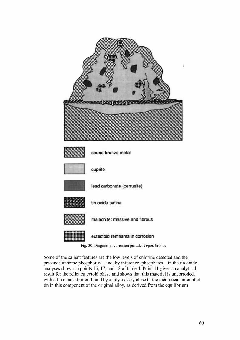
Fig. 30. Diagram of corrosion pustule, Togati bronze
Some of the salient features are the low levels of chlorine detected and the presence of some phosphorus—and, by inference, phosphates—in the tin oxide analyses shown in points 16, 17, and 18 of table 4. Point 11 gives an analytical result for the relict eutectoid phase and shows that this material is uncorroded, with a tin concentration found by analysis very close to the theoretical amount of tin in this component of the original alloy, as derived from the equilibrium
60
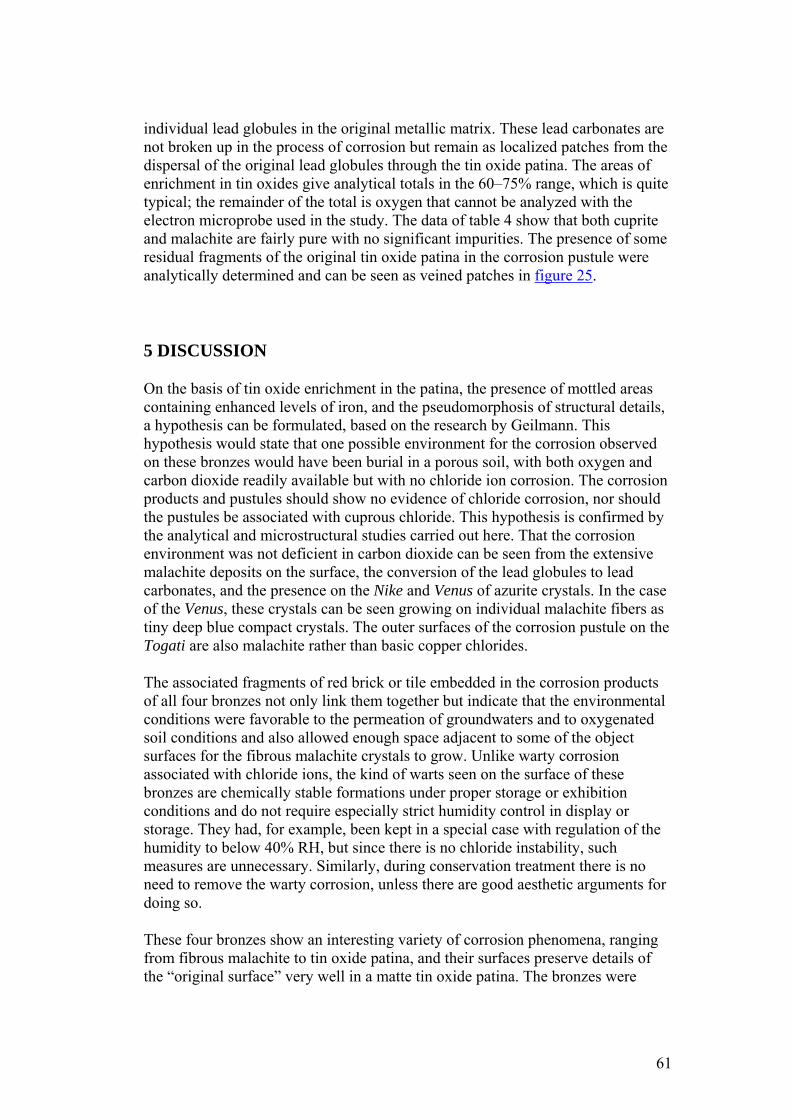
individual lead globules in the original metallic matrix. These lead carbonates are not broken up in the process of corrosion but remain as localized patches from the dispersal of the original lead globules through the tin oxide patina. The areas of enrichment in tin oxides give analytical totals in the 60–75% range, which is quite typical; the remainder of the total is oxygen that cannot be analyzed with the electron microprobe used in the study. The data of table 4 show that both cuprite and malachite are fairly pure with no significant impurities. The presence of some residual fragments of the original tin oxide patina in the corrosion pustule were analytically determined and can be seen as veined patches in figure 25.
5 DISCUSSION
On the basis of tin oxide enrichment in the patina, the presence of mottled areas containing enhanced levels of iron, and the pseudomorphosis of structural details, a hypothesis can be formulated, based on the research by Geilmann. This hypothesis would state that one possible environment for the corrosion observed on these bronzes would have been burial in a porous soil, with both oxygen and carbon dioxide readily available but with no chloride ion corrosion. The corrosion products and pustules should show no evidence of chloride corrosion, nor should the pustules be associated with cuprous chloride. This hypothesis is confirmed by the analytical and microstructural studies carried out here. That the corrosion environment was not deficient in carbon dioxide can be seen from the extensive malachite deposits on the surface, the conversion of the lead globules to lead carbonates, and the presence on the Nike and Venus of azurite crystals. In the case of the Venus, these crystals can be seen growing on individual malachite fibers as tiny deep blue compact crystals. The outer surfaces of the corrosion pustule on the Togati are also malachite rather than basic copper chlorides.
The associated fragments of red brick or tile embedded in the corrosion products of all four bronzes not only link them together but indicate that the environmental conditions were favorable to the permeation of groundwaters and to oxygenated soil conditions and also allowed enough space adjacent to some of the object surfaces for the fibrous malachite crystals to grow. Unlike warty corrosion associated with chloride ions, the kind of warts seen on the surface of these bronzes are chemically stable formations under proper storage or exhibition conditions and do not require especially strict humidity control in display or storage. They had, for example, been kept in a special case with regulation of the humidity to below 40% RH, but since there is no chloride instability, such measures are unnecessary. Similarly, during conservation treatment there is no need to remove the warty corrosion, unless there are good aesthetic arguments for doing so.
These four bronzes show an interesting variety of corrosion phenomena, ranging from fibrous malachite to tin oxide patina, and their surfaces preserve details of the “original surface” very well in a matte tin oxide patina. The bronzes were
61
mechanically cleaned during conservation, revealing this fine detail, but they were also treated with a respect for the preservation of corrosion and associated material overlying the fine patina. It is easy, with hindsight, to criticize earlier methods for the conservation of archaeological bronzes, such as electrolytic cleaning, glass-bead air-abrasion techniques, use of chemical stripping reagents or removal of outer layers of the patina, sometimes to reveal a cuprite surface. An analogy is frequently made to medicine, where earlier treatment techniques have been discarded. The only difficulty is in gauging the health of the patient. We know that we overtreated the patient in the past, but there is still a danger that by cleaning and removal of corrosion, we are losing precious clues to association, burial, and environment. Practices in this respect are not uniform throughout the conservation profession. In any event, a variety of treatment options are available to the conservator, depending on the object; the advantages and disadvantages of cleaning have to be evaluated carefully. This paper could not have been written if the bronzes had been cleaned of all extraneous corrosion products.
ACKNOWLEDGEMENTS
Thanks are due to Bruce Christman, head, Conservation Department, Cleveland Museum of Art, for allowing Lisbet Thoresen, associate conservator, Department of Antiquities Conservation, J. Paul Getty Museum, and me to study and sample the Cleveland Nike; to Eric Doehne for carrying out the many microprobe analyses; to WestCoast Analytical Services for performing the ICP-MS analyses; to Jerry Podany, head, Department of Antiquities Conservation, J. Paul Getty Museum, for commenting on the manuscript; and to Karen Manchester, Antiquities Curatorial Department, J. Paul Getty Museum. Special thanks are due to Eva Sander, conservator, who assisted in preparing an English translation of the paper by Geilmann in 1986.
REFERENCES
Bassett, J., and T. W.Chase.1993. Considerations in the cleaning of ancient Chinese bronze vessels. In Ancient and historic metals: Conservation and technology,ed.D. A.Scott, J.Podany, and B.Considine. Los Angeles: Getty Conservation Institute. In press Chase, T. W.1993. Chinese bronzes: Casting, finishing, patination, and corrosion. In Ancient and historic metals: Conservation and technology, ed.D. A.Scott, J.Podany, and B.Considine. Los Angeles: Getty Conservation Institute. In press. Christman, B. 1988. Condition report for the Nike. In The Gods delight: The human figure in classical bronze,ed.A. P.Kozloff and D. G.Mitten. Cleveland: Cleveland Museum of Art.
62
Museum of Art. Craddock, P. T.1983. Three thousand years of copper alloys: From the Bronze Age to the Industrial Revolution. In Application of science in examination of works of art, ed.P. A.England and L.van Zelst. Boston: Museum of Fine Arts. 59–67. Cushing, D.1965. Principles of corrosion applicable to ancient metals and methods of identifying corrosion products. In Application of science in examination of works of art. Boston: Museum of Fine Arts. 53–65. Fabrizi, M., and D. A.Scott. 1987. Unusual copper corrosion products and problems of identity. In Recent advances in the conservation and analysis of artifacts, comp. J.Black. London: Summer Schools Press. 131–33. Fink, C. G., and E. P.Polushkin.1936. Microscopic study of ancient bronze and copper. Transactions of the American Institute of Mining and Metallurgy122:90–120. Geilmann, W. von1956. Verwitterung von bronzen im Sandboden. Angewandte Chemie68: 201–12. Gettens, R. J.1969. The Freer Chinese bronzes 2. Technical Studies. Washington: Freer Gallery of Art, Smithsonian Institution. Gettens, R. J., and E. W.FitzHugh.1974. Malachite and green verditer. Studies in Conservation19: 2–23. Graedel, T. E.1987. Copper patinas formed in the atmosphere. Part 2. A qualitative assessment of mechanisms. Corrosion Science7:685–94 Herrmann, J. J., Jr.1988. Catalog entries 63, 64, 65. In The gods delight: The human figure in classical bronze, ed.A. P.Kozloff and D. G.Mitten. Cleveland: Cleveland Museum of Art. Jedrzejewska, H.1976. A corroded Egyptian bronze: Cleaning and discoveries. Studies in Conservation21: 101–14. Lucey, V. F.1972. Developments leading to the present understanding of the mechanism of pitting corrosion of copper. British Corrosion Journal7:36–41 Organ, R. M.1963. The examination and treatment of bronze antiquities. In Recent advances in conservation, ed.GarryThomson. London: Butterworths. 107–8. Organ, R. M.1977. The current status of the treatment of corroded metal artifacts. In Corrosion and metal artifacts, ed.B. FloydBrown et al. NBS Special Publication no. 479. Washington, D.C.: U.S. Department of Commerce. 107–42. Palache, C., H.Berman, and C.Frondel, eds. 1951. Dana's system of mineralogy, vol. 2. New York: JohnWiley. 252–53. Podany, J.1988. Condition reports for the Roma, Togati, and Demeter. In The gods delight: The human figure in classical bronze,ed.A. P.Kozloff and D. G.Mitten. Cleveland: Cleveland Museum of Art. Robbiola, L.1990. Caractérisation de l'alteration des bronzes archéologiques enfous à partir d'un corpus d'objets de l'age du bronze. Mécanismes de la corrosion. Doctoral thesis, University of Paris.
63
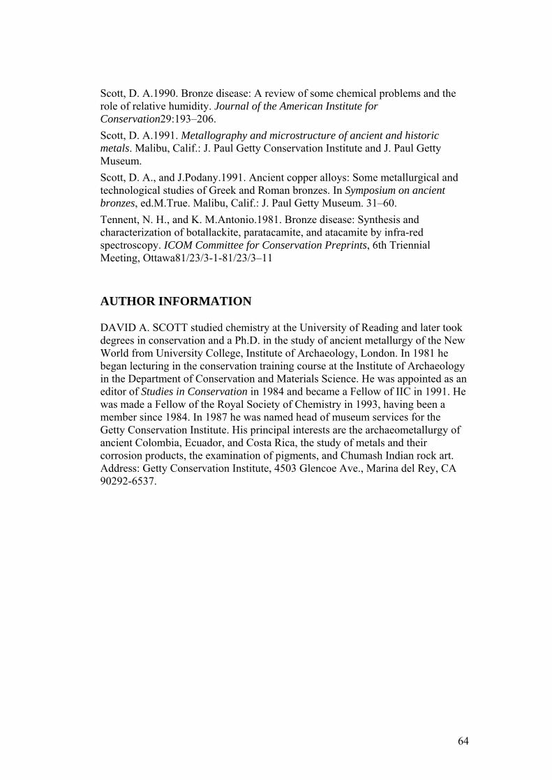
Scott, D. A.1990. Bronze disease: A review of some chemical problems and the role of relative humidity. Journal of the American Institute for Conservation29:193–206. Scott, D. A.1991. Metallography and microstructure of ancient and historic metals. Malibu, Calif.: J. Paul Getty Conservation Institute and J. Paul Getty Museum. Scott, D. A., and J.Podany.1991. Ancient copper alloys: Some metallurgical and technological studies of Greek and Roman bronzes. In Symposium on ancient bronzes, ed.M.True. Malibu, Calif.: J. Paul Getty Museum. 31–60. Tennent, N. H., and K. M.Antonio.1981. Bronze disease: Synthesis and characterization of botallackite, paratacamite, and atacamite by infra-red spectroscopy. ICOM Committee for Conservation Preprints, 6th Triennial Meeting, Ottawa81/23/3-1-81/23/3–11
AUTHOR INFORMATION
DAVID A. SCOTT studied chemistry at the University of Reading and later took degrees in conservation and a Ph.D. in the study of ancient metallurgy of the New World from University College, Institute of Archaeology, London. In 1981 he began lecturing in the conservation training course at the Institute of Archaeology in the Department of Conservation and Materials Science. He was appointed as an editor of Studies in Conservation in 1984 and became a Fellow of IIC in 1991. He was made a Fellow of the Royal Society of Chemistry in 1993, having been a member since 1984. In 1987 he was named head of museum services for the Getty Conservation Institute. His principal interests are the archaeometallurgy of ancient Colombia, Ecuador, and Costa Rica, the study of metals and their corrosion products, the examination of pigments, and Chumash Indian rock art. Address: Getty Conservation Institute, 4503 Glencoe Ave., Marina del Rey, CA 90292-6537.
64
JAIC 1997, Volume 36, Number 1, Article 2 (pp. 17 to 29)
A TRANSLUCENT WAX-RESIN FILL MATERIAL FOR THE COMPENSATION OF LOSSES IN OBJECTS
SUSANNE GÄNSICKE, & JOHN W. HIRX
ABSTRACT—A thermoplastic synthetic wax-resin mixture was developed by John W. Burke and Steve Colton for compensating losses in objects made from translucent materials. This material is an aesthetically pleasing and reversible alternative to other compensation materials such as epoxy and polyester resins or waxes. The authors describe how the various components of the mixture, including polyvinyl acetate (PVAC) AYAC, ethylene acrylic acid copolymers A-C 540 and 580, antioxidants Irganox 1076 or 1035, and a variety of possible fillers can be melted together, applied to areas of loss, and sculpted to shape.
1 INTRODUCTION
The compensation of losses in objects made from translucent materials such as alabaster, marble, calcite, diorite, and anhydrite has always been challenging. Traditionally waxes, polyester, epoxy, and acrylic resins bulked with a variety of materials and coloring agents to imitate stone have been applied to areas of loss, but to date no satisfactory solution has been found. Waxes tend to collect dust and dirt. Both polyester resins and epoxies are toxic and noxious. If applied directly to the area of loss, they can migrate into and catalyze within the stone. With time, both materials will yellow and can lead to internal staining. These resins are difficult to remove; they only swell in solvents rather than dissolving, and swelling can cause cracking and delamination of the object. The application of lowviscosity synthetic resins sometimes requires the creation of complicated molds. If multicolored or banded fills are required, the work becomes even more complicated.
About 10 years ago John Burke, Oakland Museum, Oakland, California, and Steve Colton, Los Angeles County Museum of Art (LACMA), experimented with thermoplastic fill materials to compensate losses in alabaster objects. The formula of the wax-resin1 presented here was the outcome of their work and has been used by conservators in several museums since. This paper attempts to compile the available information about the wax-resin components and provides further discussion on its applications and limitations. The mixture consists of polyvinyl acetate (PVAC) AYAC, ethylene acrylic acid (EAA) copolymers A-C 540 and 580, antioxidants Irganox 1076 or 1035, dry pigments, marble powder, and other additives, which are melted together (fig. 1).
65
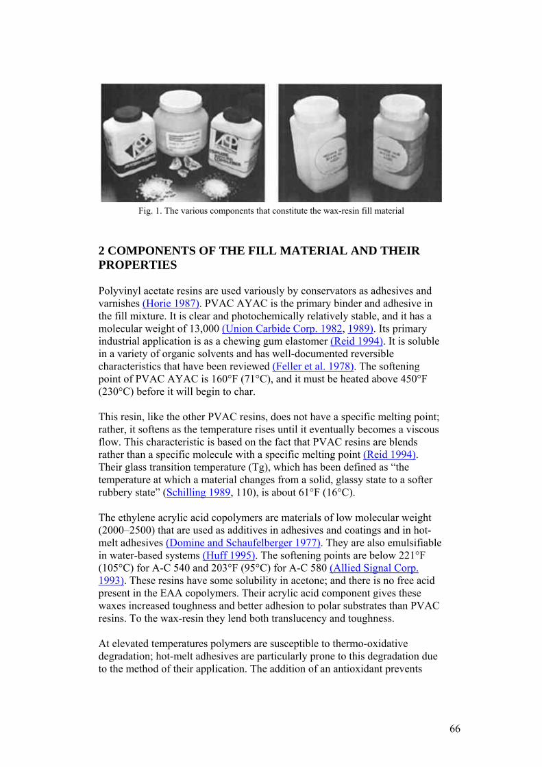
Fig. 1. The various components that constitute the wax-resin fill material
2 COMPONENTS OF THE FILL MATERIAL AND THEIR PROPERTIES
Polyvinyl acetate resins are used variously by conservators as adhesives and varnishes (Horie 1987). PVAC AYAC is the primary binder and adhesive in the fill mixture. It is clear and photochemically relatively stable, and it has a molecular weight of 13,000 (Union Carbide Corp. 1982, 1989). Its primary industrial application is as a chewing gum elastomer (Reid 1994). It is soluble in a variety of organic solvents and has well-documented reversible characteristics that have been reviewed (Feller et al. 1978). The softening point of PVAC AYAC is 160°F (71°C), and it must be heated above 450°F (230°C) before it will begin to char.
This resin, like the other PVAC resins, does not have a specific melting point; rather, it softens as the temperature rises until it eventually becomes a viscous flow. This characteristic is based on the fact that PVAC resins are blends rather than a specific molecule with a specific melting point (Reid 1994). Their glass transition temperature (Tg), which has been defined as “the temperature at which a material changes from a solid, glassy state to a softer rubbery state” (Schilling 1989, 110), is about 61°F (16°C).
The ethylene acrylic acid copolymers are materials of low molecular weight (2000–2500) that are used as additives in adhesives and coatings and in hot-melt adhesives (Domine and Schaufelberger 1977). They are also emulsifiable in water-based systems (Huff 1995). The softening points are below 221°F (105°C) for A-C 540 and 203°F (95°C) for A-C 580 (Allied Signal Corp. 1993). These resins have some solubility in acetone; and there is no free acid present in the EAA copolymers. Their acrylic acid component gives these waxes increased toughness and better adhesion to polar substrates than PVAC resins. To the wax-resin they lend both translucency and toughness.
At elevated temperatures polymers are susceptible to thermo-oxidative degradation; hot-melt adhesives are particularly prone to this degradation due to the method of their application. The addition of an antioxidant prevents
66
yellowing of the wax-resin at high temperatures, either while melting or on the spatula tip.
There are two basic classes of stabilizers: primary or chain-terminating antioxidants and secondary hydroperoxide-decomposing antioxidants (Ciba Geigy Corp. 1990, 1993; Earhart et al. 1994). Primary antioxidants have also been described as radical scavengers because they react with peroxy and alkoxy radicals to form phenoxy radicals, which are relatively stable (de la Rie 1988a, 1988b). The Irganox 1076, a primary hindered phenolic antioxidant, was chosen for this formula because its melting point of 50–55°C is below the formulating temperature of the blend. Irganox 1035, another primary hindered phenolic antioxidant, has also been used in this formula. It has a sulfur bridge that provides peroxide decomposition capability in addition to standard antioxidant functionality. It is also a slightly larger molecule than Irganox 1076 and has a melting point of 145–54°F (63–68°C); but de la Rie (1988a) cautioned that the use of sulfur compounds, such as Irganox 1035, in metal ion-containing materials might lead to darkening.
As Burke (1983) observed, the ratio of components can be altered according to the desired qualities of the fill material. He increased the PVAC AYAC content to harden the blend and to increase gloss, melting point, and viscosity. He noticed that increasing the EAA content increases the waxiness of the blend but also decreases the cold flow while simultaneously decreasing the melt viscosity. A-C 580 is softer and more adhesive than the A-C 540; varying the 540/580 proportion, therefore, affects those properties. Burke also experimented with adding an ultraviolet (UV) absorber, which appeared to prevent yellowing, but the UV absorber (Uvinul D-49) he used was strongly colored and imparted a slight tint of its own.
3 PRELIMINARY NOTES ON AGING PROPERTIES OF THE FILL MATERIAL
Degradation of polymers is complex and depends on numerous factors (McNeill 1992). To date we have observations only on color fastness and physical stability of the fill material;2 we also have some indication of whether or not the wax-resin shows cold flow relative to the individual components.
The PVAC component in the wax-resin has been shown to be a relatively stable material and was classified by Feller (1978) as a class A material.3 When Burke conducted the blue-wool test on the EAA A-C 540, he found that it actually bleached slightly. A recent article by Down et al. (1996) describes PVAC AYAC as having a “fair resistance to yellowing,” but also confirmed its emission of small amounts of acetic acid.
We do not know the glass transition temperature of the fill material, but the combination of polymers probably affect their respective Tgs. The PVAC's Tg
67

goes up slightly, and the EAA's melting point goes down. It has been suggested that fillers such as pigments and marble powder may behave like tiny hurdles that the polymers have to move around, which slow them down (Schlumpf 1990). While one very large fill of the fills described below has changed its shape, all the others have remained apparently unchanged over the course of a decade.
To further investigate the Tg of the material, a batch of pure PVAC AYAC and a batch of the fill material were made in the Objects Conservation Laboratory at LACMA and placed in dated containers on January 10, 1994, where they are being monitored. The PVAC has already begun to move, but the wax-resin has not. Another test being conducted at LACMA with a starting date of April 15, 1995, involves placing a 50 gm weight on a block of wax-resin to see if it displaces the resin. No movement has occurred to date (July 12, 1996). Certainly the ongoing tests described above are rudimentary, and many more tests will have to be done to examine the possible degradation of the material.
4 USE OF THE WAX-RESIN FOR TREATMENTS
4.1 PREPARATION OF THE MATERIAL
The following formula has been used for numerous treatments in several conservation laboratories: 9 parts PVAC AYAC, 3 parts A-C 540, 1 part A-C 580, and 0.5% by weight Irganox 1076 or 1035.
Starting with the PVAC, these materials are melted together on a hot plate or wax pot, or in a well-controlled oven, at the lowest possible temperature. When the PVAC is melted, the antioxidant and thermal inhibitor Irganox is added. The EAA resins are slowly stirred into the hot melt. The components are not completely miscible; rather, they are slightly incompatible. Discoloration and separation can occur if the temperature is too high or if the mixture is not stirred enough. Separation is easily recognizable, for the PVAC floats in translucent bubbles on the surface of the mixture; stirring will reverse this situation. If no pigments or fillers are added, the mix becomes a translucent, light grayish white, somewhat glassy material. Dry pigments can be added as needed (fig. 2). If the treatment requires the use of small strips of cold wax- resin, the melted mass can be poured into strips on Mylar or glass and allowed to cool (fig. 3).
68
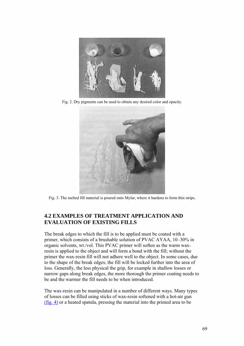
Fig. 2. Dry pigments can be used to obtain any desired color and opacity.
Fig. 3. The melted fill material is poured onto Mylar, where it hardens to form thin strips.
4.2 EXAMPLES OF TREATMENT APPLICATION AND EVALUATION OF EXISTING FILLS
The break edges to which the fill is to be applied must be coated with a primer, which consists of a brushable solution of PVAC AYAA, 10–30% in organic solvents, wt./vol. This PVAC primer will soften as the warm wax-resin is applied to the object and will form a bond with the fill; without the primer the wax-resin fill will not adhere well to the object. In some cases, due to the shape of the break edges, the fill will be locked further into the area of loss. Generally, the less physical the grip, for example in shallow losses or narrow gaps along break edges, the more thorough the primer coating needs to be and the warmer the fill needs to be when introduced.
The wax-resin can be manipulated in a number of different ways. Many types of losses can be filled using sticks of wax-resin softened with a hot-air gun (fig. 4) or a heated spatula, pressing the material into the primed area to be
69
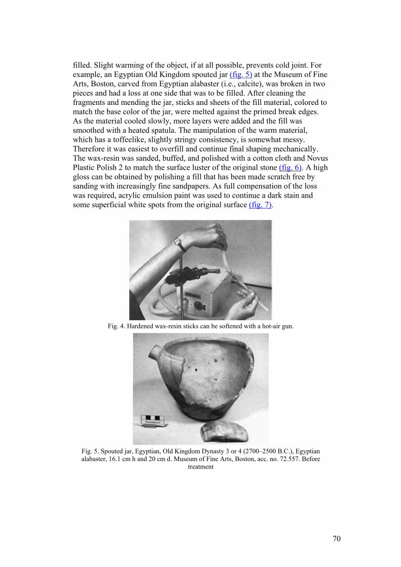
filled. Slight warming of the object, if at all possible, prevents cold joint. For example, an Egyptian Old Kingdom spouted jar (fig. 5) at the Museum of Fine Arts, Boston, carved from Egyptian alabaster (i.e., calcite), was broken in two pieces and had a loss at one side that was to be filled. After cleaning the fragments and mending the jar, sticks and sheets of the fill material, colored to match the base color of the jar, were melted against the primed break edges. As the material cooled slowly, more layers were added and the fill was smoothed with a heated spatula. The manipulation of the warm material, which has a toffeelike, slightly stringy consistency, is somewhat messy. Therefore it was easiest to overfill and continue final shaping mechanically. The wax-resin was sanded, buffed, and polished with a cotton cloth and Novus Plastic Polish 2 to match the surface luster of the original stone (fig. 6). A high gloss can be obtained by polishing a fill that has been made scratch free by sanding with increasingly fine sandpapers. As full compensation of the loss was required, acrylic emulsion paint was used to continue a dark stain and some superficial white spots from the original surface (fig. 7).
Fig. 4. Hardened wax-resin sticks can be softened with a hot-air gun.
Fig. 5. Spouted jar, Egyptian, Old Kingdom Dynasty 3 or 4 (2700–2500 B.C.), Egyptian alabaster, 16.1 cm h and 20 cm d. Museum of Fine Arts, Boston, acc. no. 72.557. Before
treatment
70
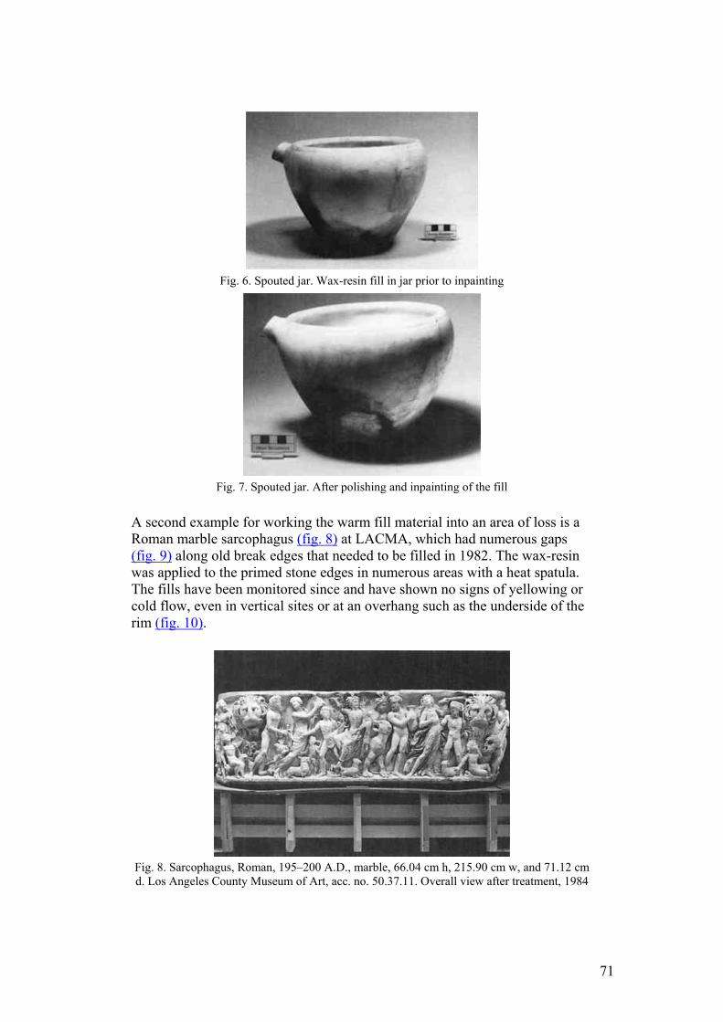
Fig. 6. Spouted jar. Wax-resin fill in jar prior to inpainting
Fig. 7. Spouted jar. After polishing and inpainting of the fill
A second example for working the warm fill material into an area of loss is a Roman marble sarcophagus (fig. 8) at LACMA, which had numerous gaps (fig. 9) along old break edges that needed to be filled in 1982. The wax-resin was applied to the primed stone edges in numerous areas with a heat spatula. The fills have been monitored since and have shown no signs of yellowing or cold flow, even in vertical sites or at an overhang such as the underside of the rim (fig. 10).
Fig. 8. Sarcophagus, Roman, 195–200 A.D., marble, 66.04 cm h, 215.90 cm w, and 71.12 cm d. Los Angeles County Museum of Art, acc. no. 50.37.11. Overall view after treatment, 1984
71
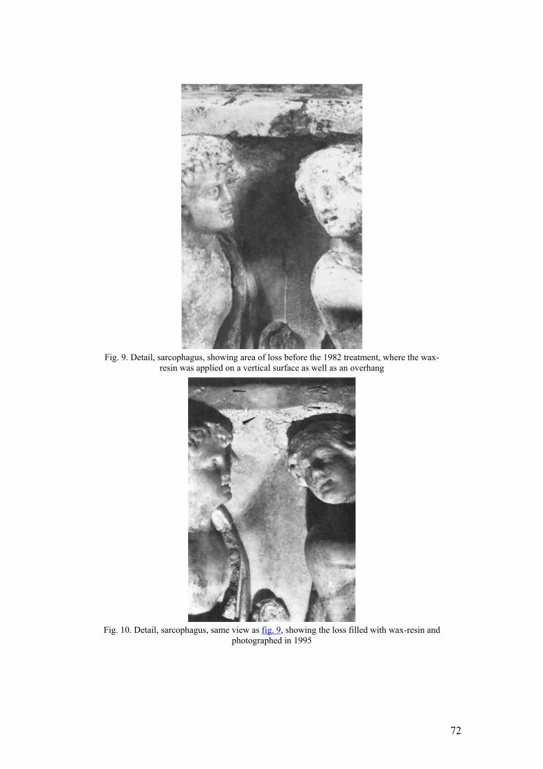
Fig. 9. Detail, sarcophagus, showing area of loss before the 1982 treatment, where the wax-
resin was applied on a vertical surface as well as an overhang
Fig. 10. Detail, sarcophagus, same view as fig. 9, showing the loss filled with wax-resin and
photographed in 1995
72
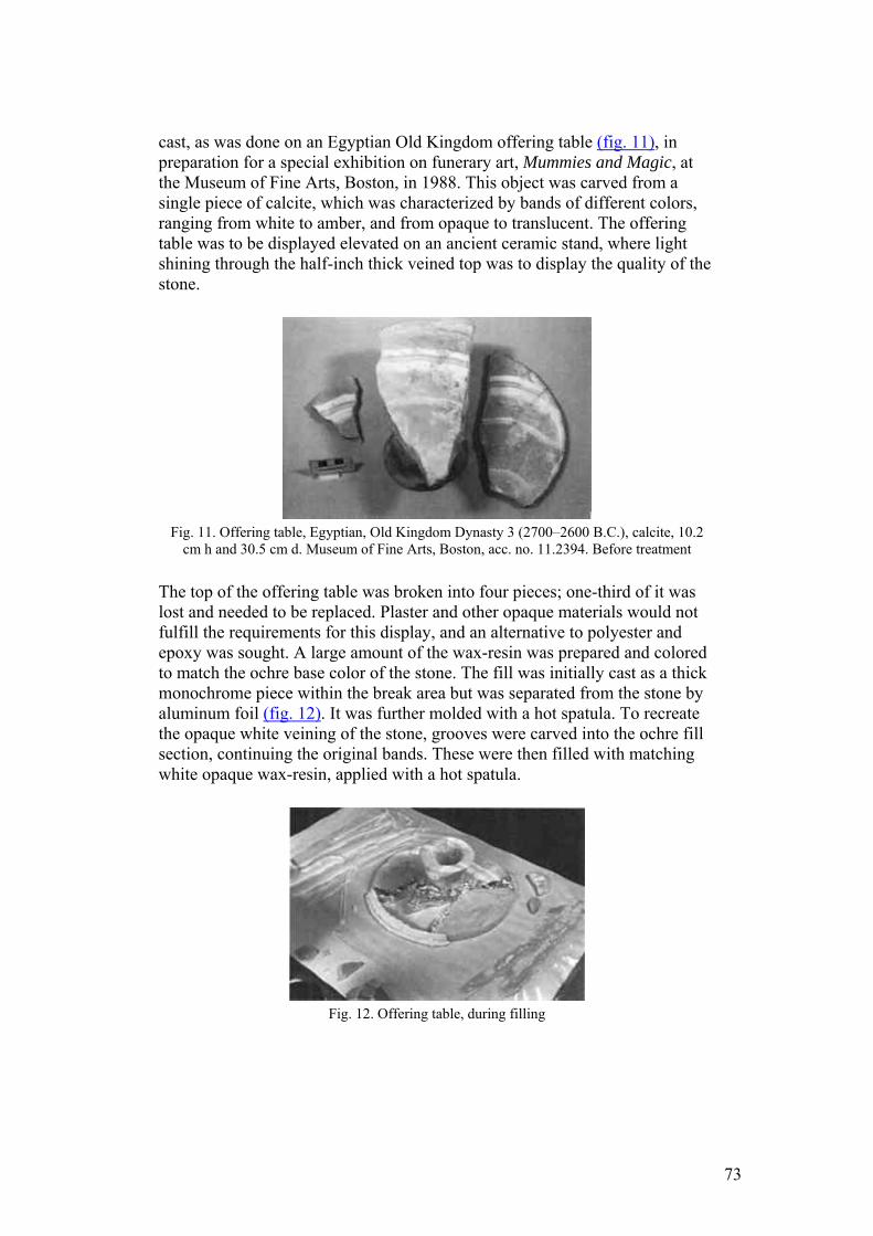
cast, as was done on an Egyptian Old Kingdom offering table (fig. 11), in preparation for a special exhibition on funerary art, Mummies and Magic, at the Museum of Fine Arts, Boston, in 1988. This object was carved from a single piece of calcite, which was characterized by bands of different colors, ranging from white to amber, and from opaque to translucent. The offering table was to be displayed elevated on an ancient ceramic stand, where light shining through the half-inch thick veined top was to display the quality of the stone.
Fig. 11. Offering table, Egyptian, Old Kingdom Dynasty 3 (2700–2600 B.C.), calcite, 10.2
cm h and 30.5 cm d. Museum of Fine Arts, Boston, acc. no. 11.2394. Before treatment
The top of the offering table was broken into four pieces; one-third of it was lost and needed to be replaced. Plaster and other opaque materials would not fulfill the requirements for this display, and an alternative to polyester and epoxy was sought. A large amount of the wax-resin was prepared and colored to match the ochre base color of the stone. The fill was initially cast as a thick monochrome piece within the break area but was separated from the stone by aluminum foil (fig. 12). It was further molded with a hot spatula. To recreate the opaque white veining of the stone, grooves were carved into the ochre fill section, continuing the original bands. These were then filled with matching white opaque wax-resin, applied with a hot spatula.
Fig. 12. Offering table, during filling
73
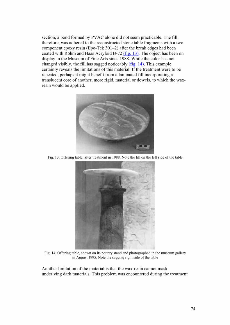
section, a bond formed by PVAC alone did not seem practicable. The fill, therefore, was adhered to the reconstructed stone table fragments with a two component epoxy resin (Epo-Tek 301–2) after the break edges had been coated with Röhm and Haas Acryloid B-72 (fig. 13). The object has been on display in the Museum of Fine Arts since 1988. While the color has not changed visibly, the fill has sagged noticeably (fig. 14). This example certainly reveals the limitations of this material. If the treatment were to be repeated, perhaps it might benefit from a laminated fill incorporating a translucent core of another, more rigid, material or dowels, to which the wax-resin would be applied.
Fig. 13. Offering table, after treatment in 1988. Note the fill on the left side of the table
Fig. 14. Offering table, shown on its pottery stand and photographed in the museum gallery
in August 1995. Note the sagging right side of the table
Another limitation of the material is that the wax-resin cannot mask underlying dark materials. This problem was encountered during the treatment
74
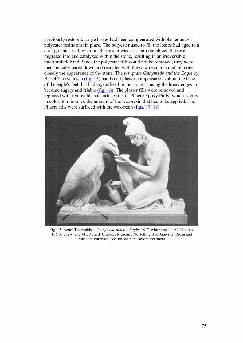
previously restored. Large losses had been compensated with plaster and/or polyester resins cast in place. The polyester used to fill the losses had aged to a dark greenish yellow color. Because it was cast onto the object, the resin migrated into and catalyzed within the stone, resulting in an irreversible interior dark band. Since the polyester fills could not be removed, they were mechanically pared down and recoated with the wax-resin to simulate more closely the appearance of the stone. The sculpture Ganymede and the Eagle by Bertel Thorwaldsen (fig. 15) had broad plaster compensations about the base of the eagle's feet that had crystallized in the stone, causing the break edges to become sugary and friable (fig. 16). The plaster fills were removed and replaced with removable subsurface fills of Pliacre Epoxy Putty, which is gray in color, to minimize the amount of the wax-resin that had to be applied. The Pliacre fills were surfaced with the wax-resin (figs. 17, 18).
Fig. 15. Bertel Thorwaldsen, Ganymede and the Eagle, 1817, white marble, 82.23 cm h, 106.05 cm w, and 41.28 cm d. Chrysler Museum, Norfolk, gift of James H. Ricau and
Museum Purchase, acc. no. 86.525. Before treatment
75
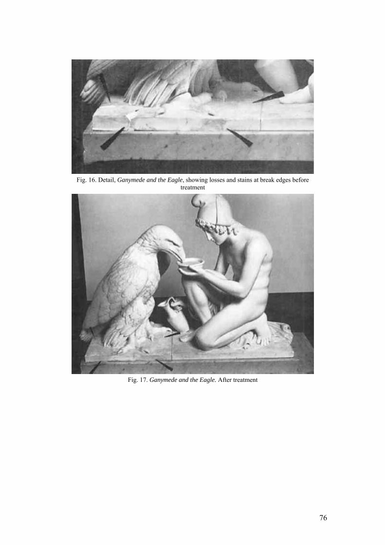
Fig. 16. Detail, Ganymede and the Eagle, showing losses and stains at break edges before
treatment
Fig. 17. Ganymede and the Eagle. After treatment
76
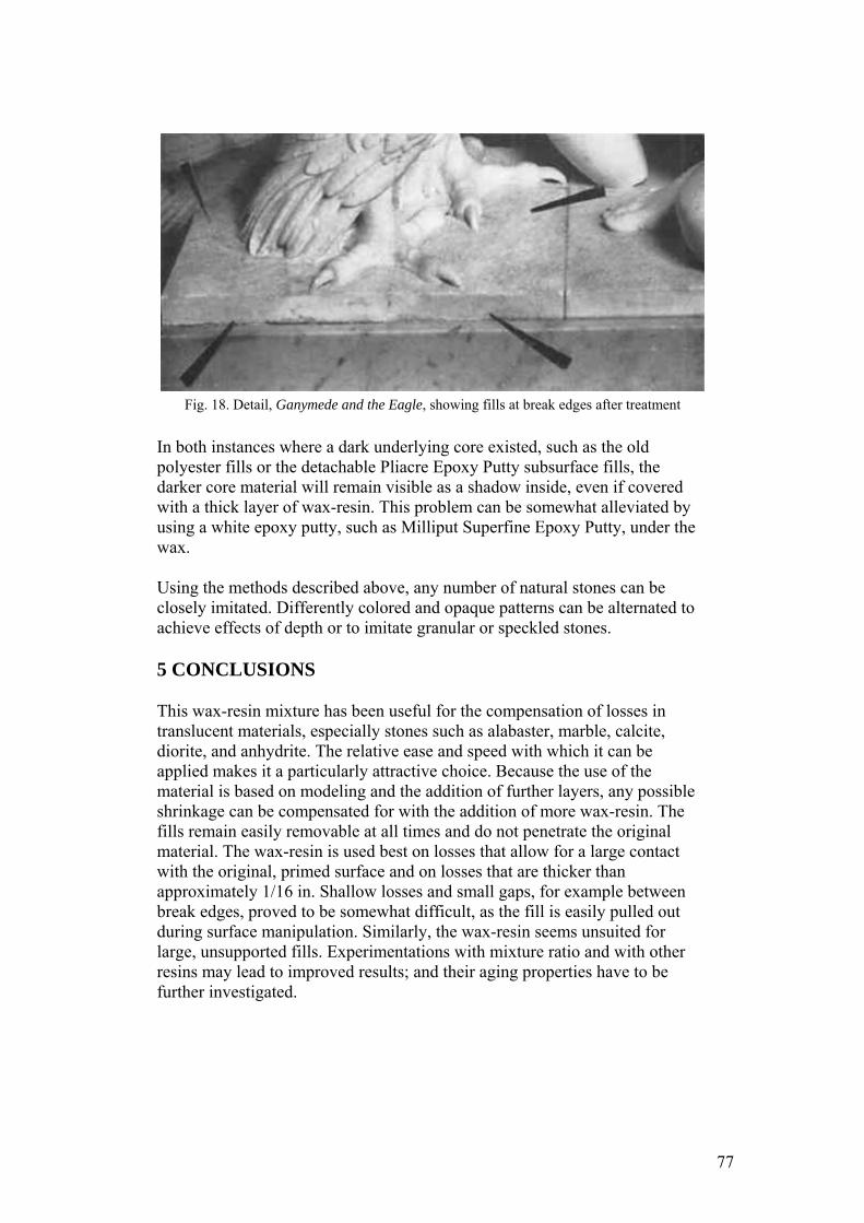
Fig. 18. Detail, Ganymede and the Eagle, showing fills at break edges after treatment
In both instances where a dark underlying core existed, such as the old polyester fills or the detachable Pliacre Epoxy Putty subsurface fills, the darker core material will remain visible as a shadow inside, even if covered with a thick layer of wax-resin. This problem can be somewhat alleviated by using a white epoxy putty, such as Milliput Superfine Epoxy Putty, under the wax.
Using the methods described above, any number of natural stones can be closely imitated. Differently colored and opaque patterns can be alternated to achieve effects of depth or to imitate granular or speckled stones.
5 CONCLUSIONS
This wax-resin mixture has been useful for the compensation of losses in translucent materials, especially stones such as alabaster, marble, calcite, diorite, and anhydrite. The relative ease and speed with which it can be applied makes it a particularly attractive choice. Because the use of the material is based on modeling and the addition of further layers, any possible shrinkage can be compensated for with the addition of more wax-resin. The fills remain easily removable at all times and do not penetrate the original material. The wax-resin is used best on losses that allow for a large contact with the original, primed surface and on losses that are thicker than approximately 1/16 in. Shallow losses and small gaps, for example between break edges, proved to be somewhat difficult, as the fill is easily pulled out during surface manipulation. Similarly, the wax-resin seems unsuited for large, unsupported fills. Experimentations with mixture ratio and with other resins may lead to improved results; and their aging properties have to be further investigated.
77
ACKNOWLEDGEMENTS
Thanks to John Burke and Steve Colton for discussing their treatments and research and for supporting this publication. The late Jane Carpenter-Poliquin should be remembered especially for introducing the wax-resin to the Straus Center for Conservation and Technical Studies, Harvard University Art Museums. Carol Warner, National Park Service, Cultural Resources Center, Lowell, Massachusetts, was first to experiment with the material and to use it at the Museum of Fine Arts, Boston. Arthur Beale and Timothy Kendall, both of the MFA, and Pieter Meyers, Los Angeles County Museum of Art, helped to edit the paper.
NOTES
. The term “wax” in “wax-resin” is used throughout the article in reference to ethylene acrylic acid copolymer (EAA). “Wax” is a rather loose term applied to a variety of substances consisting of hydro-carbons and sharing a number of characteristics such as waxy feel. Furthermore, most of them are relatively solid at room temperature, liquefy with increasing temperatures, and will solidify when cooled again.
NOTES
. Burke has observed that some of the earliest samples he used have yellowed, a process he attributes either to lack of an antioxidant or to overheating at the time. He also subjected samples of the wax-resin to accelerated aging and then separated PVAC from EAA by melting. He noted that it appeared the PVAC component in fact had yellowed. Based on this observation, Union Carbide recommended adding a cycloaliphatic epoxy resin (ERL–4221) as a stabilizer to the PVAC. Samples of wax-resin prepared with this additive do not seem to have yellowed over 10 years. Burke has continued to use the epoxy resin as an antioxidant substitute for Irganox when he wanted to manipulate the hardness of the wax-resin. The cycloaliphatic epoxy resin is a liquid; Irganox is a solid. The inclusion of the epoxy resin results in a flexible wax-resin material. The addition of Irganox results in a material that is hard. The addition of either antioxidant is the same: 0.5% by weight. Burke is exploring other conservation applications of the EAA copolymers.
NOTES
. Feller published a grading system for conservation materials and their expected photo-stability based on the blue-wool test using the International Standard Organization R105 blue wool standard 6 for photochemical stability, in which the degree of fading of a sample of blue wool has been quantified. Under most conditions, conservators prefer to use a class A material, which, based on annual museum light levels, should last for 100 years or more or suffer no more than 20% loss of its essential properties.
78
REFERENCES
Allied Signal Corp.1993. Product specifications. Specifications 605800227 and 505400227. Burke, J.1983. Personal communication to Billie Milam and Steve Colton. 7969 Sunkist Dr., Oakland, Calif. 94605–3050. Ciba-Geigy Corp.1990. Antioxidants for polyolefins. A350B5M60. Ciba-Geigy Corp.1993Additives for coatings. A-288C7.5M23. de laRie, E. R.1988a. Polymer stabilizers: A survey with reference to possible applications in the conservation field. Studies in Conservation33: 9–22. de laRie, E. R.1988bStable varnishes for old master paintings. Diss. Netherlands: Krips Repro Meppel. Domine, J. D., and R. H.Schaufelberger. 1977. Ethylene copolymer based hot melt adhesives. In Handbook of Adhesives, ed.I.Skeist. New York: Van Nostrand Reinhold Company. 495–506. Down, J. L., M. A.MacDonald, J. T.átreault, and R. S.Williams. 1996. Adhesive testing at the Canadian Conservation Institute: An evaluation of selected poly(vinyl acetate) and acrylic adhesives. Studies in Conservation41: 19–44. Earhart, N., A.Patel, and G.Knobloch. 1994. Thermal stabilization of adhesives. In Handbook of adhesive technology, ed. A.Pizzi and K. L.Mittal. New York: Marcel Dekker. 241–55. Feller, R.1978. Standards in the evaluation of thermoplastic resins. In ICOM Committee for Conservation preprints, 5th triennial meeting, Zagreb. Paris: ICOM. 16(4): 1. Feller, R., E. H.Jones, and N.Stolow. 1978. On picture varnishes and their solventsOberlin, Ohio: Intermuseum Conservation Association. Horie, C. V.1987. Materials for conservation. London: Butterworths. 92–96. Huff, M.1995. Personal communication. Allied Signal Corp., P.O. Box 2332, Morristown, N.J. 07962–2332. McNeill, I. C.1992Fundamental aspects of polymer degradation. In Polymers in conservation, ed. N. S.Allen, M.Edge, and C. V.Horie. Cambridge: Royal Society of Chemistry. 14–31. Reid, G.1994Personal communication. Technical consultant, Union Carbide Corp., Old Ridgebury Rd., Danbury, Conn. 06817. Schilling, M.1989The glass transition of materials used in conservation. Studies in Conservation34: 110–16. Schlumpf, H. P.1990. Fillers and reinforcement. In Plastic additives handbook: Stabilizers, processing aids, plasticizers, fillers, reinforcements, colorants for thermoplastics, ed. R.Gächter and H.Müller. New York: Oxford University Press. 525–91. Union Carbide Corp.1982. Specialty polymers. F-49563.
79
Union Carbide Corp.1989. Polyvinyl acetate resins for coatings and adhesives. SC–1127.
SOURCES OF MATERIALS
Polyvinyl acetate resins PVAC AYAA and AYAC Union Carbide Corp., Specialty Chemicals and Plastics, Old Ridgebury Road, Danbury, Conn. 06817 Ethylene acrylic acid copolymers A-C 540 and 580 Allied Signal Corp. A-C Performance Additives, P.O. Box 2332, Morristown, N. J. 07962–2332 Irganox, antioxidant and thermal stabilizer Ciba-Geigy Corp. Seven Skyline Dr. 3, Hawthorne, N.Y. 10532–2188 Mylar, polyester film Conservation Materials, Ltd. P.O. Box 2884, Sparks, Nev. 89431 Novus Plastic Polish 2 Novus, Inc., 10425 Hampshire Ave. So., Minneapolis, Minn. 55438 Epo-Tek 301–2 Epoxy Technology, Inc., 14 Fortune Dr., Billerica, Mass. 01821 Pliacre Epoxy Putty Philadelphia Resins Corp., 20 Commerce Dr., Montgomeryville, Pa. 18936 Milliput Superfine Epoxy Putty Milliput Corp., Unit 5, The Marion, Dolgellau, Mid Wales LL40 1UU, United Kingdom Acryloid B-72 Röhm and Haas, Independence Mall West, Philadelphia, Pa. 19105
AUTHOR INFORMATION
SUSANNE GÄNSICKE has been an assistant conservator in the Department of Objects Conservation and Scientific Research at Museum of Fine Arts, Boston, since 1990. In 1987 she received a certificate in archaeological conservation from the Römisch-Germanisches Zentralmuseum, Mainz, Germany. She then served an advanced-level internship at the Museum of Fine Arts, followed by an Andrew W. Mellon Fellowship in Objects Conservation at the Metropolitan Museum of Art. She has worked as site conservator at the New York University Apis Expedition at Memphis, Egypt, and at the BMFA Expedition at Gebel Barkal, Karima, Sudan. She is particularly interested in the technical study of ancient Egyptian and Nubian material culture. Address: Objects Conservation and Scientific Research, Museum of Fine Arts, 465 Huntington Ave., Boston, Mass. 02115.
80

JOHN W. HIRX is currently a research assistant in the Conservation Center of the Los Angeles County Museum of Art, where he pursues research on the preservation of archaeological and decorative silver. He was formerly a contract conservator at the Brooklyn Museum, treating the Egyptian collection prior to a reinstallation of the newly renovated galleries. Address: Conservation Center, Los Angeles County Museum of Art, 5905 Wilshire Blvd., Los Angeles, Calif. 90036.
81
JAIC 1980, Volume 20, Number 1, Article 1 (pp. 03 to 20)
A STUDY OF FRENCH PAINTING CANVASES
Katrina VANDERLIP CARBONNEL
ABSTRACT—A large number of canvas samples from paintings by 116 French artists are analyzed for fiber type and weight. Results are categorized chronologically as well as by artist, and it may be seen that prior to the end of the 18th century, hemp canvases were most common, with linen supplanting hemp by the beginning of the 19th century and cottonlinen blends and cotton making their appearance by the end of the 19th century. The method of fiber analysis is described in an appendix.
1 INTRODUCTION
1.1 SELECTING THE SAMPLES
THE COLLECTION OF SAMPLES used in this study is actually composed of canvas fragments selected from two different sources (see list). In both cases, the cloth samples from the original support of authenticated paintings were chosen to be identified and analyzed. The samples were made up of an eclectic group of canvases from Dutch, English, French, Italian and Spanish paintings. The largest category by far was the French.
The first is a group of fabric samples including both lining and original painting canvases gathered since the 1950s by the Service de la Restauration des Peintures des Musées Nationaux (France). I studied all of those samples that could be traced back to an authentic painting. However, the number of non-French samples did not prove large enough to give an adequate idea of the individual country's use of painting canvases. The non-French samples were, therefore, put aside until other canvas fragments can be studied and added to them to form a body for analysis at least the size of the collection used in this article, which is made of canvases from paintings by 116 different French artists.
The second set of samples I put together from fragments given to me by private painting restorers working in Paris.
1.2 ORIGINS OF THE SAMPLES
THE COLLECTION CAN ALSO be divided into three categories according to the method by which the samples were drawn:
1. From cut tacking margins, taken from relined paintings; 2. From transferred pictures; 3. From the edges of restretched paintings.
1. About 80% of the samples in this survey come from cut tacking margins.
82
The French use a wheat paste lining technique that consolidates as well as lines the painting. However, the edges of a freshly wheat paste lined picture are too stiff to be safely turned over a stretcher. For this reason, the original tacking margins are cut off before the lining process and the paste-free lining canvas border is then used as a tacking margin and wrapped over the stretcher.
2. Approximately 19% of the canvas fragments came from the original cloth support removed during the transfer operation. The practice of transferring paintings to a new support, although now rarely done in France, was unfortunately quite frequently done previously. Generally, the transferred canvases were paintings executed before the nineteenth century. However, many impressionist paintings were transferred halfway through the lining process because the fine linen canvas reacted adversely to the moisture.
3. Only a small number of this study's samples were saved from fragments torn from the edges of restretched pictures.
Part I of this study will briefly describe the method of preparing the samples and how they were identified. Part II will deal with the physical characteristics of the samples studied: fiber type, weave pattern, the weight of the fabrics per square meter, and the thread count. Part III will attempt to describe in general terms the types of canvases used by French artists in the 17th, 18th and 19th centuries, showing that hemp canvases were the most common type of canvas used up to the first quarter of the 19th century, at which time linen fabrics took the lead, and that the disappearance of the use of hemp canvases coincides exactly with the decline in the production of hemp in France which began ca. 1820.
Part IV will describe my conclusions.
2 PART I
2.1 PREPARING THE SAMPLES
2.1.1 CUTTING A SQUARE
THE FIRST STEP in preparing the samples for study was to cut a square piece of canvas from the fragment of cloth removed from the painting. When possible, the squares were 10 cm × 10 cm, which was the case only when dealing with the transferred canvases. The square samples cut from tacking margins were sometimes only 1 cm × 1 cm. The samples are made square to facilitate multiplying their surface area to obtain their weight per square meter. Also, the square gives the same accuracy in counting the threads per centimeter in both the directions of the warp and of the weft; for example, threads counted along 10 cm, then divided by 10 give a more accurate count per centimeter than just counting the threads along one centimeter.
83
2.1.2 CLEANING
THE NEXT STEP in preparing the samples was to remove the remaining dirt, ground, and paint layers. The sample was soaked in water to swell the fibers and to loosen the particles of ground and paint caught in the interstices of the cloth. The particles were then delicately mechanically removed with a scalpel.
2.1.3 RAVELING THE EDGES
THE SQUARES HAD been cut slightly larger than the intended size of the sample. The edges were then raveled off until the sample was the desired size. The raveling was done after the sample was cleaned so that, should a thread ravel off during the cleaning process, it would not affect the final size of the sample. The samples assumed to be hemp or linen were raveled off while wet as these two fibers are stronger when wet, while the samples assumed to be cotton were unraveled when dry. The stronger the thread being raveled off, the easier it was to remove it. The reason the sample was fringed in this way was to facilitate counting the threads; it is less tiring to the eyes to count the threads that make up a fringe then to count those that are part of a woven material.
2.1.4 WEIGHING
THE FRINGE WAS cut off the sample just before it was weighed. The weight of the sample was multiplied in order to obtain the weight per square meter of the canvas.
3 PART II
3.1 FABRIC CHARACTERISTICS
3.1.1 FIBER TYPES
THE THREE FIBER types found in this study of French painting canvases are hemp, linen or flax, and cotton, which were used through the centuries in that order. Figures 1, 2 and 3 show this transition from the use of hemp to the use of linen and finally to the use of cotton. Cotton is easily recognized because it looks like a twisted ribbon under the microscope, unlike hemp and linen which look like bamboo.
Fig. 1. Canvas types by century.
84
Fig. 2. Sample percentages by fiber types, 17th to 20th century.
Fig. 3a and 3b. 140 samples which had exact dates charted by fiber composition.
Linen and hemp have often been confused as the two fibers can only be properly identified by examining their cross-section under the microscope. All the samples studied were identified using the method described by M. C. Gay and R. Monrocq in “Identification des Fibres Textiles Naturelles par Examen Microscopique,” Annales du Laboratoire de Recherche des Musées de France, 1972, p. 16–22 (see Fig. 4 and the Appendix). The change over from the use of hemp painting canvases to the use primarily of linen fabrics was probably effected without the artists of that period really realizing it themselves.
85
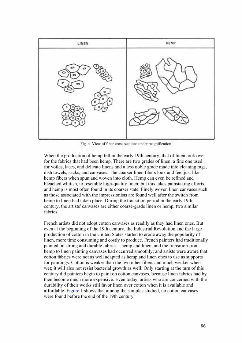
Fig. 4. View of fiber cross sections under magnification.
When the production of hemp fell in the early 19th century, that of linen took over for the fabrics that had been hemp. There are two grades of linen, a fine one used for voiles, laces, and delicate linens and a less noble grade made into cleaning rags, dish towels, sacks, and canvases. The coarser linen fibers look and feel just like hemp fibers when spun and woven into cloth. Hemp can even be refined and bleached whitish, to resemble high-quality linen; but this takes painstaking efforts, and hemp is most often found in its coarser state. Finely woven linen canvases such as those associated with the impressionists are found well after the switch from hemp to linen had taken place. During the transition period in the early 19th century, the artists' canvases are either coarse-grade linen or hemp, two similar fabrics.
French artists did not adopt cotton canvases as readily as they had linen ones. But even at the beginning of the 19th century, the Industrial Revolution and the large production of cotton in the United States started to erode away the popularity of linen, more time consuming and costly to produce. French painters had traditionally painted on strong and durable fabrics—hemp and linen, and the transition from hemp to linen painting canvases had occurred smoothly; and artists were aware that cotton fabrics were not as well adapted as hemp and linen ones to use as supports for paintings. Cotton is weaker than the two other fibers and much weaker when wet; it will also not resist bacterial growth as well. Only starting at the turn of this century did painters begin to paint on cotton canvases, because linen fabrics had by then become much more expensive. Even today, artists who are concerned with the durability of their works still favor linen over cotton when it is available and affordable. Figure 1 shows that among the samples studied, no cotton canvases were found before the end of the 19th century.
86
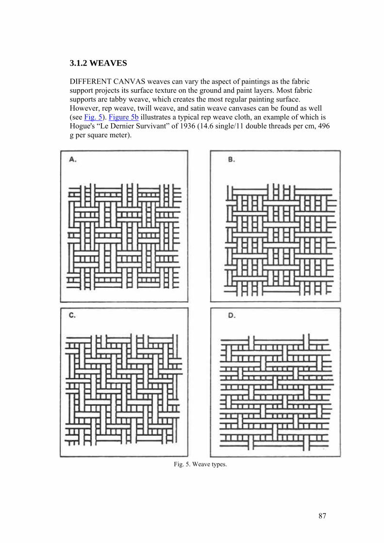
3.1.2 WEAVES
DIFFERENT CANVAS weaves can vary the aspect of paintings as the fabric support projects its surface texture on the ground and paint layers. Most fabric supports are tabby weave, which creates the most regular painting surface. However, rep weave, twill weave, and satin weave canvases can be found as well (see Fig. 5). Figure 5b illustrates a typical rep weave cloth, an example of which is Hogue's “Le Dernier Survivant” of 1936 (14.6 single/11 double threads per cm, 496 g per square meter).
Fig. 5. Weave types.
87
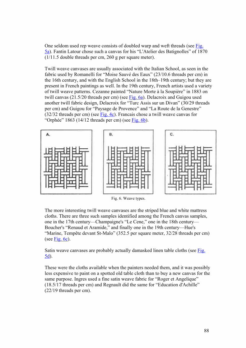
One seldom used rep weave consists of doubled warp and weft threads (see Fig. 5a). Fantin Latour chose such a canvas for his “L'Atelier des Batignolles” of 1870 (1/11.5 double threads per cm, 260 g per square meter).
Twill weave canvases are usually associated with the Italian School, as seen in the fabric used by Romanelli for “Moise Sauvé des Eaux” (23/10.6 threads per cm) in the 16th century, and with the English School in the 18th–19th century; but they are present in French paintings as well. In the 19th century, French artists used a variety of twill weave patterns. Cezanne painted “Nature Morte à la Soupière” in 1883 on twill canvas (21.5/20 threads per cm) (see Fig. 6a). Delacroix and Guigou used another twill fabric design, Delacroix for “Turc Assis sur un Divan” (30/29 threads per cm) and Guigou for “Paysage de Provence” and “La Route de la Genestre” (32/32 threads per cm) (see Fig. 4c). Francais chose a twill weave canvas for “Orphée” 1863 (14/12 threads per cm) (see Fig. 6b).
Fig. 6. Weave types.
The more interesting twill weave canvases are the striped blue and white mattress cloths. There are three such samples identified among the French canvas samples, one in the 17th century—Champaigne's “Le Cene,” one in the 18th century—Boucher's “Renaud et Aramide,” and finally one in the 19th century—Hue's “Marine, Tempête devant St-Malo” (352.5 per square meter, 32/28 threads per cm) (see Fig. 6c).
Satin weave canvases are probably actually damasked linen table cloths (see Fig. 5d).
These were the cloths available when the painters needed them, and it was possibly less expensive to paint on a spotted old table cloth than to buy a new canvas for the same purpose. Ingres used a fine satin weave fabric for “Roger et Angelique” (18.5/17 threads per cm) and Regnault did the same for “Education d'Achille” (22/19 threads per cm).
88
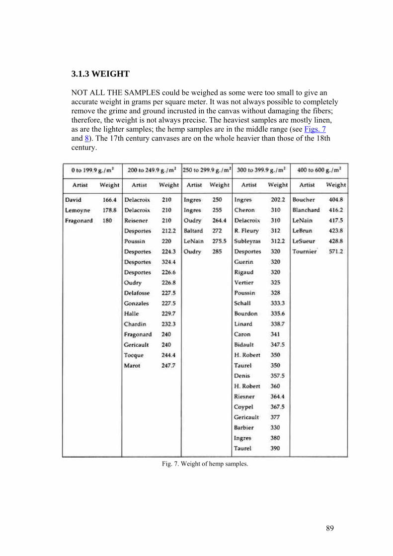
3.1.3 WEIGHT
NOT ALL THE SAMPLES could be weighed as some were too small to give an accurate weight in grams per square meter. It was not always possible to completely remove the grime and ground incrusted in the canvas without damaging the fibers; therefore, the weight is not always precise. The heaviest samples are mostly linen, as are the lighter samples; the hemp samples are in the middle range (see Figs. 7 and 8). The 17th century canvases are on the whole heavier than those of the 18th century.
Fig. 7. Weight of hemp samples.
89

Fig. 8. Weight of linen samples.
3.1.4 THREAD COUNTS
THE COARSENESS or delicacy of a fabric can be described by its thread counts. In the text of Part III, the larger number of threads per centimeter is given first and considered to be the warp, following customary practice. This cannot be definitely ascertained for each sample because the warp and the weft of a fabric can only be identified if the fragment still possesses a portion of its selvage edge. Only one-fifteenth of the samples that still retained a part of their edge had a larger thread count in the direction of the weft.
Only vague conclusions can be drawn on thread counts for different periods of French painting. Specific examples of thread count differences for the 17th, 18th, and 19th centuries will be discussed in Part III. Generally, one may conclude that finer weave hemp canvases were used more in the 18th century than in the 17th century. Also, sometimes gradual variations from finer to coarser and from coarser
90
to finer linen canvases may be noted for specific artists in the 19th century. Other aspects of the thread counts which were studied showed that the variations between the thread counts of the warp and the weft threads indicate how evenly the fabric was woven. These variations are given for hemp canvases in Figure 9 and for linen canvases in Figure 10. The thread counts are divided into categories according to the difference in the thread counts of the warp and of the weft: 0 threads difference, 0.1 to 1 threads difference, 1.1 to 3 threads difference, etc. Figure 8 shows that the more coarsely woven hemp canvases with thread count variations between the warp and the weft threads of more than 3.1 threads per centimeter are from the 18th and 19th centuries, whereas the 17th century hemp canvases are more evenly woven with thread count differences of less than 3 threads per centimeter. Figure 11 indicates that the few linen canvases used before the 19th century cannot be grouped into any one thread count difference category. The chart also shows that certain artists did not choose evenly woven linen throughout their careers. Monet, for example, has an almost equal number of canvases in each of the categories a, b, c and d, as do Corot, Renoir, Sisley, and Van Gogh. Toulouse-Lautrec and Cezanne have more evenly woven canvases in the category b.
Fig. 9. Differences in thread counts for hemp samples.
Fig. 10a and 10b. Differences in thread counts for linen samples, and difference in weave between warps
and wefts of linen samples.
91
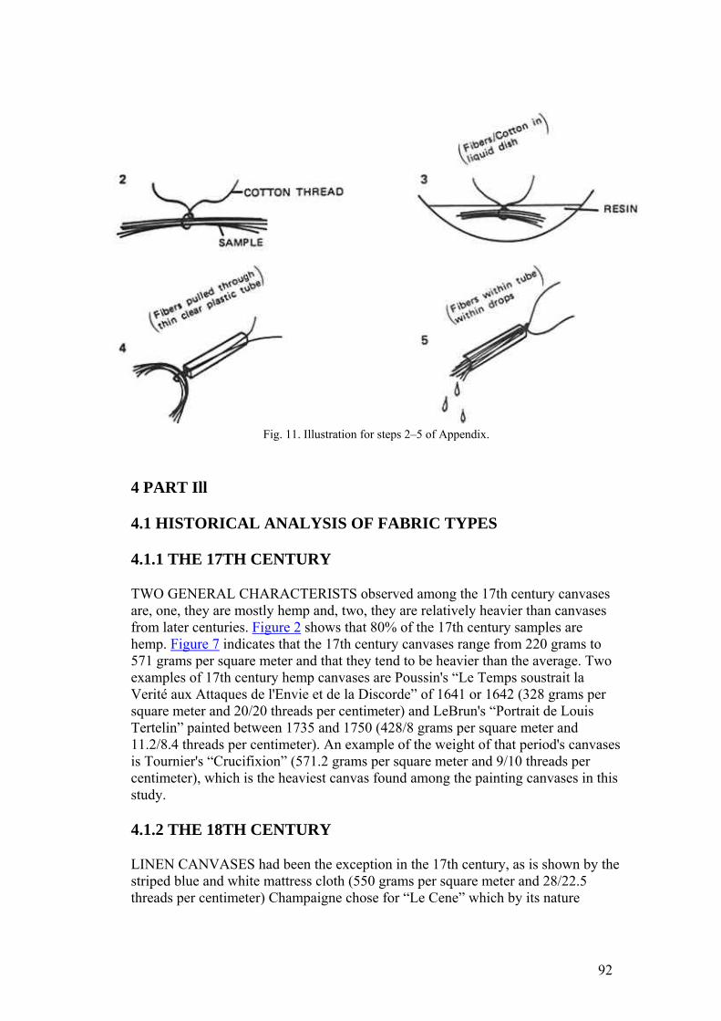
Fig. 11. Illustration for steps 2–5 of Appendix.
4 PART Ill
4.1 HISTORICAL ANALYSIS OF FABRIC TYPES
4.1.1 THE 17TH CENTURY
TWO GENERAL CHARACTERISTS observed among the 17th century canvases are, one, they are mostly hemp and, two, they are relatively heavier than canvases from later centuries. Figure 2 shows that 80% of the 17th century samples are hemp. Figure 7 indicates that the 17th century canvases range from 220 grams to 571 grams per square meter and that they tend to be heavier than the average. Two examples of 17th century hemp canvases are Poussin's “Le Temps soustrait la Verité aux Attaques de l'Envie et de la Discorde” of 1641 or 1642 (328 grams per square meter and 20/20 threads per centimeter) and LeBrun's “Portrait de Louis Tertelin” painted between 1735 and 1750 (428/8 grams per square meter and 11.2/8.4 threads per centimeter). An example of the weight of that period's canvases is Tournier's “Crucifixion” (571.2 grams per square meter and 9/10 threads per centimeter), which is the heaviest canvas found among the painting canvases in this study.
4.1.2 THE 18TH CENTURY
LINEN CANVASES had been the exception in the 17th century, as is shown by the striped blue and white mattress cloth (550 grams per square meter and 28/22.5 threads per centimeter) Champaigne chose for “Le Cene” which by its nature
92
(striped) was clearly not intended for its present use. This fabric too is heavy, weighing more than any other linen canvases (see Fig. 8). In the 18th century as in the 17th century, with only a few exceptions, artists chose very similar canvas types and 85.7% of the 18th century canvases studied are hemp (see Fig. 3). Desportes, Fragonard, C. Halle, N. Halle, and Oudry used hemp canvases, with the exception of Noel Halle's, all weighing from 180 to 280 grams per square meter and all with similar thread counts. Desportes chose the same type of canvases for “Chasse au Renard” of 1719 (13.6/12 threads per cm), for “Gibier, fruits et choux-fleurs” of 1733 (13/13 threads per cm), for “Nature morte à l'Aiguière” of 1734 (12.5/9.5 threads per cm), and for two other paintings with thread counts of 13.3/12.6 and 12/11 threads per cm respectively; Fragonard used a hemp canvas for “L'Inspiration” (15/12 threads per cm) and “La Liseuse” (12/19 threads per cm). Claude Guy Halle selected a hemp canvas for “La Peche” (13.2/12.5 threads per cm) and “Le Saut du Chien” (12.5/11.2 threads per cm); Noel Halle used a hemp cloth for “Dispute de Minerve et Neptune” of 1758 (weighing 430 g per square meter and with 14/11 threads per cm); and Oudry used a hemp fabric for “Instrument de Musique” of 1734 (13/12 threads per cm), “Chasse au Loup” (13.3/13.2 threads per cm), and “Nature Morte, Chien et Gibier Mort” of 1762 (12.6/11.6 threads per cm).
The exceptions to the general type of hemp canvases used in the 18th century can be exemplified by the canvas painting supports chosen by Boucher. Boucher, working in the middle of the 18th century, apparently painted on what was available to him at the time: as Champaigne had done in the 17th century, he used a tightly woven herringbone (24/20 threads per cm) striped blue and white mattress ticking for his “Renaud et Aramide” which he presented at the Academy in 1734; he selected a more loosely woven canvas (17/14 threads per cm) with a hemp warp and a linen weft for “L'Aurore,” and he chose an all hemp canvas for his “Venus chez Vulcain” in 1757 (12.8/10 threads per cm).
4.1.3 THE END OF THE 18TH CENTURY AND THE BEGINNING OF THE 19TH CENTURY
THE TRANSITION from the predominant use of hemp canvase by artists to the virtual disappearance of its use in favor of linen canvases was effected in the late 18th century-early 19th century. Figure 2 shows the gradual switch from hemp to linen during the first quarter of the 19th century, when artists often painted alternatively on hemp and linen supports. Ingres, Hubert Robert, Jean François Hue, Delacroix, Regnault and Troyon represent this transition period well with the variety of their fabric supports. There are three half-linen half-hemp cloths, that is to say fabrics with hemp warp and linen weft. They date from the second half of the 18th century to the 19th century: Boucher's “L'Aurore” (17/14 threads per cm), Vallain's “La Liberté” (14/10 threads per cm), and Boisselier's “Courageuse defense de Louis” of 1827 (14.5/10.5 threads per cm). They too are indications of the gradual change from hemp to linen painting canvases. Of the ten samples taken from pictures by Ingres, four are hemp and six are linen. The Ingres samples cover a wide range of fabric types. The coarsest is the linen canvas used for the “Jupiter et
93
Thetis” (10/6 threads per cm). The finest is the linen canvas used in 1842 for the “Portrait de Cherubini.” In a single year, 1895, Ingres painted the “Portrait de Madame Rivière” in Paris on a hemp cloth (15/15 threads per cm) and the “Portrait de Desmare” on a linen cloth (16/10 threads per cm). While he changes erratically from hemp to linen canvases, the fabrics he uses—whether hemp or linen—consistently tend to become more tightly woven over the course of his career. Ingres' late works are on closely woven linen. Among the three paintings by Hubert Robert analyzed, two were hemp canvases and one a linen canvas. The two J. F. Hue paintings are on a hemp canvas and a striped linen mattress cloth. The six Delacroix samples are evenly divided, showing clearly the switching back and forth from hemp to linen during the transition period. The three hemp canvases are coarser than the three linen ones, however; the most tightly woven hemp sample “Portrait de Riesener” (20/20 threads per cm). In 1830 Delacroix painted “Turc Assis sur un Divan” on a twill weave linen canvas (30/29 threads per cm); three years earlier for a sketch of “Mort de Sardanapale,” he had chosen a poorer quality, loosely woven hemp cloth. Jean Baptiste Regnault painted “Descente de Croix” on a hemp canvas (14/11.5 threads per cm) and his “Education d'Achille” on a patterned satin weave linen cloth (22/19 threads per cm), while Troyon used a very fine linen canvas in 1855 for “Le Retour du Marche” (38/34 threads per cm) and a coarse hemp cloth for “Les Bucherons” (13/12 threads per cm).
4.1.4 THE 19TH CENTURY
AFTER THE TRANSITION period from hemp to linen canvases, 19th century artists painted regularly on machine woven linen, often preprimed (preprimed being used in the sense that the priming was applied to the canvas before it was stretched on its stretcher). Increased industrialization in the 19th century encouraged similarities in canvas types. Corot, Monet, Toulouse-Lautrec, Cezanne, Degas, Manet, Pissarro, Renoir, Carrière, Daubigny, Sisley, and Fantin-Latour all painted on fine linen that is machine woven. There are eleven Corot samples which are all fine linen; the finest is “Jeune Fille à la Mandoline” (31/30 threads per cm) and the coarsest is “Souvenir de Marissel” of 1864 (23.3/16 threads per cm). All of the Corot samples are preprimed.
There are twenty-one linen canvas samples from paintings by Monet. Most are preprimed off-white. The coarsest is “La Gare de Saint-Lazare” painted in 1877 (20/14.5 threads per cm) and the finest is “Madame Monet en Plein Air.” “Le Pont du Chemin de Fer à Argenteuil (23/19 threads per cm) and “Les Coquelicots” (23/20 threads per cm), both painted in 1873, are on nearly identical supports. On the average none of the canvases is either extremely fine and regular nor is any canvas particularly coarse. His canvases become slightly more loosely woven through his early career, from “Nature Morte au Faisan” of 1862 (31/29 threads per cm) to “La Gare de Saint-Lazare” and “La Seine à Argenteuil” of 1877 (25/22 threads per cm).
The three Toulouse-Lautrec canvas samples are preprimed off-white; one is gauze-like linen (14/14 threads per cm), another, “Madame Dieuhl” of 1891, is linen with
94
linen (28/28 threads per cm).
There are six Cezanne samples. One, “Une Moderne Olympia” of 1868, is a gauze-linen (13/12 threads per cm) similar to the one mentioned for Toulouse-Lautrec. One the whole, Cezanne's canvases are not finely woven; they range from the coarsest “Une Moderne Olympia” (13/12 threads per cm) to the finest “Nature Morte à la Soupière” of 1883 (21.5/20 threads per cm). Two of his canvases have nearly identical surface appearances, although the first “Pommes Vertes” (12.6/12.6 threads per cm) is dated 1873 and the other “Pommes et Oranges” (14/11 threads per cm) 1895. Both are preprimed off-white. The priming is worked into the intersticies of the fabric and is visible in the form of small pearls on the back.
All of the six Van Gogh samples are preprimed off-white, and while none are not very tightly woven, none are alike. One, “Le père Tanguy” (12.5/12 threads per cm), resembles the two matching Cezanne samples mentioned above with the off-white priming visible from the reverse. These canvases are all machine woven.
Degas used different weight linen canvases for two paintings created only a year apart: “Portrait de Jeantaud, Linet et Laine” of 1871 (12/11 threads per cm) and “Repetition de Ballet” of 1872 (28/28 threads per cm).
In 1864, Corot, Manet, Pissarro, and Renoir all used fine linen canvases: Corot for “Souvenir de Morte Fontaine” (213/3 g per square meter, 26.6/20.3 threads per cm) and “Souvenir de Marissel” (271.1 g per square meter, 23.3/16 threads per cm), Manet for “Les Fleurs de Pionies” (192 g per square meter, 30/27 threads per cm), Pissarro for “Le Bac à la Varenne St Hilaire” (260 g per square meter, 19/16 threads per cm) and Renoir for “Portrait de Sisley” (32/32 threads per cm).
Most of the Renoir's canvases samples are preprimed off-white or light gray and all are fine linen with the exception of “Jeune Femme rajustant son corsage” painted in 1901 (340 g per square meter, 19/19 threads per cm), which is a bit coarser than the others. In 1876, Renoir used very similar if not the same type of canvas for “Portrait de Madame Daudet” (33/31 threads per cm), “La Balancoire” (32/30 threads per cm) and “Board de Seine à Champrosay” (34/30 threads per cm). “Le Moulin de la Galette” also painted in the same year is on slightly coarser linen (26/25 threads per cm). There is a general tendency for his canvases to become a little less tightly woven over the course of his career.
Pissarro's canvases, on the other hand, appear to become finer: from “Le Bac à la Varenne St Hilaire” of 1864 and “Route de Louvenciennes” of 1870 (488 g per square meter, 15.3/14.6 threads per cm) to 1877 “Les Toits Rouges” (30/25.5 threads per cm).
Of the eleven Sisley samples, ten are linen and one is hemp, “Regate à Henley” (14/13 threads per cm). The finest linen canvas is “Paysage au Petit Printemps” 1886 (36/30 threads per cm). The coarsest is “Les Regates à Moulsey prés de Londres” of 1874 (14.7/14.5 threads per cm).
The Fantin-Latour canvas samples are varied. There is one woven with double threads for both warp and weft, the 1870 “L'Atelier des Batignolles” with gray priming, two with white priming covered with a dark wash, the first “Petite Nature
95
Melon” finer (28.3/27 threads per cm), and finally there is one sample “Fleurs” with light gray priming on fine linen (30/28 threads per cm).
Carriére, Daubigny and Morisot are also among the artists that painted of fine linen, usually with white priming.
The 19th century samples listed above all show the same general characteristic of being machine-woven linen. No further specific traits can be assigned to different shorter periods of time: canvas samples from the 1840's to the 1860's are similar to the canvases from the 1870's to the 1890's. However, certain tendencies can be noted for specific artists.
Towards the very end of the 19th century, cotton fibers start to be employed in making painting canvases. Cotton is first timidly introduced by being woven with linen in order to make a cloth that still retains some of linen's advantages of strength and durability. Then, at the beginning of the 20th century when the price difference between linen and cotton become considerable, all-cotton painting canvases appear. Among the canvases painted towards the end of the 19th century and on into the 20th century, five examples are a combination of cotton and linen. As none of these samples still have their selvage edge, it cannot be said whether the warps are cotton or linen. They are: Vivin's “Reims, la Cathedrale” (preprimed, 13/12.5 threads per cm), Redon's “Hommage à Gauguin” (18.8/15.6 threads per cm), H. Rousseau's “Hommage à la Republique” (preprimed, 14.3/13.3 threads per cm), Peyronnet's “L'Annonce du Garde Champetre” (preprimed, 15/13 threads per cm), and Survage's “Vendeuse de Poisson” (22.5/22 threads per cm).
5 PART IV
5.1 CONCLUSION
THE MAIN CONCLUSION that can be drawn from this study is that French painting canvases are divided into three broad categories: the first, covering the period up to the beginning of the 19th century, when primarily hemp canvases were used; the second situated in the 19th century, when practically only linen fabrics are found; and the last starting at the turn of this century, when cotton and linen share in importance. Only two hundred and twenty-five French painting canvas samples were available for analysis in this paper and, obviously, many more should be added to this nucleus in order to confirm the general trends described above. About one hundred and fifty non-French canvas samples studied still await classification with other samples from the same regions. I hope this article will encourage further documentation on fabric painting supports, as there is a great shortage of knowledge and literature on the subject.
96
ACKNOWLEDGEMENTS
THIS STUDY was made possible through a grant from the Samuel H. Kress Foundation. Mademoiselle MALE, Conservateur en Chef du Service de la Restauration des Peintures des Musées Nationaux, kindly gave me permission to work in her department at the Musée du Louvre and access to their files and their important collection of canvas samples. The Institut Textile de France very generously taught me proper fiber identification techniques and the ways to analyze a fabric.
APPENDIX
1 APPENDIX
THIS IS A simplified explanation on the Gay and Monrocq identification technique used. Please refer to their article for greater detail and the name of the materials used:
1. take a one-inch thread of the fabric to be identified. 2. tie a thin cotton thread to the middle of the sample. 3. dip the sample in a clear plastic mounting medium. 4. thread the cotton through a fine clear flexible vinyl tubing 2 centimeters
long and no more than 2 millimeters in diameter. 5. draw the wet sample with the mounting medium up to the center of the tube. 6. let set. 7. place the tube vertically under a microscope so that the view is on the round
opening—we used a special holder to insert the sample tube vertically under the microscope ready to cut cross sections. This is an instrument called a FIBROTOME designed by the Institut du Textile specifically for fiber cross sections. I imagine a substitute could be invented—the idea is to hold the tube containing the sample vertical so that the view down the microscope is on the opening of the sample tube. The thickness of the section can be controlled by screwing (and unscrewing) the base of the FIBROTOME, which raises and lowers the tube.
8. cut the tube containing the sample with a clean fine razor to make thin discs. 9. pick the sections up and dip them in red dye to tint the different parts of the
fibers. 10. sandwich the sections between a slide and a slide cover with a resin. 11. identify the same. (It takes studying a good number of both hemp and linen
cross sections before you can unhesitatingly label an unknown sample.)
97
JAIC 1991, Volume 30, Number 2, Article 8 (pp. 203 to 213)
THE EFFECTS OF SOLUTION APPLICATION ON SOME MECHANICAL AND PHYSICAL PROPERTIES OF
THERMOPLASTIC AMORPHOUS POLYMERS USED IN CONSERVATION: Poly(vinyl acetate)s
ERIC F. HANSEN, MICHELE R. DERRICK, MICHAEL R. SCHILLING, & RAPHAEL GARCIA
ABSTRACT—The tensile properties of solution-cast poly(vinyl acetate) (PVAC) films are determined by the thermodynamic quality of the solvents. Higher strength and lower elongation are evident in polymer films of poly(vinyl acetate) AYAT (Union Carbide) cast from a solution of acetone or an acetone/ethanol/water mixture, while lower strength and greater elongation are evident in films cast from a solution of chloroform or toluene after drying for 180 days. Films of PVAC-AYAT cast from a toluene solution retained a significant amount (>4%) of solvent, while films cast from the other three solvents retained little solvent (>0.3%). For all polymer films, the glass transition temperature (Tg) was elevated greater than 18°C above the Tg of the bulk polymer. The differences in the tensile properties of the films with little retained solvent is explained on the basis of the thermodynamic quality of the solvents, i.e., the physical properties of the solution-cast polymer film in the dry state may be affected by the conformation of the polymer chain in the solvent. The polymer chain of poly(vinyl acetate) is relatively extended in the “good” solvent chloroform but is more contracted in the “poorer” and more polar solvent, acetone. The effect of solvent quality on the polymer morphology in the dried film was also demonstrated with Fourier transform infrared spectroscopy (FTIR). Changes in spectral band intensity in the FTIR spectra within a series of poly(vinyl acetate)s differing in molecular weights can be discerned when these are deposited on KBr from a chloroform solution but not when deposited from an acetone solution.
1 INTRODUCTION
WHEN SELECTING a thermoplastic polymer for a particular use as a coating, consolidant or adhesive, conservators consider the chemical stability and physical properties of the resin. Some polymers, such as poly(vinyl acetate)s (PVAC) and Acryloid B-72 (Rohm and Haas), have been shown by Feller (1978) to be relatively resistant to environmentally induced chemical modifications. These polymers have been widely used in conservation because they possess a range of physical properties suitable for the treatment of art objects. They have been designated class A materials, which by Feller's definition means that they are expected to remain in a museum environment in excess of 100 years with little comparative change in solubility.
In addition to sufficient “aging” properties, physical properties that accommodate the end use in the conservation of an object are also a concern. For example, if a hard coating is required, Acryloid B-72 is a more suitable choice than the softer
98
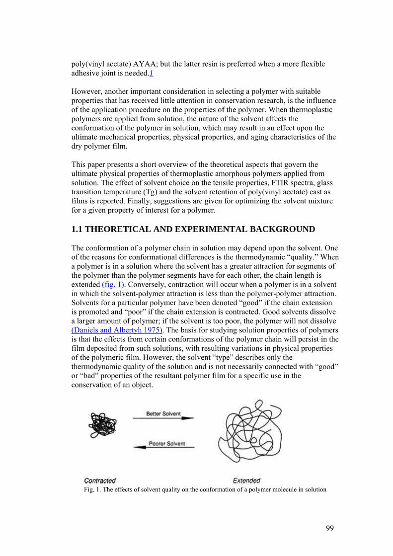
poly(vinyl acetate) AYAA; but the latter resin is preferred when a more flexible adhesive joint is needed.1
However, another important consideration in selecting a polymer with suitable properties that has received little attention in conservation research, is the influence of the application procedure on the properties of the polymer. When thermoplastic polymers are applied from solution, the nature of the solvent affects the conformation of the polymer in solution, which may result in an effect upon the ultimate mechanical properties, physical properties, and aging characteristics of the dry polymer film.
This paper presents a short overview of the theoretical aspects that govern the ultimate physical properties of thermoplastic amorphous polymers applied from solution. The effect of solvent choice on the tensile properties, FTIR spectra, glass transition temperature (Tg) and the solvent retention of poly(vinyl acetate) cast as films is reported. Finally, suggestions are given for optimizing the solvent mixture for a given property of interest for a polymer.
1.1 THEORETICAL AND EXPERIMENTAL BACKGROUND
The conformation of a polymer chain in solution may depend upon the solvent. One of the reasons for conformational differences is the thermodynamic “quality.” When a polymer is in a solution where the solvent has a greater attraction for segments of the polymer than the polymer segments have for each other, the chain length is extended (fig. 1). Conversely, contraction will occur when a polymer is in a solvent in which the solvent-polymer attraction is less than the polymer-polymer attraction. Solvents for a particular polymer have been denoted “good” if the chain extension is promoted and “poor” if the chain extension is contracted. Good solvents dissolve a larger amount of polymer; if the solvent is too poor, the polymer will not dissolve (Daniels and Albertyh 1975). The basis for studying solution properties of polymers is that the effects from certain conformations of the polymer chain will persist in the film deposited from such solutions, with resulting variations in physical properties of the polymeric film. However, the solvent “type” describes only the thermodynamic quality of the solution and is not necessarily connected with “good” or “bad” properties of the resultant polymer film for a specific use in the conservation of an object.
Fig. 1. The effects of solvent quality on the conformation of a polymer molecule in solution
99
Some physical properties of many polymers have been shown to be dependent upon the solvent or solvent mixtures chosen for the solution application. This effect has been demonstrated with ethyl cellulose films on the tensile properties and the permeability to nitrogen and oxygen (Tess 1985) and on the birefringence, brittle-point temperature, and density (Haas et al. 1965). Similarly, for poly(methyl methacrylate) the surface properties of cast films (Schreiber and Croucher 1980), the hardness (Carre et al. 1980), and the shear strength (Briscoe and Smith 1983) have been shown to differ depending upon the solvent used. The time-dependent change (aging) of some mechanical and physical properties is also affected (Kurbanaliyiyev et al. 1982; and Materovsyan et al. 1985).
Olayemi and Adeyeye (1982) tested the tensile properties of PVAC films cast on clean mercury surfaces from solutions of methanol, acetone, and chloroform. They determined some mechanical properties of the films after exposure at 20°C and 65% RH and at 45°C and 65°C in dry ovens. The initial modulus, yield stress, tensile strength, and work-to-rupture were shown to be greater for films cast from a solution of acetone than for those cast from a solution of chloroform. The elongation-to-break showed the reverse trend. Methanol solutions yielded films too brittle for testing. The PVAC films cast from a chloroform solution exhibited the most constant mechanical properties over the longest time interval studied (360 hours). These properties were also dependent upon the temperature of the exposure, decreasing as the temperature increased.
These results were interpreted on the basis of solvent interaction with the polymer molecules both in solution and in the first stage of film formation. (In that stage, the drying rate is controlled by solvent volatility as opposed to solvent diffusion, which controls the second stage of film formation.) The results of the present study confirm those of Olayemi and Adeyeye (1982) and address further considerations: the dependence of the tensile properties of the films on the amount of retained solvent, and whether the physical properties tend toward an equilibrium value after a longer film drying time.
For many polymers used in conservation the choice of solvent deserves careful consideration. In fact, the variation in physical properties of one polymer applied from different solutions may exceed the variation in the physical properties between two different bulk polymers.
The results presented here provide some answers to the following questions:
1. To what extent does solvent retention affect the physical properties of polymers used for conservation purposes? (Retained solvents may plasticize resins with the transitory effects on physical properties disappearing following full solvent release).
2. Over what time period after application will persist the effects on a polymer's physical properties that result from application in a given solvent? If the properties of the polymer reach an equilibrium state relatively quickly
100
after application, regardless of application process, the importance of solvent choice is minimized.
3. Can a solvent be chosen or a solvent composition be manipulated in order to obtain one or more desired properties from a particular resin?
The answer to this last question depends in part upon other factors that affect the final properties of a film. These questions are addressed below in the discussion of film preparation history.
2 EXPERIMENTAL
2.1 MATERIALS
FOUR MOLECULAR weight PVAC resins were used: AYAT (MW = 226,000), AYAF (MW = 169,000), AYAA (MW = 110,000), and AYAC (MW = 14,500). (The molecular weights reported are the weight average molecular weights of PVAC grades as determined by gel permeation chromatography [GPC] [Druzik 1987]). AYAT and AYAF resins were used to cast films from different solvent systems. AYAA, AYAC, and AYAT resin samples were analyzed by FTIR spectroscopy.
Solvents for solution preparation included chloroform, toluene, acetone, and a solution of 10 parts by volume acetone, 10 parts by volume ethanol, and 1 part by volume water.
2.2 FILM PREPARATION
Four percent solutions (w[g]/v[ml]) of AYAT in each of the four solvent systems were cast upon a Teflon FEP (polyhexafluropropylene) surface in break-apart molds as previously described (Hansen and Taketomo 1989). Two series of films with an area of 0.0225 m2 were cast: one series 0.08 mm thick and dried for 50 days and one 0.03 mm thick and dried for 180 days. A constant temperature of 22°C and RH of 65% were maintained throughout the drying intervals.
Additionally, 4% solutions of AYAF in acetone and chloroform were cast in the same manner. Films 0.03 mm thick were dried under the same conditions for 180 days.
2.3 MECHANICAL TESTING
The stress-to-break, strain-to-break, yield-stress, and initial modulus for each drying interval were determined for films of AYAT and AYAF by tensile fracture at constant elongation according to the specifications in ASTM D-2370–82(87), “Standard Test Method of Tensile Properties of Organic Coatings” (ASTM 1989). Values were electronically recorded from an Instron 4201 Universal Testing Instrument and analyzed with the Instron software Series IX Automated Materials Testing System. The temperature and humidity were maintained at 20°C and 65%
101
RH, respectively. Strips 12 mm in width were precision cut using a Thwing Albert JDC Precision Sample Cutter and were fractured at a cross-head speed of 50 mm/min from an initial gauge length of 76 mm. Film thickness over the gauge length varied less than ±5%, determined with an eddy current–type coating thickness gauge which can measure the thickness of a dielectric film (Vector TX1). The tensile values reported for a cast film are the mean of four to nine samples, depending upon the range of the values obtained on the sample sets.
2.4 SOLVENT RETENTION
Films of AYAT were analyzed for residual amounts of solvent. Films at the 50-day drying interval were analyzed for weight percentage of residual solvent at an analytical service center (Baxter Analytical Labs, Irvine, Calif.) by direct insertion probe thermal desorption mass spectrometry using a HP 5987A Mass Spectrometer System. Solvent content was estimated from area ratios of the thermal desorption profile. Direct insertion probe conditions were a temperature ramp from 30°C to 350°C at 15°C/min with a hold at 350°C for 5 minutes.
After drying for 180 days films were analyzed on an HP 5890 Gas Chromatograph (GC) with a CDC 120 pyroprobe. The samples were pyrolyzed at 200°C with the ramp turned off and an interface temperature of 40°C. Optimal separation was obtained on a 25 m Carbowax 20M column with an initial temperature of 100°C ramped to 150°C at 5°C/min. Helium carrier gas was used at a flow rate of 30 ml/min. The FID detector was held at 220°C. Internal standards were used to identify and calibrate the solvent peaks. In addition, reference films were prepared for comparison in which the amount of solvent was determined by a gravimetric method of analysis of films during the drying process. Due to the limited solubility of PVAC AYAT in pure ethanol, this method was not used to determine residual amounts of ethanol.
2.5 THERMAL ANALYSIS
The Tg data of bulk AYAT and AYAF cast from the four solvent systems were obtained by differential scanning calorimetry (DSC). The method used to obtain the Tg has been previously described (Schilling 1989).
2.6 FOURIER TRANSFORM INFRARED SPECTROSCOPY (FTIR)
FTIR spectra were obtained at 4 cm−1 resolution on a DIGILAB 15-E FTIR spectrophotometer equipped with a Motorola 3200 computer and a dry nitrogen purge. A wide-range, cryogenically cooled MCT detector was used to examine the mid-IR region from 4000–500 cm−1. Each spectra was the accumulation of 200 scans.
Sample preparation for the infrared analysis of the bulk resin consisted of dissolving the resins (AYAA, AYAT, AYAC) in chloroform or acetone and
102
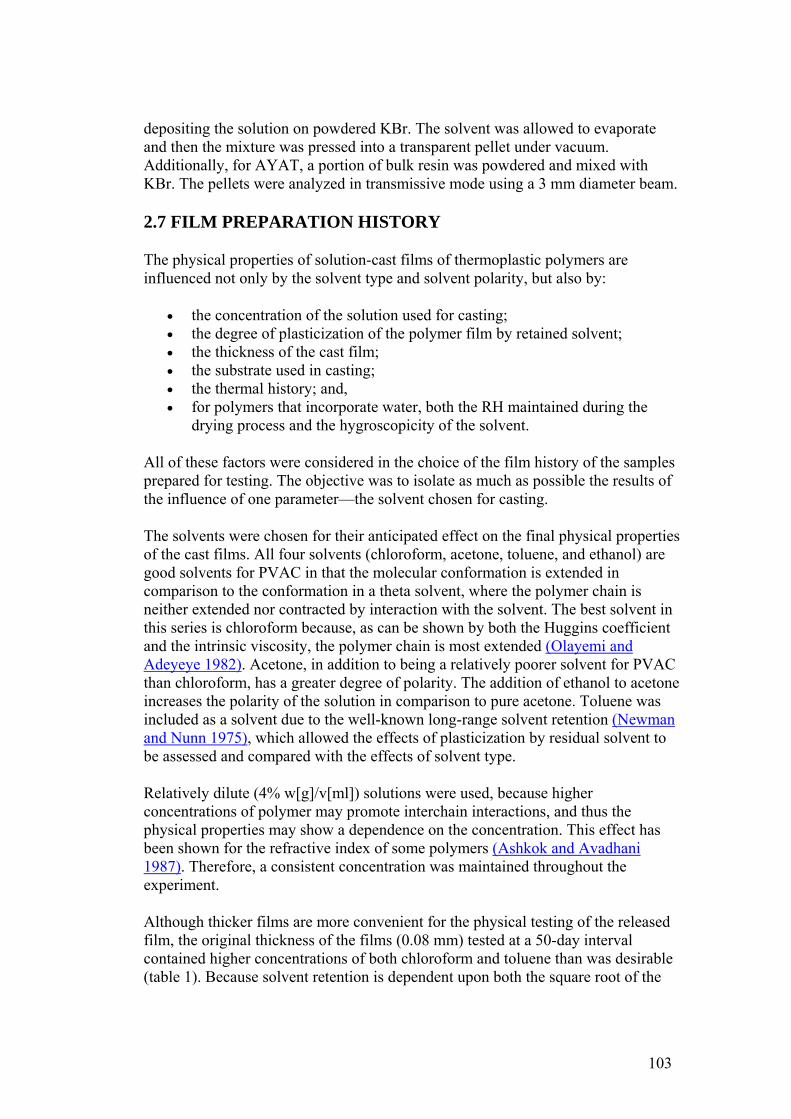
depositing the solution on powdered KBr. The solvent was allowed to evaporate and then the mixture was pressed into a transparent pellet under vacuum. Additionally, for AYAT, a portion of bulk resin was powdered and mixed with KBr. The pellets were analyzed in transmissive mode using a 3 mm diameter beam.
2.7 FILM PREPARATION HISTORY
The physical properties of solution-cast films of thermoplastic polymers are influenced not only by the solvent type and solvent polarity, but also by:
• the concentration of the solution used for casting; • the degree of plasticization of the polymer film by retained solvent; • the thickness of the cast film; • the substrate used in casting; • the thermal history; and, • for polymers that incorporate water, both the RH maintained during the
drying process and the hygroscopicity of the solvent.
All of these factors were considered in the choice of the film history of the samples prepared for testing. The objective was to isolate as much as possible the results of the influence of one parameter—the solvent chosen for casting.
The solvents were chosen for their anticipated effect on the final physical properties of the cast films. All four solvents (chloroform, acetone, toluene, and ethanol) are good solvents for PVAC in that the molecular conformation is extended in comparison to the conformation in a theta solvent, where the polymer chain is neither extended nor contracted by interaction with the solvent. The best solvent in this series is chloroform because, as can be shown by both the Huggins coefficient and the intrinsic viscosity, the polymer chain is most extended (Olayemi and Adeyeye 1982). Acetone, in addition to being a relatively poorer solvent for PVAC than chloroform, has a greater degree of polarity. The addition of ethanol to acetone increases the polarity of the solution in comparison to pure acetone. Toluene was included as a solvent due to the well-known long-range solvent retention (Newman and Nunn 1975), which allowed the effects of plasticization by residual solvent to be assessed and compared with the effects of solvent type.
Relatively dilute (4% w[g]/v[ml]) solutions were used, because higher concentrations of polymer may promote interchain interactions, and thus the physical properties may show a dependence on the concentration. This effect has been shown for the refractive index of some polymers (Ashkok and Avadhani 1987). Therefore, a consistent concentration was maintained throughout the experiment.
Although thicker films are more convenient for the physical testing of the released film, the original thickness of the films (0.08 mm) tested at a 50-day interval contained higher concentrations of both chloroform and toluene than was desirable (table 1). Because solvent retention is dependent upon both the square root of the
103
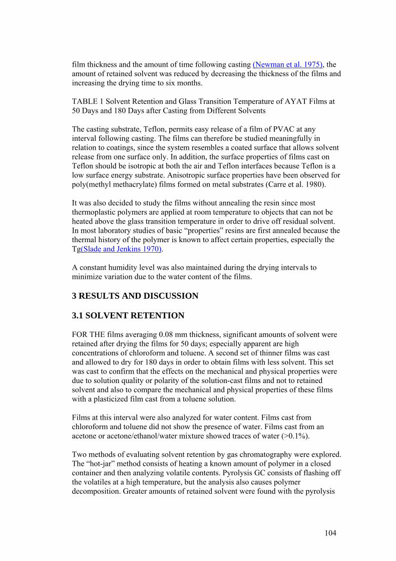
film thickness and the amount of time following casting (Newman et al. 1975), the amount of retained solvent was reduced by decreasing the thickness of the films and increasing the drying time to six months.
TABLE 1 Solvent Retention and Glass Transition Temperature of AYAT Films at 50 Days and 180 Days after Casting from Different Solvents
The casting substrate, Teflon, permits easy release of a film of PVAC at any interval following casting. The films can therefore be studied meaningfully in relation to coatings, since the system resembles a coated surface that allows solvent release from one surface only. In addition, the surface properties of films cast on Teflon should be isotropic at both the air and Teflon interfaces because Teflon is a low surface energy substrate. Anisotropic surface properties have been observed for poly(methyl methacrylate) films formed on metal substrates (Carre et al. 1980).
It was also decided to study the films without annealing the resin since most thermoplastic polymers are applied at room temperature to objects that can not be heated above the glass transition temperature in order to drive off residual solvent. In most laboratory studies of basic “properties” resins are first annealed because the thermal history of the polymer is known to affect certain properties, especially the Tg(Slade and Jenkins 1970).
A constant humidity level was also maintained during the drying intervals to minimize variation due to the water content of the films.
3 RESULTS AND DISCUSSION
3.1 SOLVENT RETENTION
FOR THE films averaging 0.08 mm thickness, significant amounts of solvent were retained after drying the films for 50 days; especially apparent are high concentrations of chloroform and toluene. A second set of thinner films was cast and allowed to dry for 180 days in order to obtain films with less solvent. This set was cast to confirm that the effects on the mechanical and physical properties were due to solution quality or polarity of the solution-cast films and not to retained solvent and also to compare the mechanical and physical properties of these films with a plasticized film cast from a toluene solution.
Films at this interval were also analyzed for water content. Films cast from chloroform and toluene did not show the presence of water. Films cast from an acetone or acetone/ethanol/water mixture showed traces of water (>0.1%).
Two methods of evaluating solvent retention by gas chromatography were explored. The “hot-jar” method consists of heating a known amount of polymer in a closed container and then analyzing volatile contents. Pyrolysis GC consists of flashing off the volatiles at a high temperature, but the analysis also causes polymer decomposition. Greater amounts of retained solvent were found with the pyrolysis
104

method, evidently because heating in a closed container did not fully volatize all retained solvent. Therefore, the amounts reported in table 1 are those obtained by pyrolysis GC.
Concentrations of acetone and chloroform were below the detection limits for films cast from these solvents at a 180-day interval. However, films cast from toluene retained 4% by weight of solvent.
3.2 TENSILE PROPERTIES
The tensile properties of AYAT films cast from different solvents (tables 2, 3, and 4) are highly dependent upon both the solvent used for casting and the time interval after casting.
TABLE 2a Yield-Stress and Stress-at-Break of AYAT Films at 50 Days after Casting from Different Solvents
TABLE 2b Yield-Stress and Stress-at-Break of AYAT Films at 180 Days after Casting from Different Solvents
TABLE 3 Initial Elastic Modulus of AYAT Films at 50 and 180 Days after Casting from Different Solvents
TABLE 4 Percent Strain-to-Break of AYAT Films at 50 and 180 Days after Casting from Different Solvents
Representative stress-strain curves obtained from tensile fracture at a constant rate of elongation are shown in figures 2 and 3 for samples of films dried for 50 days and 180 days, respectively. The yield-stress differs from the stress-at-break for samples with a yield point, beyond which further elongation occurs with plastic flow. After drying for 50 days, only samples from films cast from the more polar acetone/ethanol mixture have a sharp break point, exhibiting no plastic flow at this elongation rate. After drying for 180 days, samples from films cast from both acetone and an acetone/ethanol mixture fracture with the peak applied stress at 3% elongation. Samples from films cast from both chloroform and toluene continue to flow to above a 200% strain-to-break after the yield point.
105
Fig. 2. Representative tensile properties at 50 days of AYAT films cast from different solvents
Fig. 3. Representative tensile properties at 180 days of AYAT films cast from different solvents
The initial elastic modulus increases with both drying time and solvent polarity. Again, two groups are apparent: one of higher modulus for films cast from acetone or acetone/ethanol solutions and a second of lower modulus for films cast from solutions of either chloroform or toluene.
106
The differences in tensile properties of the films can be related to the amount of retained solvent after 50 days of drying (see table 1). However, the data from the GC analysis for the 180-day interval confirms that the differences in the tensile properties of some films are related to solvent type and solvent retention (table 3). Only trace amounts of chloroform or acetone are still present in the films, but the tensile properties are distinctly different. When the better solvent, chloroform, is used in casting, the strain-to-break of the samples exceeds 200% compared to 3% for the acetone mixtures. With respect to films cast from toluene, the amount of retained solvent may still be important in plasticizing the films, with a resultant lower stress-to-break and greater strain-to-break compared to films cast from an acetone solution.
With time, changes in the properties of a cast resin are related not only to solvent release but also to the physical aging of the polymer. Amorphous polymeric materials move toward an increased state of brittleness with increasing time when maintained at a temperature below their Tg. In this case, performance with time should be evaluated with the understanding that increased brittleness will occur from physical aging (Struik 1978). This is a result of a thermodynamic drive toward a physical equilibrium state, in addition to the more well-known and addressed effect of chemical modifications (oxidation, hydrolysis, chain-breaking) that may also cause a more brittle state of a polymer.
Several problems exist when attempting to maximize a specific physical property of a cast resin by adjustments to the polymer/solvent mixture used for casting. Use of a different solvent may result in a different submicroporosity that affects the density and permeability of a cast film (Malkin 1983). Also, solvent mixtures are not explicitly additive in their effect on the polymer conformation due to polar interactions between the solvent and polymer.
Malkin (1983) has shown that the thermodynamic quality of the solution, as indicated by the intrinsic viscosity, cannot be used to predict a property of the resin cast from it. Instead, there are peaks in the curves for plots of intrinsic viscosity versus a mechanical property for acrylics and cellulose ethers. The tensile properties of ethyl cellulose do not correlate with solvent polarity but maximize at a 30% ethanol/toluene mixture (Tess 1985). For this polymer there is a simultaneous increase in elongation and strength, in contrast to poly(vinyl acetate) where the strength and elongation show inverse relations when changing solution quality and polarity. These results suggest that the exact effect of the solution quality and polarity on the mechanical properties of a polymer must be experimentally determined.
3.3 THERMAL ANALYSIS
The initial reason for using thermoanalytic techniques was to determine if the level of solvent was sufficient to cause plasticization of the films. Plasticizers are materials incorporated into other materials to increase flexibility, distension, or workability. Plasticizers, either intentionally incorporated or a result of retained
107
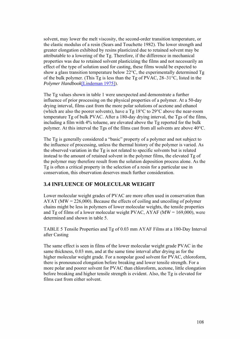
solvent, may lower the melt viscosity, the second-order transition temperature, or the elastic modulus of a resin (Sears and Touchette 1982). The lower strength and greater elongation exhibited by resins plasticized due to retained solvent may be attributable to a lowering of the Tg. Therefore, if the difference in mechanical properties was due to retained solvent plasticizing the films and not necessarily an effect of the type of solution used for casting, these films would be expected to show a glass transition temperature below 22°C, the experimentally determined Tg of the bulk polymer. (This Tg is less than the Tg of PVAC, 28–31°C, listed in the Polymer Handbook[Lindeman 1975]).
The Tg values shown in table 1 were unexpected and demonstrate a further influence of prior processing on the physical properties of a polymer. At a 50-day drying interval, films cast from the more polar solutions of acetone and ethanol (which are also the poorer solvents), have a Tg 18°C to 29°C above the near-room temperature Tg of bulk PVAC. After a 180-day drying interval, the Tgs of the films, including a film with 4% toluene, are elevated above the Tg reported for the bulk polymer. At this interval the Tgs of the films cast from all solvents are above 40°C.
The Tg is generally considered a “basic” property of a polymer and not subject to the influence of processing, unless the thermal history of the polymer is varied. As the observed variation in the Tg is not related to specific solvents but is related instead to the amount of retained solvent in the polymer films, the elevated Tg of the polymer may therefore result from the solution deposition process alone. As the Tg is often a critical property in the selection of a resin for a particular use in conservation, this observation deserves much further consideration.
3.4 INFLUENCE OF MOLECULAR WEIGHT
Lower molecular weight grades of PVAC are more often used in conservation than AYAT (MW = 226,000). Because the effects of coiling and uncoiling of polymer chains might be less in polymers of lower molecular weights, the tensile properties and Tg of films of a lower molecular weight PVAC, AYAF (MW = 169,000), were determined and shown in table 5.
TABLE 5 Tensile Properties and Tg of 0.03 mm AYAF Films at a 180-Day Interval after Casting
The same effect is seen in films of the lower molecular weight grade PVAC in the same thickness, 0.03 mm, and at the same time interval after drying as for the higher molecular weight grade. For a nonpolar good solvent for PVAC, chloroform, there is pronounced elongation before breaking and lower tensile strength. For a more polar and poorer solvent for PVAC than chloroform, acetone, little elongation before breaking and higher tensile strength is evident. Also, the Tg is elevated for films cast from either solvent.
108
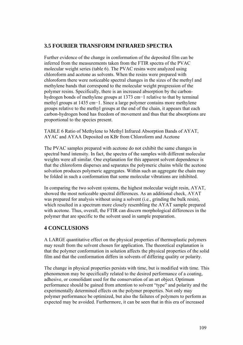
3.5 FOURIER TRANSFORM INFRARED SPECTRA
Further evidence of the change in conformation of the deposited film can be inferred from the measurements taken from the FTIR spectra of the PVAC molecular weight series (table 6). The PVAC resins were analyzed using chloroform and acetone as solvents. When the resins were prepared with chloroform there were noticeable spectral changes in the sizes of the methyl and methylene bands that correspond to the molecular weight progression of the polymer resins. Specifically, there is an increased absorption by the carbon-hydrogen bonds of methylene groups at 1373 cm−1 relative to that by terminal methyl groups at 1435 cm−1. Since a large polymer contains more methylene groups relative to the methyl groups at the end of the chain, it appears that each carbon-hydrogen bond has freedom of movement and thus that the absorptions are proportional to the species present.
TABLE 6 Ratio of Methylene to Methyl Infrared Absorption Bands of AYAT, AYAC and AYAA Deposited on KBr from Chloroform and Acetone
The PVAC samples prepared with acetone do not exhibit the same changes in spectral band intensity. In fact, the spectra of the samples with different molecular weights were all similar. One explanation for this apparent solvent dependence is that the chloroform disperses and separates the polymeric chains while the acetone solvation produces polymeric aggregates. Within such an aggregate the chain may be folded in such a conformation that some molecular vibrations are inhibited.
In comparing the two solvent systems, the highest molecular weight resin, AYAT, showed the most noticeable spectral differences. As an additional check, AYAT was prepared for analysis without using a solvent (i.e., grinding the bulk resin), which resulted in a spectrum more closely resembling the AYAT sample prepared with acetone. Thus, overall, the FTIR can discern morphological differences in the polymer that are specific to the solvent used in sample preparation.
4 CONCLUSIONS
A LARGE quantitative effect on the physical properties of thermoplastic polymers may result from the solvent chosen for application. The theoretical explanation is that the polymer conformation in solution affects the physical properties of the solid film and that the conformation differs in solvents of differing quality or polarity.
The change in physical properties persists with time, but is modified with time. This phenomenon may be specifically related to the desired performance of a coating, adhesive, or consolidant used for the conservation of an art object. Optimum performance should be gained from attention to solvent “type” and polarity and the experimentally determined effects on the polymer properties. Not only may polymer performance be optimized, but also the failures of polymers to perform as expected may be avoided. Furthermore, it can be seen that in this era of increased
109
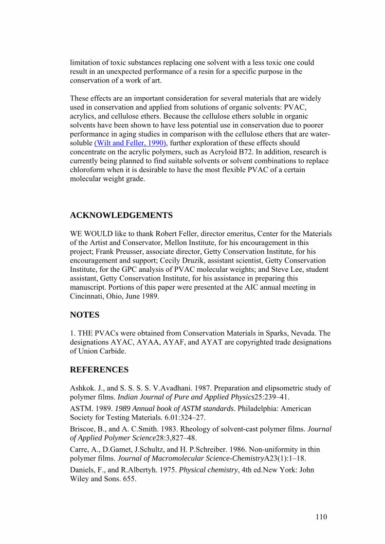
limitation of toxic substances replacing one solvent with a less toxic one could result in an unexpected performance of a resin for a specific purpose in the conservation of a work of art.
These effects are an important consideration for several materials that are widely used in conservation and applied from solutions of organic solvents: PVAC, acrylics, and cellulose ethers. Because the cellulose ethers soluble in organic solvents have been shown to have less potential use in conservation due to poorer performance in aging studies in comparison with the cellulose ethers that are water-soluble (Wilt and Feller, 1990), further exploration of these effects should concentrate on the acrylic polymers, such as Acryloid B72. In addition, research is currently being planned to find suitable solvents or solvent combinations to replace chloroform when it is desirable to have the most flexible PVAC of a certain molecular weight grade.
ACKNOWLEDGEMENTS
WE WOULD like to thank Robert Feller, director emeritus, Center for the Materials of the Artist and Conservator, Mellon Institute, for his encouragement in this project; Frank Preusser, associate director, Getty Conservation Institute, for his encouragement and support; Cecily Druzik, assistant scientist, Getty Conservation Institute, for the GPC analysis of PVAC molecular weights; and Steve Lee, student assistant, Getty Conservation Institute, for his assistance in preparing this manuscript. Portions of this paper were presented at the AIC annual meeting in Cincinnati, Ohio, June 1989.
NOTES
1. THE PVACs were obtained from Conservation Materials in Sparks, Nevada. The designations AYAC, AYAA, AYAF, and AYAT are copyrighted trade designations of Union Carbide.
REFERENCES
Ashkok. J., and S. S. S. S. V.Avadhani. 1987. Preparation and elipsometric study of polymer films. Indian Journal of Pure and Applied Physics25:239–41. ASTM. 1989. 1989 Annual book of ASTM standards. Philadelphia: American Society for Testing Materials. 6.01:324–27. Briscoe, B., and A. C.Smith. 1983. Rheology of solvent-cast polymer films. Journal of Applied Polymer Science28:3,827–48. Carre, A., D.Gamet, J.Schultz, and H. P.Schreiber. 1986. Non-uniformity in thin polymer films. Journal of Macromolecular Science-ChemistryA23(1):1–18. Daniels, F., and R.Albertyh. 1975. Physical chemistry, 4th ed.New York: John Wiley and Sons. 655.
110
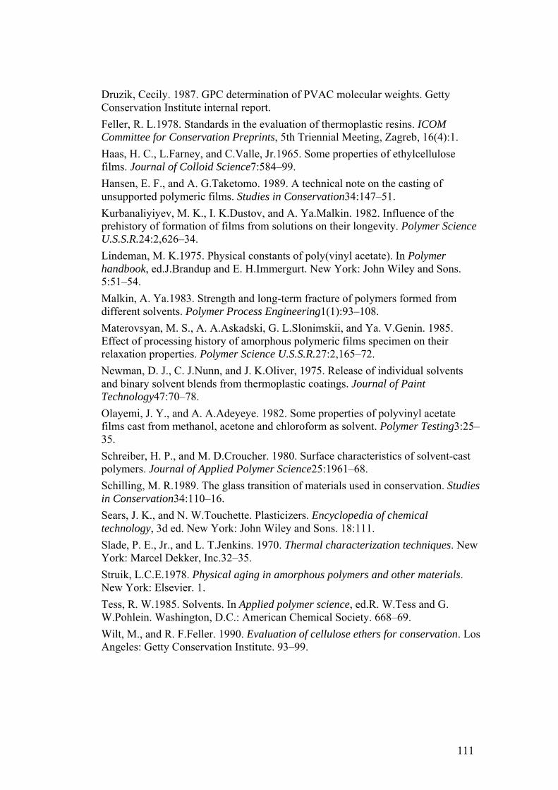
Druzik, Cecily. 1987. GPC determination of PVAC molecular weights. Getty Conservation Institute internal report. Feller, R. L.1978. Standards in the evaluation of thermoplastic resins. ICOM Committee for Conservation Preprints, 5th Triennial Meeting, Zagreb, 16(4):1. Haas, H. C., L.Farney, and C.Valle, Jr.1965. Some properties of ethylcellulose films. Journal of Colloid Science7:584–99. Hansen, E. F., and A. G.Taketomo. 1989. A technical note on the casting of unsupported polymeric films. Studies in Conservation34:147–51. Kurbanaliyiyev, M. K., I. K.Dustov, and A. Ya.Malkin. 1982. Influence of the prehistory of formation of films from solutions on their longevity. Polymer Science U.S.S.R.24:2,626–34. Lindeman, M. K.1975. Physical constants of poly(vinyl acetate). In Polymer handbook, ed.J.Brandup and E. H.Immergurt. New York: John Wiley and Sons. 5:51–54. Malkin, A. Ya.1983. Strength and long-term fracture of polymers formed from different solvents. Polymer Process Engineering1(1):93–108. Materovsyan, M. S., A. A.Askadski, G. L.Slonimskii, and Ya. V.Genin. 1985. Effect of processing history of amorphous polymeric films specimen on their relaxation properties. Polymer Science U.S.S.R.27:2,165–72. Newman, D. J., C. J.Nunn, and J. K.Oliver, 1975. Release of individual solvents and binary solvent blends from thermoplastic coatings. Journal of Paint Technology47:70–78. Olayemi, J. Y., and A. A.Adeyeye. 1982. Some properties of polyvinyl acetate films cast from methanol, acetone and chloroform as solvent. Polymer Testing3:25–35. Schreiber, H. P., and M. D.Croucher. 1980. Surface characteristics of solvent-cast polymers. Journal of Applied Polymer Science25:1961–68. Schilling, M. R.1989. The glass transition of materials used in conservation. Studies in Conservation34:110–16. Sears, J. K., and N. W.Touchette. Plasticizers. Encyclopedia of chemical technology, 3d ed. New York: John Wiley and Sons. 18:111. Slade, P. E., Jr., and L. T.Jenkins. 1970. Thermal characterization techniques. New York: Marcel Dekker, Inc.32–35. Struik, L.C.E.1978. Physical aging in amorphous polymers and other materials. New York: Elsevier. 1. Tess, R. W.1985. Solvents. In Applied polymer science, ed.R. W.Tess and G. W.Pohlein. Washington, D.C.: American Chemical Society. 668–69. Wilt, M., and R. F.Feller. 1990. Evaluation of cellulose ethers for conservation. Los Angeles: Getty Conservation Institute. 93–99.
111
AUTHOR INFORMATION
ERIC F. HANSEN graduated from the University of California at Irvine in 1980 with an M.S. in organic chemistry and joined the Getty Conservation Institute in 1985. In his current position as an associate scientist he is pursuing his interests in the environmentally induced deterioration of synthetic and natural organic materials (including collagen, fibroin, and keratin), the conservation of ethnographic and archaeological objects, and the analysis of the effects of treatment parameters on the final physical and optical properties of treated objects. Address: Getty Conservation Institute, 4503 Glencoe Ave., Marina del Rey, Calif. 90292.
MICHELE R. DERRICK graduated from Oklahoma State University in 1979 with an M.S. in analytical chemistry. She joined the Getty Conservation Institute in 1983 and is currently an associate scientist. Her research involves the development of new methods for the characterization and identification of organic materials in cultural objects primarily using infrared spectroscopy and pyrolysis gas chromatography. Address: Getty Conservation Institute, 4503 Glencoe Ave., Marina del Rey, Calif. 90292.
MICHAEL R. SCHILLING graduated from California State Polytechnic University at Pomona in 1990 with an M.S. in chemistry. He joined the Getty Conservation Institute in 1983 and is currently an associate scientist. He specializes in thermal analysis research, the examination of painted surfaces, and instrumental analysis (gas chromatography-mass spectroscopy). Address: Getty Conservation Institute, 4503 Glencoe Ave., Marina del Rey, Caif. 90292.
RAFAEL GARCIA worked at the Getty Conservation Institute as a student assistant from 1987 to 1989 while pursuing undergraduate studies in chemistry at Loyola Marymount University. He received his B.S. in 1989 and is currently a graduate student in chemistry at California State University at Long Beach. Address: Getty Conservation Institute, 4503 Glencoe Ave., Marina del Rey, Calif. 90202.
112
JAIC 1987, Volume 26, Number 1, Article 5 (pp. 59 to 63)
SOME USES OF A VIDEO CASSETTE RECORDER IN THE CONSERVATION LABORATORY
Alexander Katlan, Barbara Appelbaum, & Paul Himmelstein
ABSTRACT—Several uses for a video cassette recorder are presented: in conservation surveys (using a video camera), in conjunction with an infrared vidicon camera, and in the detailed documentation of the surface condition of large works of art.
THIS SHORT ARTICLE contains several informal notes on the use of a video cassette recorder in two conservation practices. Unlike many other “high-tech” tools used in the field of conservation, the video recorder is a household appliance designed for the technically unsophisticated. Because of this, technical issues like the accuracy of color rendition or high resolution of the image, usually of primary importance in conservation work, are not a major consideration. Video tape does not in any way replace traditional photographic work in the conservation laboratory, but provides a method of recording and storing large amounts of information quickly and easily. We are reporting on our experiences in the hope that it will encourage other conservators to investigate further uses of the VCR in the conservation lab and in museums.
1 THE USE OF THE VCR IN CONSERVATION AND OTHER COLLECTION SURVEYS
TWO OF US (Appelbaum and Himmelstein) about two years ago purchased a video cassette recorder and video camera for use in conservation surveys. The choice of equipment was made primarily on the basis of cost and ease of use, although we specified that we wanted to be able to use the camera in low light levels, and we wanted a macro lens. The equipment was very helpful.1 With no additional lighting in dimly-lit storage rooms and exhibition galleries, we could quickly record all the pieces surveyed, with as many views as we wanted, and with details of areas of damage using the built-in zoom lens. For pieces like large or complex sculptures, the use of the VCR provides more information than almost any number of still photographs. Our informal comments, keyed to the needs of the survey, were also recorded on the tape, along with any identifying information. When helpful, we referred to a list we had previously prepared containing the categories of information we wished to note. This is sometimes important, as in many surveys it is impossible to go back to pieces seen previously to record missing information. The video tape allowed us to record a great deal of information and store it in a compact way.
Our basic procedure in doing surveys on tape is to examine each object first and discuss our findings. When we are ready to record, one of us holds the object, moving it as necessary for the picture. This person reads the accession number and condition notes aloud onto the tape, and points out areas that
113
would benefit from close-ups. When relevant, we include the reverse of paintings, the inside of vessels, problems caused by mounts, etc. For pieces where only one still photograph is required, the tape is run only for the length of time it takes to record our commentary. The second person holds the camera and reads numbers from the footage counter in the camera so that they can be written onto our list of objects. Our copy of the final survey report includes the index numbers so that the images can be retrieved easily. For our own use, we also keep written notes of condition on lists provided by museum staff. If a survey were to be done with only one conservator, a quick-witted museum staff member would be drafted for help in handling the objects.
When writing the survey reports in our own laboratory, we compile a list of objects with basic notes on condition and proposed treatments from our written notes, and then refer to the tape for further details. The use of our computer, a Macintosh, in writing these reports is vital, since the outlines of reports can be typed, and then details added as the tape is viewed or as decisions are made about treatment recommendations and costs. As with audio tape, writing a lengthy report without written notes is quite awkward and time-consuming, and would be particularly difficult without a word processor.
The tapes have proved useful long after the survey report was written, in refreshing our memories about pieces that we were preparing to treat, and on changes in condition that might have occurred between the time of the survey and the time we were asked to treat a piece. In one case, the tapes also became a possible source of comparison in a collection where insect infestation was suspected. We expect at this time to be able to specify which pieces have more flight holes since the survey was completed.
One of the main advantages of video tape is that the images are instantly available, without the time and expense of film development, choosing negatives, making prints, identifying the objects, labelling the prints, and storing them in a way that permits easy retrieval. For the same purposes, the only bookkeeping needed for video tape is a written list of the objects recorded on each cassette, and, if necessary, the index numbers noted on reports. A small cassette holds information on a large number of objects. With at least two hours of tape on a cassette and a minimum of a few seconds' scan for each object, several hundred pieces can be recorded on one tape. Although for condition and treatment photographs, and for permanence of the image, video tape is no substitute for photographic prints, for many other purposes it is a very efficient tool.
Another use of a video tape scan is to record details of the surface of large paintings. One eight-by-ten inch photograph of a large painting makes details unreadable. Taking same-scale photographs over the whole surface in order to construct a mosaic is very difficult. Scanning with the video camera is very easy. For paintings, particularly abstract ones, which are travelling, the video tape scan allows comparison with either the actual painting or with
114
photographs of possible damage in transit. The tape helps to answer the frequent, and aggravating, question: “Was that there before?”
Other potential uses of the video camera include instant comparison of a piece or a small area of a piece before and immediately after certain treatment procedures. For example, it is sometimes helpful when filling losses in paintings or objects to have an image of the unfilled area for comparison. For outdoor sculpture or building surveys, video tape would be extremely useful. The use of video tape in educating conservators by recording treatment techniques, educating trustees about museum problems, or educating museum staff about conservation concerns could also make it a powerful propaganda tool.
In addition, it is becoming more clear that many museums lack photographic records of their collections. Although prints of individual pieces are certainly the preferred medium, video tape records can be made in very small amounts of time, with less hazard to the collections from being moved to photographic studios, heat from lights, and handling. We are currently recommending to our institutional clients that they consider creating a video tape record of their collections. For purposes of evidence in case of theft or damage, for use by curators in-house, potential borrowers, or visitor/browsers, such a tape would be extremely valuable.
We recently experimented with the use of VCR in conjunction with transmitted and reflected infrared scanning of a number of paintings.2 The results were quite successful and the process was greatly simplified over still photography.
2 THE USE OF THE VCR AS A METHOD OF RECORDING INFRARED IMAGES
THE TRADITIONAL METHOD of recording information from an infrared vidicon unit is to photograph with a conventional film camera directly from the television monitor. This method has the advantage of producing black-and-white prints and negatives. One disadvantage is a loss of focus around the edges of the photograph because of geometric distortion due to the curvature of the screen; a number of institutions have purchased a monitor with a flat screen to compensate for this problem. In addition, the recorded image is not immediately available.
Overall scanning, from edge to edge, of a painting has to be done frame by frame and results in the construction of a photographic mosaic. The process of making a photo-mosaic has its own problems: difficulty in matching the image at the edges of the prints, and differences in density of the prints. The difference in density is partially caused by the IR camera which automatically adjusts the image as it moves from light to dark. The result is that the mosaic,
115
which is extremely time-consuming to construct, is difficult to read.
In using a video cassette recorder for recording infrared images, the output of the infrared camera is hooked directly into the video recorder. A painting was examined first by infrared, and decisions were made about exactly what to record. The actual process of recording went very quickly; the examination and recording of infrared images of about a dozen paintings were made within one afternoon. With experience, the whole process could go much faster.
3 EQUIPMENT
THE VIDEO RECORDER we use is a Quasar VP5435wQ VCR. The camera is a Panasonic WV-3230/8AF with auto-focus, zoom and macro lens. The video tape records in color, although the playback through the camera monitor is black-and-white. The final color rendering is not perfect by any means; it would be possible to improve this by re-balancing the color more frequently during use, and by increasing the light levels. Our VCR contains a rechargeable battery pack, and can record six hours of tape without an outside power source, so that surveys can be done outdoors, or in other areas without the need of plugging into an electric outlet. No special lights or lenses were used; the equipment was used in exactly the same way as it would be by a home hobbyist. Most such recorders have similar features, like “freeze-frame” capability, date and time that can be recorded on the image, automatic focus, a zoom lens, etc. We would not necessarily recommend our equipment over any other, although we are completely satisfied with it. New equipment, smaller and lighter, comes out every year, and ease of use is a primary consideration.
The infrared equipment used was a Dage MTI 65 MK2 video camera, with a Schott infrared filter #RG850 with a 50 mm. Canon macro lens. The infrared tube was made by Hamamatsu, model no. N214-01, and the monitor was an Audiotronics model, with 800 lines horizontal resolution. A quick trip to an electronics store provided the necessary adapters for the hook-up. The VCR is hooked up directly to the output of the Vidicon system, and the image appears on the monitor as usual. When the VCR is activated, the image that appears on the screen is recorded on video tape as well.
4 ADVANTAGES OF THE VCR
1. Large numbers of images can be recorded easily, with no need to move objects to a photographic studio. The pieces can be moved during recording, so that the total amount of information recorded is much greater than with any number of still photographs.
2. The ease of operation and speed of recording allows a great deal of information to be recorded without interruption of the survey process. For use with infrared, the speed of recording makes it possible to record as a routine every painting that is scanned, including those which appear to have nothing of interest. There is no need to interpret
116
images before deciding what to photograph. When paintings by a particular artist are being studied, even the absence of underdrawing on IR can be a useful piece of information.
3. A voice recording can be recorded simultaneously with the recording of the image to identify the object and to explain what is being shown.
4. A library of visible light and infrared images, similar to the libraries of x-radiographs that many museums have, can be easily built up. A great deal of information can be stored on one cassette, particularly compared to the space required to store corresponding numbers of photographic negatives and prints.
5. A whole tape can be duplicated commercially, or with two tape machines.
6. It is easy to compare a “freeze-frame” image on the monitor with a photographic print.
7. It is a simple matter to include on the same tape an image of the artifact under normal illumination, or under raking light. For some legal purposes, it may be important to include a photograph of the painting being turned around to read the inscription. A single still photographic print may provide a reading of an inscription, but does not in itself indicate what painting it came from.
5 DISADVANTAGES
1. The main disadvantage is that no hard copy is produced. However, at worst, the conservator has almost exactly what he would have had before, that is, an image on a monitor screen. Images can be chosen and photographed at any time, with only slight loss of quality. When necessary, as for inscriptions, photographs can be taken for a client. For purposes of research, we feel that it is more important in most cases that the private conservator or the museum laboratory retain a permanent record than that the client or curator have infrared photographs. Because of the rapid developments in technology, the direct production of highquality still prints from a video tape will undoubtedly soon become possible.3
2. Viewing requires a video tape player and a monitor. This is getting to be less of a problem, since many museums already use video tape in their education departments and therefore have monitors, and many people own tape players. (Extensive use of video tape in the conservation laboratory may make the purchase of a monitor, i.e. television, advisable. This may lure curators into the laboratory during important events, like the final game of the World Series. It is not clear at this time whether this should be seen as an advantage or disadvantage.)
3. During the infrared scanning process, the VCR records the slight vibration and temporarily out-of-focus image produced while the camera is moving. This can be eliminated by turning the VCR on and off, or by stopping the camera periodically to record a still image.
117
4. The resolution of the video tape image is never more than and usually less than that produced by the camera.
5. Questions have arisen about the permanence of video tape. For our purposes, this is not a problem. For museums or laboratories interested in using electronic recording media for long-term records, hard disks appear to be preferable.
6. Comparison between infrared images on video tape would require duplicate tapes and two monitors.
The video cassette recorder may be a complex piece of electronics, but it is, after all, a non-scientific household appliance. The ease of use makes it applicable for many purposes where traditional photographic methods are too time-consuming or too difficult. We would like to encourage conservators to experiment and report on other uses.
REFERENCES
BarbaraAppelbaum, PaulHimmelstein, “Planning for a Conservation Survey,” Museum News64, no. 3, (Feb. 1986), pp. 5–14
This use has been suggested previously: William A. Real, “Infrared reflectography at the Cleveland Museum of Art: Paintings, Objects, Manuscripts,”AIC Preprints, Washington, D.C., 1985, pp. 79–89, and personal communication with Donald K. Beman, Associate Director, Beman Galleries, Nyack, New York.
Computer programs for microcomputers which produce digitized images from video sources, allowing a print to be made on a printer, are now available. At present there is considerable loss of quality, but this will no doubt improve.
118
JAIC 2003, Volume 42, Number 2, Article 9 (pp. 341 to 362)
BEVA 371 AND ITS USE AS AN ADHESIVE FOR SKIN AND LEATHER REPAIRS: BACKGROUND AND A REVIEW OF
TREATMENTS
LISA KRONTHAL, JUDITH LEVINSON, CAROLE DIGNARD, ESTHER CHAO, & JANE DOWN
ABSTRACT—Since its introduction in the 1970s, the use of BEVA 371 (solution and film) has expanded from the field of paintings conservation into textiles and objects conservation. During the development of BEVA 371 solution, initial testing was conducted to determine its strength, compatibility, effectiveness, reversibility, and aging qualities in accordance with its intended use in paintings conservation. Its use beyond the treatment of paintings is widespread; however, no comprehensive testing has been accomplished for these specific uses. This article presents a summary of published analyses and testing of BEVA 371 and a review of skin and leather treatments using BEVA 371 solution and film, focusing on the versatility of the adhesive and the variables that affect bond strength. Also presented is a historic overview of the uses of BEVA 371 solution and film on skin and leather. The condition of a group of skin objects that were treated with these BEVA products at the American Museum of Natural History (AMNH) from the mid-1980s through the 1990s was assessed.
1 INTRODUCTION
In the early 1970s, a new adhesive named BEVA 371 solution was introduced to the field of art conservation. Created by Gustav Berger, the material was originally developed as a consolidant and lining adhesive for paintings and was meant to satisfy several requirements. These included chemical stability, nonaqueous qualities, strong adhesion properties in combination with a variety of substrates, relatively low activation temperatures, minimal pressure necessary during application, ease of removal, minimal effect on original drape of textile substrate, and negligible staining of delicate materials or absorbent paint films.
Following the success of the original BEVA 371 in solution form, other BEVA products were developed, including BEVA 371 film in the late 1970s. The film consists of the original BEVA 371 formula produced as either a 1 or 2.5 mil thick film sand-wiched between silicone release paper and silicone release Mylar/Melinex (Berger and Russell 2000). Although of the same chemical composition, the different physical forms of the solid film and the viscous liquid solution as well as the presence or absence of solvent are important distinctions. These differences allow for a variety of preparation procedures and methods of applications, resulting in different qualities of a lining or repair. During development of the film, Berger (1976) mentioned that such a self-supported film could make it easier to apply and to remove BEVA 371 from fragile textiles and paper without impregnation or staining. Currently, BEVA 371 solution and film are among the most commonly used adhesives in paintings conservation.
For clarification purposes, it should be noted that the original BEVA 371 solution is
119
referred to in the literature not only as “BEVA 371 solution” but also simply as “BEVA” or “BEVA 371” (Berger and Russell 2000). BEVA 371 film is often referred to as “BEVA film” or simply “BEVA.” BEVA D-8 dispersion, BEVA gel, and BEVA gesso are other BEVA products commercially available (Berger and Russell 2000). This article will focus on BEVA 371 solution and BEVA 371 film, and the term “BEVA 371” will be used to refer to both.
Though originally conceived in the context of paintings conservation treatment, over time the use of the two BEVA products was transferred to textile and objects conservation. They are often used as backing adhesives for repairs on skin and leather in North American museums, reflecting original lining applications used in paintings conservation. However, the nature of the materials to which they are applied and the methods of application used are different, which is not surprising, since skin and leather objects are quite different from canvas paintings. They are not usually under tension, they are often three-dimensional, and they are nonwoven. In addition, leather and skins can be highly acidic. Though the normal pH range of vegetable-tanned leather—3.5 to 6.0 (Larsen 1994)—is comparable to the pH of 3.5 to 5.5 of aged canvases (Hackney and Ernst 1994), it can be as low as 2.5 in the case of acid-deteriorated, or red-rotted, vegetable-tanned leather (Larsen 1994). Thus, the BEVA 371 used to back degraded leathers could be in intimate contact with a more acidic environment than when it is used to line deteriorated paintings.
2 REVIEW OF DEVELOPMENT AND ANALYSES OF BEVA 371
2.1 INITIAL INVESTIGATIONS BY GUSTAV BERGER
In 1967, Gustav Berger initiated a research program investigating lining adhesives for paintings. These investigations focused on wax-resin combinations and culminated in the development of BEVA 371 solution (Berger 1984). A series of formulations was developed, composed of a combination of ethylene vinyl acetate (EVA) resins with a variety of waxes and ketone resins. All of these materials were believed to be stable. After subjecting the combinations to accelerated aging environments involving heat-and light-aging, the effects of the various additions and substitutions on adhesive strength and cross-linking were studied, and the best combination was selected—BEVA 371. The original formulation consisted of 500 g Elvax Resin grade 150 and 170 g A-C Copolymer 400 (two ethylene vinyl acetate copolymers of different vinyl acetate contents), 300 g Ketone N Resin (a condensation product of cyclo-hexane), 40 g Cellolyn 21 (a phthalate ester of technical hydroabietyl alcohol), and 100 g oil-free paraffin. The elements were blended to form 38% solids in a solvent mixture of aromatic and nonaromatic solvents (e.g., 1,250 g toluene or xylene and 750 g aliphatic mineral spirits) (Berger 1975). The solid compounds remain the same today (Ketone N is now replaced by Laropal K80, a condensation product of cyclohexanone with the same melting-point range). Only minor variations were made in the composition and proportion of the solvent mixture (Berger 1976) and in the dilution, presently at 40% solids.
As explained by Berger (1976), the key to a hot-melt adhesive such as BEVA 371 is the combination of high and low molecular weight polymers. The high molecular weight elements of BEVA 371 include the ethylene vinyl acetate copolymers: A-C Copolymer 400
120
and Elvax Resin grade 150. These materials provide structural strength and toughness but have high softening temperatures, 83°C and 116°C respectively. With its softening point at 75–85°C, the lower molecular weight resin Laropal K80 (or originally Ketone N) decreases the mixture's viscosity and softening point. At the activation temperature, it behaves like a solvent that dissolves the EVA polymers and achieves wetting, which is essential in creating a good bond. The plasticizer-tackifier Cellolyn 21 and the wax, each with softening points at 65°C, further reduce the softening point and improve wetting. The wax also affects setting speed and is believed to protect the mixture from irreversible cross-linking, ensuring BEVA 371's future removability (Berger 1976).
During the development of BEVA 371 solution, Berger conducted tests on the adhesive's strength, compatibility, effectiveness, reversibility, and aging qualities in accordance with its intended use in paintings conservation, with positive results. The adhesive's mechanical performance was characterized by testing for peel strength, resistance to shear, and flexural properties. These tests were accomplished on naturally and artificially aged samples (Berger 1972). In testing the aged samples, Berger was able to compare the characteristics of BEVA 371 solution over time with those of other aged samples of conventional adhesives used in painting linings. It is beyond the scope of this article to discuss these analyses in detail; however, it can be generally concluded that BEVA 371 was extensively analyzed and good results were obtained. It was stated that cross-linking of the adhesive would not occur over time and that, if used properly, it could be easily removed from fragile materials without staining or damage (Berger 1970).
2.2 SUBSEQUENT ANALYSES AND TESTING
The following section gives an overview of several studies and assessments of BEVA 371 used as a backing adhesive. Details of the types of assessment and the results obtained are presented in table 1 by date of publication.
As part of the Adhesive Testing Program carried out at the Canadian Conservation Institute (CCI), BEVA 371 solution was analyzed isolated from lining fabrics or supports (Down et al. 1996). This study focused on the properties of the adhesive before and after dark and light aging. Results showed that the pH of the adhesive remained within the acceptable range before and after aging, that minimal volatile emissions occurred over time, and that the adhesive remained flexible upon dark and light aging. Notably, the BEVA 371 solution yellowed significantly upon light aging. Though this may not be an issue aesthetically, yellowing can indicate an instability or degradation of the adhesive (Down et al. 1992). A future CCI research project is to examine the interaction of a range of adhesives over an extended aging period on substrates such as silk, paper, and possibly skin and leather. The purpose would be to investigate whether any deterioration of the substrate occurs due to presence of the adhesive.
121
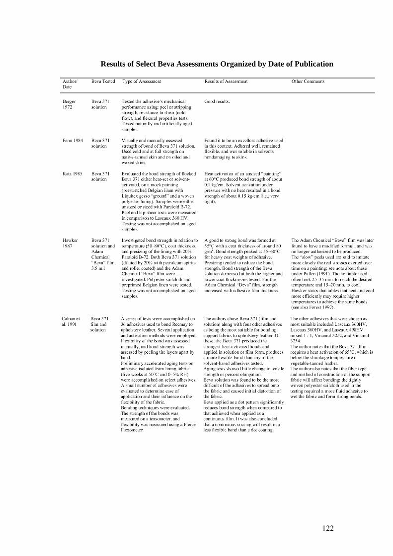
Results of Select Beva Assessments Organized by Date of Publication
122
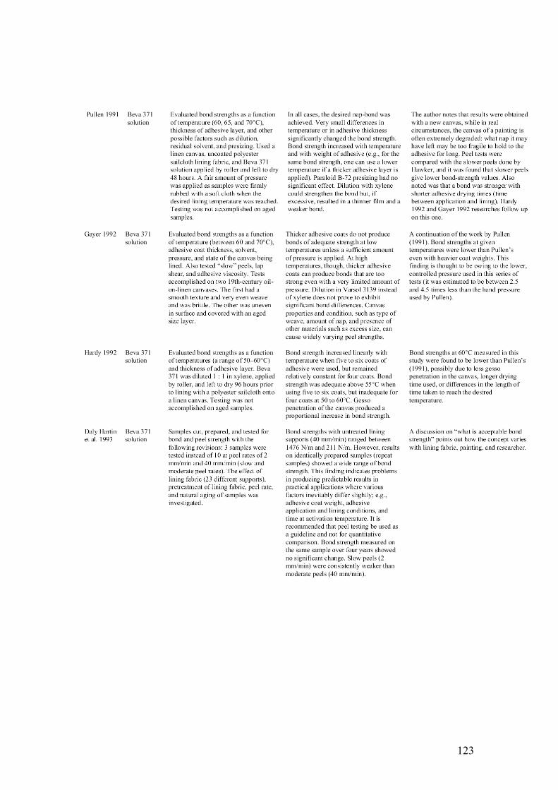
123
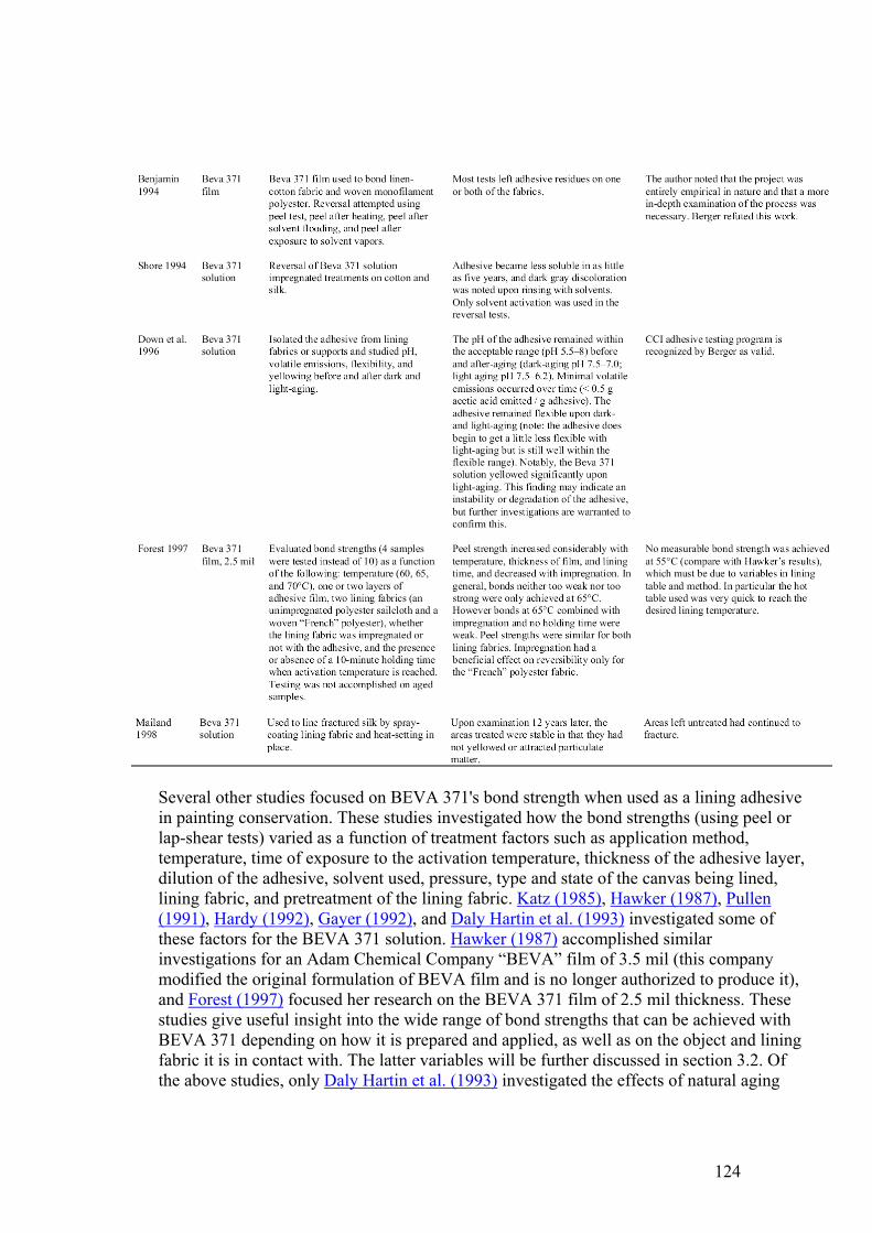
Several other studies focused on BEVA 371's bond strength when used as a lining adhesive in painting conservation. These studies investigated how the bond strengths (using peel or lap-shear tests) varied as a function of treatment factors such as application method, temperature, time of exposure to the activation temperature, thickness of the adhesive layer, dilution of the adhesive, solvent used, pressure, type and state of the canvas being lined, lining fabric, and pretreatment of the lining fabric. Katz (1985), Hawker (1987), Pullen (1991), Hardy (1992), Gayer (1992), and Daly Hartin et al. (1993) investigated some of these factors for the BEVA 371 solution. Hawker (1987) accomplished similar investigations for an Adam Chemical Company “BEVA” film of 3.5 mil (this company modified the original formulation of BEVA film and is no longer authorized to produce it), and Forest (1997) focused her research on the BEVA 371 film of 2.5 mil thickness. These studies give useful insight into the wide range of bond strengths that can be achieved with BEVA 371 depending on how it is prepared and applied, as well as on the object and lining fabric it is in contact with. The latter variables will be further discussed in section 3.2. Of the above studies, only Daly Hartin et al. (1993) investigated the effects of natural aging
124
and found no significant trends in change in strength.
Daly Hartin et al. (1993) also found that identically prepared samples of BEVA solution showed a wide range of bond strengths in spite of the high degree of consistency in sample preparation. Thus even small differences in preparation or application, which one may tend to overlook especially in a practical application, can significantly affect bond strength. Interestingly, the film has provided more consistent bond strengths in terms of a lower standard deviation and coefficient of variation as compared to films made with the solution (Forest 1997), a result that the author explains as due to its even thickness and its ease in application with no delays due to solvent evaporation. In other words, the film provides a better control of the range of bond strengths that can be obtained with BEVA 371. Daly Hartin et al. (1993) give a useful discussion on what is considered “adequate bond strength,” pointing out how the concept varies with the lining fabric, the object, and, subjectively, the practitioner.
Benjamin (1994) conducted a practical study focusing on reversal of the adhesive and found that BEVA 371 used for lining may not be as easily reversed as one might hope, the problems being high strength and adhesive transfer to the painting substrate. The author noted that the project was entirely empirical in nature, and she concluded that a more in-depth examination of the process was necessary. Berger refuted her claim that reversibility of BEVA-lined fabrics is not easy, arguing that Benjamin had not closely followed outlined instructions for its use (Berger 1995).
Once the application of the two BEVA 371 products expanded from paintings conservation to the treatment of skins and leathers, related assessments were carried out that focused on practical issues such as ease of use and compatibility. Fenn (1984) describes BEVA 371 solution as an excellent adhesive when used cold and at full strength on native-tanned skin, as well as on oiled and waxed skins. Calnan et al. (1991) noted several advantages of BEVA 371, whether film or solution: it has one of the lowest activation temperatures (65°C) of the conservation choices of thermoplastic adhesives, it does not remain sticky upon cooling, and it produces flexible bonds. BEVA 371 (solution and film) was among the five adhesives that Calnan et al. found most suitable for bonding support fabrics to upholstery leather, and it produced the strongest heat-activated bonds. Alter-natively, the bond created by BEVA 371 used wet at room temperature was too weak to be measurable on a tensometer. Additionally, the authors set up preliminary accelerated-aging experiments focusing on the BEVA 371 solution isolated from a lining fabric, and they found little change in tensile strength or percent elongation after five weeks at 50°C and 0–5% RH.
Though the use of adhesives in textile conservation is infrequent and can have serious drawbacks, they have been employed when textile conservators are confronted with problematic artifacts, such as degraded painted banners or powdery silk flags. If an adhesive is to be utilized, BEVA 371 solution has been found to have certain advantages: it can be applied sparingly to form a nap-bond without impregnating the fibers, and it is quite flexible. There are reports of its use in the 1970s and 1980s in this context, and published observations can give helpful insights to conservators treating skins and leathers. Of particular interest to this review are reports in which treatments using BEVA 371 were
125
revisited years later. Mailand (1998) used BEVA 371 solution to line flags, costumes, and textile upholstery, and one of these treatments, accomplished in 1984 on a 1890s silk costume, was reexamined in 1996. During the later examination, it was found that the areas treated with BEVA were stable in that they had not yellowed or attracted particulate matter, but areas left untreated had continued to deteriorate, showing increased fracturing, probably from movement of the textile. On the other hand, Shore (1994) states that when conservators attempted reversal of BEVA 371 solution–impregnated treatments on cotton and silk, the adhesive had become less soluble, or cross-linked, in as little as five years. Upon rinsing the fabric with solvent, a dark gray discoloration resulted, visible at both the front and back surfaces.
3 REVIEW OF BEVA 371 APPLICATIONS ON SKIN AND LEATHER
3.1 ADHESIVE PROPERTIES SOUGHT
There are several requirements of an adhesive for use in skin and leather repair. Ideally, the adhesive should be compatible with the substrate in its physical and chemical properties. It should not stain or change the appearance of the skin or leather and should remain flexible to allow movement of the object. The bond should be strong enough to hold the repair and to withstand stresses to which the object will be subjected. Such stresses can be induced by the weight of the skin or leather or through the handling required during mounting, exhibition, or travel. In terms of chemical qualities, an adhesive used for backing repairs should not interact with the substrate. It should be chemically stable and have good aging properties, i.e., it should release no harmful vapors and should not weaken over time. Also, the adhesive should be easily removable without adverse effects on the skin or leather. Thus, a stable adhesive that can create a sufficiently strong, flexible nap-bond would be ideal, as this type of bond minimally penetrates the skin and is most easily removed.
BEVA 371 meets most of these requirements. It can create a nap-bond without saturating the substrate. If required, it can be adapted (e.g., used at higher temperatures) in order to flow and more readily impregnate the substrate. It adheres very well to most skins and leathers. As previously mentioned (Fenn 1984), this characteristic is especially true for skin artifacts treated with wax polishes or oily leather dressings to which most adhesives, particularly water-based ones, will not adhere. Concerning aging or stability, BEVA 371 solution has proved to be highly stable according to the testing accomplished at the CCI, and it is assumed that the same holds for BEVA film. Reversibility can be accomplished by exposure to hexane or heptanes for a short time, in either liquid or vapor form, or by mechanical means, with or without heat (Berger 1976).
Compared to BEVA 371 solution, BEVA 371 film is a more recent product, but it is used increasingly for skin and leather repairs. As was seen in section 2.2, the film has been shown to produce more consistent bonds than the solution and gives a higher degree of control (Forest 1997). In relation to these results are BEVA film's practical advantages over BEVA solution: it requires no preparation time, is easier to apply, and is more even and uniform than any film cast in-house. BEVA solution, on the other hand, may need its thickness built up in layers, a process that requires diluting the solution, warming it up, and
126
applying it on a backing either by rolling, squeegeeing, spraying, or flocking. Sufficient drying time is required between each application.
Although BEVA 371 has been used successfully on numerous occasions for skin and leather treatments (see sec. 3.2), in some cases it will fail to meet the objectives of a treatment or simply not succeed as well as an alternative. It can be helpful to examine the reasons invoked in the literature for not selecting BEVA 371 after its initial testing for a skin or leather repair treatment. Dignard (1989, 1992) mentions that BEVA 371 solution was considered for the treatment of tears in a kayak, but was avoided due to the lack of proper solvent extraction. Also, heat-setting or solvent reactivation in this case was difficult because of limited access to the back. Fenn (1984) reports that BEVA 371 solution used at room temperature did not adhere well to gut artifacts such as Inuit parkas and bags made from caribou stomachs. It also altered the translucency of the thin skin (if heat-set, the adhesive is stronger and becomes transparent, but presumably heat was to be avoided for these vulnerable materials). In these instances, more success was found using water-soluble (Klucel G or Modocoll EK1200) or water-dispersed (Elvace 1874 or CM Bond M2) adhesives. Fenn also describes issues concerning the treatment of buckskin shirts with friable pigments rubbed into their surface. Tests suggested that if these were to be treated with BEVA 371 solution, later attempts at reversal with specific solvents could drive the adhesive into the pigments, thus altering the color through saturation. For these reasons, it was believed that the polyvinyl acetate (PVAC) emulsions may give better results. Kite (1991) reports that in the treatment of an alumtawed fur-skin, the film was tested, and, although it held well, it was visually disturbing and seemed to penetrate the skin, making it look translucent. She ended up using a wheat starch paste–sodium alginate mixture with a paper backing material. For the treatment of a sheepskin lining of a saddle, Selm (1989) found that BEVA 371 solution used in solution or cast as a film (and presumably heat-set) gave a weak join, saturated the leather causing staining, and had an unpleasant, lingering smell. Instead, Paraloid B-72 film cast from a 15% solution in acetone was employed. The acrylic film was applied to Reemay and either heat-set or solvent-reactivated with acetone.
3.2 TEAR REPAIRS
Besides its initial use on paintings and textiles, BEVA 371 solution was also used at a fairly early date on leather, specifically upholstery. Sheetz and Cochran (1978) describe backing an upholstery leather piece with BEVA 371 solution and Stabiltex (now called Tetex). They describe the process:“After the [fill] repairs were made, the leather was turned unfinished side up and lined with a reinforcing material, Stabiltex, a sheer synthetic [polyester] material, both flexible and strong. The Stabiltex was placed over the leather and attached to it with BEVA 371, which was melted over the Stabiltex a small area at a time with a warm tacking iron.” Following this publication, literature on BEVA 371 repairs covers a range of objects, such as leather upholstery, saddles, gilt leather, and wall coverings. Most frequently, the treatments involve a system of applying the adhesive to a backing, or carrier, and heat-setting this “band-age” as a repair or stabilization measure. However, there are many interesting variations. The following review attempts to give a different perspective to the published information on skin and leather tear repairs using BEVA 371 by presenting the treatment variables that researchers have quantified (see table 1) and that practitioners have used to achieve the bond they required. It should be
127
recognized, however, that probably the most important variable in determining the strength of the adhesive bond is the object's surface and condition (Berger 1972).
3.2.1 Variables in Manipulating the Adhesive
The quantity of adhesive plays a major role in bond strength. Lining tests have shown that, when heat-setting at 65°C and 70°C, doubling the thickness of the 2.5 mil BEVA film can double or even triple the peel strength (Forest 1997). An increase in weight in the BEVA 371 solution used in a lining context also results in an increase in bond strength when used at temperatures above 60°C (Pullen 1991; Gayer 1992; Hardy 1992). Pullen (1991) also gives correlations between temperatures and thickness of adhesives; for example, a bond strength achieved at 70°C could be produced at 65°C by using 50% more adhesive. None of the treatment articles that were reviewed specified the coat weight when using BEVA 371 solution. For the film, though, not surprisingly, the thickness is usually specified (as given by the manufacturer).
The most common method of applying BEVA 371 solution to the backing material in skin and leather treatments is to spread it on with a brush, allow it to dry, and, if necessary, reapply the BEVA in successive layers. The adhesive can also be spread by using a roller or a squeegee, or it can be sprayed on. As can be expected, the coat weights achieved using these methods can vary greatly (Hardy 1992). Another method of applying the BEVA 371 solution is to flock it onto the carrier fabric. This method differs from spraying in that it produces cobweb-type filaments of adhesive. Flocking is said to help reduce or better control the amount of adhesive applied. This method has been used for the treatment of deteriorated upholstery leather from two 17th-century chairs, using Reemay as the carrier (Howard and Berry 1995). The prepared backing was heat-set in the form of sutures for tears as well as in the form of a full lining to the back of the upholstery. Dignard and Gordon (1999) also use this flocking technique to apply BEVA 371 solution onto Stabiltex (Tetex). The prepared backings were heat-set to individual tears as well as to the full backside of a degraded and powdery fur trim and collar.
Generally in a conservation repair involving a backing, the adhesive is applied to a carrier and not to the object's surface. However, just as the application of a slight sizing of BEVA 371 to the back of a painting has been found to improve adhesion (Berger 1975), some practitioners have applied BEVA 371 to both the skin/leather and the repair material in order to increase the bond strength. Calnan (1992) used BEVA 371 film on the carrier and BEVA 371 solution as a primer to repair tears in Spanish gilt leather. The prepared lining was heat-set in place. Similarly, Sturge (2000) used BEVA 371 solution on the leather as well as the carrier and heat-set the elements in place. Fenn (1984) describes repairs using BEVA 371 solution applied sparingly on the inside of a weakened buckskin artifact. When the adhesive had almost dried, an equally sparing layer of BEVA solution was spread on the lining material and pressed onto the artifact without heat. It is likely that the success of this practice is due in part to an increase in wetting or contact with the object's surface. Experimental tests to compare these various application practices were accomplished by Calnan et al. (1991). They found good bond strengths (as measured by peel tests) resulted when BEVA 371 solution was heat-set after having been applied to the backing fabric alone, to the new upholstery leather alone, and to both the fabric and the leather. A slightly
128
stronger bond was achieved when the adhesive was applied to the leather alone. However, when the tests were repeated using a thinner, deteriorated leather, the most appropriate bond for BEVA 371 was formed by applying the adhesive to the support fabric only, rather than on the leather only (application to both was not tested in this case). These somewhat contradictory results suggest that the condition of the skin object, and perhaps other treatment variables, plays a large role.
BEVA 371 solution has also been tested and used in leather conservation as a discontinuous film applied to a carrier fabric and heat-set onto the object. The optimum arrangement was found to be a series of 2 mm diameter dots, 1 mm thick, 5 mm apart, in a staggered formation. A 1 mm thick aluminum sheet was used to produce the pattern (Calnan et al. 1991). The theory behind this preparation was to provide the backed leather with more freedom of movement when exposed to a fluctuating climate. Tests performed on this repair technique did show an increased flexibility as compared to a continuous film of adhesive, but, as could be expected, a weaker bond resulted. Such a discontinuous film of BEVA 371 solution was used with Reemay to fully support the front-seat cover of a 19th-century Panhard-Levassor automobile (Calnan 1991). This method of application appears to be rare, as there are few reports of its use in the literature.
The activation temperature used will affect the degree of penetration or impregnation of the adhesive into the substrate and the color change or staining of the substrate. BEVA 371 solution becomes tacky at 55°C, liquid with an aggressive tack at 65°C, and at 70°C produces an even stronger bond (Berger and Russell 2000). In the case of the BEVA 371 film, peel strengths on lined canvases were found to vary considerably within this 15°C range of temperature: at 55°C they were too weak to even be measurable using a tensometer; at 60°C they were too low to ensure acceptable lining for a canvas painting (average of 0.05 N/mm); at 65°C they were on average approximately 10 times higher than at 60°C, falling within what was established as an acceptable strength for linings; and at 70°C they were found to be quite strong, being approximately twice as high as at 65°C (Forest 1997). This direct relationship between bond strength and temperature was also measured for BEVA 371 solution (Pullen 1991; Gayer 1992; Hardy 1992). In view of these results, the performance of hot spatulas or other heating devices becomes very important, in terms of the accuracy of the temperature and of its precision (or variability of the heat delivered). Although such data are not outwardly presented in the treatment literature, it is reasonable to assume that treatment temperatures for skins and leathers have fallen within, or close to, this range, depending on the required results. For example, in the treatment of a very fragile, fragmented ermine fur lining of a cape, Kite (1990) mentions heat-setting BEVA 371 film at 70–75°C using nylon gossamer as the backing material. Similarly, Calnan (1991), in the treatment of elements of the previously mentioned 19th-century automobile upholstery, mentions heat-setting a discontinuous film (dots) of BEVA 371 solution at 70°C. Other reported heat-set treatments using the film include the treatment of torn stitchings within a saddle (Sturge 2000), a variety of skin materials including deerskin drums and lizard natural history specimens (Nieuwenhuizen 1998), a pair of fine suede gloves (Kite 1996), and a leather sedan chair (Selm and Bilson 1992). Heat-set examples employing the solution include the repair of Spanish gilt leather (Calnan 1992), repairs to parts of the above-mentioned 19th-century automobile upholstery (Calnan 1991), and the treatments by Howard and Berry (1995), Dignard and Gordon (1999), and Sheetz and
129
Cochran (1978) mentioned earlier. One case study describes the use of very high temperatures to repair fragmented and weakened vegetable-tanned leather car upholstery. During this treatment, BEVA 371 solution was impregnated into the Reemay backing material and heat-set to the leather at 100°C using a short contact time (Sturge 2000). This is said to have allowed some reshaping of the leather while the BEVA was warm and soft, while producing a strong, secure bond once the adhesive was cool. In the vast majority of cases, such high temperatures are avoided for degraded skins and leathers.
BEVA 371 bonds quasi-instantaneously once the activation temperature is reached (over 60°C), but if the activation temperature is applied for a length of time, the bond strength is significantly affected. In a series of lining tests, Forest (1997) found that, with the hot table used, it took approximately 12, 14, and 18 minutes to reach the activation temperatures of 60, 65, and 70°C respectively, and about 20 minutes to cool back down to room temperature. If a holding time of 10 minutes was added when each activation temperature was reached, a bond of twice the peel strength resulted, as compared to the bond created with no holding time. In particular, it was found that at 65°C with no holding time, the bond was too weak for half of the samples. But, with the 10-minute holding time under the same conditions, the peel strengths ranged between moderate and too strong. Also, it is likely that the rate at which the BEVA 371 is heated and cooled may affect strength (Forest 1997). Holding time was not found to be reported in the treatments surveyed, but it would be expected to be in the range of seconds or tens of seconds rather than minutes. Rate is never mentioned either and most likely varies with the type, quality, and age of the equipment used.
Another treatment variable that affects bond strength but is not often quantified in skin and leather treatments includes the amount of pressure applied (Gayer 1992). In the case of the BEVA 371 solution, the amount of solvent retained or the length of time for solvent evaporation to occur prior to use will also have an impact on bond strength (Hardy 1992).
Conservators have often chosen to use BEVA 371 solution without any heat beyond room temperature to avoid potential heat damage. This technique results in a weaker bond than that achieved through heat-setting (Calnan et al. 1991). In some cases a weak bond is all that is required. Boulton (1986) describes repairs to a pair of Aleutian Islands boots using BEVA 371 solution diluted in toluene, brushed onto goldbeater's skin, and applied at room temperature. Fenn (1984) also mentions the use of BEVA 371 solution without heat with various nonsynthetic backing materials to repair Inuit clothing water-proofed with sea mammal oils and also native-tanned clothing. Kronthal (2001) experimented with BEVA 371 solution at room temperature for some repairs to rawhide shadow figures.
In painting conservation, if temperatures lower than the activation temperature are required, they can be obtained by spraying films of the BEVA 371 with solvents. According to the BEVA 371 film technical data sheet, spraying the film lightly with naphtha makes it tacky at about 38–43°C (methylene chloride is also mentioned, but it is highly toxic). For BEVA 371 solution, the activation temperature can be lowered to 40–45°C or less by lightly spraying with aromatic mineral spirits. It can also be lowered by using the adhesive about two hours after applying it to the backing material, while it still retains some of the solvents (Berger 1975). No references to using BEVA 371 in this way on skins and leathers were
130
found in the literature.
Another method of using BEVA 371 that avoids the use of heat is solvent reactivation of the dry film. The solvent can be sprayed onto the film or, for small repairs, applied with a syringe or a fine brush. If the solvent is applied with a syringe, it becomes possible to position the adhesive-covered carrier behind the object while the adhesive is in a dry state, an advantage shared with the heat-setting technique. The amount of time that good contact must be held through the application of pressure before the bond is achieved can be short, but it depends on the type and quantity of solvent used. In comparison, heat-setting involves quasi-instantaneous bonding time. Solvent reactivation was one of several methods used by Kronthal (2001) in the treatment of shadow puppets. In this context, goldbeater's skin was brushed with the BEVA 371 solution. This solution was left to dry as a film, and the backing and adhesive were applied by reactivation with naphtha or petroleum benzine. Though this technique was sufficient in many cases, a stronger bond was achieved with other adhesives in combination with the gold-beater's skin.
3.2.2 Choice of Lining Material
Many carrier materials have been used for skin and leather repairs, depending on the nature of the substrate and the required results. Their composition, method of construction (woven or nonwoven), and nap can affect the bond strength (Calnan et al. 1991; Gayer 1992; Daly Hartin et al. 1993; Forest 1997; Berger and Russell 2000) as well as flexibility of the repair.
Both spun and woven synthetics have been used successfully, including Stabiltex (Tetex) woven polyester (Sheetz and Cochran 1978; Dignard and Gordon 1999), Hollytex spun polyester (Nieuwenhuizen 1998), Reemay spun polyester (Kaminitz and Levinson 1988; Calnan 1991; Howard and Berry 1995; Nieuwenhuizen 1998; Sturge 2000), Dacron woven polyester taffeta (Tsu et al. 1999), Arvex woven polyester or polyester sailcloth (Calnan 1991; Calnan 1992; Selm and Bilson 1992), and Cerex or nylon gossamer (Kaminitz and Levinson 1988; Kite 1990; Calnan 1991; Selm and Bilson 1992; Kite 1996).
Natural materials have also been used. Tsu et al. (1999) describe repairs to tears within an 18th-century gilt wall hanging using Japanese paper with BEVA 371 solution in combination with the BEVA gel. Fenn (1984) used both new oil-tanned skin and cotton fabric with the BEVA solution in treating native tanned skins (Fenn 1984; Tsu et al. 1999). Skin lining materials, such as goldbeater's skin and natural skin condoms, have also found useful applications. For example, Kronthal (2001) found that the translucent properties of goldbeater's skin matched those of a collection of Chinese shadow puppets while also producing a strong, flexible mend. Boulton (1986) has also used goldbeater's skin with BEVA solution at room temperature to treat Aleutian boots.
3.3 FILLS
One can utilize BEVA 371's thermoplastic properties and flexibility to create a fill material and to replicate textured surfaces. Calnan et al. (1991) investigated a series of possible polymeric fills, including the use of BEVA 371 film. They found that the heated film could be worked to create a flexible and extensible fill and had the following advantages: it
131
requires virtually no drying time, it is easy to reverse with heat or solvents, and it is easily overpainted with acrylic emulsion paints. They also noted that the fill material needed reworking to ensure a smooth finish and uniform adhesion and had a tendency to spill over onto the immediate surrounding leather surface. In this case, the preferred application involved heat activation of small rolls of the film placed in the crevice and building up the fill material in layers to ensure that the adhesive was fully activated and bonded well to the leather. Kaminitz and Levinson (1988) used the solvent form of BEVA 371 mixed with dry pigments and glass microballoons to fill losses in untanned skin stretched over wooden drums and harps. The mixture was applied in a thin layer over an insert of Japanese tissue paper or synthetic web fabric. In this case, considerable strength was required to join the fill material to the very thin edges of the loss, and great flexibility was necessary to allow the skin to respond to environmental changes without separating from the fill. Nieuwenhuizen (1998) mixed warmed BEVA 371 film with dry pigments and glass microballoons and applied it as a fill material to replicate textured surfaces. In this case, the solution was avoided in an attempt to minimize shrinking. Sturge (2000) describes the use of colored BEVA “sticks,” made by mixing small amounts of dry pigment into BEVA 371 solution and allowing the solvents to evaporate after spreading the mixture onto silicone paper. Once dry, the solid BEVA 371 can be cut into strips and melted into cracks and splits using a heated spatula.
4 ASSESSMENTS OF PAST AMNH TREATMENTS OF SKIN
4.1 ADHESIVES USED AND RATIONALE
BEVA 371 was introduced as an adhesive in the objects conservation laboratory at the American Museum of Natural History (AMNH) in 1985. Initially it was utilized in its solution-based form, either applied directly to the edge of the join if it was very small, such as in a butt join of a fringe element, or applied to a lining material and, upon drying, heat-set or solvent-reactivated in place. After BEVA film became available, it soon replaced the solution as the predominant BEVA 371 adhesive form used. A small selection of lining materials has been used with BEVA at the AMNH, primarily Reemay, Cerex, and goldbeater's skin.
Three other types of adhesives were used less frequently on skins during this period. These included polyvinyl acetate (PVAC) resins, Lascaux 498 HV acrylic dispersion, and Paraloid F-10 acrylic resin. Though the PVAC resins (grades AYAA and AYAC) were often favored among these because of their working properties, BEVA 371 heat-set continued to predominate over all choices. It was found that there was increased control over the degree of saturation of BEVA 371 into the substrate and therefore fewer tendencies for the adhesive to stain.
The focus of the evaluation to be described in the next section was to assess the long-term stability of repairs made using BEVA 371. These assessments were made by visual and physical examination of the repairs and the surrounding areas of skin. Some interesting trends were noted during the survey in relation to the other adhesives mentioned above, and these observations will be summarized as well.
132
4.2 ASSESSMENT OF BEVA-BASED TEAR REPAIRS
In 2002, 58 ethnographic skin objects treated during the years 1985 to 2000 using either BEVA 371 or other selected adhesives were reexamined in an attempt to determine the long-term stability of the repairs. The objects surveyed included skin clothing and apparel such as coats, leggings, aprons, bags, and shoes and musical instruments such as drums and harps. The types of skins examined included untanned (rawhide) and tanned (brain, oil and smoked) skins. A total of 49 of the 58 objects in the survey had tear repairs or fills made the BEVA 371 products.
The results of the survey demonstrated that an overwhelming majority of repairs and fills utilizing BEVA 371 were still intact and flexible from 2 to 17 years after treatment. A small number of these objects (5 out of a total of 49, or 10.2%) had repairs that had either failed or were beginning to exhibit minor changes, such as lifting or incipient lifting of the lining material from the substrate. It should be noted that the number of repair sites on an object varied from one to more than a dozen, and if just one backing out of several was beginning to separate, this treatment was counted as exhibiting changes. Of the five objects that exhibited changes indicating failure, three consisted of tear repairs made using BEVA film and two consisted of fills whose media was BEVA solution. No other types of deterioration, such as stiffening or related discoloration of the skin or adhesive, were observed. It is also important to note that all five of the objects exhibiting some degree of repair failure were included in traveling exhibits. As such, these objects were subjected to extensive handling engendered by repeated packing, unpacking, and placement of the objects on mounts.
Of the small number of objects with failed tear repairs (3 out of 40), the cause of the deterioration of each repair can be explained by choices made by the conservators, rather than by aging or deterioration of the adhesive. As previously outlined, many variables can affect bond strength, such as the choice of backing material, the quantity of adhesive applied, the temperature used, and the dwell time. A more precise cause of failure is sometimes difficult to pinpoint. Factors that appeared to promote weak or failed repairs in these cases included poor choice or preparation of the lining materials, inadequate size of lining material, and possibly inadequate preparation of skin surface prior to repair application.
Most commonly, the lining material may not have been properly matched with the weight and flexibility of the object, or the adhesive was insufficiently or inadequately applied to the backing. A thick-grade Reemay was often intuitively chosen as the lining material for large or heavy objects or for repairs on thick, relatively inflexible skins because of its heavier weight and strength. Such a choice was made, for instance, for the repair of a Mangbetu fur belt with numerous heavy dangling ornaments. The linings were applied with BEVA 371 film to stabilize the incipient tears on this object. Examination of the belt revealed that two of the five backings were in the process of completely separating from the surface, and another two linings exhibited lifting around their edges. These results may be partially due to incomplete application of the adhesive all the way to the edges of the
133
backing as well as the use of cut rather than feathered edges. In retrospect, Reemay may sometimes be too thick or tough a lining material for particular objects. It is difficult to feather out and it loses adhesive during the feathering process, therefore providing less contour and grip at its edges. This loss becomes especially problematic for objects that are flexed during handling. Feathering the edges plus using an excess of adhesive at the edges would probably ameliorate much of the edge lifting seen within repairs using Reemay. Furthermore, observation of numerous repairs during the course of this survey indicated that for thick skin objects, such as the Mangbetu belt, application of two layers of Cerex, a thinner backing material, sandwiched with a second layer of BEVA film may provide better longevity.
A complicating factor when analyzing the cause of repair failure as seen on the Mangbetu belt is the fact that the belt was oil-tanned during manufacture and may have retained oily residues on its surface. While BEVA 371 has been recommended as an adhesive for oily or waxy surfaces, it is possible that the residues left on the skin surface of the belt may have compromised the integrity of the mends. Repairs of this type would probably be more successful if the skin were superficially degreased by swabbing with an appropriate solvent for oils prior to application of the BEVA and backing. Additionally, past treatments on objects at AMNH also exhibiting oily surfaces, such as Chinese shadow puppets, indicate that stronger bonds may be obtained through direct application of BEVA 371 solution to the surface of the repair area and, upon drying, heat-setting BEVA film with the appropriate lining.
Examination of numerous repairs and fills applied to a highly deteriorated shaman's apron from the Luba culture of Africa revealed a Cerex backing lifting from the skin surface at one repair site, with a strip of inadequately heated BEVA film remaining as a separate intact layer. Treatment procedures outlined previously such as temperature and exposure time to heat are important factors in these kinds of repairs. As with the choice and preparation of lining materials, conservators should be meticulous about ensuring that a complete bond is achieved during execution of the treatment. Additionally, this object had a number of cut rather than feathered backings that were lifting at their edges. Upon examination of the reverse side of the backings, it was evident that the BEVA film had not been applied all the way to their edges. Even if the edges of a backing are a significant distance from the area requiring support, an inadequately adhered lining edge could lead to further lifting of the lining if the object were to undergo excessive handling.
Another example of repair failure occurred as a result of handling during the course of this survey. A Blackfoot shirt was fit quite snugly on a mannequin. Manipulation to examine a Reemay–BEVA film repair caused the backing to completely detach from one side of the join. It was not clear what the source of this join failure was. While the surface area of the join was adequate, the appearance of the adhesive on the detached backing seemed to indicate that the repair may not have been carried out to a sufficient degree of saturation (as controlled by the dwell time) or with enough heat. Both of these treatment elements would be necessary to ensure a sufficiently strong bond to withstand the handling and continual stress of years on a closely fitted mannequin.
A final source of join failure was observed on another of the artifacts surveyed. In this case
134
a detached tassel of a Blackfoot bag that was repaired prior to travel in a multistop exhibit clearly failed, as neither the tassel nor the lining was extant at the time of the survey. For this repair, the lining material used for the join was probably too small for the requirements or the use of the object. Other remaining tear repairs at less vulnerable locations on the object were extant but were very tiny in size. It should be noted that the lining material must span a sufficiently large area beyond the tear to provide ample surface for the adhesive mend, thus allowing for handling and manipulation of the object.
Most of the failed repairs described above were executed 12 to 17 years ago. It is clear that a history of the use of BEVA over this period of time engendered experimentation with techniques that led to greater finesse in skill. As mentioned, none of the BEVA 371 tear treatments appeared to fail as a result of chemical problems within the adhesive, but instead from specifics concerning inappropriate treatment decisions and procedures chosen for the particular object.
4.3 ASSESSMENT OF BEVA 371–BASED FILLS
Nine of the 58 objects in the survey had applied to them fills that used BEVA 371 solution as the adhesive element. The composition of the fills made to skin or leather objects utilizing BEVA 371 was of two types: those that included glass microballoons as the inert filler and those that included cellulose powder or pulp as the inert filler. Both types of fills were internally colored by the inclusion of dry pigments in their mixtures. These fill mixtures were empirical. They were not formulated according to weighed-out amounts; hence, their properties could vary widely. Too much inclusion of the inert fillers could result in less flexible fills or fills that could separate from the edges of the skin due to inadequate tack or adhesion.
Earlier fills at AMNH consisted of mixtures of BEVA 371 solution mixed with glass microballoons and dry pigments applied over Reemay backings (Kaminitz and Levinson 1988). These fills were often used to replace losses or cracks in rawhide coverings that were stretched over the wooden bodies of musical instruments. Where possible, Reemay or another type of backing was slipped under the skin and held in place using PVAC resin (chosen for its high degree of tack). At times narrow surface cracks in the skin were filled with the mixture in order to achieve visual integration; this was necessarily accomplished without the backing. More often, the BEVA mixture, of thick putty consistency, was applied over the Reemay with a spatula, and upon setting was shaped and textured with a heated spatula. Because there is a high degree of tension in the stretched leather or skin, these instruments are particularly reactive to fluctuations in temperature and relative humidity. Therefore, the fills required sufficient flexibility to allow for movement of the skin over the rigid core and adequate cohesive strength and tack to adhere to the thin edges of the remaining skin.
Of the nine objects with fills that were examined, six were musical instruments treated with BEVA solution–glass microballoon fills. The instruments were on exhibit for 2 years, traveled to several venues, and then spent 10 years in a stable storage environment. During travel, one of the objects with narrow, unbacked fills exhibited separation of the fill from the surrounding skin. It was easily remodeled with a heated spatula to the edges of the skin.
135
During the recent survey, this harp again exhibited slight separation of the same fill from the edges of the skin. Another harp that initially showed severe distortion of the skin and numerous repairs was stable during the length of the exhibit. However, with time the skin has contracted, causing the fill to separate to an unacceptable degree. Thus, the survey revealed that two out of six repairs to objects of this type exhibited some degree of instability. The release of the edges of the fill from the skin appears to be a failure of a physical nature and is not attributed to the chemical stability of the resin. Given that there is so little of the actual adhesive present along the edges of these fills, and given the inordinate amount of strain and flexing that such a repair can undergo, this degree of failure is not surprising. This is especially the case with the fluctuations in temperature and relative humidity posed by travel. Perhaps pretreating the edges of the loss with BEVA 371 solution and then applying the fill material would prevent such failure.
In another early repair, the BEVA 371–glass microballoon fill material was applied directly to the surface of a couple of tassels on the vegetable-tanned skin of an African club, thinly filling surface losses that had resulted from insect grazing. The tassels, though fragile because of such extreme loss, were not backed to lend more strength. Currently, they are intact, though the fills are separating around their edges from the skin. Again, the instability of these fills appears to have nothing to do with a chemical interaction of the adhesive and skin. Instead, it appears to be an example of inadequate choice of repair technique by the conservator in which a simple backing would have better addressed the issue of stability. No matter how much flexibility or tack the adhesive may have, application of a small fill to a very mobile, flexible element will most likely result in separation of fill edges from the substrate.
The second type of fill mixture, consisting of BEVA 371 in solution with cellulose powder or pulp and dry pigments, was developed to be a more flexible fill material. It was used in the laboratory from 1997 to the present, specifically to fill losses in two objects composed of deteriorated skins with sueded surfaces—a Luba shaman's apron and a Yakut shaman's coat. The mixture was used over Reemay or Cerex backings and, in these cases, was applied to objects that required a considerable amount of handling prior to exhibition. The two objects thus treated have remained remarkably stable. The fills currently retain their flexibility, and the adhesion of the fills to the edges of the skin has been sufficient throughout the handling imposed during mount making, packing, and exhibit. It should be noted that the flexibility of this fill material can vary from fill to fill because of the empirical nature of the mixtures. This inconsistency could be easily addressed by using weighed-out formulations to create facsimiles, obtaining more reproducible properties.
4.4 ASSESSMENT OF AYAA AND AYAC (PVAC) RESINS AND LASCAUX 498 HV REPAIRS
Of the 58 objects reexamined in the survey, 10 included repairs made using PVAC resins (AYAA or AYAC) or the acrylic dispersion Lascaux 498 HV consisting of 56% butylacrylate-methylmethacrylate copolymer (Down et al. 1996). Though considerable treatment failure was noted in this group, no conclusions have been made about the reasons for the failure since the sample size is too small and it is outside the scope of this study. However, interesting trends were noticed. Of the seven objects that were repaired using one
136
of the PVAC resins, two had mends that had failed. Visual inspection indicated that the reasons for these failures could be similar to some of the failures seen with BEVA 371 repairs. In one case, the backing size was possibly inadequate for the repair demands of a highly responsive drum skin; in the other, the repair was made using discrete dots rather than a continuous bead, which has been shown to be a weaker repair method. None of the adhesives at these failed joins appeared particularly degraded or yellowed.
Two objects repaired using Lascaux 498 HV were also reexamined, and both exhibited some degree of failure. In one case, the adhesive was chosen because the conservator wanted a weak bond that would release if the area of the mend was under too much pressure. In that sense the treatment could be considered successful, as the repair backing had totally released from the drum skin. In another situation, the synthetic web backing material employed appeared too thin for the weight and flexibility of the object— a large, extremely heavy tipi. Additionally, the adhesive may not have had enough strength for the necessary repairs. The high percentage of failure in this small sample size suggests that further examination and study may be needed.
4.5 SUMMARY OF ASSESSMENT RESULTS
A survey was conducted of nearly 60 skin and leather artifacts at AMNH treated between 1985 and 2000, where the majority of repairs used BEVA 371 film or solution as the adhesive. Results indicated that in most cases the BEVA 371 tear repairs and fills have remained intact: they are visually unchanged, and the mends continue to provide the stability required. Of the 10% that showed any degree of failure, the changes could usually be explained by unsuitable treatment decisions often closely related to how the object would be used in the future. Several factors that could influence the long-term success of these repairs include the nature, size, and thickness of the backing material, the degree of heat used and the time it was applied, and the degree of saturation of the adhesive into the skin and the backing. As expected from its known stability, chemical deterioration of the adhesive does not appear to be at cause. In the few instances where the adhesive failed, or was intentionally reversed to provide a view of the adhesive under the backing material, no yellowing or other discoloration of the adhesive was observed. It is clear that individual treatment procedures and choices are key factors in the longevity of repairs made with this substance.
5 FUTURE ANALYSES
BEVA 371 solution and film have been adopted by objects and ethnographic conservators as adhesive options for treatment repairs, in part because of their known stability. It would be useful to have more information on their long-term aging properties when in contact with skin and leather, specifically the effect the adhesive has on the physical properties of these materials. Additionally, though it has been used successfully for many years on other acidic substrates such as aged canvases, more testing and analysis of its properties when in contact with the acidic environments provided by skin and leather are critical. Conservators at the AMNH and scientists at CCI have begun discussions concerning future efforts to further understanding of the long-term properties of BEVA 371 film when used for skin and leather repair. Three goals have been developed: to determine how BEVA 371 ages in
137
the acidic context of vegetable-tanned leather; to determine the effects the aged adhesive has on the skin; and to determine if, upon aging, there are changes to the bond between the adhesive and the skin. Most of the experiments will closely follow methodologies laid out by CCI in its ongoing adhesive studies of PVAC and acrylic resins and will complement analysis to be accomplished from sampling from the AMNH collections. The AMNH project will involve removing both adhesive and skin samples from artifacts treated with BEVA 371. Shrinkage temperature measurements will be accomplished on collagen samples taken from untreated areas of artifacts and will be compared with those taken from reversed repairs, where the adhesive was in contact with the fibers. It is believed that this could help determine if the adhesive had a deteriorating effect on the skin.
6 CONCLUSION
The literature on adhesive repair treatments using BEVA 371 was reviewed to provide an overview of the broad range of applications that the adhesive has had with skin and leather objects over the years and the many variables that can affect the outcome of the treatment. Understanding the physical and chemical properties of BEVA 371 solution and film has allowed conservators the ability to manipulate the adhesive and its application methods to accomplish the needs required by a wide range of materials. Comparing results of the literature survey to actual assessments on collections has provided insights into how the repairs actually respond over time to these variables as well as to external forces. In the rare cases where failures were observed, it was concluded that these were due to poor treatment decisions and an underestimation of the bond strength required to withstand handling, not to chemical deterioration of the adhesive. A CCI-AMNH collaborative project is planned to further investigate the properties of BEVA 371 film used in contact with acidic skins and leathers.
ACKNOWLEDGEMENTS
The authors would like to thank those conservators and conservation scientists who have published their experiences and research concerning the use and properties of BEVA 371 in paintings, textiles, and objects conservation. Making these results available has allowed for a more comprehensive understanding of this material.
In addition, the following colleagues who reviewed this article and provided useful comment are gratefully acknowledged: Debra Daly Hartin of the Canadian Conservation Institute, Elisabeth Forest of the Centre de conservation du Québec, and Monika Harter of the Adelhauser Museum in Freiburg, Germany. Most especially, we extend our appreciation to Gustav Berger for the development, introduction, and analysis of an adhesive very useful to the field.
138
REFERENCES
Benjamin, R.1994. The separation of two fabrics bonded together with BEVA 371. Picture Restorer.6: 5–7. Berger, G.1970. A new adhesive for the consolidation of paintings, drawings and textiles. International Institute for Conservation: Bulletin of the American Group11(1):36–38. Berger, G.1972. Testing adhesives for the consolidation of paintings. Studies in Conservation17:173–94. Berger, G.1975. Heat-seal lining of a torn painting with BEVA 371. Studies in Conservation20:126–51. Berger, G.1976. Formulating adhesives for the conservation of paintings. In Conservation and restoration of pictorial art, ed. N. S.Brommelle et al. London: Butterworths. 169–81. Berger, G.1984. The procedure of developing an adhesive for paintings: The importance of valid tests. In Adhesives and Consolidants,ed. N. S.Brommelle et al. London: International Institute for Conservation of Historic and Artistic Works. 13–17. Berger, G.1995. Letter to the editor. Picture Restorer7: 26–28. Berger, G., and W.Russell. 2000. Conservation of paintings: Research and innovation.London: Archetype Publications. Boulton, A.1986. The examination, treatment, and analysis of a pair of boots from the Aleutian Islands including a note about possible pesticide contamination. Journal of the American Institute for Conservation25(1):1–13. Calnan, C.1991. Conservation of leather upholstery on the 1894 Panhard-Levassor Motor Car at the Science Museum. In Conservation of leather in transport collections, ed. ChristopherCalnan. London: UKIC. 31–34. Calnan, C.1992. The conservation of Spanish gilt leather: An introduction. In Conservation of the Iberian and Latin American Cultural Heritage,ed. H. W. M.Hodges, John S.Mills, PerrySmith. London: International Institute for Conservation of Historic and Artistic Works. 23–26. Calnan, C., R.Selm, and B.Haines. 1991. Conservation of automobile and carriage leathers. UKIC Conservation News11(September): 1–30. Daly Hartin, D., S.Michalski, and C.Pacquet. 1993. Ongoing research in the CCI lining project: Peel testing of BEVA 371 and wax-resin adhesives with different lining supports. ICOM Committee for Conservation preprints, 10th Triennial Meeting, Paris. Washington, D. C.: ICOM. 128–34. Dignard, C.1989. La reparation des peaux d'un kayak. Proceedings of the IIC-Canadian Group 14 th Annual Conference, Toronto, Canada, ed. JohannaG.Wellheiser. Toronto: IIC-CG. 159–67. Dignard, C.1992. Tear repair of skins with minimal access to their backs: The treatment of a kayak. Leather Conservation News7(2):1–8. Dignard, C., and G.Gordon. 1999. Metal ion catalyzed oxidation of skin: Treatment of the fur trim and collar on a velvet cape. Journal of the Canadian Institute for
139
Conservation24:11–22. Down, J. L., M. A.MacDonald, J.Tetreault, and R. S.Williams. 1992. Adhesive testing at the Canadian Conservation Institute: An evaluation of selected poly(vinyl acetate) and acrylic adhesives.Environment and Deterioration Research Report 1603. Ottawa: Canadian Conservation Institute. Down, J. L., M. A.MacDonald, J. Tétreault, and R. S.Williams. 1996. Adhesive testing at the Canadian Conservation Institute: An evaluation of selected poly(vinyl acetate) and acrylic adhesives. Studies in Conservation41(1):19–44. Fenn, J.1984. Some practical aspects in the choice of synthetic resins for the repair of ethnographic skin and gut. In Adhesives and Consolidants,ed. N. S.Brommelle et al. London: International Institute for Conservation of Historic and Artistic Works. 138–40. Forest, E.1997. BEVA 371 Film linings: Variables affecting bond strength. Master of arts conservation research report, Queen's University, Kingston, Canada. Gayer, J.1992. The effects of variables on the bond strength of BEVA 371 linings: Further study. Master of arts conservation research report, Queen's University, Kingston, Canada. Hackney, S., and T.Ernst. 1994. The applicability of alkaline reserves to painting canvases in Preventive conservation: Practice, theory and research,ed. A.Roy and P.Smith. London: International Institute for Conservation of Historic and Artistic Works. 223–27. Hardy, K. A.1992. The effects of temperature and adhesive thickness on the bond strengths of BEVA 371 lining. Master of arts conservation research report, Queen's University, Kingston, Canada. Hawker, J. J.1987. The bond strength of two hot table lining adhesives: BEVA 371 and Plextol D360. ICOM Committee for Conservation preprints, 8th Triennial Meeting, Sydney. Marina del Rey, Calif.: ICOM. 1:161–68. Howard, B., and A.Berry. 1995. Three chairs for leather conservation. Objects Specialty Group postprints 3. American Institute for Conservation, 23rd Annual Meeting, St. Paul. Washington, D.C.: AIC. 3–9. Kaminitz, M., and J.Levinson. 1988. The conservation of ethnographic skin objects at the American Museum of Natural History. Leather Conservation News5(fall): 1–7. Katz, K.1985. The quantitative testing and comparisons of peel and lap/shear for Lascaux 360 H. V. and BEVA 371. Journal of the American Institute for Conservation24(2):60–68. Kite, M.1990. A 1740's horse hair hat, a busby c. 1827 and a furlined cape c. 1936. ICOM Committee for Conservation preprints, 9th Triennial Meeting, Dresden. Paris: ICOM. 2:616–21. Kite, M.1991. The conservation of a wet weather hat from the uniform of a marshal general of the Portuguese army, and a Chinese furlined kesi robe c. 1800. In Paper and textiles: The common ground, preprints of the conference held at the Burrell Collection, Glasgow. Scottish Society for Conservation and Restoration, United Kingdom. 105–15. Kite, M.1996. Gloves. ICOM Committee for Conservation preprints, 11th Triennial Meeting, Edinburgh. London: ICOM. 2:635–741. Kronthal, L.2001. Conservation of Chinese shadow figures: Investigations into their manufacture, storage, and treatment. Journal of the American Institute for Conservation40(1):1–14.
140
Larsen, R.1994. Summary, discussion and conclusion. In STEP leather project: Evaluation of the correlation between natural and artificial aging of vegetable tanned leather and determination of parameters for standardization of an artificial aging method, ed. R.Larsenwith assistance from M. Vest and U. ABogvad Kejser. Protection and Conservation of European Cultural Heritage Research Report 1. Copenhagen Royal Danish Academy of Fine Arts, School of Conservation. 165–80. Mailand, H.1998. Re-evaluating the application of ethylene vinyl resin based adhesive for treating textiles and costumes. In Adhesive treatments revisited, ed. J.Lewis. London: United Kingdom Institute for Conservation. 31–36. Nieuwenhuizen, L.1998. Synthetic fill materials for skin, leather, and furs. Journal of the American Institute for Conservation37(1):135–45. Pullen, S.1991. The effect of variables on the bond strength of BEVA 371 linings. Master of arts conservation research report, Queen's University, Kingston, Canada. Selm, R.1989. The conservation of a 17th century European padded saddle. In International Leather and Parchment Symposium Preprints. Offenbach am Main, Germany: ICOM-CC Leathercraft and Related Objects Working Group. 265–79. Selm, R., and T.Bilson. 1992. The conservation of an eighteenth century sedan chair. In Conservation of leathercraft and related objects: Interim symposium at the Victoria & Albert Museum. London: ICOM Committee for Conservation. 45–48. Sheetz, R., and A.Cochran. 1978. A method of stabilizing weakened upholstery leather. Studies in Conservation23:86–89. Shore, S. K.1994. Review of loss compensation techniques used in textile conservation. Loss Compensation Symposium postprints, Western Association for Art Conservation Annual Meeting, Seattle. Seattle: WAAC: 21. Sturge, T.2000. The conservation of leather artifacts: Case studies from the Leather Conservation Centre. Northampton, U. K.: Leather Conservation Centre. Tsu, C., D.Fullick, V.Talland, and B.Mangum. 1999. The conservation of gilt leather wall hangings at the Isabella Stewart Gardner Museum. Part II. ICOM Committee for Conservation preprints, 12th Triennial Meeting, Lyons. London: ICOM. 2:708–13.
SUPPLIERS
Paraloid F-10 Rohm and Haas Co. Independence Mall West Philadelphia, Pa. 19126 BEVA 371 film (1 mil and 2.5 mil) Conservator's Products Company P.O. Box 411 Chatham, N.J. 07928 BEVA 371 solution Conservator's Products Company P.O. Box 411 Chatham, N.J. 07928 Cellulose powder Whatman cellulose powder for partition chromatography Fisher Scientific 4500 Turnberry Dr. Hanover Park, Il. 60103 (630) 259-1200 (800) 772-6733 www.fishersci.com Cerex—nylon gossamer
141
Talas 568 Broadway New York, N.Y. 10012 (212) 219–0770 www.talasonline.com Glass microballoons, 3M Scotchlite glass bubbles, goldbeater's skin Talas 568 Broadway New York, N.Y. 10012 (212) 219–0770 www.talasonline.com Hollytex—spun polyester Talas 568 Broadway New York, N.Y. 10012 (212) 219–0770 www.talasonline.com Lascaux 498HV Talas 568 Broadway New York, N.Y. 10012 (212) 219–0770 www.talasonline.com Paper pulp, 289 pulp, ash-free analytical filter paper Schleicher and Schuell Keene, N.H. 03431 Reemay—spun polyester Talas 568 Broadway New York, N.Y. 10012 (212) 219–0770 www.talasonline.com
AUTHOR INFORMATION
LISA KRONTHAL received a B.A. in art history from the University of Rochester in 1988 and an M.A and certificate of advanced study in art conservation from the State University College at Buffalo in 1993. She began working at the American Museum of Natural History in 1994 as a conservator in the Anthropology Division specializing in archae-ological and ethnographic objects and is currently the conservator of Natural Sciences Collections working out of the Office of the Associate Dean of Science for Collections. She is a professional associate of AIC and currently cochairs the conservation committee within the Society for the Preservation of Natural History Collections (SPNHC). Address: American Museum of Natural History, 79th Street at Central Park West, New York, N.Y. 10024.
JUDITH LEVINSON received a B.A. with honors in anthropology from the University of Pennsylvania (1973), a master's of fine arts (1977) from the Cran-brook Academy of Art, an M.A. in art history and a certificate in conservation from New York University, as well as a certificate in objects conservation from Harvard University, Fogg Art Museum. She has worked as head conservator in the Anthropology Department at the American Museum of Natural History since 1985 and has been an adjunct professor of conservation at the Conservation Center, New York University, since 1989. Address: Anthropology Department, American Museum of Natural History, 79th Street at Central Park West, New York, N.Y. 10024.
CAROLE DIGNARD has a B.Sc. in physics and Italian (1981) and an honors B.A in classical studies (1983) from the University of Ottawa, and a master's degree in art conservation (1986) from Queen's University. She has been working in the objects section of the Canadian Conservation Institute since 1988. She is a professional associate of AIC (1993) and an accredited member of the Canadian Association of Professional Conservators (1994). She was one of the instructors of the Canadian Conservation Institute's workshop “Adhesives for Textiles and Leather Conservation: Research and Application,” which was delivered four times between 1999 and 2001. Address: Canadian
142
Conservation Institute, 1030 Innes Road, Ottawa, Ontario, Canada K1A 0M5
ESTHER CHAO graduated summa cum laude from the University of Arizona with a B.A. in anthropology and a B.A. in art history in 1996. She received an M.A. in art history and a certificate in art conservation from the Conservation Center, Institute of Fine Arts, New York University, in 2001, specializing in objects conservation. She completed her fourth-year internship at the American Museum of Natural History and is an Andrew W. Mellon Fellow at the Smithsonian Institution's National Museum of the American Indian. She is currently working in the conservation laboratory at the Peabody Museum, Harvard University. Address: Peabody Museum, Harvard University, Conservation Department, 11 Divinity Ave., Cambridge, Mass. 02138
JANE L. DOWN graduated from Queen's University, Kingston, Ontario, with an honors B.Sc. in chemistry and mathematics in 1973. In 1978, she joined the Canadian Conservation Institute (CCI) and is the senior conservation scientist who is responsible for all adhesive research done at the institute as well as answering the numerous adhesive-related inquiries that CCI receives worldwide each year. She has published many papers and articles on adhesives, presented her work at various national and international conferences, and organized and taught several adhesive workshops, including CCI's “Adhesives for Textile and Leather Conservation: Research and Application.” She is an accredited member of the Canadian Association of Professional Conservators and a Fellow of the International Institute for Conservation of Historic and Artistic Works. Address as for Dignard.
143