Embed Size (px)
Citation preview

CricketSat Construction
CricketSat Assembly 2
Parts List
Monday June14, 2013
9/12/2012
Version10.0
Sch
Part Category Desig Part Description Part Type/ Value QTY
Capacitor C1,C2,C5 Capacitor CAP,CERM,DISC,.1uF,25V,20% 3
C3 Capacitor Film Capacitors 0.033uF Polypropylene 3% 1
C4 Capacitor CAP,MONO,1uF,50V,20% 1
Switch SW1 SPST Slide SW SWITCH,SLIDE,MIN,SINGLE POLE DOUBLE THROW (SPDT),ON-ON,PCB MTG,[email protected],LEAD 3mm SPC1
LED D1 LED , RED LED,RED,660NM,T-1 3/4 1
Thermistor Ra(R2) Thermistor 10k THERMISTOR,NTC,K(+/-10%) 1
Resistor Rb(R1) Resistor, Carbon 2.7k RESISTOR,CARBON FILM,2.7K OHM,1/4 WATT,5% 1
Resistor R3, R4 Resistor, Carbon,330 ohmsRESISTOR,CARBON FILM,330 OHM,1/4 WATT,5% 2
IC 555 U1 LM555CN timer IC LM555, IC Timer 1
IC Socket J1 Socket SOCKET,IC,08PIN,DUAL WIPE,SOLDERTAIL,LOW PROFILE(10)0.30 INCH WIDTH1
Socket J2 Single In-Line Female Socket4 Pin .100" Machined Socket 1
Connector BC1 Male 9v battery connector 1
Connector BC2 Female 9v battery connector 1
Thermistor Ext. Thermistor Extension WIRE,AWG 24/2,TWISTD,RED/WHT 1
Transmitter U1 TX433 433 MHz Transmitter Module 1
PCB PCB Printed Circuit Board CricketSat PCB 1
Antennas Antennas 18 AWG wire -6.8" long 2
Battery B1 9v Battery 1
Cover Therm Cover 1" HEAT SHRINK,FIT-221B-1/8-Yellow 2
Cover Therm Cover 1" HEAT SHRINK,FIT-221B-3/16-Yellow 1
Rubber bands - used to hold battery on
Roll masking tape - used between battery and PCB to keep battery from shorting out PCB
CricketSat Part List
CricketSat Assembly 3
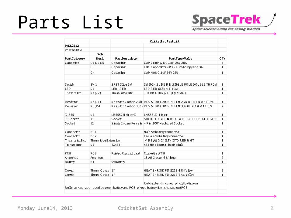
Altium
Monday June14, 2013

CricketSat Assembly 4
Schematic
Monday June14, 2013
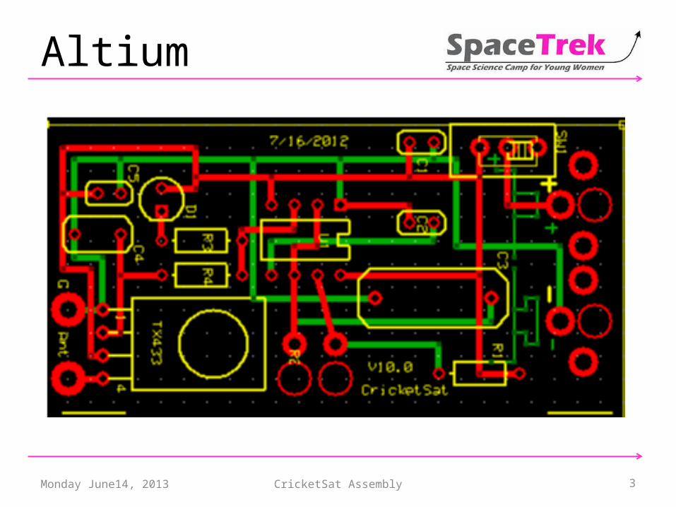
Follow the GUIDE
Monday June14, 2013 CricketSat Assembly 5
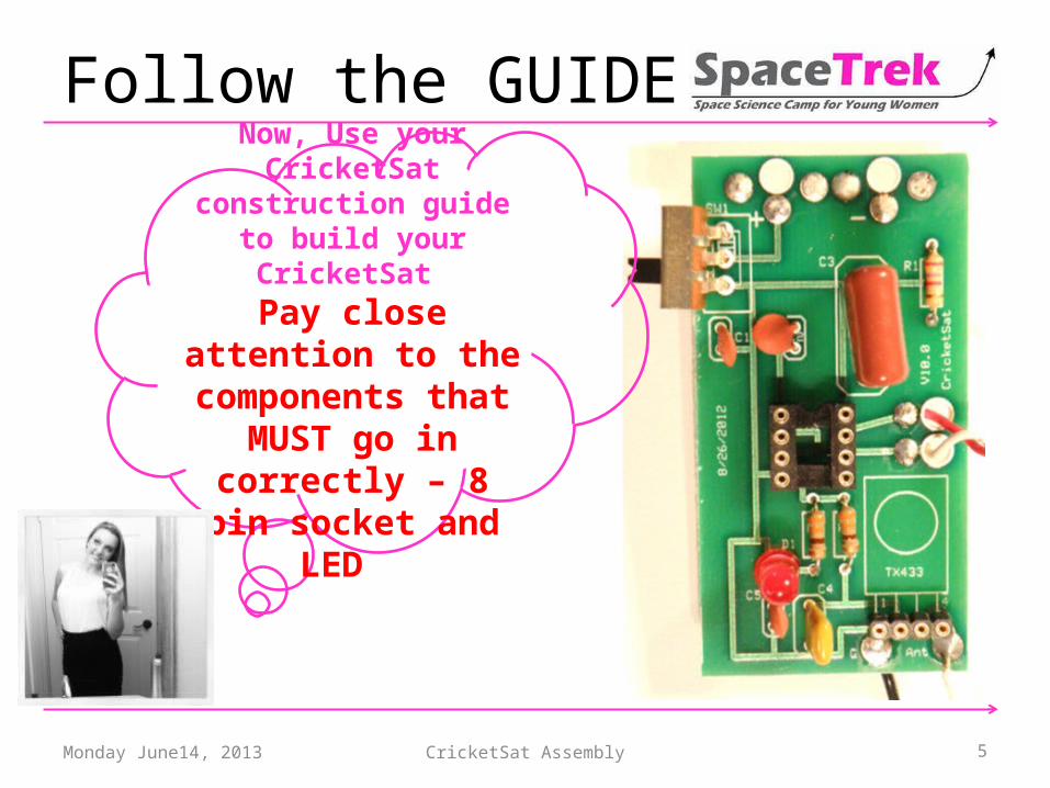
Now, Use your CricketSat
construction guide to build your CricketSat
Pay close attention to the components that
MUST go in correctly – 8 pin socket and LED
Follow the GUIDE
Monday June14, 2013 CricketSat Assembly 6
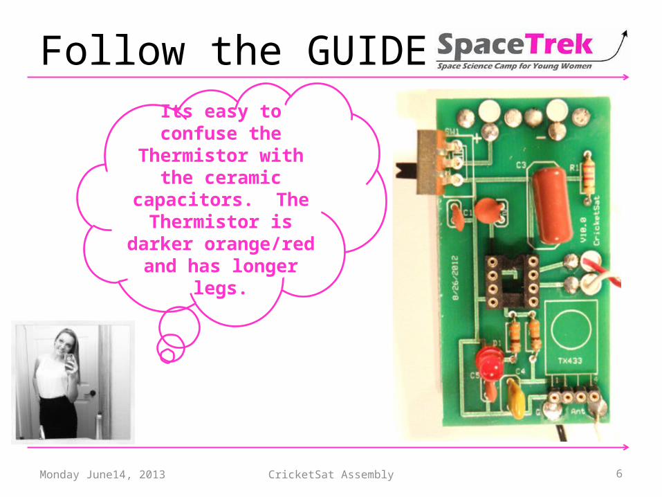
Its easy to confuse the Thermistor with the
ceramic capacitors. The Thermistor is darker orange/red and has
longer legs.

CricketSat Assembly 7
Tips for the thermistor
Monday June14, 2013
The thermistor (R2) is connected here.
CricketSat Assembly 8
Trouble Shooting
Monday June14, 2013
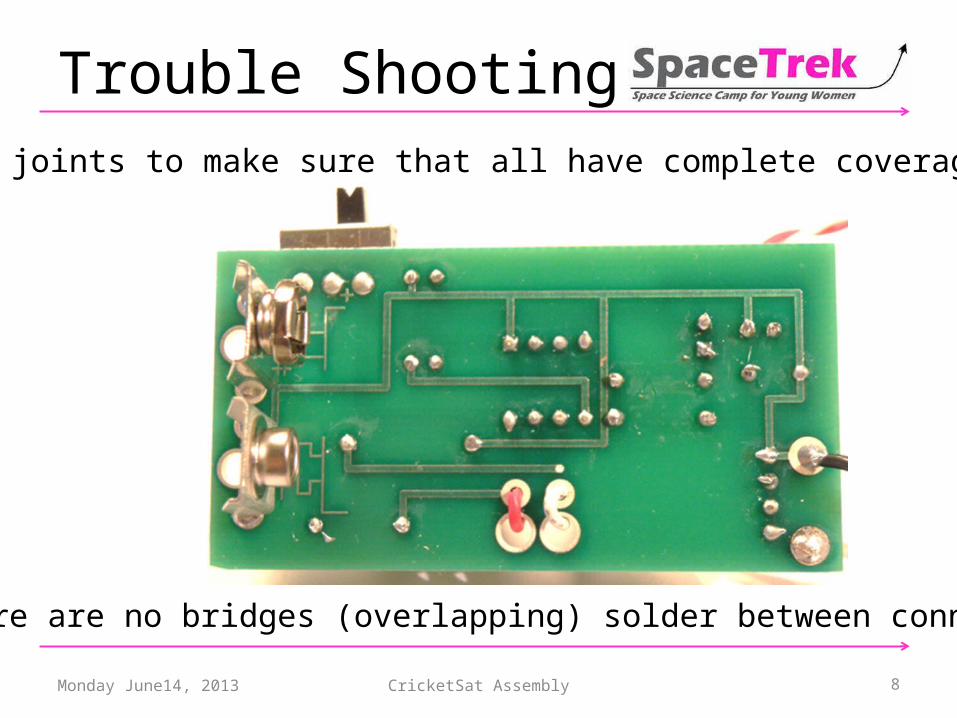
Check all solder joints to make sure that all have complete coverage of the via.
Make sure there are no bridges (overlapping) solder between connections.

CricketSat Assembly 9Monday June14, 2013
Once you’ve successfully completed the build of your
CricketSat – take lots of selfies with your CricketSat
and post!!

CricketSat Assembly 10Monday June14, 2013

CricketSat Assembly 11Monday June14, 2013

CricketSat Assembly 12Monday June14, 2013

CricketSat Assembly 13Monday June14, 2013

1. Tum the switch on in this position. 2. If the LED lights up, go
to the next page.
.3 If the LED does not lights up, you got big troubles, but we will tell you how to fix it. See page 13 for trouble shooting your CricketSat.
Off
On

1. Turn multimeter to Hz%.
2. Connect black lead to pin 1 of J2, Connect red lead to pin 2 of Je.3. You should read between 1,1000 and 1500 HZ. If you do, you are now ready to calibrate your CricketSat – another document.
4. IF you read zero Hz, then go to page 13 to trouble shoot your CricketSat.
Off
On
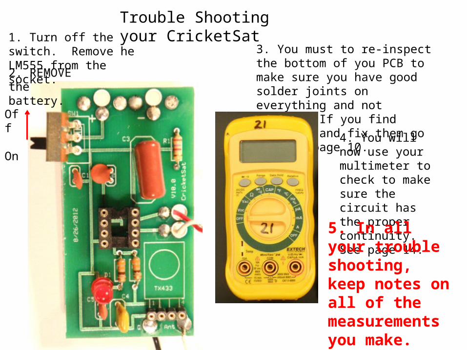
1. Turn off the switch. Remove he LM555 from the socket.
3. You must to re-inspect the bottom of you PCB to make sure you have good solder joints on everything and not bridges. If you find problems and fix them go back to page 10. 4. You will now
use your multimeter to check to make sure the circuit has the proper continuity. See page 14.
Trouble Shooting your CricketSat
Off
On
2. REMOVE the battery.
5. In all your trouble shooting, keep notes on all of the measurements you make.

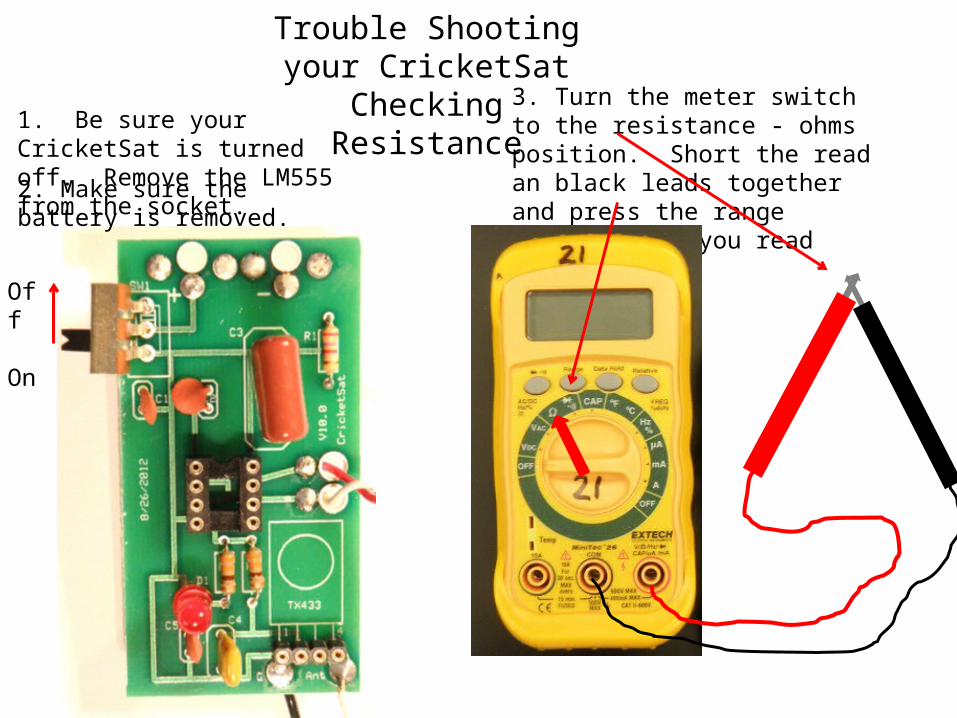
1. Be sure your CricketSat is turned off. Remove the LM555 from the socket.
3. Turn the meter switch to the diode/buzzer position. Short the read an black leads together and press the diode/busser button until you hear the buzzer.
Trouble Shooting your CricketSat
Checking continuity
Off
On
2. REMOVE the battery.

1. Put the multimeter lead in the socket pins 4 and 8. See pin labeling below, right. Buzzer should sound.
3. If you do not get continuity, then check the PCB to determine what is wrong.
Trouble Shooting your CricketSat
Checking continuity
Off
On
2. These pins are connected together on the PCB (see schematic circled) and thus shorted or have continuity between them.
1234
8765
4. Continue checking other pins:
2-6Ground on PCB to other pins:
To J2 pin 1To J1 pin 1
1. Be sure your CricketSat is turned off. Remove the LM555 from the socket.
3. Turn the meter switch to the resistance - ohms position. Short the read an black leads together and press the range button until you read zero.
Trouble Shooting your CricketSat
Checking Resistance
Off
On
2. Make sure the battery is removed.
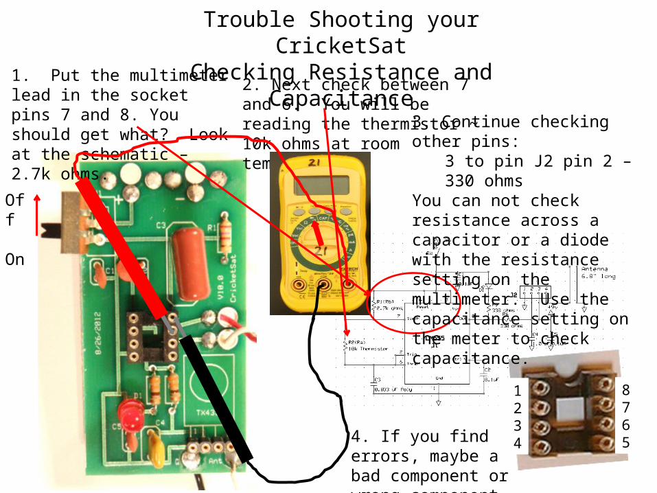
1. Put the multimeter lead in the socket pins 7 and 8. You should get what? Look at the schematic – 2.7k ohms.
Trouble Shooting your CricketSat
Checking Resistance and Capacitance
Off
On
2. Next check between 7 and 6. You will be reading the thermistor ~ 10k ohms at room temperature.
1234
8765
3. Continue checking other pins:
3 to pin J2 pin 2 – 330 ohms
You can not check resistance across a capacitor or a diode with the resistance setting on the multimeter. Use the capacitance setting on the meter to check capacitance.
4. If you find errors, maybe a bad component or wrong component.

1. Put the battery back in and turn the switch on.
Trouble Shooting your CricketSat
Checking Voltages
Off
On
2. Turn the meter to Vdc and check between pins 1 and 8 on the LM555 socket. You should get approx. minus 9v. Minus because the red lead is on the ground connection. If voltage is below 9v, change batteries.
3. Look at the schematic and determine other places where you should also get 9v. If no voltage, trouble shoot. What is cause?
4. If you find errors, maybe a bad components. wrong components or bad connections.