Embed Size (px)
Citation preview

Beriev Be‐200ES‐E Special Conditions (CRI extracts)
Disclaimer – This document is not exhaustive and it will be updated gradually. Page 1
CRI B-05 – Waterborne Operations
REQUIREMENTS: AIC AR Aviation Regulations 25 (1994) & FAR Part 25 Amendment 119 Effective 5 November 2006 & Certification Basis of BE-200ES-E Type Amphibian Aircraft no 200-1/05 approved 12-08-2005
AFFECTED PARAGRAPHS: 25.239
ADVISORY MATERIAL: nil
AR25.239 Spray characteristics, control, and stability on water.
(a) For seaplanes and amphibians, during takeoff, taxiing, and landing, and in the conditions set forth in paragraph (b) of this section, there may be no -
(1) Spray characteristics that would impair the pilot's view, cause damage, or result in the taking in of an undue quantity of water;
(2) Dangerously uncontrollable porpoising, bounding, or swinging tendency; or
(3) Immersion of auxiliary floats or sponsons, wing tips, propeller blades, or other parts not designed to withstand the resulting water loads.
(b) Compliance with the requirements of paragraph (a) of this section must be shown -
(1) In water conditions, from smooth to the most adverse condition established in accordance with JAR25.231.
(2) In wind and cross-wind velocities, water currents, and associated waves and swells that may reasonably be expected in operation on water;
(3) At speeds that may reasonably be expected in operation on water;
(4) With sudden failure of the critical engine at any time while on water; and
(5) At each weight and center of gravity position, relevant to each operating condition, within the range of loading conditions for which certification is requested.
(c) In the water conditions of paragraph (b) of this section, and in the corresponding wind conditions, the seaplane or amphibian must be able to drift for five minutes with engines inoperative, aided, if necessary, by a sea anchor.
2. Spray Characteristics, Stability and Control During Scooping
The proposed standard is technically identical to AIC AR special condition CTY/B-4:
Amphibian aircraft with water scoops extended shall meet the requirements of subparagraph (a) of AR25.239 given above. Compliance with the requirements of subparagraph (a) shall be shown:
(1) under all conditions specified in subparagraph (b) of AR25.239 given above. (2) after sudden failure of the water scoop retraction system at any moment during contact
with the water surface.
3. Minimum Control Speed on Water
The proposed standard is technically identical to AIC AR special condition CTY/B-10:
Renumber subparagraphs (f) to (i) of JAR25.149 as (g) to (j) and insert the following as subparagraph (f):
(f) Water minimum control speed VMCW.
Water minimum control speed VMCW is the calibrated airspeed during take-off run on water, which enables the application of aerodynamic controls solely to completely

Beriev Be‐200ES‐E Special Conditions (CRI extracts)
Disclaimer – This document is not exhaustive and it will be updated gradually. Page 2
counteract yaw and pitch moments, which arise in case of the critical engine sudden failure.
VMCW speed must be established with:
(i) the aircraft in the normal water take-off configuration;
(ii) maximum available thrust of the engines;
(iii) most unfavorable CG position and take-off weight;
(iv) the aircraft is trimmed for take-off;
(v) The value of VMCW , so determined, must comply with the take-off conditions with the cross-wind of 3 m/sec (6 Kts) blowing at 900 with respect to take-off direction on side of the failed engine.
4. Minimum Control Speed on Water During Scooping
The proposed standard is based on AIC AR special condition CTY/B-11 modified as discussed at the meetings 4th-6th August 2006:
The minimum speed of water scooping when skimming V(minwt) must be such that if the critical engine is suddenly made inoperative, the aircraft can safely achieve a positive climb gradient without sinking back into the water.
5. Failure of Water Rudder
The proposed standard is technically identical to AIC AR special condition CTY/D-1:
Seaplane water manoeuvring hydrodynamic devices control system shall comply with JAR 25.671(a,b).
After single failures in mechanical system (except jamming), electrical system or hydraulic system, the hydrodynamic devices for seaplane manoeuvring on water shall be set to neutral position, and shall be kept in this position till the end of flight. With the system jammed in any position different from the neutral one, the pilots shall be warned against landing on water. The warning shall be of the type that produces a powerful attention-arresting effect.
Seaplane water manoeuvring hydrodynamic devices control system shall include provisions for indication of its engaged condition. This indication shall draw the pilots’ attention to the necessity of the system disengagement prior to landing on water.
6. Landing Gear Warnings
The proposed standard is technically similar to AIC AR special condition CTY/D-2. The proposed standard is less specific than CTY/D-2 as it would allow a different aural warning to be given for incorrect gear position when landing on the ground to that given when landing on water.
D-2.1 In case Landing on ground is attempted with landing gear not locked down, or in case landing on water is attempted with landing gear not locked up and landing gear doors not closed, the crew shall hear a continuously or periodically recurring audio warning.
D-2.2 The warning shall be activated at the moment when a sufficient amount of time is left for landing gear down-locking in case of landing on ground, or for landing gear up-locking and landing gear doors closing in case of landing on water, or for go-around.
D-2.3 The aircraft shall NOT be provided with any manual switch which could be easily accessible to the crew and could be engaged instinctively, inadvertently or by a habitual reflex action, and could thus cause disengagement of the warning system operating as per subparagraph D-2.1 of this paragraph.
D-2.4 The warning generation system shall be designed in such a way as to eliminate possibility of false or untimely warning activation.

Beriev Be‐200ES‐E Special Conditions (CRI extracts)
Disclaimer – This document is not exhaustive and it will be updated gradually. Page 3
D-2.5 Such failures in landing gear warning generation system as to interfere with aural warning activation shall be practically improbable.
D-2.6 The aircraft emergency power supply source shall supply power to warning device specified in subparagraph D-2.1 of this paragraph.
D-2.7 Warning to extend/retract landing gear shall be activated at attempt of landing on the ground with landing gear not locked down, or at attempt of landing on water with landing gear not locked up or landing gear doors not closed. The warning to extend/retract landing gear shall be heard at the approach stages specified in the Flight Manual, including abnormal situations which are not considered “practically improbable”.
Redundancy of the warning shall be provided via light indication channel which shall use parameters of independent system.
The warning shall be provided via at least two channels which shall use different parameters of independent systems.

Beriev Be‐200ES‐E Special Conditions (CRI extracts)
Disclaimer – This document is not exhaustive and it will be updated gradually. Page 4
CRI B-09 – Static Longitudinal Stability
REQUIREMENTS: AIC AR Aviation Regulations 25 (1994) & JAR 25 Change 14
AFFECTED PARAGRAPHS: 25.171, 25.173 and 25.175
ADVISORY MATERIAL: nil
The requirements related to static longitudinal stability in JAR 25.171 together with JAR 25.173 and 25.175 shall not apply. The aircraft shall be shown to have suitable stability in any condition normally encountered in service, including the effects of atmospheric disturbances.
The requirements for static longitudinal stability for aircraft equipped with FbW are specified in AR-25 paragraph 25.173А as follows:
For airplanes equipped with special control devices that provide stable shape of stick force versus speed curve PB = f(V, M) and a sufficient (by pilot assessment) positive gradient of stick force for the range Vα W > V > VS and VMO < V < VD ; for the range VFE < V < VF (such gradient that hampers exceeding inadvertently the limits Vα W and VMO (VFE) a zero gradient of stick force for the range Vα W < V < VMO(VFE) is allowed, if pilot's evaluation is positive.

Beriev Be‐200ES‐E Special Conditions (CRI extracts)
Disclaimer – This document is not exhaustive and it will be updated gradually. Page 5
CRI B-10 – Static Lateral Stability
REQUIREMENTS: AIC AR Aviation Regulations 25 (1994) & JAR 25 Change 14
AFFECTED PARAGRAPHS: 25 177
ADVISORY MATERIAL: nil
The aircraft shall be shown to have suitable lateral stability in any condition normally encountered in service, including the effects of atmospheric disturbances.
Replace JAR 25 177 (c) by:
In straight, steady sideslips (unaccelerated forward slips) the rudder control movements and forces must be substantially proportional to the angle of sideslip, and the factor of proportionality must be between limits found necessary for safe operation throughout the range of sideslip angles appropriate to the operation of the aeroplane. At greater angles up to the angles at which full rudder control is used or a rudder pedal force of 180 pounds is obtained, the rudder pedal forces may not reverse and increased rudder deflection must
produce increased angles of sideslip. Unless the aeroplane has a sideslip indication, there must be enough bank and lateral control deflection and force accompanying sideslipping to clearly indicate any departure from steady unyawed flight.

Beriev Be‐200ES‐E Special Conditions (CRI extracts)
Disclaimer – This document is not exhaustive and it will be updated gradually. Page 6
CRI B-11 – High Angle of Attack Protection
REQUIREMENTS: IAC AR Aviation Regulations 25 (1994) & JAR 25 Change 14
AFFECTED PARAGRAPHS: 25.1309
ADVISORY MATERIAL: nil
General Requirements (APPENDIX 1)
A1.1. Definitions
This CRI is concerned with novel features and uses terminology that does not appear in JAR 25. The following definitions shall apply:
AoA protection system: A system that operates directly and automatically on the aeroplane’s flying controls to limit the maximum angle of attack that can be attained to a value below that at which an aerodynamic stall would occur.
Alpha-max: The maximum steady angle of attack at which the aeroplane stabilises with the high AoA protection system operating and the longitudinal control held on its aft stop.
Vmin: The speed at Alpha-max. The minimum steady flight speed at which the aeroplane stabilises with the high AoA protection system operating and the longitudinal control held on its aft stop.
A1.2. Minimum Steady Flight Speed and Stall Speed
Replace 25.103 with the following:
(a ) Vmin must be determined with—
(1) The high AoA protection system operating normally and the AoA limit (Alpha—max) set to not more than the mean setting within the system tolerance band.
(2) Idle thrust;
(3) All combinations of flap settings and landing gear position for which Vmin is required to be determined;
(4) The weight used when Vmin is being used as a factor to determine compliance with a required performance standard;
(5) The most unfavourable centre of gravity allowable; and
(6) The aeroplane trimmed for straight flight at a speed achievable by the automatic trim system.
(b) The minimum steady flight speed Vmin is the final stabilised calibrated airspeed obtained when the aeroplane is decelerated at an entry rate not exceeding 1 knot per second until the longitudinal control is on its stop.
(c) For the purposes of other paragraphs in the regulations, the stall speed Vs is the greater of –
(1) Vmin
(2) A calibrated airspeed equal to 94% of the one-g stall speed. Vs1g is determined in the same conditions.
(d) The one-g stall speed, Vs1g, is the minimum calibrated airspeed at which the aeroplane can develop a lift force equal to its own weight.

Beriev Be‐200ES‐E Special Conditions (CRI extracts)
Disclaimer – This document is not exhaustive and it will be updated gradually. Page 7
A1.3. Capability and Reliability of the High AoA Protection System.
Those paragraphs of JAR 25 mentioned in this CRI may be amended as specified provided that acceptable capability and reliability of the high AoA protection system can be established by flight test, simulation and analysis as appropriate. The capability and reliability required are as follows:
1. It shall not be possible during pilot induced manoeuvres to encounter an aerodynamic stall and handling characteristics shall be acceptable, as required by this CRI.
2 The aeroplane shall be protected against stalling due to the effects of windshears and gusts at low speeds.
3. The reliability of the system and the effects of failures must be acceptable in accordance with JAR 25.1309.
Add to subpart B Flight requirements 25.143 (g):
The Aircraft shall also meet the following:
1. Reliability: The functionality of the primary control system and any associated protection functions must have a reliability in accordance with JAR 25.1309 better than 10E-5.
2. Availability of Protections: It must not be possible to disable any protection which is required to meet the certification requirements.
3. Maneuverability: The airplane must respond to intentional dynamic maneuvering to within a suitable range of the parameter limit. Dynamic characteristics such as damping and overshoot must also be appropriate for the flight maneuver and limit parameter concerned.
4. Manoeuvre Limits: Any protection must not prevent the manoeuvre limits specified in JAR25.333 from being achieved (except where AoA limits occur before reaching the manoeuvre limits).
5. Approach to Protection Limits: Pilots must be made aware if the limits of manoeuvring are being approached (whether this is where a control surface is reaching its limit or the aircraft is approaching a software programmed limit).
6. Onset Characteristics: Onset characteristics of the AoA protection must be smooth, appropriate to the phase of flight and type of maneuver and not in conflict with the ability of the pilot to satisfactorily change airplane flight path, or attitude as needed.
7. Limiter Characteristics after limit value Excedence: Unsafe flight characteristics/conditions must not result from
o dynamic maneuvering,
o airframe and system tolerances (both manufacturing and in-service), and
o non—steady atmospheric conditions,
in any appropriate combination and phase of flight, where this can result in a limited flight parameter beyond the nominal design limit value.
8. Ability to Recover: Pilots must be made aware if they are entering conditions where recovery would be difficult, such as slow speed during approach.
9. Takeoff and Landing: Protections must not interfere with landing or takeoff considering all possible scenarios (such as crosswind, gusts, bounced landing).
10. Multiple Limiters: Satisfactory handling must continue in conditions where more than one software limit is in operation (such as roll limiter and AoA limiter).
11. Aircraft Pilot Coupling. The possibility of Aircraft – pilot coupling must be minimised.

Beriev Be‐200ES‐E Special Conditions (CRI extracts)
Disclaimer – This document is not exhaustive and it will be updated gradually. Page 8
12. Turbulence: Flight in turbulence both manually and automatically controlled must be satisfactory.
Failures: failures, including sensor failures, must not result in a condition where a parameter is limited to such a reduced value that safe and controllable maneuvering is no longer available. The crew must be alerted by suitable means if any change in envelope limiting or maneuverability is produced by single or multiple failures not shown to be extremely improbable.
Handling demonstrations (APPENDIX 2)
A2.1. High AoA Handling Demonstrations
Delete existing JAR 25.201 and replace as follows:
JAR 25.201 High AoA handling demonstration
(a) Manoeuvres to the limit of the longitudinal control, in the nose up sense, must be demonstrated in straight flight and in 30º banked turns with —
(1) The high AoA protection system operating normally with the AoA limit (Alpha limit) set to the maximum tolerance value;
(2) Initial power conditions of:
I: power off
II: The power necessary to maintain level flight at 1.5 Vmin1g where Vmin1g corresponds to the minimum steady flight speed at 1g with the flaps in the approach position, the landing gear retracted and, maximum landing weight.
(3) Flaps, landing Gear and deceleration devices in any likely combination of positions;
(4) Representative weights within the range for which certification is requested; and
(5) The aeroplane trimmed for straight flight at a speed achievable by the automatic trim system.
(b) The following procedures must be used to show compliance with
JAR 25.203 (As amended by this CRI)
(1) Starting at a speed sufficiently above the minimum steady flight speed to ensure that a steady rate of speed reduction can be established, apply the longitudinal control so that the speed reduction does not exceed one knot per second until the control reaches the stop
(2) The longitudinal control must be maintained at the stop until the aeroplane has reached a stabilised flight condition and must then be recovered by normal recovery techniques.
(3) The requirements for turning flight manoeuvre demonstrations must also be met with accelerated rates of entry to the AoA limit, up to 3 knots per second.
A2.2. Characteristics in High AoA Manoeuvres
Delete existing JAR 25.203 and the associated ACJ. Replace as
follows:
(a) Throughout manoeuvres with a rate of deceleration of not more than 1 knot per second, both in straight flight and in 30° banked turns, the aeroplane’s characteristics shall be as follows:
(1) There shall not be any abnormal nose-up pitching.

Beriev Be‐200ES‐E Special Conditions (CRI extracts)
Disclaimer – This document is not exhaustive and it will be updated gradually. Page 9
(2) There shall not be any uncommanded nose-down pitching, which would be indicative of a stall. However reasonable attitude changes associated with stabilising the AoA at Alpha limit as the longitudinal control reaches the stop would be acceptable.
(3) There shall not be any uncommanded lateral or directional motion and the pilot must retain good lateral and directional control, by conventional use of the controls, throughout the manoeuvre.
(4) The aeroplane must not exhibit severe buffeting of a magnitude and severity that would act as a deterrent to completing the manoeuvre specified in JAR 25.201(a) (as amended by this CRI)
(b) In manoeuvres with increased rates of deceleration some degradation of characteristics is acceptable, associated with a transient excursion beyond the stabilised Alpha—max. However, the aeroplane must not exhibit dangerous characteristics or characteristics that would deter the pilot from holding the longitudinal control on the stop for a period of time appropriate to the manoeuvre.
(c) It must always be possible to reduce AoA by conventional use of the controls.
(d) The rate at which the aeroplane can be manoeuvred from trim speeds associated with scheduled operating speeds such as V2 and Vref up to Alpha-max shall not be unduly damped or be significantly slower than can be achieved on conventionally controlled transport aeroplanes.
Handling demonstrations - Fire-fighter (APPENDIX 3)
A3.1. High AoA Handling Demonstrations for Fire-fighter
Add to JAR 25.201 (as amended by this CRI) as follows:
(1) All demonstrations with gear up where power is on, the applied power must correspond to maximum takeoff power.
(2) Where demonstrations at the test altitude are shown to be marginal, it must be shown by theoretical analysis that power available at sea level will not make the characteristics unacceptable.
In addition, with the gear up flaps retracted and with the gear up slats/flaps 20/20:
(3) The demonstrations must also include full power applied rapidly from flight idle at the most critical time during the manoeuvre
(4) The demonstrations starting form 30º stable turn must also include power rapidly removed at the most critical time during the manoeuvre. Initial power should be at least that required to maintain a constant speed (1.4vs) and altitude at 30º bank.
(5) In addition, it must be shown that, starting from 30º bank in one direction at Vmin, the aircraft can be rolled to 30º in the other maintaining full back stick in 10.5 seconds (or maximum rate if this takes longer) without encountering abnormal pitch, roll or yawing characteristics.
Scope of Testing Required (APPENDIX 4)
A4.1 General

Beriev Be‐200ES‐E Special Conditions (CRI extracts)
Disclaimer – This document is not exhaustive and it will be updated gradually. Page 10
EASA would expect the following cases to be covered in company flight testing and reported through flight test cards. The full declared weight/cg envelope should be investigated. Points may be omitted if it can be shown that they are likely to be less critical than those already flown based on results already recorded. If all results are satisfactory, at least 20 cases per flap configuration would be expected. All slat/flap configurations should be covered (0/0, 20/10, 20/20, 20/38) and the effect of gear should be established in the 20/20 and 20/38 configurations. The effect of icing AoAs on the aircraft (without ice or ice shapes) should be established by repeating cases found to be most critical but with the lower AoA values used to trigger stall warning and to set maximum AoA.
Testing should be conducted conservatively by building up to what is expected to be the most critical case. As takeoff power will be greatest at sea level, it should be shown through theoretical analysis or extrapolation that any cases with power on which are shown to be marginal at altitude would also be acceptable at sea level.
Based on ‘iron bird’ testing, forward cg, light weight, full flap with takeoff power applied at stall warning was most critical for high AoA control.
The most critical case for recovery was not determined, and it is suggested further ‘iron bird’ testing is conducted to find this.
A4.2. Tests for AoA Limiter – All Configurations
1. Straight: Nominal 15,000 ft one knot per second deceleration from 1.4Vs having trimmed with idle power wings level. When full back stick (FBS) is reached, hold until all parameters are steady (15 seconds?), then recover aerodynamically by pitching nose down (no change to engine power) then bringing engine power up slowly to level off. After trimming, do not move the trimmer manually throughout the remainder of the manoeuvre. At the stable condition (15 seconds or as required) the minimum airspeed should be recorded from the cockpit instruments (ASI) and annotated Vmin (indicated airspeed).
2. 30º Banked: As ‘straight’ (trim at idle with wings level). Increase descent rate as roll to 30º to maintain trim speed. Pull back to achieve 1 knot per second deceleration until FBS is achieved. Hold FBS until parameters stable (15 secs?) maintaining bank angle using ailerons. Simultaneously roll wings level and pitch nose down to recover as in ‘straight’ stall.
3. Accelerated: As ‘straight’ but achieving and maintaining 3 knots per second deceleration before stall warning, and attempting to maintain this through to FBS.
4. 30º Banked Accelerated: As 30º banked but achieving and maintaining 3 knots per second deceleration before stall warning, and attempting to maintain this through to FBS.
5. Power On Straight: As ‘straight’ but trimming with full power and maintaining that power throughout. (discontinue if unreasonable pitch angles result)
6. Power On 30º: As ‘power on straight’ but at 30º bank
A4.3. Tests for AoA Limiter – Slats/Flaps Up and 20/20 only

Beriev Be‐200ES‐E Special Conditions (CRI extracts)
Disclaimer – This document is not exhaustive and it will be updated gradually. Page 11
7. Power applied: As ‘straight’ but applying full power at stall warning and maintaining throughout.
8. Power applied 30º: As ‘power applied’ but at 30º bank
9. Deleted
10. Power removed 30º: Trim with power for level flight with wings level at 1.4Vs. Increase power slightly as roll to 30º to maintain trim speed and altitude. Pull back to attempt to achieve 1 knot per second deceleration until FBS is achieved. During the deceleration, rapidly retard both engines to idle and allow the nose to lower to maintain the deceleration. Hold FBS until parameters stable (15 secs?) maintaining bank angle using ailerons. Simultaneously roll wings level and pitch nose down to recover as in ‘straight’ stall.
11. Vmin Roll Check: As ’30º Banked’ but after stabilizing at Vmin, apply sufficient roll input to achieve 30º roll angle in the opposite direction within 10.5 seconds (or full roll control input if 10.5 seconds cannot be achieved)
A4.4. Tests for Recovery
In addition, recoveries should be investigated in the most critical cases where power has been applied before maximum AoA as follows:
12. Recovery: When putting the nose down after demonstrating high AoA, relax the stick to neutral while moving throttles to flight idle, control any nose up tendency using forward stick. If Full Forward Stick (FFS) is reached, hold until full control is regained. Do not manually trim throughout.

Beriev Be‐200ES‐E Special Conditions (CRI extracts)
Disclaimer – This document is not exhaustive and it will be updated gradually. Page 12
CRI C-03 – Loads at Fire Fighting Mission
REQUIREMENTS: JAR 25, Change 14 & OP 25.96.1 effective 19.04.96
AFFECTED PARAGRAPHS: 25.301, 25.302, 25.307, 25.321, 25.331, 25.333, 25.335, 25.337, 25.341, 25.345, 25.351, 25.405, 25.427, 25.457, 25.571
ADVISORY MATERIAL: Transport Canada SCA 2005-003 and included guidance material: AC 525-012 — Certification of Large Aeroplanes in the Restricted Category, Used for Special Purpose Operations;
Structure The structural requirements of the above mentioned basis of certification including this special condition shall apply, except where deviations from these requirements are acceptable to EASA.
Following items within Design and Construction have to be considered:
Fatigue Evaluation:
Consideration shall be given to the ability of the structure to resist and/or tolerate fatigue damage in the environment peculiar to the special purpose role. All information relating to fatigue resistance such as test reports, existing fatigue life limitations, fatigue oriented maintenance and inspection schedules, must be investigated. If fatigue life limitation has been established it may remain in force for a limited period not to exceed one year, until more appropriate fatigue life limitations have been substantiated and approved. These limitations may be based on a damage tolerance of the identified principal structural elements and may consist of an appropriate combination of structural inspections and component life limits.
Limit Manoeuvring Load Factors
(a) The complete aeroplane including the suppressant dropping installation must be designed to withstand the following symmetrical limit manoeuvre load factors. Pitching velocities (e.g. downslope water drops) appropriate to the corresponding pull-up and steady turn manoeuvres must be taken into account:
(1) positive load factors for any speed up to the design dive speed may not be less than 3.0 g; and
(2) If wing flaps or other high-lift devices are intended for use during flight conditions in addition to take-off, approach and landing, a positive manoeuvre load factor of 3.25g for all speeds up to the selected flap or high lift device design speed shall apply.
(b) Alternate Manoeuvring and Gust Conditions:
In lieu of the manoeuvring load factors specified in (a) above, the applicant may use alternate manoeuvring and gust envelopes which have been shown to be appropriate and which, when associated with operating limitations, will provide for safe operation of the aircraft.
Any such proposed manoeuvring envelope should conservatively encompass specific manoeuvring occurrences peculiar to the fire fighting activities. Likewise, the gust envelope should take into account the response of the aircraft to atmospheric turbulence of the maximum intensity likely to be encountered in the vicinity of a fully developed fire.
Maintenance Manual Supplement
Beriev Be‐200ES‐E Special Conditions (CRI extracts)
Disclaimer – This document is not exhaustive and it will be updated gradually. Page 13
A Maintenance Manual Supplement approved by EASA may be required that describes additional systems in detail and sets out the maintenance procedures and schedules; for example; fire-fighting shall include:
(a) Inspection procedure for use of seawater/chemicals for fire suppression;
(b) Inspection procedure for converting to and from the fire fighting version; and,
(c) Any special preventive maintenance instruction to safeguard against corrosion and fatigue.
Fire Suppressant Tank loading Limitations
Considerations should be given to acceptable loading configurations, for example carriage of partial loads.

Beriev Be‐200ES‐E Special Conditions (CRI extracts)
Disclaimer – This document is not exhaustive and it will be updated gradually. Page 14
CRI C-04 – Dive Speed Definition with Speed Protection System
REQUIREMENTS: JAR 25, Change 14 & OP 25.96.1 effective 19.04.96
AFFECTED PARAGRAPHS: 25.335(b)
ADVISORY MATERIAL: ACJ 25.335(b)
1. Special Condition
Modify JAR 335(b) to read:
(b) Design Dive speed, VD/MD must be selected so that VC/MC is not greater than 0.8 VD/MD, or so that the minimum speed margin between VC/MC and VD/MD is the greater of the following values:
(1) The speed increase above VC/MC resulting from the following manoeuvres:
(i) From an initial condition of stabilised flight at VC/MC, the aeroplane is upset so as to take up a new flight path 7.5° below the initial path. Control application, up to full authority, is made to try and maintain this new flight path, twenty seconds after initiating the upset manual recovery is made at a load factor of 1.5g (0.5g acceleration increment), or such greater load factor that is automatically applied by the system. The speed increase occurring in this manoeuvre may be calculated if reliable or conservative aerodynamic data is used. Power as specified in JAR 25.175(b) (1) (iv) is assumed until recovery is made, at which time power reduction and the use of pilot controlled drag devices may be assumed.
(ii) From a speed below VC/MC, with power to maintain stabilised level flight at this speed the aeroplane is upset so as to accelerate through VC/MC at a flight path 15° below the initial path (or at the steepest nose down attitude that the system will permit with full control authority if less than 15°).
Note: pilots controls may be in neutral position after reaching VC/MC and before recovery is initiated.
Recovery may be initiated 3 seconds after operation of high speed, attitude or other alerting system by application of a load factor of 1.5g (0.5g acceleration increment), or such greater load factor that is automatically applied by the system with the pilot's pitch control neutral. Power may be reduced simultaneously.
All other means of decelerating the aeroplane, the use of which is authorised up to the highest speed reached in the manoeuvre, may be used. The interval between successive pilot actions must not be less than one second.
(2) The minimum speed margin must be enough to provide for atmospheric variations (such as horizontal gusts, and penetration of jet streams and cold fronts) and for instruments errors and airframe production variations. These factors may be considered on a probability basis. However, the margin at altitude where MC is limited by compressibility effects may not be less than .05M (see ACJ 25.335(b)(2)).
2. Interpretative Material

Beriev Be‐200ES‐E Special Conditions (CRI extracts)
Disclaimer – This document is not exhaustive and it will be updated gradually. Page 15
In addition to the ACJ 25.335(b)(2), the following interpretative material will be used in showing compliance with JAR 25.335(b)(1) and (b)(2):
Failure of the overspeed protection
In any failure condition affecting the high-speed protection function, the above-defined interpretations still remain applicable.
It implies that a specific value, which may be different from the VD/MD value in normal configuration, has to be associated with this failure condition for the definition of loads related to VD as well as for the justification to JAR 25.629. However, the strength and speed margin required will depend on the probability of this failure condition, according to the criteria of NPA 25C-199.

Beriev Be‐200ES‐E Special Conditions (CRI extracts)
Disclaimer – This document is not exhaustive and it will be updated gradually. Page 16
CRI C-06 – Carriage of Bulk Liquids in Aircraft
REQUIREMENTS: JAR 25, Change 14 & OP 25.96.1 effective 19.04.96
AFFECTED PARAGRAPHS: 25.302, 25.305, 25.307, 25.321, 25.331, 25.333, 25.337, 25.341, 25.343, 25.365, 25.471, 25.481, 25.473, 25.479, 25.561, 25.562, 25.571, 25.605, 25.607, 25.609, 25.613, 25.619, 25.965
ADVISORY MATERIAL: Transport Canada AC 525-013 - Carriage of Bulk Liquids In Aircraft
1. Definitions
The following definitions are applicable to this interpretative material:
(a) Bulk Liquids - means a liquid is considered to be transported in bulk if it is loaded by filling a previously installed container, the design and installation of which has been shown to comply with applicable airworthiness standards.
(b) Dangerous Goods - means a product, substance or organism included by its nature or by the regulations in any of the classes listed in the Schedule to the Transportation of dangerous Goods Act.
(c) Extreme Environment - means those conditions that are not encountered during the routine operating life of the materials used in bulk liquids carriage systems. Examples are conditions that may be imposed by component failure or crash environments.
1.1 Component Material
1.11 Material Properties
Materials used in the bulk liquids carriage system must have the following properties:
(a) Properties Under Normal Environment
(i) Materials used in the bulk liquids carriage system must be compatible with the bulk liquid and its vapour; i.e. they must not react with, deteriorate, harden, soften, shrink, expand, dissolve, etc. under short term or prolonged exposure to the bulk liquid and its vapour.
(ii) Materials used must be ozone resistant since high concentrations of ozone may be encountered by aircraft at cruise altitudes.
(iii) Materials used must be corrosion resistant or suitably protected from corrosion.
(iv)Materials and components used must perform their intended function throughout the approved aircraft operating envelope.
(b) Properties Under Extreme Environment
The high temperature strength and fire resistance properties of materials used in the bulk liquids carriage system must be considered for those components that may be subjected to sources of heat or fire due to crash conditions or the failure of some other components nearby. Materials used must be self-extinguishing and must not release toxic gas under fire conditions.

Beriev Be‐200ES‐E Special Conditions (CRI extracts)
Disclaimer – This document is not exhaustive and it will be updated gradually. Page 17
1.12 Material Allowables
Material allowables used in the design of bulk liquids carriage system must meet the following:
(a) For metallic structures, the design allowables contained in MMPDS (Metallic Materials Properties Development and Standardization-Handbook) - which is the official successor of the former MILHDBK-5J (Metallic Materials and Elements for Aerospace Vehicle Structures Handbook) - are acceptable.
(b) Applicants who wish to submit compliance documentation for structures made from composite materials should refer to FAA AC 20-107A Composite Aircraft Structure for guidance.
For further reference material, see below:
(i) FAA AC 21-26 (incorporating Change 1) — Quality Control for the Manufacture of Composite Structures;
(ii) FAA AC 23-3 — Structural Substantiation of Secondary Structures; (iii) U.S. Military Handbook (MIL-HDBK)-5E — Metallic Materials and Elements for Aerospace
Vehicle Structures Handbook; (iv) MIL-HDBK-17/1D — Composite Materials Handbook Volume 1 – Polymer Matrix
Composites Guidelines for Characterization of Structural Materials; and (v) U.S. Department of Transportation, Federal Aviation Administration (FAA), Technical
Center Report No. DOT/FAA/CT-85/6 — Fiber Composite Analysis and Design, Volume I. (vi) FAA AC 25-8 — Auxiliary Fuel Systems Installations
1.2 Container Design
1.21 Containers for Dangerous Goods
Bulk liquids containers to be used for the transportation of Dangerous Goods must meet the portable tank requirements of section 12.2 to 12.4 inclusively, of the Supplement to the ICAO, Annex 18 except as follows:
The ICAO Technical Instructions refer to section 13.1.4.1 of the International Maritime Dangerous Goods Code (IMDG Code) for strength requirement of the container and their fastenings. In addition to the IMDG Code strength requirements, bulk liquids containers must be designed to withstand all ground and flight design loads, including emergency landing loads and cabin pressurisation.
1.22 Other Containers
Other bulk liquids container designs must take into consideration the following:
(a) Structural Considerations
(i) Containers must be designed to withstand pressure load due to liquid head, vapour pressure and partial pressure of air and other gases in the tank above the liquid space in conjunction with all ground and flight design loads, including emergency landing loads, cabin pressurization and dynamic loads due to liquid sloshing.
(ii) When considering liquid pressure or inertia loads due to liquid in the container, the most critical liquid density must be used.
(iii) Container internal pressure developed during malfunction of the pressure filling system, if applicable, must be considered in the evaluation of the container and its support structures.
Beriev Be‐200ES‐E Special Conditions (CRI extracts)
Disclaimer – This document is not exhaustive and it will be updated gradually. Page 18
(iv) Container design should isolate the container from airframe induced structural loads and deformations.
(v) Impact damage scenarios not considered as extremely improbable must be considered in establishing the adequacy of the design.
(b) Vibration
(i) Containers whose construction includes large flat unstiffened wetted surfaces supporting liquid pressure loads must be designed to account for the effect of excitation of these wetted surfaces by either avoiding resonance or by isolation of the container from the source of vibration.
(ii) Containers must be vibration tested according to CS 25.965(b) or equivalent.
(c) Container Expansion Space
Each container must have an expansion space to allow for thermal expansion of the liquid being carried. It must be impossible to fill the expansion space with the aircraft in normal ground attitude.
(d) Venting
Provision must be made to vent liquid container overboard in case of over pressure. The vent must be located in the expansion space of the container and the overboard exit must be designed and located to prevent fluid from re-entering the airframe, engine intake or the aircraft heating and ventilation system. The vent system must be designed to:
(i) Allow rapid relief of excessive differences in pressure between the interior and exterior of the container;
(ii) preclude a negative pressure which would drain liquid overboard in flight; and
(iii) avoid being blocked by frozen condensation.
1.3 System Installation
1.31 Structural Considerations
Installation of bulk liquids carriage system must not compromise the structural integrity of the aircraft. The installation must meet the requirements of the basis of certification of the particular aircraft.
(a) Bulk liquids container restraint system (attachment hardware and support structure) must be designed to withstand all ground and flight design loads, including emergency landing loads.
(b) The allowable floor, bulkhead and local shell limit loads must not be exceeded as a result of system installation and use.
(c) Since hard attachment points restrict relative motion and result in high concentrated loads on the container and airframe, attachment point loads must be evenly distributed and crash load failure points between the container and the airframe must be provided to minimize the potential of container rupture in the event of accidental overload.
(d) A fitting factor of at least 1.15 must be applied to container support fittings and attachments.
(e) All probable combinations of liquid distribution including liquid migration due to container not filled to full capacity or liquid in multiple containers, must be accounted for when:

Beriev Be‐200ES‐E Special Conditions (CRI extracts)
Disclaimer – This document is not exhaustive and it will be updated gradually. Page 19
(i) Defining container structural loads.
(ii) Considering aircraft weight and balance and centre of gravity limits.
1.32 Design and Location
The design and location of bulk liquids carriage systems require special consideration:
(a) Bulk liquids carriage systems must be designed so that filling and emptying of the container can be done without spillage of liquid or release of fumes within the aircraft.
(b) Container location must be evaluated from the standpoint of protection provided against uncontained engine and auxiliary power unit rotor or rotor blade failures to ensure that the aircraft safety level has not been degraded by the installation of the bulk liquids carriage system. FAA AC 20-128A Design Considerations for Minimizing Hazards Caused by Uncontained Turbine Engine and Auxiliary Power Unit Rotor Failure could be used as guidance material.
(c) Bulk liquids carriage systems designed for the transportation of flammable or dangerous goods must be isolated from personnel compartments by a fume proof enclosure that is resistant to the liquid being carried and its vapour.
(d) When bulk liquids carriage systems are installed in cargo or baggage compartments, all materials used must meet the flammability requirements of cargo and baggage compartment liners.
1.33 Venting and Drainage for Spaces Adjacent to Container Surfaces
Ventilation and drainage must be provided for spaces between the bulk liquids container and the fume proof enclosure specified in section 1.32(c) above to avoid fume accumulation due to minor leakage. The vent system must be designed to account for pressure changes due to altitude change including emergency descent.
1.34 Dynamic Stability
Any short period oscillation of the aircraft with the bulk liquids carriage system installed must be heavily damped. Compliance with the requirements of CS 25.181(a) as appropriate to the aircraft category must be shown with the liquid container filled to the most adverse condition.
1.4 Other Requirements
1.41 Limitations
(a) Weight and Loading Limitations
The maximum allowable amount of liquid that can be carried in each container must be specified. Loading limitations may be required to maintain weight/c.g. within limits.
(b) Operating Limitations
The manoeuvring limitations must be specified.
(c) Miscellaneous Limitations
Cargo and floor loading restrictions may be required as a result of the bulk liquids carriage system installation.
1.42 Inspection Provisions

Beriev Be‐200ES‐E Special Conditions (CRI extracts)
Disclaimer – This document is not exhaustive and it will be updated gradually. Page 20
Adequate means must be provided to allow close examination of the bulk liquids carriage system when required.
1.43 Instructions for Continuing Airworthiness
Instructions for Continued Airworthiness must be developed for the aircraft with the bulk liquids carriage system installed.

Beriev Be‐200ES‐E Special Conditions (CRI extracts)
Disclaimer – This document is not exhaustive and it will be updated gradually. Page 21
CRI C-09 – Water Loads
REQUIREMENTS: JAR 25, Change 14 & OP 25.96.1 effective 19.04.96
AFFECTED PARAGRAPHS: 25.521, 25.523, 25.527, 25.529, 25.531, 25.533, 25.535
ADVISORY MATERIAL: nil
WATER LOADS
1.1 General
(a) Seaplanes must be designed for the water loads developed during takeoff and landing, with the seaplane in any attitude likely to occur in normal operation, and at the appropriate forward and sinking velocities under the most severe sea conditions likely to be encountered.
(b) Unless a more rational analysis of the water loads is made, chapter 1.2 through chapter 1.9 apply.
(c) The requirements of this chapter and chapter 1.2 through chapter 1.9 apply to sea-planes and to amphibians of usual high-wing configuration.
(d) The structure must be capable of supporting limit loads without permanent deformations that will affect adversely the aerodynamic or hydrodynamic characteristics or the break mechanical operation of any part of seaplane. The bottom plating of hulls, main floats, and auxiliary floats need not have permanent deformations that exceed one-half of one percent of short span of the plating panel.
The externally applied loads specified in chapter 1.2 through chapter 1.9 for main structure are based upon treatment of seaplane as rigid body. Loads on individual assemblies and the accounting of dynamic loading effect defined in MOC 1.1.
MOC for chapter 1.1
(A) Estimation of seaplane (amphibian) seaworthiness.
Wave height h3%, that the seaplane overcomes, is defined from condition of not exceeding the loads, prescribed in chapter 1.4, by the following formula:
Height of wind wave:
Height of swell wave:
here:
h3% = Wave height when 3 percent of waves are higher than h3% [m];
L = Length of hull bottom [m];
H = ; ) V + 82 ( C C C
n2 / 3
S0876
VS0 = Stalling speed with flaps in landing position [m/s];
1) - H(1.33 + 0.3 L0.055 = h 3%
1) - H(1.33 + 0.3 L0.0275 = h 3%
Beriev Be‐200ES‐E Special Conditions (CRI extracts)
Disclaimer – This document is not exhaustive and it will be updated gradually. Page 22
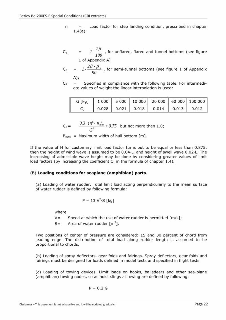
n = Load factor for step landing condition, prescribed in chapter 1.4(a);
C6 = 180
2 - 1
, for unflared, flared and tunnel bottoms (see figure
1 of Appendix A)
C6 = 90
-2 - 1 k
, for semi-tunnel bottoms (see figure 1 of Appendix
A);
C7 = Specified in compliance with the following table. For intermedi-ate values of weight the linear interpolation is used:
G [kg] 1 000 5 000 10 000 20 000 60 000 100 000
C7 0.028 0.021 0.018 0.014 0.013 0.012
C8 = 0.75 + G
B 100.32
6 6max
, but not more then 1.0;
Bmax = Maximum width of hull bottom [m].
If the value of H for customary limit load factor turns out to be equal or less than 0.875, then the height of wind wave is assumed to be 0.04·L, and height of swell wave 0.02·L. The increasing of admissible wave height may be done by considering greater values of limit load factors (by increasing the coefficient C1 in the formula of chapter 1.4).
(B) Loading conditions for seaplane (amphibian) parts.
(a) Loading of water rudder. Total limit load acting perpendicularly to the mean surface of water rudder is defined by following formula:
P = 13·V2·S [kg]
where
V = Speed at which the use of water rudder is permitted [m/s];
S = Area of water rudder [m2].
Two positions of center of pressure are considered: 15 and 30 percent of chord from leading edge. The distribution of total load along rudder length is assumed to be proportional to chords.
(b) Loading of spray-deflectors, gear folds and fairings. Spray-deflectors, gear folds and fairings must be designed for loads defined in model tests and specified in flight tests.
(c) Loading of towing devices. Limit loads on hooks, balladeers and other sea-plane (amphibian) towing nodes, so as hoist slings at towing are defined by following:
P = 0.2·G

Beriev Be‐200ES‐E Special Conditions (CRI extracts)
Disclaimer – This document is not exhaustive and it will be updated gradually. Page 23
Here and after in (B)
G = Maximum take-off weight [kg].
This load acts in vertical plane at 10 up and 20° down and in any direction in horizontal plane, but it lateral component need not to be greater than 0.1·G.
(d) Loading of fastening nods at parking. With seaplane (amphibian) on mooring at anchor or on mooring gear the restraining force acting on airframe nodes is assumed to be
P = 0.7·G
Factor of safety is 2.0. For hoist slings and nonairframe nodes the factor of safety is 3.0.
(e) Loading of main nodes of gear non-use for landing and takeoff. The following loading conditions are considered:
(1) The checking at descending by brake shoe. Simultaneously acting forces on wheel axes of every strut are applied:
- vertically upwards Pz = G,
- in longitudinal direction Px = ±0.4·G.
(2) Turning at parking.
Simultaneously acting forces on wheel axes of every strut are applied:
- vertically upwards Pz = 0.07·G;
- in lateral direction Py = ±0.35·G.
(f) Loading of tail bogey. The following loading conditions are considered:
(1) Simultaneously acting forces on wheel axes of tail bogey are applied:
- vertically upwards Pz = 2·Pt,
- in longitudinal direction Px = ±0.8·Pt.
(2) Simultaneously acting forces on wheel axes of tail bogey are applied:
- vertically upwards Pz = 1.4·Pt;
- in lateral direction Py =±0.7·Pt,
where Pt is assumed to be not greater than Ptp - the load at sea-plane (amphibian) parking. If sea-plane (amphibian) is to be operating on unpaved fields, then all loads on gear unused for landing and takeoff must be increased by 40 percent.
(C) Seaplane (amphibian) dynamic loading.
(a) Seaplane (amphibian) structure must be designed for dynamic action of
hydrodynamic loads at takeoffs and landings on rough water surface.

Beriev Be‐200ES‐E Special Conditions (CRI extracts)
Disclaimer – This document is not exhaustive and it will be updated gradually. Page 24
(b) Calculations must be made for range of wave lengths that in combination with velocity under consideration produce frequencies coinciding with frequencies of first five - six (lowest) elastic modes of structure.
The wave lengths are considered in the range of wave length to its height ratio: l/h3% = 8/30, unless otherwise provided additionally. Several values of velocity must be considered:
for takeoff - from the beginning of gliding to 0.95·VLOF and
for landing - from first touchdown to the end of gliding.
At takeoff the maximum takeoff weight is taken into account, and at landing the maximum landing weight.
The encounter of seaplane (amphibian) with single wave that has maximum limit height h3% max , must be considered, so as the encounter with three - four repeated waves of constant length and height; for repeated waves the value of their height is assumed to be up to 0.75·h3% max (here h3% max - maximum appointed height of wind wave). Duration of motion under consideration is for single wave up to time t > 2·l/V, and for repeated waves - up to t > 6·l/V.
If seaplane (amphibian) has external equipment containers, tanks and other hanged objects, then additional wave lengths must be considered so that the frequency of meeting with them coincides with natural frequencies of those objects on pylons.
And if natural frequencies of those objects are close to airframe frequencies or to frequencies of those objects on pylons, then the elastic vibrations of those objects must be considered additionally.
In the absence of more exact method, the analysis may be divided in two stages:
- the hulls (floats) loads are defined regardless to airframe elasticity;
- the elastic vibrations of sea-plane (amphibian) with hanged objects, arisen from hull (floats) forces, that are calculated at the first stage, are considered.
Factor of safety is 1.5 for a single wave, and 1.3 - for repeated waves.
(c) Results of dynamic loading calculations must be confirmed by special experimental investigations on elastic dynamically similar models of seaplane (amphibian).
1.2 Design weights and centre of gravity positions
(a) Design weights. The water load requirements must be met at each operating weight up to the design landing weight except that, for the takeoff condition prescribed in chapter 1.6, the design water takeoff weight (the maximum weight for water taxi and takeoff run) must be used.
(b) Centre of gravity positions. The critical centres of gravity within the limits for which certification is requested must be considered to reach maximum design loads for each part of the seaplane structure.

Beriev Be‐200ES‐E Special Conditions (CRI extracts)
Disclaimer – This document is not exhaustive and it will be updated gradually. Page 25
(c) The design takeoff weights of amphibians for operation from water are set independently from corresponding weights for operation from ground.
1.3 Application of loads (a) Unless otherwise prescribed, the seaplane as a whole is assumed to be subjected to the loads corresponding to the load factors specified in chapter 1.4.
(b) In applying the loads resulting from the load factors prescribed in chapter 1.4, the loads may be distributed over the hull or main float bottom (in order to avoid excessive local shear loads and bending moments at the location of water load application) using pressures not less than those prescribed in chapter 1.7 (c).
(c) For twin float (twin hull) seaplanes, each float must be treated as an equivalent hull on a fictitious seaplane with a weight equal to one-half the weight of the twin float seaplane.
(d) Except in the takeoff condition of chapter 1.6, aerodynamic lift on the seaplane during the impact is assumed to be 2/3 of the weight of the seaplane and applied in the centre of gravity.
1.4 Hull and main float load factors.
(a) Water reaction load factors nw must be computed in the following manner:
(1) For the step landing case
(2) For the bow and stern landing cases
(b) The following
values are used:
(1) nw = water reaction load factor (that is, the water reaction divided by seaplane weight).
(2) C1= empirical seaplane operations factor equal to 0.00269 except that this factor may not be less than that necessary to obtain the minimum value of step load factor of 2.33.
(3) VS0 = seaplane stalling speed [km/h] with flaps extended in the appropriate landing position and with no slipstream effect.
(4) = angle of dead rise at the longitudinal station at which the hydromechanic load is being determined, in accordance with figure 1 of Appendix A.
(5) G = seaplane design landing weight [kg].
; G ))tan( 3
132
(V C = n
2 S01
w
r + 1
K G ))tan( 2
x
1
32
31
32
(
V C = n2
S01w

Beriev Be‐200ES‐E Special Conditions (CRI extracts)
Disclaimer – This document is not exhaustive and it will be updated gradually. Page 26
(6) K1 = empirical hull station weighing factor, in accordance with figure 2 of Appendix A.
(7) rx = ratio of distance, measured parallel to hull reference axis, from the centre of gravity of the seaplane to the hull longitudinal station at which the hydromechanic load is applied to the radius of gyration in pitch of the seaplane, the hull reference axis being a straight line, in the plane of symmetry, tangential to the keel at the main step.
(c) For a twin float seaplane, because of the effect of flexibility of the attachment of the floats to the seaplane, the factor K1 may be reduced at the bow and stern to 0.8 of the value shown in figure 2 of Appendix A. This reduction applies only to the design of the carry-through and seaplane structure but not to the floats structure itself.
1.5 Hull and main float landing conditions
(a) Symmetrical step, bow, and stern landing. For symmetrical step, bow, and stern landings, the limit water reaction load factors are those computed under chapter 1.4. The following loading conditions are considered:
(1) For symmetrical step landings, the resultant water load must be applied at the keel, through the centre of gravity of loading surface and must be directed perpendicularly to the keel line. The distribution of this load is made upon the forebody bottom upstream the step; angle of dead rise is taken at longitudinal station, where the center of gravity is;
(2) For symmetrical bow landings, the resultant water load must be applied at the keel, one-fifth of the longitudinal distance from the bow to the step, and must be directed perpendicularly to the keel line; and
(3) For symmetrical stern landings, the resultant water load must be applied at the keel, at a point 85 percent of the longitudinal distance from the step to the stern post, and must be directed perpendicularly to the keel line.
(b) Unsymmetrical landing for hull and single float seaplanes. Unsymmetrical step, bow, and stern landing conditions must be investigated. In addition--
(1) The loading for each condition consists of an upward component and a side component equal, respectively, to 0.75 and 0.25·tan() times the resultant load in the corresponding symmetrical landing condition; and
(2) The point of application and direction of the upward component of the load is the same as that in the symmetrical condition, and the point of application of the side component is at the same longitudinal station as the upward component but is directed inward perpendicularly to the plane of symmetry at a point midway between the keel and chine lines.
(c) Unsymmetrical landing; twin float seaplanes. The unsymmetrical loading consists of an upward load at the step of each float of 0.75 and a side load of 0.25·tan() at one float times the step landing load reached under chapter 1.4. The side load is directed inboard, perpendicularly to the plane of symmetry midway between the keel and chine lines of the float, at the same longitudinal station as the upward load. 1.6 Hull and main float takeoff condition.
For the wing and its attachment to the hull or main float--

Beriev Be‐200ES‐E Special Conditions (CRI extracts)
Disclaimer – This document is not exhaustive and it will be updated gradually. Page 27
(a) The aerodynamic wing lift is assumed to be zero; and
(b) A downward inertia load, corresponding to a load factor computed from the following
formula, must be applied:
where
n = inertia load factor;
CTO = empirical seaplane operations factor equal to 0.000895;
VS1 = seaplane stalling speed [km/h] at the design takeoff weight within the flaps extended in the appropriate takeoff position;
= angle of dead rise at the main step [degrees]; and
G = design water takeoff weight in [kg].
1.7 Hull and main float bottom pressures.
(a) General. The hull and main float structure, including frames and bulkheads, stringers, and bottom plating, must be designed under this section.
(b) Local pressures. For the design of the bottom plating and stringers and their attachments to the supporting structure, the following pressure distributions must be applied:
(1) For an unflared bottom, the pressure at the chine is 0.75 times the pressure at the keel, and the pressures between the keel and chine vary linearly, in accordance with figure 3 of Appendix A. The pressure at the keel [kg/m2] is computed as follows:
where
pk = pressure [kg/m2] at the keel;
C2 = 0.437;
K2 = hull (float) station weighing factor, in accordance with figure 2 of Appendix A;
VS1 = seaplane stalling speed [km/h] at the design water takeoff weight with flaps extended in the appropriate takeoff position; and
k = angle of dead rise at keel, in accordance with figure 1 of Appendix A.
G ))tan( 3
132
21
(
V C = n STO
) (tan k
21
S2
2k
V K C = p
Beriev Be‐200ES‐E Special Conditions (CRI extracts)
Disclaimer – This document is not exhaustive and it will be updated gradually. Page 28
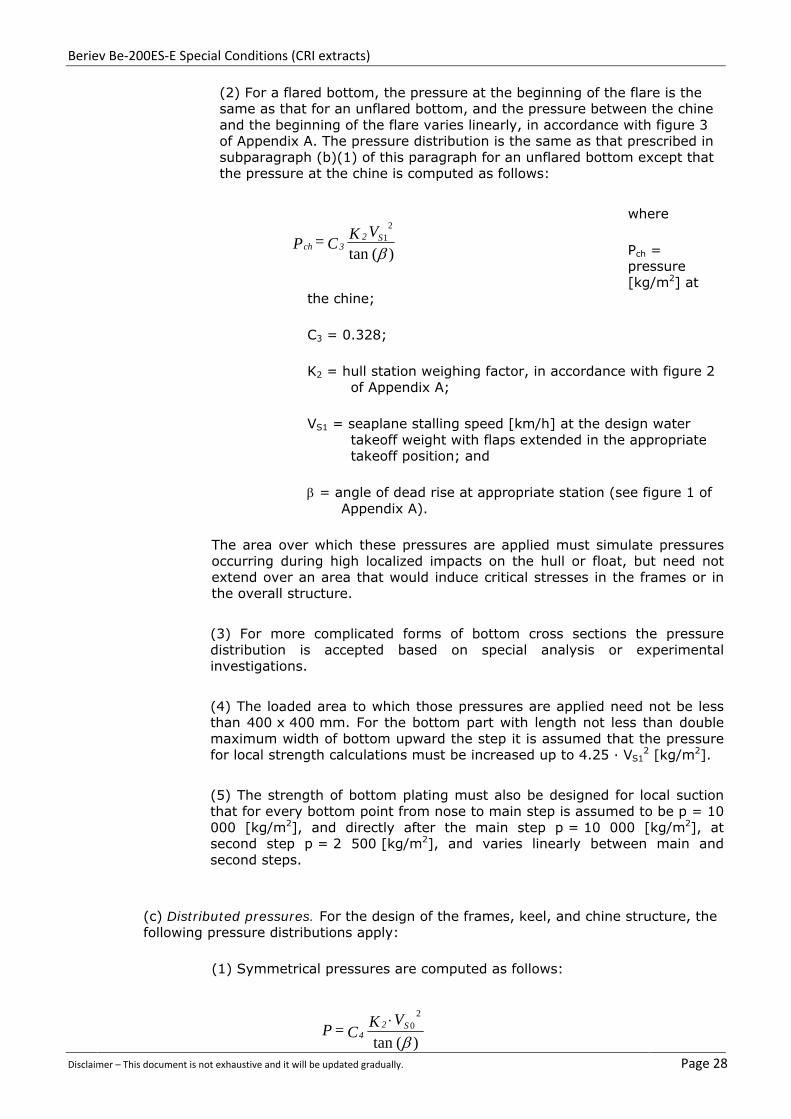
(2) For a flared bottom, the pressure at the beginning of the flare is the same as that for an unflared bottom, and the pressure between the chine and the beginning of the flare varies linearly, in accordance with figure 3 of Appendix A. The pressure distribution is the same as that prescribed in subparagraph (b)(1) of this paragraph for an unflared bottom except that the pressure at the chine is computed as follows:
where
Pch = pressure [kg/m2] at
the chine;
C3 = 0.328;
K2 = hull station weighing factor, in accordance with figure 2 of Appendix A;
VS1 = seaplane stalling speed [km/h] at the design water takeoff weight with flaps extended in the appropriate takeoff position; and
= angle of dead rise at appropriate station (see figure 1 of Appendix A).
The area over which these pressures are applied must simulate pressures occurring during high localized impacts on the hull or float, but need not extend over an area that would induce critical stresses in the frames or in the overall structure.
(3) For more complicated forms of bottom cross sections the pressure distribution is accepted based on special analysis or experimental investigations.
(4) The loaded area to which those pressures are applied need not be less than 400 x 400 mm. For the bottom part with length not less than double maximum width of bottom upward the step it is assumed that the pressure for local strength calculations must be increased up to 4.25 · VS1
2 [kg/m2].
(5) The strength of bottom plating must also be designed for local suction that for every bottom point from nose to main step is assumed to be p = 10 000 [kg/m2], and directly after the main step p = 10 000 [kg/m2], at second step p = 2 500 [kg/m2], and varies linearly between main and second steps.
(c) Distributed pressures. For the design of the frames, keel, and chine structure, the following pressure distributions apply:
(1) Symmetrical pressures are computed as follows:
)(tan
21
S2
3chV K C = P
)(tan
20
S2
4
V K C = P

Beriev Be‐200ES‐E Special Conditions (CRI extracts)
Disclaimer – This document is not exhaustive and it will be updated gradually. Page 29
where P = pressure [kg/m2];
C4 = 0.192;
K2 = hull (float) station weighing factor, determined in accordance with figure 2 of Appendix A;
VS0 = seaplane stalling speed [km/h] with landing flaps extended in the appropriate position and with no slipstream effect; and
= angle of dead rise at appropriate station.
(2) The unsymmetrical pressure distribution consists of the pressures prescribed in subparagraph (c)(1) of this paragraph on one side of the hull or main float centreline and one-half of that pressure on the other side of the hull or main float centreline, in accordance with figure 3 of Appendix A. (3) These pressures are uniform and must be applied simultaneously over the entire hull or main float bottom. The loads obtained must be carried into the sidewall structure of the hull proper, but need not be transmitted in a fore and aft direction as shear and bending loads.
1.8 Auxiliary float loads
(a) General. Auxiliary floats and their attachments and supporting structures must be designed for the conditions prescribed in this section. In the cases specified in paragraphs (b) through (e) of this section, the prescribed water loads may be distributed over the float bottom to avoid excessive local loads, using bottom pressures not less than those prescribed in paragraph (g) of this section.
(b) Step loading. The resultant water load must be applied in the plane of symmetry of the float at a point three-fourths of the distance from the bow to the step and must be perpendicular to the keel. The resultant limit load is computed as follows, except that the value of L need not exceed three times the weight of the displaced water when the float is completely submerged:
where
L = limit load [kg];
C5 =
0.00119;
VS0 = seaplane stalling speed [km/h] with landing flaps extended in the appropriate position and with no slipstream effect;
G = seaplane design landing weight [kg];
s = angle of dead rise at a station ¾ of the distance from the bow to the step, but need not be less than 15 degrees; and
r + 1 )) tan( 2
s
20
32
32
y
S5
(
G V C = L
32

Beriev Be‐200ES‐E Special Conditions (CRI extracts)
Disclaimer – This document is not exhaustive and it will be updated gradually. Page 30
ry = ratio of the lateral distance between the centre of gravity and the plane of symmetry of the float to the radius of gyration in roll.
(c) Bow loading. The resultant limit load must be applied in the plane of symmetry of the float at a point one-fourth of the distance from the bow to the step and must be perpendicular to the tangent to the keel line at that point. The magnitude of the resultant load is that specified in paragraph (b) of this section.
(d) Unsymmetrical step loading. The resultant water load consists of a component equal to 0.75 times the load specified in paragraph (b) of this section and a side component equal to 0.25·tan(S) times the load specified in paragraph (b) of this section. The side load must be applied perpendicularly to the plane of symmetry of the float in direction to and out the float at a point midway between the keel and the chine.
(e) Unsymmetrical bow loading. The resultant water load consists of a component equal to 0.75 times the load specified in paragraph (c) of this section and a side component equal to 0.25·tan(S) times this load. The side load must be applied perpendicularly to the plane of symmetry at a point midway between the keel and the chine.
(f) Immersed float condition. The resultant load must be applied at the centroid of the cross section of the float at a point one-third of the distance from the bow to the stern. The limit load components are as follows:
vertical = ρ g D.
aft = )V (k D 2
C S02
3
2
x
.
side = )V (k D 2
C S02
3
2
y
.
where
ρ = mass density of water [kg s2/m4];
D = volume of float [m3];
Cx = coefficient of drag force, equal to 0.0036;
Cy = coefficient of side force, equal to 0.0029;
K = 0.8, except that lower values may be used if it is shown that the floats are incapable of submerging at a speed of 0.8·VS0 in normal operations;
VS0 = seaplane stalling speed [km/h] with landing flaps extended in the appropriate position and with no slipstream effect; and
g = acceleration due to gravity [m/s2].

Beriev Be‐200ES‐E Special Conditions (CRI extracts)
Disclaimer – This document is not exhaustive and it will be updated gradually. Page 31
(g) Float bottom pressures. The float bottom pressures must be established under Chapter 1.7, except that the value of K2 in the formulae may be taken as 1.0. The angle of dead rise to be used in determining the float bottom pressures is set forth in paragraph (b) of this section. 1.9 Seawing and wing loads at immersion.
Seawing and wing design loads at immersion must be based on applicable test data.
FLOATS AND HULLS 1.10 Main Float Buoyancy
Each main float must have--
(a) A buoyancy of 80 percent in excess of that required to support the maximum weight of the seaplane or amphibian in fresh water; and
(b) Not less than five watertight compartments approximately equal in volume.
1.11 Main Float Design
Each main float must be approved and must meet the requirements of Chapter 1.1.
1.12 Hulls
(a) Each hull must have enough watertight compartments so that, with any two adjacent compartments flooded, the buoyancy of the hull and auxiliary floats (and wheel tires, if used) provides a margin of positive stability great enough to minimize the probability of capsizing in rough, fresh water.
(b) Bulkheads with watertight doors may be used for communication between compartments.
Appendix A:

B
D
Beriev Be‐20
Disclaimer – This
0ES‐E Specia
document is not
al Conditions
exhaustive and i
y
s (CRI extract
t will be updated
Y
Z
y
ts)
d gradually.
Z
Page 332

Beriev Be‐200ES‐E Special Conditions (CRI extracts)
Disclaimer – This document is not exhaustive and it will be updated gradually. Page 33

Beriev Be‐200ES‐E Special Conditions (CRI extracts)
Disclaimer – This document is not exhaustive and it will be updated gradually. Page 34
CRI C-10 – Unsymmetrical Loads on Floats
REQUIREMENTS: JAR 25, Change 14 & OP 25.96.1 effective 19.04.96
AFFECTED PARAGRAPHS: 25.427(b)(3), 25.459
ADVISORY MATERIAL: nil
Floats, their attachment fittings and supporting structure were analyzed by Beriev for the cases specified in para. 25.535 of AR-25 «Auxiliary float loads», namely:
- bow loading (Gfloat);
- step loading (Еfloat);
- unsymmetrical bow loading (Gfloat+Ffloat);
- unsymmetrical step loading (Еfloat+Ffloat);
- immersed float condition.
The calculation of the loads on the float and the substantiation of its strength are provided in the documents approved by IAC AR:
[1]. «Analysis of hydrodynamic loads on the float» (A200.1702.06)
[2]. Summary report № 2 on the results of Be-200 assemblies static tests (status as of 11.12.2003)
Beriev has analyzed the aerodynamic loads on the float in flight loading conditions and in case of a singe gust effecting on the float. The loads comparative results are provided in Table №1.
Comparative table for ultimate loads effecting on the float:
Table №1
Loads during on-water operations
from [1]
Flight loading conditions (aerodynamic loads)
Px, kg Py, kg Pz, kg Px, kg Py, kg Pz, kg
Gfloat -1486 7825 - A’ - 335 -
Efloat - 7965 - A - 344 -
Gfloat+Ffloat -1115 5869 ±1991 D’ - - -
Efloat+Ffloat - 5974 ±1991
Level attitude +vertical tail maneuvering
load
- - ±167
Immersed float
-3582 2655 ±2886
The loads represented in Table №1 demonstrate that the loads on the float in flight loading conditions (including the case of a signe air gust for Level attitude +vertical tail maneuvering load conditions) are significantly less than the loads on the float during on-water operations.
Table № 2 represents the results of the float and wing static tests by the loads effecting on the float (at test-bench) from [2].

Beriev Be‐200ES‐E Special Conditions (CRI extracts)
Disclaimer – This document is not exhaustive and it will be updated gradually. Page 35
Summary report № 2 on results of Be-200 assemblies static tests (status as of 11.12.2003)
Table № 2
№ Assembly
description Test date
Design case
Permanent deformation
after application of
67% Рult.
Real strength in % Рult.
Main test results
46
Wing effected by the loads on the wingtip
float Report №2330
4-9.11.2000
Еfloat None 100% Sufficient structural strength
10-11.11.2000
Еfloat + Ffloat
None 100%
Sufficient structural strength
15.11.2000 Gfloat None
100% Sufficient structural strength
16-18.11.2000
Gfloat + Ffloat
None 100%
Sufficient structural strength
72
Wingtip float tested at the test-
bench
18.01.02 Еfloat None
>100% Sufficient structural strength
24-25.01.02
Gfloat None
>100% Sufficient structural strength
12.02.02 Gfloat + Ffloat
None >100%
Sufficient structural strength
27.02.02 Еfloat + Ffloat
None >100%
Sufficient structural strength
14.03.02
Float bottom
local strength
when effected by cell load
None >150%
Sufficient structural strength

Beriev Be‐200ES‐E Special Conditions (CRI extracts)
Disclaimer – This document is not exhaustive and it will be updated gradually. Page 36
CRI C-15 – Loading of towing devices
REQUIREMENTS: JAR 25, Change 14 & OP 25.96.1 effective 19.04.96
AFFECTED PARAGRAPHS: 25.509
ADVISORY MATERIAL: nil
Bе-200ES-E aircraft is equipped with special devices intended for cable-towing when on ground and when pulled from the water (nose cleats, stern hook, fittings on main LG struts).
The compliance with the requirements to hydroplanes structural strength specified in «Loading of hydroplane parts» МОС25.521(с) SC C-6 is provided in the following documents approved by IAC AR:
«Summary of loads calculation results for the aircraft assemblies, Part 2» (Report № 67).
2. «Summary report №2 on the static test results of Bе-200 assemblies as of 11.12.2003» ( № 2si)
3. AFM Book 1 «Бе-200ES amphibious aircraft. Flight Manual. Subsection 4.5 Aircraft waterborne operations»
1.1 Operational limitations
For the towing period an aircraft technician, admitted for the operations with the braking system, must be present in the cockpit. When putting the aircraft afloat, the flight crew must be in the cockpit.
Operational limitations:
– Angle of taxiway slope, degrees, maximum 3
– Angle of ramp slope, degrees, maximum 7
– Wind wave limit height when putting the aircraft afloat, m, maximum 0.6
– Ripple wave limit height when putting the aircraft afloat, m, maximum 0.3
– Wind absolute speed for taxiing and towing, m/sec, maximum
• on ground airfield 25
• on water airdrome 12
– Speed for the aircraft towing on ground, km/h, maximum 5
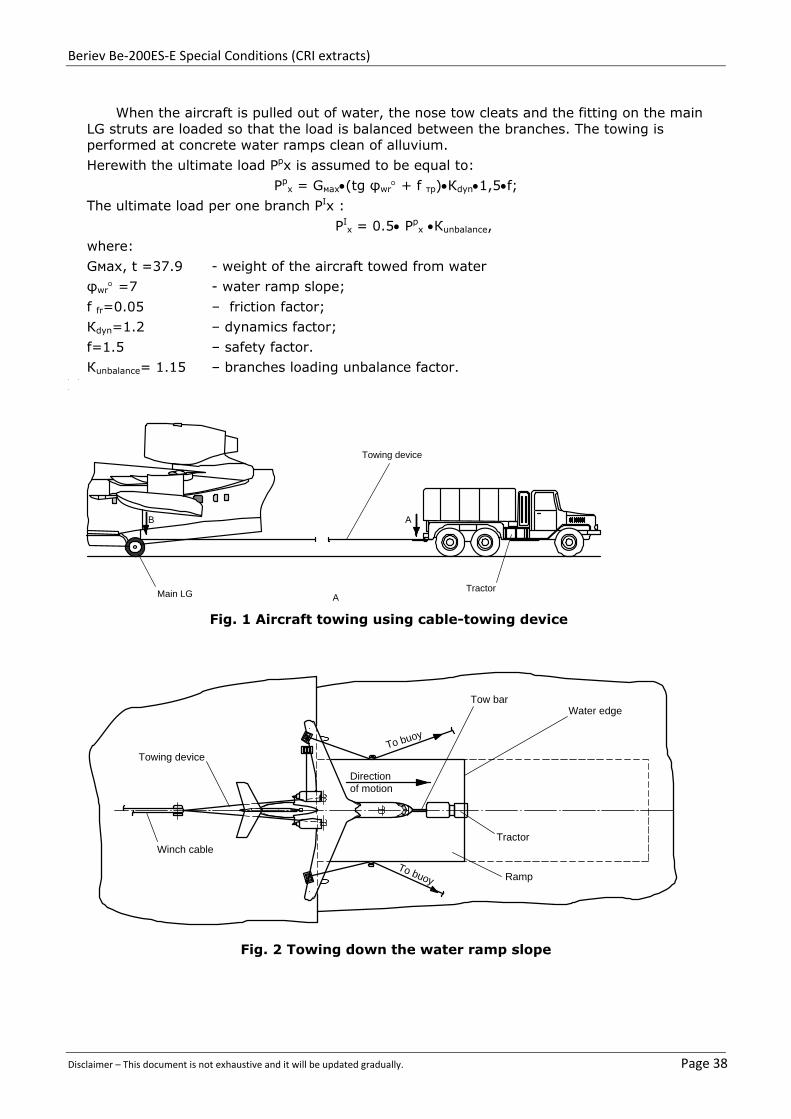
1.2 On-ground towing using cable-towing device
Aircraft towing with tail forward is generally used for the aircraft motion on unpaved surface after its rolling from the runway.
Aircraft towing with the tail forward is performed by a tow truck by means of a towing device attached to the main LG legs. The nose LG is used for attachment of a tow bar intended for the aircraft control.
The aircraft towing using cable-towing device is shown in Fig.1.
1.3 Putting afloat
1.3.1 Towing down along the ramp slope.
The towing down along the ramp slope is shown in Fig.2
1.3.2 Aircraft putting afloat
The following is applied for the aircraft putting afloat:
– three winches with the force of 3.2 t;
– one winch with the force of 7.5 t;
– motor boat;
– cable-towing device;
– cables;
– two buoys (two bottom anchors).

Beriev Be‐200ES‐E Special Conditions (CRI extracts)
Disclaimer – This document is not exhaustive and it will be updated gradually. Page 37
Putting the aircraft afloat is shown in Fig.3
1.4 Towing on water towards the ramp
The aircraft is towed on water by a motor boat attached to the nose cleats (with the nose forward) or to a stern hook (with the tail forward). The aircraft towing on water is shown in Fig. 4
The following equipment is used for the aircraft towing on water towards the water-ramp:
– three winches with the force of 3.2 t;
– one winch with the force of 7.5 t;
– motor boat;
– cables;
– two buoys (two bottom anchors).
In adverse weather conditions, to prevent the aircraft driftage to the shore, an auxiliary motor boat cable is attached to the stern hook. The aircraft towing on the water surface towards the ramp is shown in Fig. 5.
In compliance with МОС25.521(B)(с) the ultimate load on the stern hook in case of the aircraft towing in the open sea is defined as follows:
Pp = 0,2GTO·f; where
GTO· , kg - aircraft maximum take-off weight
f = 1.5 – safety factor.
The ultimate load on the forward cleat in case of towing by a waterborne vehicle with the draught of < 0.5GTO is defined as follows:
Pp = 0.1GTO·f; where
GTO· , kg - maximum take-off weight
f = 1.5 – safety factor.
Direction of load on the hook and the cleat:
The load is effective in the vertical plane from 10 upwards to 20 downwards, and in any direction in the horizontal plane, but its side component exceeding 0.1G is not accounted for.
The loads distribution on the stern hook and the nose towing cleat is shown in [1].
1.5 Exit from water: towing upward the water ramp
The aircraft is towed using a winch with the force of 7.5 t and two cables attached to its nose hooks.
A tow-bar is attached to the nose LG to enable the nose wheel steering. The tow-bar is controlled by two persons using lines.
The aircraft towing upward the water ramp is shown in Fig.6
Beriev Be‐200ES‐E Special Conditions (CRI extracts)
Disclaimer – This document is not exhaustive and it will be updated gradually. Page 38
When the aircraft is pulled out of water, the nose tow cleats and the fitting on the main LG struts are loaded so that the load is balanced between the branches. The towing is performed at concrete water ramps clean of alluvium.
Herewith the ultimate load Ppx is assumed to be equal to:
Ppx = Gмах(tg φwr + f тр)Кdyn1,5f;
The ultimate load per one branch PIx :
PIx = 0.5 Pp
x Кunbalance,
where:
Gмах, t =37.9 - weight of the aircraft towed from water
φwr =7 - water ramp slope;
f fr=0.05 – friction factor;
Кdyn=1.2 – dynamics factor;
f=1.5 – safety factor.
Кunbalance= 1.15 – branches loading unbalance factor.
Fig. 1 Aircraft towing using cable-towing device
Fig. 2 Towing down the water ramp slope
A
A
B
Towing device
TractorMain LG
RampTo buoy
Winch cable
Directionof motion
Tow barWater edge
Towing deviceTo buoy
Tractor

Beriev Be‐200ES‐E Special Conditions (CRI extracts)
Disclaimer – This document is not exhaustive and it will be updated gradually. Page 39
Fig. 3 Putting the aircraft afloat.
C
To
buoy
From
buo
y

Beriev Be‐200ES‐E Special Conditions (CRI extracts)
Disclaimer – This document is not exhaustive and it will be updated gradually. Page 40
Fig. 4 Aircraft towing on water

Beriev Be‐200ES‐E Special Conditions (CRI extracts)
Disclaimer – This document is not exhaustive and it will be updated gradually. Page 41
Fig. 5 Aircraft towing on water towards the ramp
Adapter to auxiliary winch
Adapter to auxiliary winch
Adapter to aft hook
Signal buoy
to buoy
from buoy
from
buo
yBoat-tractor
Directionof motion
Cable of sideauxiliary winch
Cable of centralauxiliary winch

B
D
Beriev Be‐20
Disclaimer – This
Summ
№ Asse
descr
0ES‐E Specia
document is not
mary report
embly ription
al Conditions
exhaustive and i
Fig. 6 Airc
№ 2 on re
Test date
s (CRI extract
t will be updated
craft towin
sults of Be-
Design
ts)
d gradually.
ng upward
-200 assem
case
d the wate
mblies static
Permanedeformat
er ramp.
c tests (as o
ent ion
Rstre
of 11.12.20
Table №1
Real ength in
Page 4
03)
Main test
42

Beriev Be‐200ES‐E Special Conditions (CRI extracts)
Disclaimer – This document is not exhaustive and it will be updated gradually. Page 43
after application of 67% Рult.
% of Рult. results
41 Stern hook
28-30.10.200
0
Load along the aircraft centerline at 200 to horizon
None 100%
Sufficicent
structural strength
24-27.02.200
1
Load in horizontal plane
None
100%
Sufficicent structural strength
64 Nose towing
device
26.07.01 Aircraft pulling out of water
None
>100%
Sufficicent structural strength
27-30.07.01
Towing on water
None
>100%
Sufficicent structural strength
31.07.01
Motor boat tie-down to enable boarding and
disembarkation
None
>100%
Sufficicent structural strength
83 Nose towing
device 20.09-
04.10.02 Operation

Beriev Be‐200ES‐E Special Conditions (CRI extracts)
Disclaimer – This document is not exhaustive and it will be updated gradually. Page 44
CRI C-16 – Loading of attachment fittings of anchored aircraft
REQUIREMENTS: JAR 25, Change 14 & OP 25.96.1 effective 19.04.96
AFFECTED PARAGRAPHS: 25.519(c)
ADVISORY MATERIAL: nil
Be-200ES-E amphibious aircraft is fitted with a special system which enables the aircraft tie-down in the sea (at a water aerodrome). The possibility of the aircraft tie-down to a bottom anchor by means of cables attached to the aircraft nose cleats is also provided.
The substantiation of compliance with the hydroplane strength requirements stated in «Loading of attachment fittings at parking area» SC C-7 (Supplement to МОС25.521(B)(d)) is provided in the following documents approved by IAC AR:
[1.] «Analysis of external loads on the aircraft assemblies» (Report № 67)
[2.] «Summary report №2 on the results of Be-200 assemblies static tests as of 11.12.2003» (№ 2si)
[3.] AFM Book 1«Bе-200ES amphibious aircraft. Flight Manual. Subsection 4.5 Aircraft waterborne operations»
Beriev reviewed the following loading cases of the aircraft tow cleats during aircraft tie-down:
1. Securing of amphibious aircraft to an anchor (buoy) (see Fig.1, Fig.2)
Two variants of the nose tow cleats loading were reviewed for the case of the aircraft securing to the buoy.
1.1 Tie-down using one cleat.
Tie-down using one cleat is applied at the water areas with the wave height not exceeding Hwh 1.2 m at the wing speed V wind 14 m/sec.
1.2 Tie-down using two cleats.
Tie-down using two cleats is applied at the water areas, where the wave height does not exceed Hwh 2 m at the wind speed V wind 18 m/sec.
For the aircraft securing to an anchor, a kapron anchor cable (10 mm) is attached to the aircraft nose cleat (GOST 10293-77).
In accordance with SC С-7 of Bе-200ES CB («Loading of attachment fitting at parking area» Supplement to МОС25.521(B)(d)) Cable breaking tension (for one branch) is defined as follows:
Рр = 1630f = 16301.5 = 2445 kg;
Note: Compared to A/C attachment area ultimate load capability, proven by static test, (~6900 kg) see doc ref [2], the cable remains a weak point that prevents A/C structure from damage in case of any cables overloading during operations.
Table № 1 represents abstracts from «Summary report № 2 on the results of Be-200 assemblies static tests...».

Beriev Be‐200ES‐E Special Conditions (CRI extracts)
Disclaimer – This document is not exhaustive and it will be updated gradually. Page 45
Fig.1 Securing of amphibious aircraft to an anchor (buoy).
Êàòåð áóêñèðîâùèê
Áóêñèðîâî÷íûé êàíàò
ßêîðíûé óñ
Áî÷êà
Ëîäêà íàäóâíàÿ
Ïåðåõîäíèê ê êàíàòóáóêñèðîâî÷íîãî êàòåðà
Áóêñèðîâî÷íûé êàíàò
Êàòåð âñïîìîãàòåëüíûé
Towing motor boat
Tow cable
Anchor line
Buoy
Inflatable boat
Adapter for the towing boat
Tow cable
Auxiliary motor boat

B
D
Beriev Be‐20
Disclaimer – This
Summ
0ES‐E Specia
document is not
mary report
Hook of the
position
al Conditions
exhaustive and i
Fig.
№ 2 on th
e nose towin
s (CRI extract
t will be updated
.2 Aircraft
e results of
ng
ts)
d gradually.
t securing
f Be-200 as
Ancho
Hook stow
to an anc
ssemblies s
Bu
r line
wed position
hor.
static tests
oy
Fixed anch
n
(as of 11.
Table № 1
hor
Page 4
12.2003)
1
46

Beriev Be‐200ES‐E Special Conditions (CRI extracts)
Disclaimer – This document is not exhaustive and it will be updated gradually. Page 47
№ Assembly
descriptioon
Test date
Design case
Permanent deformation
after application of 67% Рult.
Real strength in % of Рult.
Main test
results
64 Nose towing
device
26.07.01 Aircraft pulling out of water
None >100% Sufficientsstructural strength
27-30.07.01
Aircraft towing on water
None
>100%
Sufficientsstructural strength
31.07.01
Motor boat tie-down to enable boarding and
disembarkation
None >100%
Sufficientsstructural strength

Beriev Be‐200ES‐E Special Conditions (CRI extracts)
Disclaimer – This document is not exhaustive and it will be updated gradually. Page 48
CRI C-17 – Loads on water scooping system and water rudder
REQUIREMENTS: JAR 25, Change 14 & OP 25.96.1 effective 19.04.96
AFFECTED PARAGRAPHS: 25.459
ADVISORY MATERIAL: nil
Section «Water landing loads» of Be-200ES Certification Basis contains the requirements 25.521 and the Special Conditions С-5 (Water rudder loading), С-8 (Loads on water scooping system elements).
The substantiation of the compliance with the requirements to the hydroplanes strength related to “Load on the water scooping system and water rudder” is provided in the following documents approved by IAC AR:
[1] «Summary of the calculation results of loads on the aircraft assemblies. Part 2». (Report №67)
[2]. «Summary report №2 on the results of Be-200 assemblies static tests as of 11.12.2003». (№2si) (Water rudder and water scooping device).
[3] AFM, Book 1 «Bе-200ES amphibious aircraft. Flight Manual. Section Aircraft on-water operation»
[4]. AMM (Maintenance Manual) Section 027.21.0 Water rudder control. Description and operation. Troubleshooting.
Water scooping device.
Be-200ES-E amphibious aircraft is fitted with a water scooping system which is designed for the water scooping and dropping, and with a water rudder which is intended to control the aircraft motion on water.
The water scoops serve for filling the water tank while skimming on the water surface. Behind the step there are two water scoops.
The following controls are available in the cockpit in order to control the water scooping system:
– overhead panel;
– aircraft control sticks (the extension and retraction of the water scoops is performed by means of a trigger arranged on the aircraft control stick);
– side consoles.
Water scoopin and dropping system is monitored by the crew using the following:
– MMD electronic indicator (Master monitor Display);
– Indicators located on the overhead panel and instrument panel shield.
The instructions of SC С-8 to МОС 25.521 were applied to calculate the loads.
The determination of the loads on the water scooping device is explained in [1].
Water rudder. The water rudder serves to control the aircraft motion on water.
During the aircraft motion on water the water rudder is controlled from any foot pedals couple by means of their displacement. The pedals displacement is transmitted by FBW transducers.
Two servos operate in response to the transducers signals and move the rigid control linkage to input links of the two rudder actuators. The rudder actuators deflect the water rudder by means of mechanical linkage.
Ahead of the servo input links there area spring-loaded rods. The spring-loaded rods are intended to protect the output links of the servos from loading when afloat or anchored (with hydraulic systems off) due to the waves or wind effect.
Water rudder position indication.

Beriev Be‐200ES‐E Special Conditions (CRI extracts)
Disclaimer – This document is not exhaustive and it will be updated gradually. Page 49
The water rudder position is indicated on the cockpit display on «УПР» (CONTROL) page. Should the water rudder control system be disengaged, its position will also be indicated (an index at «ВР» (water rudder) scale will be lit in white). The water rudder scale will be indicated on «УПР» (CONTROL) page under the following conditions:
- switch light «МОРЕ» (SEA) or «ЗАПОЛН» (FILLED) is depressed;
- FBW system is activated.
During approach to landing, if the water rudder is disengaged and deflected from the neutral to the angle exceeding 2º, light indicators «НЕ ГОТОВ» (NOT READY) start blinking, and the following message appears on the «НЕ ГОТОВ» (NOT READY) page: «НЕТ НЕЙТРАЛИ ВОДОРУЛЯ. ПОСАДКА НА СУШУ» (WATER RUDDER IS NOT IN LINE WITH THE NEUTRAL. LANDING ON GROUND), provided that the switch lights «МОРЕ» (SEA) or «ЗАПОЛН» (FILLED) were depressed.
AMM 027.21.0 provides a caution for the crew which inhibits water landing in case of failures or faults in the functional systems (hydraulic system, aircraft control system, electrical power supply system (EPSS), power plant).
During the take-off run as soon as the aircraft achieves the speed exceeding 50 km/h the water rudder control is automatically disengaged (that is displayed on MMD on «УПР» (CONTROL) page) and all the elements of the control system as well as the water rudder are set by a centering spring-loaded rod to a neutral position.
Should the water rudder fail to be automatically disengaged at the speed of 50 km/h, the master warning light comes on, and «gong» signal sounds, while the annunciation page of MMD gives the instruction «ВОДОРУЛЬ ОТКЛЮЧИ» (DISENGAGE WATER RUDDER) accompanied by the same aural message.
At the speed V≈150 km/h the water rudder control system gets fully disengaged.
In case of the water rudder control failure, two switch lights are lit on the FBW control panel and the water rudder is set to the neutral position by a centering spring-loaded rod. The index at the water rudder scale changes its color to amber and indicates the real water rudder position.
The main means for aircraft maneuvering during water operations is differential engine thrust of the LH and RH engine. Therefore the water rudder control failure is not critical.
Water rudder structure. The water rudder structure is represented in Fig. 1. Following are the main elements of the
water rudder: main frame, skins (bottom, deck and side ones), leading edge and hydrofoil portion.
The skins are riveted to the main frame. The removable leading edge made of two sheets is attached to the main frame by means of bolts and anchor nuts.
The water rudder hydrofoil portion is made of a plate, attached to the main frame by means of bolts. This type of attachment enables to change the hydrofoil, should it be damaged due to concrete runway touch.

Beriev Be‐200ES‐E Special Conditions (CRI extracts)
Disclaimer – This document is not exhaustive and it will be updated gradually. Page 50
Fig. 1 Water rudder.
The distributed hydrodynamic load, acting along the normal towards the hydrofoil chord, was defined using an equation from SC С-5 (Supplement to МОС25.521(B)(a)) «Water rudder loading»).
Hereinafter are the abstracts from the document [2]:
SUMMARY REPORT № 2
Âåðõíÿÿ îïîðàâîäîðóëÿ
Ñúåìíàÿ êðûøêàâîäîðóëÿ
Ðû÷àãóïðàâëåíèÿ
Íèæíÿÿ îïîðàâîäîðóëÿ
Âòóëêà
Ïåðî âîäîðóëÿ
Íîñîêâîäîðóëÿ
Ñëèâíàÿïðîáêà
Îñü âðàùåíèÿâîäîðóëÿ
Ñòð. ¹ 17
Ñòð. ¹ 19
Bushing
Water rudder
upper support
Water rudder
removable cover Control
lever Water rudder axle of
rotation
Water
rudder
lower Water rudder leading
edge
Water rudder hydrofoil
portion
Str. # 17
Str. # 19

Beriev Be‐200ES‐E Special Conditions (CRI extracts)
Disclaimer – This document is not exhaustive and it will be updated gradually. Page 51
on Be-200 assemblies static tests results as of 11.12.2003 (water rudder and water scooping device).
№ Description Test date Design case
Permanent deformation
after application of 67% Рult
Real strength in
% Рult.
Main test results
50
Water rudder.Repor
t №2339
29-30.11.200
0
Local strength due to
hydrodynamic load
No permanentdeformation
100% Sufficient structural strength
16-25.01.200
1
Deflected to 350 No permanent deformation
100% Sufficient structural strength
Water rudder
control.
Report №2339
10.02.2001
РА86-РП100 No permanent deformation
100% Sufficient structural strength
10.02.2001
РА86-ЦПр1 (WR) No permanent deformation
100% Sufficient structural strength
58
Water scoop
23-24.05.200
1
Pressure in the water scoop
No permanent deformation
100% Sufficient structural strength
21.06.2001
Moment due tohydrodynamic forces at thewater scoopextension
No permanent deformation 100%
Sufficient structural strength
Water scoop
18.06.2001
Hydrodynamic load and momentdue to the frictionforces in thewater scoop
No permanent deformation 100%
Sufficient structural strength
26.06.2001
Water scoopingwhile skimming
No permanent deformation
100% Sufficient structural strength
Beriev Be‐200ES‐E Special Conditions (CRI extracts)
Disclaimer – This document is not exhaustive and it will be updated gradually. Page 52
CRI D-08 – Hydraulic fluid overheat
REQUIREMENTS: JAR 25 Change 14
AFFECTED PARAGRAPHS: JAR 25.783, 25. 1435, CS 25.863, 25.1183, 25.1185, 25.1189 and 25.1322;
ADVISORY MATERIAL: ACJ 25.1435 (a) (4)
JAR 25.1435 Change 14 requires in sub par.(a) (8) and (a) (9) that:
“ (8) Each hydraulic pump must be designed and installed so that loss of hydraulic fluid to the pump cannot create a hazard that might prevent continued safe flight and landing (See ACJ 25.1435 (a) (8).)
(9) The system must be designed to avoid hazard to the aeroplane arising from the effects of abnormally high temperatures which may occur in certain parts of the system under fault conditions (See ACJ 25.1435 (a) (4).) “
Such requirements are different from AP 25,.1435 (b) (4) which does not explicitly consider fault conditions :
( Each hydraulic system must ) :
“(4) Meet the applicable requirements of CS 25.863, 25.1183, 25.1185 and 25.1189 if a flammable fluid is used “
Also, ACJ 25.1435 (a) (4) specifies :
It’s recommended that, in achieving compliance with this requirement, reliance should not be placed upon a simple pressure relief device. Experience gained from hydraulic systems in which the pump has failed to off-load and therefore delivered maximum flow at maximum temperature, shows that the resultant temperature rise across the pressure reducing valve can produce fluid degradation and a potentially serious fire hazard, depending on the type of fluid being used. This may also affect the integrity of items such as joints, seals and flexible hoses
The .Be 200 E & ESE includes 3 systems HS1 to HS 3, power driven either by engine driven pump(s) on HS1 & HS2 or by an electrical driven pump on HS3, which can be also powered in emergency by the emergency turbo pump. All return lines are circulating in fuel tank areas of both wings, and their respective temperature is lowered by an individual heat exchanger (fuel to hydraulic), which is by passed by opening of a thermal control valve installed in parallel, as long as the hydraulic temperature is below 70°C . With such a design, the hydraulic fluid temperature has to remain below the fuel self ignition , otherwise any hydraulic leak on this area would allow inflammation of fuel vapour in the tank and generate fire.
The same consequences will occur if the pump rate control device fails at max. pressure delivery and fluid gets heat from circulation through the pressure relief valve. In particular long exposure ground run or flight at low level, in warm atmosphere could lead to this situation after this same single failure happened.
Temperature is measured by a probe installed on the hydraulic tank (except for HS3, not having such a detection, see note 2 below ) and the information is compared to a threshold (90 °C) beyond which a “yellow” (to become Amber from JAR 25.1322) visual annunciation+ aural message is provided to the Crew.
The typical overheat conditions could result of heat exchanger internal leakage, by pass valve failed opened or hydraulic pump control failed at max. pressure.
The problem is the Crew has no other alternative offered other than command depressurization of the related system from control on Overhead panel and land as soon as possible but if the overheat source persists (which would happen if it’s outside the pump area) , temperature could reach the above critical value before landing.., so, under a leakage in the tank area (2nd failure) a catastrophic fire could occur. This would not be compliant with JAR 25.1435 (a) (9), see above.

Beriev Be‐200ES‐E Special Conditions (CRI extracts)
Disclaimer – This document is not exhaustive and it will be updated gradually. Page 53
Note 1: Fire shut off valve operation to close, which gives an acceptable means to comply with 25.1435 (a) (8) is not applicable in case of detected high temperature as it’s only obtained through activation of engine fire handle and in the case of HS2, hydraulically powered from 2 EDPs each driven by a separate engine, it would lead to both engines shut down.
Note 2: HS3 does not have this thermal protection, which from our understanding , results from the following reasons:
a) the system being dedicated to Flight Controls only, most of its equipment and tubing is located in the wings, empennage or vertical fin, which gives a significant cooling effect from forced convection with the air around
b) it has its own heat exchanger, by pass valve and tubing in the right wing, very close to the HS2 one , so in case it gets heated by an internal malfunction, the heat soak will be also seen by HS2, which will be detected, so that Crew can depressurize it and thus reduce the heat amount transferred to adjacent fuel.

Beriev Be‐200ES‐E Special Conditions (CRI extracts)
Disclaimer – This document is not exhaustive and it will be updated gradually. Page 54
CRI E-05 – Falling and blowing snow
REQUIREMENTS:
AFFECTED PARAGRAPHS: JAR 25.1093(b)
ADVISORY MATERIAL: nil
The EASA team recognizes the relevancy of the requirement FAR 25.1093(b)(1)(ii) (Amdt. 25-72) and therefore proposes the following Special Condition.
Amend CS 25.1093 “Air intake system de-icing and anti-icing provisions” by addition of section 25.1093(b)(1)(ii) as follows:
(b) Turbine engines
(1) Each turbine engine must operate throughout the flight power range of the engine (including idling), without the accumulation of ice on the engine, inlet system components, or airframe components that would adversely affect engine operation or cause a serious loss of power or thrust (see ACJ 25.1093(b).)-
(i) Under the icing conditions specified in Appendix C.
(ii) In falling and blowing snow within the limitations established for the aeroplane for such operation."
Furthermore, as in past and current programs, the EASA team considers the interpretative material attached in Appendix to this CRI as acceptable means of compliance for the above special condition
- Appendix -
Interpretative Material and
Acceptable Means of Compliance
Falling and blowing snow is a weather condition, which needs to be considered for the powerplants and essential Auxiliary Power Units (APUs) of transport category aeroplanes. Although snow conditions can be encountered on the ground or in flight, there is little evidence that snow can cause adverse effects in flight on turbojet and turbofan engines with traditional pitot style inlets where protection against icing conditions is provided. However, service history has shown that inflight snow (and mixed phase) conditions have caused power interruptions on some turbine engines and APUs with inlets that incorporate plenum chambers, reverse flow, or particle separating design features.
For turbojet and turbofan engines with traditional pitot (straight duct) type inlets, icing conditions are generally regarded as a more critical case than falling and blowing snow. For these types of inlet, compliance with the icing requirements will be accepted in lieu of any specific snow testing or analysis.
For non-pitot inlet types, demonstration of compliance with the falling and blowing snow

Beriev Be‐200ES‐E Special Conditions (CRI extracts)
Disclaimer – This document is not exhaustive and it will be updated gradually. Page 55
ground conditions should be conducted by tests and/or analysis. If acceptable powerplant operation can be shown in the following conditions, no takeoff restriction on the operation of the aeroplane in snow will be necessary.
a. Visibility: 0.4 Km or less as limited by snow, provided this low visibility is only due to falling snow (i.e. no fog). This condition corresponds approximately to 1 g/m3.
b. Temperatures: -3°C to +2°C for wet (sticky) snow and -9°C to -2°C for dry snow, unless other temperatures are found to be critical (e.g. where dry snow at a lower temperature could cause runback ice where it contacts a heated surface). c. Blowing snow: Where tests are conducted, the effects of blowing snow may be simulated by taxiing the aircraft at 15 to 25 kts, or by using another aircraft to blow snow over the test powerplant. This condition corresponds approximately to 3g/m3. d. Duration: It must be shown that there is no accumulation of snow or slush in the engine, inlet system or on airframe components, which would adversely affect engine operation during any intended ground operation. Compliance evidence should consider a duration which corresponds to the achievement of a steady state condition of accretion and (possible) shedding. Any snow shedding should be acceptable to the engine.
e. Operation: The methods for evaluating the effects of snow on the powerplant should be agreed by the Authority. All types of operation likely to be used on the ground should be considered for the test (or analysis). This should include prolonged idling and power transients consistent with taxiing and other ground manoeuvring conditions. Where any accumulation does occur, the engine should be run up to full power, to simulate takeoff conditions and demonstrate that no hazardous shedding of snow or slush occurs. Adequate means should be used to determine the presence of any hazardous snow accumulation. f. For in-flight snow (and mixed phase) conditions, some non-pitot type inlets with reverse flow particle separators have been found to accumulate snow/ice in the pocket lip (sometimes referred to as the “birdcatcher” section) just below the splitter which divides the engine compressor from the inlet bypass duct. Eventually, the buildup of snow in the pocket (which can melt and refreeze into ice) either spans across to the compressor inlet side of the splitter lip or, the snow/ice buildup is released from the pocket and breaks up whereupon some of the ice pieces can be reingested into the compressor side of the inlet. The ingestion of this snow/ice has caused momentary or permanent flameouts and in some cases, foreign object damage to the compressor. Some airframe manufacturers have tried to correct this condition by increasing the amount and/or frequency of applied thermal heat used around the pocket, splitter, and bypass sections of the inlet. However, short of modifying the engine ice protection systems to the point of operating fully evaporative, these fixes have mostly failed to achieve acceptable results. Airplanes with turbine engine or essential APU inlets which have plenum chambers, screens, particle separators, variable geometry, or any other feature (such as an oil cooler) which may provide a hazardous accumulation site for snow should be qualitatively

Beriev Be‐200ES‐E Special Conditions (CRI extracts)
Disclaimer – This document is not exhaustive and it will be updated gradually. Page 56
evaluated for in-flight snow conditions. The qualitative assessment should include: 1) a visual review of the installed engine and inlet (or drawings) to identify potential snow accumulation sites 2) review of the engine and engine inlet ice protection systems to determine if the systems were designed to run wet, fully evaporative, or just de-ice during icing conditions? 3) unless the inlet ice protection means (e.g. thermal blanket, compressor bleed air, hot oil) operates in a fully evaporative state in and around potential inlet accumulation sites, inlet designs with reverse flow pockets exposed directly to in-flight snow ingestion should be avoided."

Beriev Be‐200ES‐E Special Conditions (CRI extracts)
Disclaimer – This document is not exhaustive and it will be updated gradually. Page 57
CRI F-11 – Marine Equipment
REQUIREMENTS:
AFFECTED PARAGRAPHS: 25.1411, IAC AR special condition CTY/F-4
ADVISORY MATERIAL: nil
1. The marine equipment shall: a. comply with applicable operational requirements b. not interfere, at any time with the A/C systems
2. Stowage provisions for required marine equipment must be furnished and must: a. Be arranged so that the equipment is directly accessible and its location is obvious;
and b. Protect the marine equipment from inadvertent damage.
3. Means must be provided to prevent each item of mass from becoming a hazard by shifting under the appropriate maximum load factors corresponding to the specified flight, ground and water load conditions, and to the emergency landing conditions of JAR 25.561(b).
4. The aircraft shall be provided with safety devices protecting the aircraft structure against non-ultimate loads during aircraft anchoring using bottom or floating anchors.
5. The marine equipment shall include at least the following: a. binoculars providing not less than x-6 magnification for water surface survey prior
to take-off b. towing rope heaving in, and pushing-off of submerged objects c. safety belt, to secure the crew, when marine equipment are operated
6. Brackets for attachment of safety belts shall be installed near each exit (door, hatch) used for activities involving the marine equipment.

Beriev Be‐200ES‐E Special Conditions (CRI extracts)
Disclaimer – This document is not exhaustive and it will be updated gradually. Page 58
CRI F-12 – Rigid Light
REQUIREMENTS:
AFFECTED PARAGRAPHS: FAR 25.1399
ADVISORY MATERIAL: nil
Riding light.
(a) Each riding light required for a seaplane or amphibian must be installed so that it can—
(1) Show a white light for at least 2 nautical miles at night under clear atmospheric conditions; and
(2) Show the maximum unbroken light practicable when the airplane is moored or drifting on the water.

Beriev Be‐200ES‐E Special Conditions (CRI extracts)
Disclaimer – This document is not exhaustive and it will be updated gradually. Page 59
CRI F-13 – Fire Fighting Operations
REQUIREMENTS: AIC AR Aviation Regulations 25 (1994), JAR 25 Change 14, Transport Canada AC525-012
AFFECTED PARAGRAPHS: IR 21A.23
ADVISORY MATERIAL: nil
1 Performance The performance requirements shall be as specified in JAR25 Change 14. Alternatively the minimum performance requirements below are an acceptable means of compliance.
2 Changes to Performance Standards
The performance standards will be those of JAR25 section 25.101 to 25.125 inclusive, and 25.1581(g), with the exceptions listed hereunder and the addition of the climb requirements given in paragraphs 3 and 5:
25.101 (f) Reference to take-off flight paths is not applicable.
25.101 (g) References to 25.119 and 25.121(d) are not applicable.
25.105 (a) References to take-off path described in 25.111, take-off run are not applicable.
25.107 (c) Reference to 25.121(b) is not applicable.
25.107 (c)(2) Reference to 25.111(c)(2) is not applicable.
25.107 (d) Not applicable.
25.107 (e)(1)(iii)
Not applicable.
In lieu of this requirement substitute: VR may not be less than 1.1 V
S.
25.107 (e)(1)(iv)
Not applicable.
25.107 (e)(2) Reference to one-engine-inoperative is not applicable.
25.107 (e)(3) Not applicable.
25.107 (f) Not applicable.
25.109 (a)(1) Not applicable.
25.109 (d) Not applicable.
25.111 Not applicable
25.113 (a)(1) Not applicable.
25.113 (a)(2) Reference to 25.111 is not applicable.
25.113 (b) Not applicable.
25.115 Not applicable.
25.117 References to 25.119 and 25.121 are not applicable.
25.119 Not applicable. See paragraph 5(e).
25.121 Not applicable. See paragraph 3 and 5(a), (b), (c).
25.123 Not applicable. See paragraph 5(d).

Beriev Be‐200ES‐E Special Conditions (CRI extracts)
Disclaimer – This document is not exhaustive and it will be updated gradually. Page 60
25.125(f) Not applicable. In lieu of this requirement a one-engine-inoperative landing distance may be established and presented in the Aeroplane Flight Manual (AFM).
25.1581(g) Not applicable.
3 Credit For Jettison of Disposable Load In meeting the one-engine-inoperative take-off and final take-off climb requirement it is permissible to take credit for jettisoning of a disposable load, such as water or fire retardant, following engine failure. For the purpose of take-off, load jettison does not include fuel.
To be considered jettisonable 90% of the load must leave the aircraft in 5 seconds or less. Use of the load jettison system must be safe and reliable and be such that consistent results can be expected without requiring exceptional skill to control the aeroplane. The aeroplane weight at which the one-engine-inoperative climb requirement must be met is the take-off weight less the jettisonable load.
Performance credit for load jettison will not normally be given unless the normal and emergency drop systems are sufficiently segregated with respect to electrical supply, hydraulic supply and any other system that is required for drop system operation.
For aeroplanes taking performance credit for load jettison the following flight characteristics should be demonstrated:
(a) Load jettison following engine failure during take-off, with rejected take-off.
(b) Load jettison following engine failure during take-off, with continued take-off.
In addition, if credit is taken for load jettison, the steady gradient of climb may not be less than 6%, with:
(a) All engines operating;
(b) Not more than maximum take-off power or thrust;
(c) Landing gear retracted, if applicable;
(d) Wing flaps in the take-off position;
(e) A speed selected by the applicant which is not less than:
(i) 1.3 VS;
(ii) 1.1 VMC
in the selected configuration;
(f) At the maximum take-off weight for the ambient temperature and altitude (Without jettisoning load).
4 Take-Off Requirements The all-engines-operating take-off distance must be determined in accordance with JAR25.113 (a)(2). Similarly, the all-engines-operating accelerate-stop distance must be determined in accordance with JAR25.109 (a)(2). For the accelerate stop distance, it is permitted to take credit for jettisoning a disposable load in the rejected take-off, provided that sufficient flight tests are conducted to demonstrate that the procedure:
(a) Is able to be consistently executed in service by crews of average skill;
(b) Uses methods and devices that are safe and reliable; and
(c) Includes allowance for any time delays in the execution of the procedures that may reasonably be expected in service.
5 Climb Requirements
The following are climb requirements:
(a) Take-Off Climb, One-Engine-Inoperative — The steady gradient of climb may not be less than 1%, with:
(i) The critical engine inoperative and its propeller, if applicable, in the position it normally takes after engine failure without any pilot action;
(ii) Remaining engine(s) at not more than maximum take-off power or thrust;

Beriev Be‐200ES‐E Special Conditions (CRI extracts)
Disclaimer – This document is not exhaustive and it will be updated gradually. Page 61
(iii) Landing gear retracted, if applicable;
(iv) Wing flaps in the take-off position;
(v) A speed selected by the applicant which is not less than:
1) 1.2 VS;
2) 1.1 VMC
in the take-off configuration;
(vi) Pressure altitude and ambient temperature at airfield altitude;
(vii) Take-off weight (or take-off weight less jettisonable load).
(b) Final Take-Off Climb, One-Engine-Inoperative — The steady gradient of climb may not be less than 1%, with:
(i) The critical engine inoperative and its propeller, if applicable, in the minimum drag position;
(ii) Remaining engine(s) at not more than maximum continuous power or thrust;
(iii) Landing gear retracted, if applicable;
(iv) Wing flaps position selected by the applicant (not necessarily the take-off position);
(v) A speed selected by the applicant which is not less than:
1) 1.2 VS;
2) 1.1 VMC
in the applicable configuration;
(vi) Pressure altitude and ambient temperature at 1000 ft above airfield altitude;
(vii) Take-off weight (or take-off weight less jettisonable load).
(c) Take-off Weight (WAT) Limit — The maximum take-off weight (as limited by climb requirements) must be established as the weight at which compliance is shown with the most restrictive of paragraph 3 (a) and paragraphs 5 (a) and (b). The climb limited maximum take-off weight must be presented in the AFM.
(d) En route Climb, One-Engine-Inoperative — The aeroplane one-engine-inoperative enroute net climb performance represents the gross climb performance as determined below reduced by a gradient of 0.5%.
The gross climb performance is determined with:
(i) Critical engine inoperative and its propeller (if applicable) in the minimum drag position;
(ii) Remaining engine(s) at not more than maximum continuous power;
(iii) Landing gear retracted, if applicable;
(iv) Wing flaps in the enroute position;
(v) A speed selected by the applicant which is not less than:
1) 1.2 VS;
2) 1.1 VMC
in the applicable configuration;
(vi) Pressure altitudes and ambient temperatures within the operational limits selected by the applicant;
(vii) The weight of the aeroplane taking into account progressive consumption of fuel; and
(viii) The weight of the aeroplane resulting from fuel jettison, and/or load jettison, if such a system is approved.
(e) Balked Landing Climb, All Engines Operating — The steady gradient of climb may not be less than 2.5%, with:
(i) Take-off power on each engine;
(ii) The landing gear extended;
(iii) The wing flaps in the landing position;

Beriev Be‐200ES‐E Special Conditions (CRI extracts)
Disclaimer – This document is not exhaustive and it will be updated gradually. Page 62
(iv) A speed selected by the applicant which is not less than:
1) 1.2 VS;
2) VMCL
in the applicable configuration;
(v) Pressure altitude and ambient temperature at 1000 ft. above airfield altitude.
(f) Maximum Landing Weight — The maximum landing weight (as limited by climb requirements) must be established as the weight at which compliance is shown with paragraph 5(e) and must be presented in the AFM.
6 Position Errors
Not applicable
7 Flight Characteristics
Not applicable
8 Structure The structural requirements of the original basis of certification shall apply, except where deviations from these requirements are acceptable to EASA.
9 Design and Construction
Fatigue Evaluation Consideration shall be given to the ability of the structure to resist and/or tolerate fatigue damage in the environment peculiar to the special purpose role. All information relating to fatigue resistance such as test reports, existing fatigue life limitations, fatigue oriented maintenance and inspection schedules, must be investigated. If fatigue life limitation has been established it may remain in force for a limited period not to exceed one year, until more appropriate fatigue life limitations have been substantiated and approved. These limitations may be based on a damage-tolerance of the identified principal structural elements and may consist of an appropriate combination of structural inspections and component life limits.
10 Equipment
(a) Location of Emergency Controls — Each emergency control (for example, emergency load jettison) must be in a position that can readily be accessed by both crewmembers from the normal seated position.
(b) Circuit Breakers — If the ability to reset a circuit breaker or replace a fuse is essential to safety in flight, that circuit breaker or fuse must be located and identified so that it can be readily reset or replaced in flight.
(c) Occupant Provisions — If provisions for transporting occupants associated with the operation are included, the crash protection and emergency exit requirements which apply will be established by EASA.
11 Operating Limitations and Information The following are Operating Limitations:
(a) Type of Operation — The type of operation in the restricted category shall be defined, for example, day, night, VFR, IFR.
(b) Minimum Crew — The minimum crew required to operate the aeroplane shall be presented in the limitations section of the flight manual. Recommendations concerning additional crew to operate any onboard special equipment or assist in waterborne operations should be included in any appropriate section of the flight manual other than the limitations. In addition the maximum number of additional crew onboard for training purposes should also be established and specified in the limitations section.
(c) Occupants — Procedures and limitations for carriage of occupants in addition to crew are to be established. With an approved seating configuration the carriage of personnel associated with the operation or role may be permitted in accordance with the operating rules.
(d) Cargo — Procedures and limitations for carriage of cargo in addition to aeroplane support equipment are to be established.

Beriev Be‐200ES‐E Special Conditions (CRI extracts)
Disclaimer – This document is not exhaustive and it will be updated gradually. Page 63
(e) Airspeed Limitations — Not applicable
Airspeed limitations in the special purpose operation must be presented.
(f) Altitude Limitations — Not applicable
(g) Weight and CG limitations — Not applicable
(h) Configuration Limitations — Aeroplane configurations during the special purpose operation are to be defined, For example, acceptable flap and gear configurations, position of tank doors for take-off and landing.
12 Markings and Placards
The following are markings and placards:
(a) Control Markings — Each cockpit control must be plainly marked as to its function and method of operation. Each emergency control (for example emergency suppressant jettison) must be red in colour.
(b) Circuit Breakers — Circuit breakers must be clearly and consistently marked.
(c) Airspeed Placards — An airspeed placard showing the special purpose configurations and associated maximum speeds must be installed in clear view of each pilot.
13 Airplane Flight Manual
A Flight Manual Supplement will be required detailing the limitations, procedures, and performance for operating the aeroplane in the special purpose operation.
14 Operating Limitations
Operating limitations must be presented.
15 Normal, Abnormal and Emergency Procedures
Procedures for operating the aircraft and its associated equipment in the special purpose role, including any changes to the basic aeroplanes operating procedures must be published. (For example, emergency procedures for engine failure during take-off with load jettison may need to be addressed).
16 Performance
The performance data required by the certification basis shall be used, or the following if the Minimum Performance criteria of paragraph 1 is utilised.
(a) Position errors;
(b) Take-off distance;
(c) Accelerate-stop distance;
(d) Take-off WAT limit, based on climb requirements;
(e) Take-off rate climb gradient, one-engine-inoperative;
(f) Final take-off climb gradient, one-engine-inoperative;
(g) Take-off climb gradient, all engines operating, if applicable;
(h) Enroute net climb gradient, one-engine-inoperative;
(i) Landing WAT limit, based on climb requirements;
(j) Landing distance (all engines operating and one-engine-inoperative);
(k) Stall speeds.
Note:
It may be acceptable to present performance in terms of an assumed weight increment on the base aircraft, or a percentage change to the original AFM data.
17 Systems Description
A detailed description of the system, its operation, and the significance of the associated annunciations should be presented.

Beriev Be‐200ES‐E Special Conditions (CRI extracts)
Disclaimer – This document is not exhaustive and it will be updated gradually. Page 64
Additional Technical Conditions for Aeroplanes used in Firefighting Role
A.1 Flight Characteristics
Satisfactory controllability and manoeuvrability shall be demonstrated during:
a. Normal load dropping in all firefighting configurations.
b. Accelerate stop with a full load.
c. Accelerate stop with a partial load (if approval of partial filling of the tanks is requested).
d. Emergency load jettison at V2 during take-off climb with an engine failure.
e. Emergency load jettison at stall warning in the firefighting configuration.
f. Emergency load jettison during a 45 degree bank turn in the firefighting configuration.
g. Abnormal load jettison en route.
h. Pushover to zero G with full load.
i. Pull-up or wind-up turn to 2g with full load.
j. Flight and landing with tank doors open (failure case).
k. Engine failure at go-around after normal water dropping manoeuvre.
A.2 Airspeed Limitations
Maximum firefighting speed should be not less than 1.5VS or VMCA+20 knots (whichever is greater) to provide an adequate manoeuvring speed envelope for the firefighting role.
A minimum recommended speed of 1.25VS or VMCA, whichever is greater, should be presented in the AFM to allow for gusts, turbulence and manoeuvring margin to the stall.
The following speeds should be established for abnormal procedures:
a. Maximum load dropping speed.
b. Maximum dropping speed for abnormal load release in the enroute phase of flight.
c. Maximum operating speed with one or all of the load tank doors open.
A.3. Limit Manoeuvring Load Factors
a. The complete aeroplane including the suppressant dropping installation must be designed to withstand the following symmetrical limit manoeuvre load factors. Pitching velocities appropriate to the corresponding pull-up and steady turn manoeuvres must be taken into account:
i. The positive load factors for any speed up to the design dive speed may not be less than 3.0 g; and
ii. If wing flaps or other high-lift devices are intended for use during flight conditions additional to take-off, approach and landing, a positive manoeuvre load factor of 3.25g for all speeds up to the selected flap or high lift device design speed shall apply.
b. Alternate Manoeuvring and Gust Conditions: In lieu of the manoeuvring load factors specified in (a) above, the applicant may use alternate manoeuvring and gust envelopes which have been shown to be appropriate and

Beriev Be‐200ES‐E Special Conditions (CRI extracts)
Disclaimer – This document is not exhaustive and it will be updated gradually. Page 65
which, when associated with operating limitations will provide for safe operation of the aircraft. Any such proposed manoeuvring envelope should conservatively encompass specific manoeuvring occurrences peculiar to the fire-fighting activities. Likewise, the gust envelope should take into account the response of the aircraft to atmospheric turbulence of the maximum intensity likely to be encountered in the vicinity of a fully developed fire.
A.4 Weight and C.G.
The following must be considered:
a. Maximum firefighting weight.
b. Maximum fire suppressant tank load.
c. Maximum fire suppressant tank capacity.
A.5 Fire Suppressant Tank loading Limitations
Consideration should be given to acceptable loading configurations, for example carriage of partial loads.
A.6 Markings and Placards
Each fire suppressant tank and associated equipment must be clearly marked as to its maximum allowable capacity, operation of controls and any associated limitations (for example, order of tank replenishment).
Suppressant filler openings must be marked at or near the filler indicating their respective tank.
Foam filler openings must be marked at or near the filler cover.
A.7 Procedures
Normal and abnormal procedures relating to the suppressant drop system and any other related system affected by the installation must be presented.
These may include but not necessarily limited to:
a. Load tank doors fail to open.
b. Load tank doors fail to close.
c. Flight and landing with the load tank doors open.
d. Normal and emergency load release.
e. Loss of any related system (e.g., Hydraulic low pressure).
f. Failure to transfer suppressant or additives from auxiliary tanks.
g. Engine failure at go-around after normal water dropping manoeuvre
Maximum path angle for fire approach in water dropping configuration should be substantiated by flight tests, and maximum demonstrated value should be provided in Normal Procedures Section of AFM.
The height loss during water dropping manœuvre in the case load is not dropped or in the case critical engine fails at go-around.
A.8 Performance information Airplane Flight Manual should contain the following performance information :
a. Vs and recommended speed for water dropping configuration.
b. The gross climb gradient, the manoeuvre margin and the radius turn achieved after water dropping, under normal and abnormal situations. Thiese performance information should
Beriev Be‐200ES‐E Special Conditions (CRI extracts)
Disclaimer – This document is not exhaustive and it will be updated gradually. Page 66
be determined for the range of weight, altitude and temperatures for which water dropping operations are approved, at the speed and in the configuration recommended by AFM procedures. Abnormal situations should cover the cases of A.7 (b) and (g)
A.9 Occupancy
Occupancy is to be restricted to essential crew, including trainees, during firefighting operations, training, or any time a load is carried in the firefighting tank.
A.10 Maintenance Manual Supplement A Maintenance Manual Supplement approved by EASA may be required that describes additional systems system in detail and sets out the maintenance procedures and schedules for example, firefighting aircraft shall include:
a. Inspection procedure for use of seawater/chemicals for fire suppression;
b. Inspection procedure for converting to and from the fire fighting version; and,
c. Any special preventive maintenance instructions to safeguard against corrosion and fatigue.

Beriev Be‐200ES‐E Special Conditions (CRI extracts)
Disclaimer – This document is not exhaustive and it will be updated gradually. Page 67
CRI F-16 – Navigation lights on water
REQUIREMENTS: JAR 25, Change 14 & OP 25.96.1 effective 19.04.96
AFFECTED PARAGRAPHS: JAR 25.1385
ADVISORY MATERIAL: JAA NPA 25E-306
The present regulation does not address any requirements concerning this kind of lights. EASA proposes to add an additional paragraph to the JAR 25.1385 to cover this issue.
Position lights on water:
1) Forward and rear lights could be the position lights. They must comply with the requirements from paragraph 25.1385 to 25.1397.
2) Top light should be white and installed on the vertical stabilizer in such a way to provide continuous illumination of horizon arc within a sector of 225° in the straight forward (“bow-on”) direction (112.5° arc either side of the seaplane)
a) visibility of the light shall be not less than 3 Nm at night in clear weather
b) the white light emission colour specification should comply with the requirements of the subparagraph 25.1397 (c)
Beriev Be‐200ES‐E Special Conditions (CRI extracts)
Disclaimer – This document is not exhaustive and it will be updated gradually. Page 68
CRI F-17 – “Water in compartment” lights
REQUIREMENTS:
AFFECTED PARAGRAPHS: FAR 25.1399
ADVISORY MATERIAL: nil
The present regulation does not address any requirements concerning this kind of lights. EASA proposes to add paragraph JAR 25.1399 to JAR Part 25 to cover this issue.
“Water in compartment” light:
“Water in compartment” light can be used as “Aircraft aground – Control limited” light at the same time
1) “Water in compartment” light should be red and should be installed on the vertical stabilizer so as to provide circumferential visibility within not less than 2 Nm at night in clear weather.
2) The red light emission colour specification should comply with the requirements of the subparagraph 25.1397 (a)

Beriev Be‐200ES‐E Special Conditions (CRI extracts)
Disclaimer – This document is not exhaustive and it will be updated gradually. Page 69
CRI F-18 – Fire Fighting Scooping and Water Bombing System
REQUIREMENTS: AIC AR Aviation Regulations 25 (1994), JAR 25 Change 14, AIC AR special condition CTY/F-5
AFFECTED PARAGRAPHS:
ADVISORY MATERIAL: nil
(a) Coordinates of the aircraft centre of mass shall not lie out of centre of gravity range prescribed for this aircraft in conditions of:
(1) filling of tanks while skimming
(2) water or fire suppressant dropping in flight
(b) Information about the following shall be supplied to the flight crew and to the flight data recorder;
(1) water scoops extended/retracted position;
(2) water drop doors open position;
(3) indication of tanks water-filled condition shall be clearly visible to the flight crew during the filling of tanks with water while skimming. Appropriate data concerning the tanks water-filled condition must be recorded on the Flight Data Recorder.
(c) Non-coordination of water scoops extension shall not exceed 0.5 seconds.
(d) Tank vent (overflow) devices shall provide the following:
(1) unobstructed filling of tanks with water while skimming. Pressure differential in the tanks shall not exceed 29420 Pa (0.3 kgf/cm2);
(2) unobstructed water dropping. Pressure in the tanks during water dropping shall be less than minus 1962 Pa (0.02 kgf/cm2);
(e) Design of all water tanks shall include provisions for emergency dropping which shall allow water drop within 3 seconds maximum.
(f) The emergency water dropping hydraulic system shall be isolated from the main water dropping hydraulic system. Pressure drop in the main hydraulic system shall not affect pressure in the emergency system.
(g) The design of the tanks arranged in sequence shall eliminate the possibility of leakage from one tank to another after the water has been dropped from the latter.
(h) Water/fire suppressant drop doors opening shall be controlled using devices arranged on the aircraft control stick.

Beriev Be‐200ES‐E Special Conditions (CRI extracts)
Disclaimer – This document is not exhaustive and it will be updated gradually. Page 70
CRI F-19 – Fire Fighter Cargo and Service Related Compartments
REQUIREMENTS:
AFFECTED PARAGRAPHS: JAR 25.561, 25.783, 25.787, 25.789, 25.791, 25.851, 25.853, 25.854, 25.855, 25.857, 25.858, 25.1309, 25.1439, 25.1443
ADVISORY MATERIAL: JAA TGM 25-15
1. Appropriate procedure must be developed and introduced in the Airplane Flight Manual (AFM), to cover a possible fire in the CRC/SRC compartments,
2. Portable oxygen equipment meeting 25.1443(a) or (b), must be provided for both crew in the flight deck and procedures must be introduce in the AFM to require that portable oxygen protection be carried each time access to the CRC or the SRC is required by a crew member.
3. The CRC and the SRC must comply with the applicable requirements of a Class E cargo compartment as defined in 25.855(b) and 25.857(e)
4. Means must be provided to prevent each item of the Cargo from becoming a hazard by shifting under the appropriate maximum load factors corresponding to the specified flight and ground load conditions, and to the emergency landing conditions of JAR 25.561(b)
5. It must be shown that evacuation of the aeroplane cannot be compromised due to floor deformations, under the most conservative loading conditions (weight, location, .…) of the CRC, as a result of emergency landing conditions of JAR 25.561(b).
6. Appropriate placards and markings must be provided to specify maximum weight, location or any limitations of CRC contents,
7. The crew must have emergency means to allow rapid evacuation in crash landings, with the landing gear extended as well as with the landing gear retracted, considering the possibility of the aeroplane being on fire,
8. Smoke or fire detection system (or systems) must be provided that monitors each area within the CRC and SRC. Each system (or systems) must provide a warning to the flight deck within one minute after the start of a fire (JAR 25.858)
9. At least one hand fire extinguisher must be conveniently located in the pilot compartment and at least one readily accessible hand fire extinguisher must be available for use in the CRC and SRC.
10. The type of extinguishing agent used must be appropriate for the kinds of fires likely to occur where used,
11. The quantity of extinguishing agent used in each extinguisher must be appropriate for the kinds of fires likely to occur where used,
12. One Portable Protective Breathing Equipment (PBE) devices approved to European Technical Standard Order (ETSO)-C116 or equivalent and meeting JAR 25.1439, closed to each hand-held fire extinguisher must be provided
13. All materials used in the construction of the CRC and SRC must meet the applicable test criteria prescribed in Part I of Appendix F, or other approved equivalent methods,
14. The CRC and SRC must not contain any controls, wiring, lines, equipment, or accessories whose damage or failure would affect safe operation, unless those items are protected so that they cannot be damaged by the movement of cargo in the compartment, and their breakage or failure will not create a fire hazard. In particular, Cockpit voice and flight data recorders, windows and other systems or equipment within the CRC and SRC shown to be essential for continuing a safe flight and landing according to 25.1309 must be adequately protected against fire. If protective covers are used they must meet the requirements of Appendix F, Part III.
15. Sources of heat within the compartment must be shielded and insulated to prevent igniting the content of the CRC and SRC. In particular, if lamps are installed, each lamp must be installed so as to prevent contact between lamp bulb and cargo,

Beriev Be‐200ES‐E Special Conditions (CRI extracts)
Disclaimer – This document is not exhaustive and it will be updated gradually. Page 71
16. Flight tests must be conducted to show that no entry of hazardous quantities of smoke into the flight deck could occur.
17. The lavatory must meet 25.783(j), 25.791(d), 25.853,
18. A means must be provided, readily detectable from any location in the CRC and SRC, which indicates when a return to the flight deck is required.
19. A means must be provided to allow aural alerts from the Flight deck to the CRC and SRC. This means must be audible from any location in the CRC and SRC, under emergency conditions such as depressurisation.

Beriev Be‐200ES‐E Special Conditions (CRI extracts)
Disclaimer – This document is not exhaustive and it will be updated gradually. Page 72
CRI F-21 – Water Take-off Flap Movement
REQUIREMENTS: AIC AR Aviation Regulations 25 (1994), JAR 25 Change 14, JAR 25.111 (c)(4)
AFFECTED PARAGRAPHS: ADVISORY MATERIAL: nil
Flap flap/slat movement may be manually selected during takeoff provided:
(i) Manual flap selection is scheduled at a speed low enough that pilots have sufficient workload capacity to make the selection.
(ii) Flap/slat movement is complete by lift off.
(iii) If the consequences of flap mis-selection are more than minor, there is positive warning if the flaps/slats are not in their correct position for the initial acceleration or for lift off.
(iv) There are no warnings during normal operations when the prescribed procedure is followed
(v) No pilot action to initiate flap/slat movement occurs after 0.75 Vs, where Vs is the stall speed of the configuration after completion of flap/stat travel.
(vi) There are adequate tactile cues during flap selection such that movement to the position for takeoff can be achieved without visual reference to the lever, and that mis-selection is unlikely.
(vii) Variations in selection speeds which could reasonably expected in service are considered when showing compliance with the above.


![Waterborne Disease [FINAL]](https://img.pdfslide.us/doc/110x75/55a6e1d11a28ab9a558b4647/waterborne-disease-final.jpg)