Embed Size (px)
Citation preview
USA009026 Basic
Space Flight Operations Contract
Crew Escape Systems 21002
January 17, 2005
Contract NAS9-20000
USA009026 Basic
Contract NAS9-20000
Crew Escape Systems 21002
Prepared by
Original signature obtained J. Lynn Coldiron, Book Manager USA/Crew Escape
Approved by
Original signature obtained Adam Flagan, Escape Technical Lead USA/Crew Systems Group Lead
Original signature obtained M. Jude Alexander, Lead USA/Photo/TV/Crew Systems Group
USA009026 Basic
REVISION LOG
Rev. letter
Change no. Description Date
Basic Supersedes SFOC-FL0236 01/17/2005
USA009026 Basic
LIST OF EFFECTIVE PAGES
The status of all pages in this document is shown below:
Page No. Change No. i � vi Basic
1-1 � 1-2 Basic 2-1 � 2-41 Basic 3-1 � 3-41 Basic 4-1 � 4-5 Basic 5-1 � 5-45 Basic A-1 � A-3 Basic B-1 � B-3 Basic
USA009026 Basic
PREFACE
This document was prepared by the United Space Alliance under contract to the Mechanical, Booster, and Maintenance Systems Branch, Systems Division, NASA, Lyndon B. Johnson Space Center, Houston, Texas. Documentation support was provided by Hernandez Engineering, Inc., Space Flight Operations Contract (HEI-SFOC).
Information contained in this document is provided for the use and training of crewmembers and for use by escape instructors and others who need to know about equipment, systems, and procedures relating to orbiter emergency egress and crew rescue.
The document describes and explains the use of crew-worn equipment and orbiter hardware. It also identifies the escape modes and the orbiter crew response in each mode. It is intended to be a workbook to which notes and additional information presented in classroom sessions can be added.
Mission-specific data will sometimes differ from the material contained in this document. In that case, flight supplements, Crew Compartment Configuration Drawings (CCCDs), and escape instructors should be consulted.
Additions and revisions to the document will be issued as required. Periodic changes will be distributed per the distribution list. Those not on distribution, may call for updates. For copies of the document, call the Mission Operations Library at (281) 244-7060, or pick up copies in person at the library, B-4S, Room 1303.
Comments, questions, or changes to this document should be directed to DX33, Crew Systems Section, (281) 483-0651 or 244-0092.
USA009026 Basic
i
CONTENTS
Section Page
1.0 INTRODUCTION........................................................................................ 1-1 1.1 OVERVIEW .................................................................................. 1-1 1.1.1 Introduction................................................................................... 1-1 1.1.2 Purpose ........................................................................................ 1-1 1.1.3 Objectives..................................................................................... 1-2
2.0 CREW-WORN EQUIPMENT ..................................................................... 2-1 2.1 OVERVIEW .................................................................................. 2-1 2.1.1 Introduction................................................................................... 2-1 2.1.2 Purpose ........................................................................................ 2-1 2.1.3 Objectives..................................................................................... 2-1 2.2 ADVANCED CREW ESCAPE SUIT (ACES) ................................ 2-2 2.2.1 Introduction................................................................................... 2-2 2.2.2 ACES Features............................................................................. 2-5 2.2.3 ACES O2 Flow, Pressure System................................................. 2-5 2.2.4 Pressure System Components ..................................................... 2-7 2.2.5 Anti-g Protection ........................................................................... 2-9 2.2.6 O2 Manifold/G-Suit Controller Assembly....................................... 2-10 2.2.7 ACES Gloves................................................................................ 2-12 2.2.8 Boots ............................................................................................ 2-13 2.2.9 Crewmember Identification Patches ............................................. 2-13 2.3 HELMET, COMM CARRIER ASSEMBLY, HEADSET
INTERFACE UNIT........................................................................ 2-14 2.3.1 Introduction................................................................................... 2-14 2.3.2 Helmet Features ........................................................................... 2-14 2.3.3 CCA.............................................................................................. 2-17 2.3.4 CCA Components......................................................................... 2-17 2.3.5 HIU ............................................................................................... 2-18 2.4 COOLING SYSTEMS................................................................... 2-19 2.4.1 Introduction................................................................................... 2-19 2.4.2 TELCU/ICU Cooling ..................................................................... 2-19 2.4.3 LCG .............................................................................................. 2-21 2.5 PARACHUTE HARNESS, PERSONAL PARACHUTE
ASSEMBLY .................................................................................. 2-22 2.5.1 Introduction................................................................................... 2-22 2.5.2 Parachute Harness....................................................................... 2-22 2.5.3 Parachute Assembly..................................................................... 2-26 2.5.4 Parachute Deployment ................................................................. 2-29 2.6 RESCUE/SURVIVAL GEAR......................................................... 2-31 2.6.1 Introduction................................................................................... 2-31 2.6.2 Gear in Left Leg Suit Pocket......................................................... 2-32 2.6.3 Gear in Right Leg Suit Pocket ...................................................... 2-34
USA009026 Basic
ii
Section Page 2.6.4 Shroudline Cutter/Knife................................................................. 2-36 2.6.5 Gear, Parachute Harness ............................................................. 2-36 2.6.6 Gear in PPA/Life Raft ................................................................... 2-38
3.0 ORBITER HARDWARE............................................................................. 3-1 3.1 OVERVIEW .................................................................................. 3-1 3.1.1 Introduction................................................................................... 3-1 3.1.2 Purpose ........................................................................................ 3-1 3.1.3 Objectives..................................................................................... 3-1 3.2 CREW SEATS.............................................................................. 3-2 3.2.1 Description.................................................................................... 3-2 3.2.2 Seat Functions and Features........................................................ 3-6 3.3 EMERGENCY EGRESS NET (TRAMPOLINE)............................ 3-7 3.3.1 Description.................................................................................... 3-7 3.3.2 Trampoline Attachment................................................................. 3-7 3.3.3 Closeout Nets ............................................................................... 3-10 3.3.4 Trampoline Stowage..................................................................... 3-10 3.4 SIDE HATCH................................................................................ 3-12 3.4.1 Introduction................................................................................... 3-12 3.4.2 Physical Features ......................................................................... 3-12 3.4.3 Functional Features...................................................................... 3-13 3.4.4 Normal Side Hatch Opening ......................................................... 3-13 3.4.5 Depress, Hatch Jettison................................................................ 3-14 3.4.6 Side Hatch Opening by Rescue Personnel................................... 3-16 3.5 WINDOW 8 ESCAPE PANEL....................................................... 3-18 3.5.1 Introduction................................................................................... 3-18 3.5.2 Panel Pyrotechnics....................................................................... 3-19 3.5.3 Escape Panel Jettison .................................................................. 3-21 3.5.4 Manual Opening with Prybar ........................................................ 3-22 3.5.5 Opening by Rescue Personnel ..................................................... 3-23 3.5.6 Cut-in Area ................................................................................... 3-26 3.6 DESCENT CONTROL DEVICE (SKY GENIE) ............................. 3-26 3.6.1 Introduction................................................................................... 3-26 3.6.2 Functional Features...................................................................... 3-27 3.6.3 Sky Genie Use.............................................................................. 3-27 3.6.4 Sky Genie Use, Side Hatch .......................................................... 3-28 3.6.5 Sky Genie Use, Window 8 Escape Panel ..................................... 3-29 3.7 ESCAPE POLE ............................................................................ 3-30 3.7.1 Introduction................................................................................... 3-30 3.7.2 Functional Features...................................................................... 3-30 3.7.3 Normal Escape Pole Deployment................................................. 3-31 3.7.4 Manual Escape Pole Deployment................................................. 3-32 3.7.5 Magazine and Lanyards ............................................................... 3-32 3.7.6 Lanyard Use ................................................................................. 3-33
USA009026 Basic
iii
Section Page 3.8 EMERGENCY EGRESS SLIDE SYSTEM.................................... 3-33 3.8.1 Introduction................................................................................... 3-33 3.8.2 Physical Characteristics................................................................ 3-34 3.8.3 Slide Deployment ......................................................................... 3-35 3.8.4 Slide Deploy, Hatch On ................................................................ 3-36 3.8.5 Slide Deploy, Hatch Off ................................................................ 3-40
4.0 NOMINAL CREW SEAT PROCEDURES.................................................. 4-1 4.1 OVERVIEW .................................................................................. 4-1 4.1.1 Introduction................................................................................... 4-1 4.1.2 Purpose ........................................................................................ 4-1 4.1.3 Objectives..................................................................................... 4-1 4.2 NOMINAL SEAT INGRESS/EGRESS.......................................... 4-1 4.2.1 Prelaunch Seat Ingress ................................................................ 4-2 4.2.2 Postinsertion Seat Egress ............................................................ 4-4 4.2.3 Deorbit Prep Seat Ingress ............................................................ 4-4 4.2.4 Nominal Seat/Orbiter Egress ........................................................ 4-5
5.0 EMERGENCY EGRESS AND ESCAPE.................................................... 5-1 5.1 OVERVIEW .................................................................................. 5-1 5.1.1 Introduction................................................................................... 5-1 5.1.2 Purpose ........................................................................................ 5-1 5.1.3 Objectives..................................................................................... 5-1 5.2 EMERGENCY EGRESS/ESCAPE MODES................................. 5-2 5.2.1 Introduction................................................................................... 5-2 5.2.2 Assumptions ................................................................................. 5-3 5.2.3 Emergency Egress Cue Card ....................................................... 5-4 5.3 MODE I – UNASSISTED PAD EGRESS/ESCAPE ...................... 5-5 5.3.1 Introduction................................................................................... 5-5 5.3.2 Slidewire Basket System .............................................................. 5-5 5.3.3 Sequence of Action ...................................................................... 5-7 5.3.4 Armored Personnel Carrier........................................................... 5-11 5.3.5 Mode I Egress Cue Card Procedures........................................... 5-12 5.4 MODES II, III, IV – ASSISTED PAD EGRESS/ESCAPE.............. 5-15 5.4.1 Introduction................................................................................... 5-15 5.4.2 Egress Conditions ........................................................................ 5-15 5.4.3 Sequence of Action ...................................................................... 5-15 5.4.4 SSME Shutdown .......................................................................... 5-17 5.5 MODE V – UNASSISTED POSTLANDING
EGRESS/ESCAPE ....................................................................... 5-18 5.5.1 Introduction................................................................................... 5-18 5.5.2 Egress Routes, Means ................................................................. 5-19 5.5.3 Hatch-on Mode V Slide................................................................. 5-20 5.5.4 Hatch-Jettison Mode V Slide Egress ............................................ 5-22
USA009026 Basic
iv
Section Page 5.5.5 Window 8 Escape Panel Egress with Sky Genie.......................... 5-25 5.5.6 Mode V Cue Card Procedures...................................................... 5-27 5.5.7 Mode V Convoy Crew Positioning ................................................ 5-30 5.5.8 Postlanding Loss of Orbiter Comm............................................... 5-30 5.6 MODES VI, VII – ASSISTED POSTLANDING
EGRESS/ESCAPE ....................................................................... 5-31 5.6.1 Introduction................................................................................... 5-31 5.6.2 Mode VI Convoy Positioning......................................................... 5-32 5.7 MODE VIII – BAILOUT ................................................................. 5-32 5.7.1 Introduction................................................................................... 5-32 5.7.2 Bailout Sequence of Action........................................................... 5-33 5.7.3 Mode VIII Bailout Cue Card Procedures....................................... 5-35 5.7.4 Parachute Deploy Sequence ........................................................ 5-39 5.7.5 Sequence of Action When Landing in Water ................................ 5-41 5.7.6 Contingency Landing Site Resources........................................... 5-43 5.7.7 Launch Contingency Bailout Area Rescue ................................... 5-43
Appendix
A ACRONYMS AND ABBREVIATIONS....................................................... A-1
B CREW ESCAPE LESSONS ...................................................................... B-1
USA009026 Basic
v
TABLES
Table Page
2-1 Crewmember Color and Letter................................................................... 2-13 2-2 PPA Components....................................................................................... 2-28 5-1 Escape Modes ........................................................................................... 5-2 5-2 Mode I Crew Egress................................................................................... 5-7 5-3 Prelaunch................................................................................................... 5-13 5-4 Egress Route and Means Used ................................................................. 5-19 5-5 Postlanding ................................................................................................ 5-29 5-6 Light Signals .............................................................................................. 5-31 5-7 Description ................................................................................................. 5-32 5-8 Mode VIII Crew Egress .............................................................................. 5-33 5-9 Bailout ........................................................................................................ 5-37 5-10 Deployment Sequence............................................................................... 5-39 5-11 Water Landing............................................................................................ 5-41 5-12 Contingency Landing Sites and Resources ............................................... 5-43 5-13 KSC Area SAR Response.......................................................................... 5-44 5-14 ECAL/TAL Area SAR Response ................................................................ 5-44
FIGURES
Figure
2-1 ACES, front and back views....................................................................... 2-4 2-2 ACES oxygen flow and pressure system ................................................... 2-6 2-3 Dual suit controller ..................................................................................... 2-7 2-4 G-Suit......................................................................................................... 2-10 2-5 O2 manifold/g-suit controller ....................................................................... 2-10 2-6 ACES gloves.............................................................................................. 2-12 2-7 Helmet........................................................................................................ 2-14 2-8 Neck ring.................................................................................................... 2-15 2-9 The CCA .................................................................................................... 2-17 2-10 HIU............................................................................................................. 2-18 2-11 TELCU/ICU cooling system ....................................................................... 2-20 2-12 LCG............................................................................................................ 2-22 2-13 Parachute harness (upper portion)............................................................. 2-23 2-14 Harness...................................................................................................... 2-24 2-15 Frost fitting and riser .................................................................................. 2-25 2-16 Ejector snaps ............................................................................................. 2-26 2-17 Personal parachute assembly.................................................................... 2-27 2-18 Automatic parachute deploy sequence ...................................................... 2-29 2-19 Manual parachute deploy sequence .......................................................... 2-30 2-20 Automatic parachute deploy sequence using the red knob........................ 2-31 2-21 Rescue/survival gear, left leg suit pocket (packet A).................................. 2-32
USA009026 Basic
vi
Figure Page 2-22 Exposure mittens ....................................................................................... 2-34 2-23 Rescue/survival gear, right leg suit pocket (packet B)................................ 2-34 2-24 EOS and O2 Regulator Valve ..................................................................... 2-37 2-25 Rescue/survival gear, PPA/life raft............................................................. 2-39 2-26 Bailing pump .............................................................................................. 2-41 3-1 CDR and PLT seats ................................................................................... 3-3 3-2 Mission specialist and payload specialist seats ......................................... 3-3 3-3 5-point Restraint......................................................................................... 3-4 3-4 Horizontal and vertical adjustment ............................................................. 3-4 3-5 Quick disconnect fittings ............................................................................ 3-5 3-6 Emergency egress step ............................................................................. 3-5 3-7 Recumbent seat kit frames ........................................................................ 3-6 3-8 MS (PS) seats installed on RSK................................................................. 3-6 3-9 Emergency egress net (Trampoline) ......................................................... 3-8 3-10 Trampoline attachment points – ceiling...................................................... 3-8 3-11 Trampoline attachment points – deck ........................................................ 3-9 3-12 Ratchet assembly....................................................................................... 3-9 3-13 Nomex extension and snap hooks ............................................................. 3-10 3-14 Trampoline – stowed.................................................................................. 3-11 3-15 Orbiter side hatch, interior view.................................................................. 3-12 3-16 External side hatch opening/closing device ............................................... 3-17 3-17 Window 8 escape panel ............................................................................. 3-19 3-18 Escape panel jettison handle, panel C2 ..................................................... 3-20 3-19 Escape panel pry locations ........................................................................ 3-22 3-20 Prybar positioning ...................................................................................... 3-23 3-21 External T-handle initiator .......................................................................... 3-24 3-22 Cut-in area ................................................................................................. 3-26 3-23 Sky genie components............................................................................... 3-27 3-24 Sky genie use............................................................................................. 3-28 3-25 Deployed escape pole (looking aft) ............................................................ 3-30 3-26 Escape pole deployment............................................................................ 3-31 3-27 Magazine and lanyards .............................................................................. 3-32 3-28 Emergency egress slide deployed (side hatch opened normally) .............. 3-34 5-1 Emergency egress cue card ...................................................................... 5-4 5-2 Overall view of slidewire basket system..................................................... 5-6 5-3 Primary and alternate routes to baskets..................................................... 5-9 5-4 M-113 armored personnel carrier............................................................... 5-12 5-5 Mode I pad egress cue card procedures.................................................... 5-12 5-6 Mode V postlanding egress cue card procedures ...................................... 5-28 5-7 Convoy positioning, Mode V (and Mode VI)............................................... 5-30 5-8 Mode VIII bailout cue card procedures....................................................... 5-36 5-9 SAR Recovery Posture .............................................................................. 5-45 5-10 KSC area SAR recovery posture................................................................ 5-45
USA009026 Basic
1-1
1.0 INTRODUCTION
1.1 OVERVIEW
1.1.1 Introduction
The crew escape systems facilitate safe and expeditious crew egress and escape from the orbiter in an emergency during the following mission phases:
a. Prelaunch
b. In flight (bailout)
c. Postlanding
The crew escape systems include:
a. Equipment worn by the crew; for example:
1. Advanced Crew Escape Suit (ACES)
2. Parachute harness and parachute assembly
3. Rescue and survival equipment
b. Orbiter hardware for example:
1. Side hatch jettisoning system
2. Window 8 escape panel
3. Descent control devices (sky genies)
4. Escape pole (for bailout)
5. Egress slide
1.1.2 Purpose
This document describes the crew escape systems, the operation of these systems, and their use during specific emergency or contingency situations. It also discusses systems associated with crew emergency egress, including orbiter nominal seating, the Recumbent Seat Kit (RSK), seat ingress/egress, and the side hatch.
USA009026 Basic
1-2
1.1.3 Objectives
On completing this document, you will be able to
a. Identify the components of:
1. Crew-worn escape equipment
2. Orbiter and launch pad escape hardware
3. Associated equipment and hardware
b. Identify the functional features of this equipment and hardware.
c. Identify the various emergency escape modes and crew action in each mode.
d. Know the correct sequence in bailout.
e. Identify Search and Rescue (SAR) resources for crew bailout.
In This Document
Chapters describe the crew escape systems and their use as follows:
Chapter Page Crew-Worn Equipment 2-1 Orbiter Hardware 3-1 Nominal Crew Seat Procedures 4-1 Emergency Egress and Escape 5-1
USA009026 Basic
2-1
2.0 CREW-WORN EQUIPMENT
2.1 OVERVIEW
2.1.1 Introduction
The orbiter crewmembers wear equipment and gear that facilitate quick and safe egress/escape in an emergency occurring prelaunch, in flight, or postlanding. The crew-worn equipment and gear include the pressure suit, helmet, parachute, harness, rescue aids, and survival aids.
2.1.2 Purpose
This chapter describes the components, functional features, and operation and use of crew-worn emergency egress/escape equipment and associated hardware.
2.1.3 Objectives
On completing this chapter, you will be able to identify:
a. The components and functional features of:
1. Advanced Crew Escape Suit (ACES)
2. Helmet, Comm Carrier Assembly, Headset Interface Unit
3. Suit cooling systems
4. Parachute harness and parachute assembly
5. Rescue and survival equipment
b. The operation and use of this equipment and gear
In This Chapter
Sections describe the crew-worn escape gear as follows:
Section Page Advanced Crew Escape Suit (ACES) 2-2 Helmet, Comm Carrier Assembly, Headset Interface Unit 2-14 Cooling Systems 2-19 Parachute Harness, Personal Parachute Assembly 2-22 Rescue/Survival Gear 2-31
USA009026 Basic
2-2
2.2 ADVANCED CREW ESCAPE SUIT (ACES)
2.2.1 Introduction
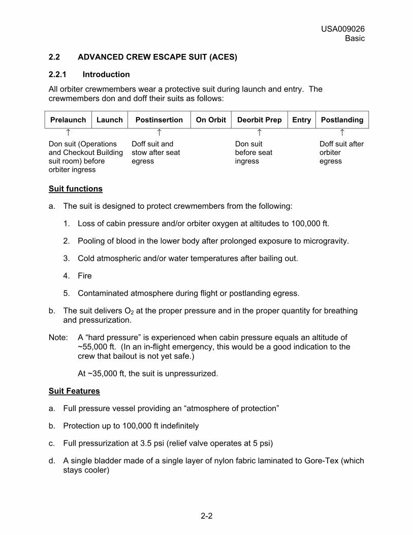
All orbiter crewmembers wear a protective suit during launch and entry. The crewmembers don and doff their suits as follows:
Prelaunch Launch Postinsertion On Orbit Deorbit Prep Entry Postlanding
↑ ↑ ↑ ↑ Don suit (Operations and Checkout Building suit room) before orbiter ingress
Doff suit and stow after seat egress
Don suit before seat ingress
Doff suit after orbiter egress
Suit functions
a. The suit is designed to protect crewmembers from the following:
1. Loss of cabin pressure and/or orbiter oxygen at altitudes to 100,000 ft.
2. Pooling of blood in the lower body after prolonged exposure to microgravity.
3. Cold atmospheric and/or water temperatures after bailing out.
4. Fire
5. Contaminated atmosphere during flight or postlanding egress.
b. The suit delivers O2 at the proper pressure and in the proper quantity for breathing and pressurization.
Note: A �hard pressure� is experienced when cabin pressure equals an altitude of ~55,000 ft. (In an in-flight emergency, this would be a good indication to the crew that bailout is not yet safe.)
At ~35,000 ft, the suit is unpressurized.
Suit Features
a. Full pressure vessel providing an �atmosphere of protection�
b. Protection up to 100,000 ft indefinitely
c. Full pressurization at 3.5 psi (relief valve operates at 5 psi)
d. A single bladder made of a single layer of nylon fabric laminated to Gore-Tex (which stays cooler)
USA009026 Basic
2-3
e. Single neck dam dividing the helmet volume from the suit volume
f. Six pressure seals:
1. Helmet visor
2. Neck dam
3. Main suit zipper
4. Bioinstrumentation Passthrough (BIP) plug
5. Right glove
6. Left glove
g. Nonintegrated g-suit
h. Gloves required for suit pressurization
1. Gloves connect to ACES via wrist disconnects
2. Gloves must be worn to keep water out
i. Loose fit; adequate mobility.
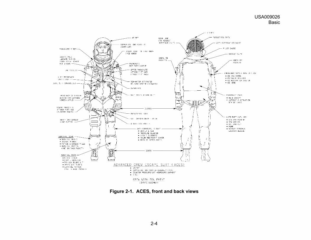
The Advanced Crew Escape Suit (ACES) is shown in Figure 2-1 below.
USA009026 Basic
2-4
Figure 2-1. ACES, front and back views
USA009026 Basic
2-5
2.2.2 ACES Features
The ACES has the following features:
a. A full pressure suit, the air pressure exerts direct pressure on the body. The orange outer garment of flame-retardant Nomex covers the single pressure bladder.
b. The detachable anti-g suit can be demated before launch and remated before entry.
c. The gloves are attached to the suit by disconnects and pressurize when the suit is pressurized.
d. The waterproof main zipper seals out water.
e. The vent connection has a flapper valve to prevent water from entering.
f. The single neck dam separates the helmet volume from the suit volume. The neck dam also prevents water from entering the suit when the helmet visor is open.
g. The neck ring tiedown is used to adjust the position of the neck ring.
Subsequent subsections describe the following ACES features in more detail:
a. ACES O2 flow, Pressure system
b. Pressure system components
c. Anti-g protection
d. O2 manifold/g-suit controller assembly
e. Cooling
f. Gloves, boots
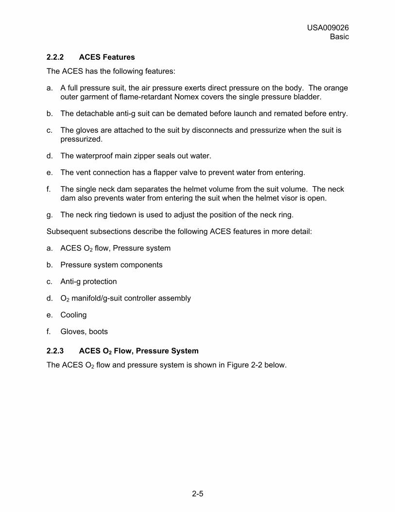
2.2.3 ACES O2 Flow, Pressure System
The ACES O2 flow and pressure system is shown in Figure 2-2 below.
USA009026 Basic
2-6
Figure 2-2. ACES oxygen flow and pressure system
USA009026 Basic
2-7
2.2.4 Pressure System Components
The ACES, a full pressure suit, is a pressure vessel. The single pressure bladder covers all but a crewmember�s head and hands.
The pressure on the crewmember�s body is atmospheric and the pressure is being exerted directly and providing �an atmosphere of protection� indefinitely from a loss of cabin pressure to 100,000 ft.
The pressure bladder is constructed of a single nylon layer laminated to Gore-Tex and is restrained with an integral-like cover.
a. The single layer makes the ACES looser fitting, giving the crewmember greater freedom of movement and comfort.
b. The Gore-Tex is porous and �breathes� (helping the crewmember stay cooler), but seals when air pressure is applied.
Besides the pressure bladder, the ACES pressure system includes the following components:
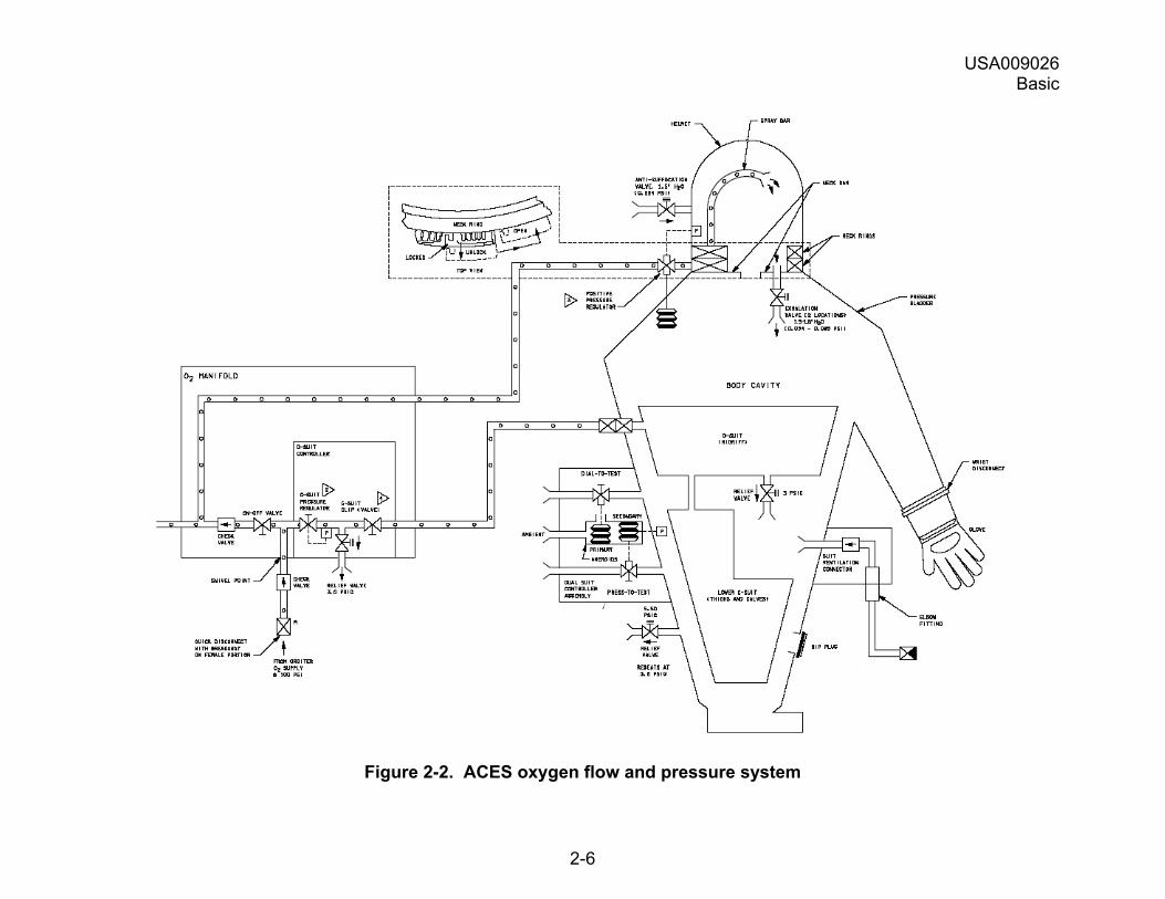
2.2.4.1 Dual Suit Controller Characteristics/Function
Located on right side of suit chest (depicted below, with manual controls detailed).
Opens and closes to regulate suit pressure.
Figure 2-3. Dual suit controller
USA009026 Basic
2-8
The controller includes dual (redundant) aneroids that operate in auto and test modes:
Auto Mode
In auto mode, the dual suit controller operates as follows:
a. The dual suit controller maintains suit pressure, based on ambient pressure conditions. It will maintain total pressure (ambient cabin pressure + suit pressure) of 3.67 psia. For example, an ambient pressure of 1.00 psi (~60,000 ft) would require a suit pressure of 2.67 psig. The valve assembly is normally open, preventing suit pressurization when the helmet visor is closed.
b. The primary aneroid assembly closes at 3.24 - 3.67 psia ambient pressure to maintain a 34,000 - 36,500 ft suit pressure altitude.
c. The secondary aneroid assembly closes at 3.05 - 3.48 psia ambient pressure to maintain a 35,000 - 38,000 ft suit pressure altitude.
Test Mode
The suit controller has the two following means of testing ACES pressurization:
a. Dial-to-Test feature � When the knurled knob in the center of the controller is turned clockwise approximately one rotation, it closes the primary aneroid assembly regardless of altitude. If the helmet visor is closed and locked, crewmember exhalation pressurizes the suit bladder to ~3.5 psi. Once inflated this way, the suit bladder remains pressurized (even if the visor is later opened) until the knob is turned one full turn counterclockwise.
b. Press-to-Test button � Also located near the center of the suit controller. If the helmet visor is closed and locked, depressing the button closes the secondary aneroid assembly and allows the suit bladder to inflate to 2.3 psi as long as the button remains depressed.
Note: If you find your suit pressurizing unexpectedly:
1. You may have inadvertently closed the Dial-to-Test knob (primary aneroid assembly)
or
2. You may be pressing in on the Press-to-Test button (secondary aneroid assembly)
USA009026 Basic
2-9
2.2.4.2 Suit O2 Regulator Characteristics/Function
During normal use, pressurized O2 from the orbiter supply enters the helmet through the positive pressure regulator when the crewmember inhales. The positive pressure regulator maintains the pressure inside the helmet at 0.8-1.4 in of water (0.0289-0.0505 psi) above the pressure inside the suit.
Note: If breathing cavity integrity is compromised, the regulator will freeflow O2 at a rate of 90 liters per minute.
2.2.4.3 Exhalation Valves Characteristics/Function
Two exhalation valves between the helmet cavity and the suit bladder will open if the pressure inside the helmet is 1.5-1.8 in of water (0.054-0.085 psi). This will happen during exhalation. Exhaled air passes into the suit bladder and out the dual suit controller on the right side of the chest.
2.2.4.4 ACES Relief Valve Characteristics/Function
The ACES relief valve is located in the right leg area. The valve opens when suit bladder pressure reaches 5.5 ± 0.2 psi. Once open, the valve stays open until pressure in the suit bladder is reduced to 3.5 ± 0.02 psi.
2.2.5 Anti-g Protection
Crewmembers wear a g-suit for entry that provides pressure to the lower body separate from the ACES. The applied pressure prevents blood from pooling in the lower extremities upon return to 1-g conditions after two or more days of microgravity.
Crewmembers wearing the ACES suit do not wear a g-suit for launch. The g-suit is stowed prelaunch, then donned and mated for entry.
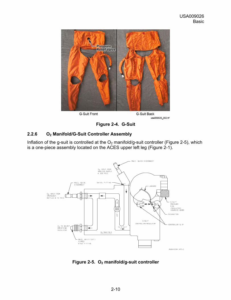
The g-suit (Figure 2-4) has an abdominal bladder and leg bladders that do not cover the entire leg.
USA009026 Basic
2-10
Figure 2-4. G-Suit
2.2.6 O2 Manifold/G-Suit Controller Assembly
Inflation of the g-suit is controlled at the O2 manifold/g-suit controller (Figure 2-5), which is a one-piece assembly located on the ACES upper left leg (Figure 2-1).
Figure 2-5. O2 manifold/g-suit controller
USA009026 Basic
2-11
The functional features of the O2 manifold/g-suit controller assembly are as follows:
2.2.6.1 O2 Hose Fittings Characteristics/Function There are three O2 hose fittings on the assembly:
a. A male swivel fitting connects to the orbiter O2 supply hose. This fitting is provided with a quick disconnect.
b. A second male fitting, also a quick disconnect, connects the manifold with the emergency O2 bottles in the parachute harness.
Note: The emergency O2 system does not provide g-suit protection.
c. A third (threaded) male fitting connects the manifold with the suit O2 regulator for crew respiration.
2.2.6.2 G-suit Controller Characteristics/Function The controller inflates the g-suit bladders when the manifold is connected to orbiter O2 and the g-suit pressure dial (knurled knob) is turned clockwise (in the direction of the arrow).
The controller inflates the suit bladder 0.5 psi with each complete turn (indicated by a slight detent), to 2.5 psi max.
Note: Entry Checklist calls for 1.5 psi, or three complete turns.
Note: If you find the g-suit inflating unexpectedly, check that the g-suit pressure dial (knurled knob) is completely counterclockwise.
A one-way valve inside the manifold keeps the suit from inflating with emergency O2, which is reserved for breathing.
2.2.6.3 G-suit Controller Clip Characteristics/Function When the controller clip is pulled free, it:
a. Traps the current volume of O2 inside the g-suit bladders and prevents any deflation, even if orbiter O2 is disconnected from the manifold.
b. Prevents the g-suit from being inflated or deflated.
Reinstalling the clip allows the g-suit bladders to deflate or inflate.
2.2.6.4 G-suit Relief Valve Characteristics/Function Located on the abdominal bladder of the g-suit. The valve operates as follows:
a. It vents pressure in excess of 3.0 psi out of the g-suit bladders.
b. Once open, the valve stays open until bladder pressure has been reduced to 2.5 psi.
USA009026 Basic
2-12
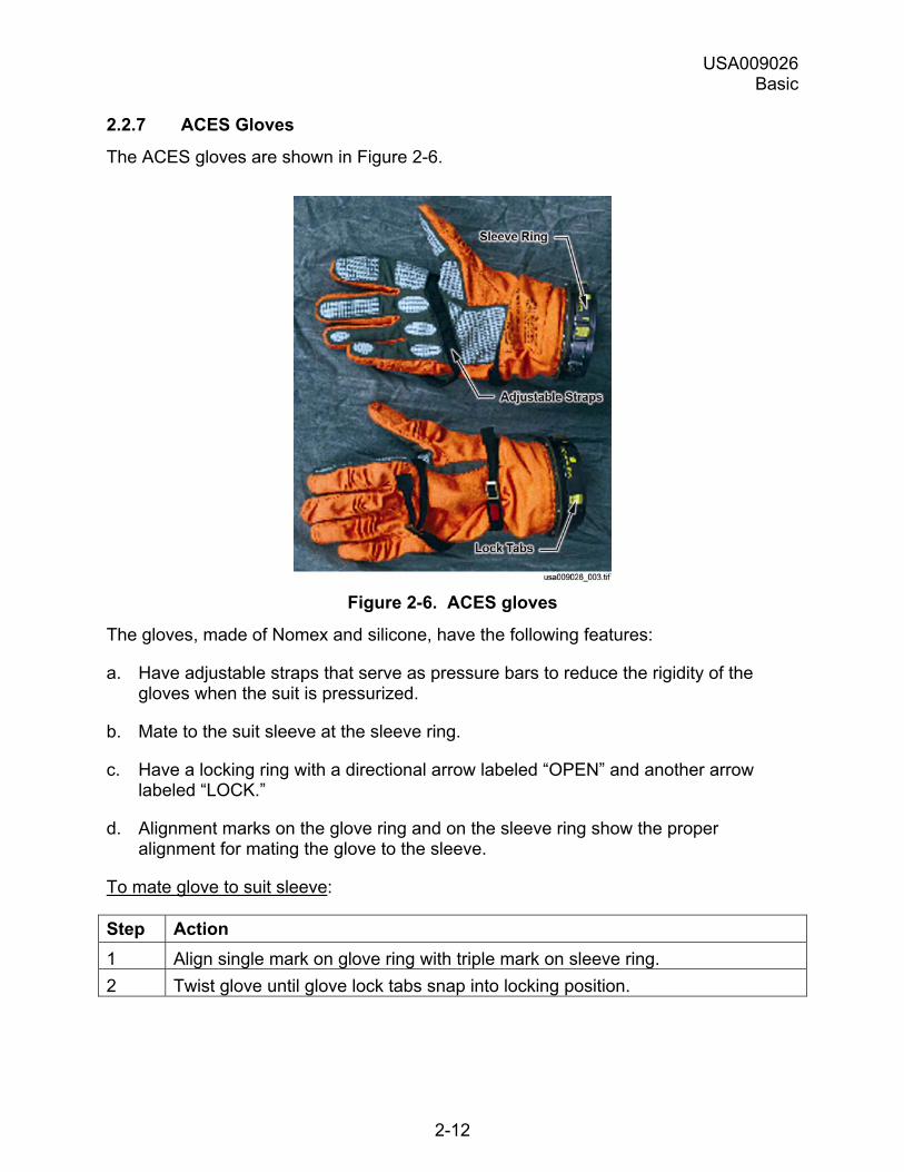
2.2.7 ACES Gloves
The ACES gloves are shown in Figure 2-6.
Figure 2-6. ACES gloves
The gloves, made of Nomex and silicone, have the following features:
a. Have adjustable straps that serve as pressure bars to reduce the rigidity of the gloves when the suit is pressurized.
b. Mate to the suit sleeve at the sleeve ring.
c. Have a locking ring with a directional arrow labeled �OPEN� and another arrow labeled �LOCK.�
d. Alignment marks on the glove ring and on the sleeve ring show the proper alignment for mating the glove to the sleeve.
To mate glove to suit sleeve:
Step Action 1 Align single mark on glove ring with triple mark on sleeve ring. 2 Twist glove until glove lock tabs snap into locking position.
USA009026 Basic
2-13
To demate glove from suit sleeve:
Step Action 1 Release and hold two locking tabs while twisting glove fully to mechanical stop. 2 Remove glove.
Each glove has a colored Velcro patch that helps identify individual crewmembers (see last paragraph).
2.2.8 Boots
The boots, made of leather, Nomex, and rubber, are equipped with lacing for fit adjustment. Each boot has a colored Velcro patch with a letter for crewmember identification during SAR operations (see next paragraph).
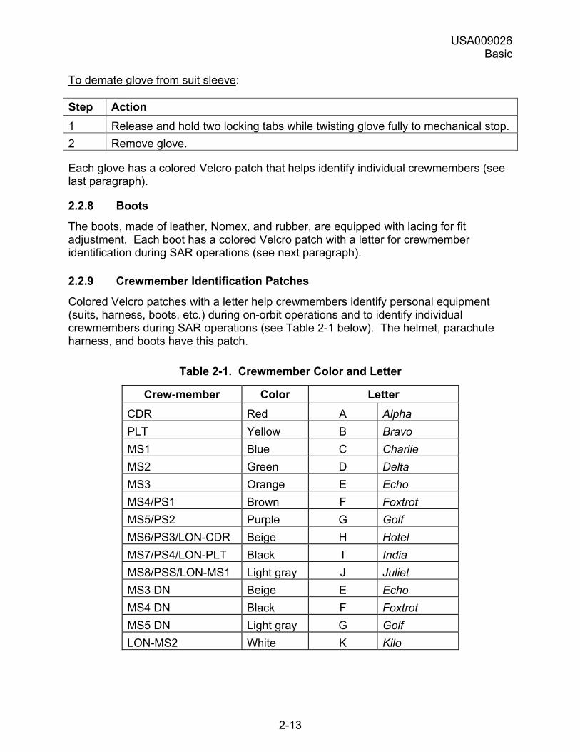
2.2.9 Crewmember Identification Patches
Colored Velcro patches with a letter help crewmembers identify personal equipment (suits, harness, boots, etc.) during on-orbit operations and to identify individual crewmembers during SAR operations (see Table 2-1 below). The helmet, parachute harness, and boots have this patch.
Table 2-1. Crewmember Color and Letter
Crew-member Color Letter CDR Red A Alpha PLT Yellow B Bravo MS1 Blue C Charlie MS2 Green D Delta MS3 Orange E Echo MS4/PS1 Brown F Foxtrot MS5/PS2 Purple G Golf MS6/PS3/LON-CDR Beige H Hotel MS7/PS4/LON-PLT Black I India MS8/PSS/LON-MS1 Light gray J Juliet MS3 DN Beige E Echo MS4 DN Black F Foxtrot MS5 DN Light gray G Golf LON-MS2 White K Kilo
USA009026 Basic
2-14
2.3 HELMET, COMM CARRIER ASSEMBLY, HEADSET INTERFACE UNIT
2.3.1 Introduction
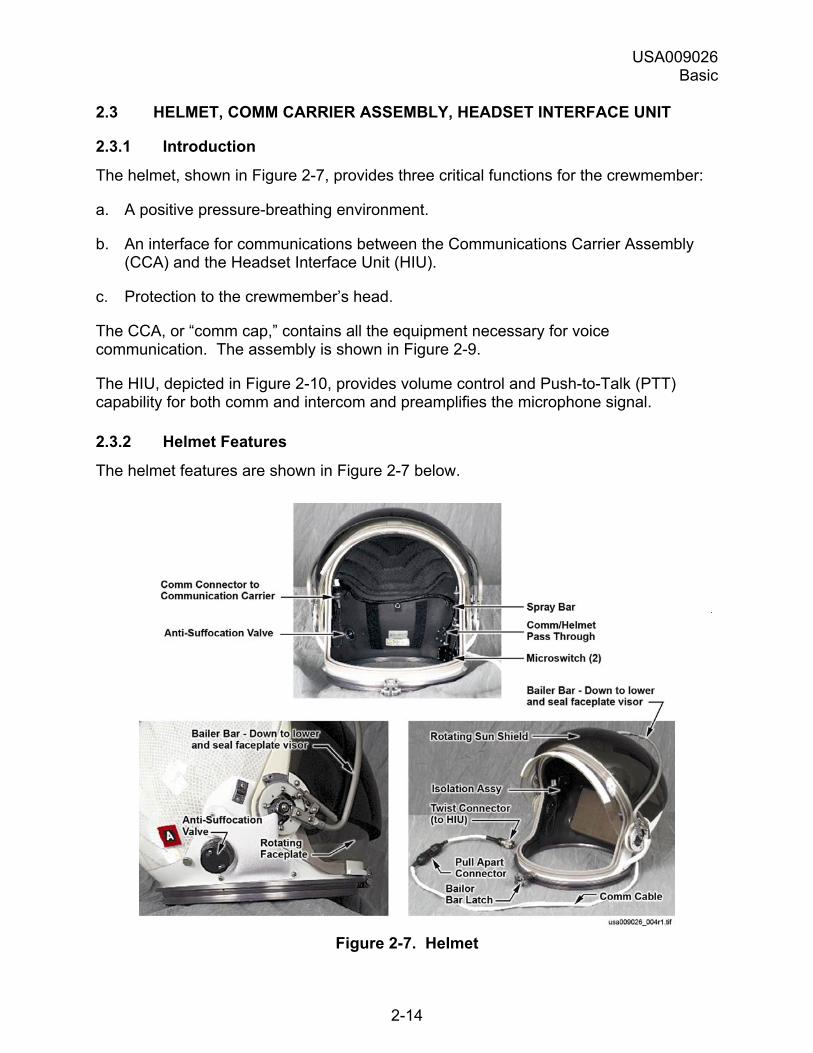
The helmet, shown in Figure 2-7, provides three critical functions for the crewmember:
a. A positive pressure-breathing environment.
b. An interface for communications between the Communications Carrier Assembly (CCA) and the Headset Interface Unit (HIU).
c. Protection to the crewmember�s head.
The CCA, or �comm cap,� contains all the equipment necessary for voice communication. The assembly is shown in Figure 2-9.
The HIU, depicted in Figure 2-10, provides volume control and Push-to-Talk (PTT) capability for both comm and intercom and preamplifies the microphone signal.
2.3.2 Helmet Features
The helmet features are shown in Figure 2-7 below.
Figure 2-7. Helmet
USA009026 Basic
2-15
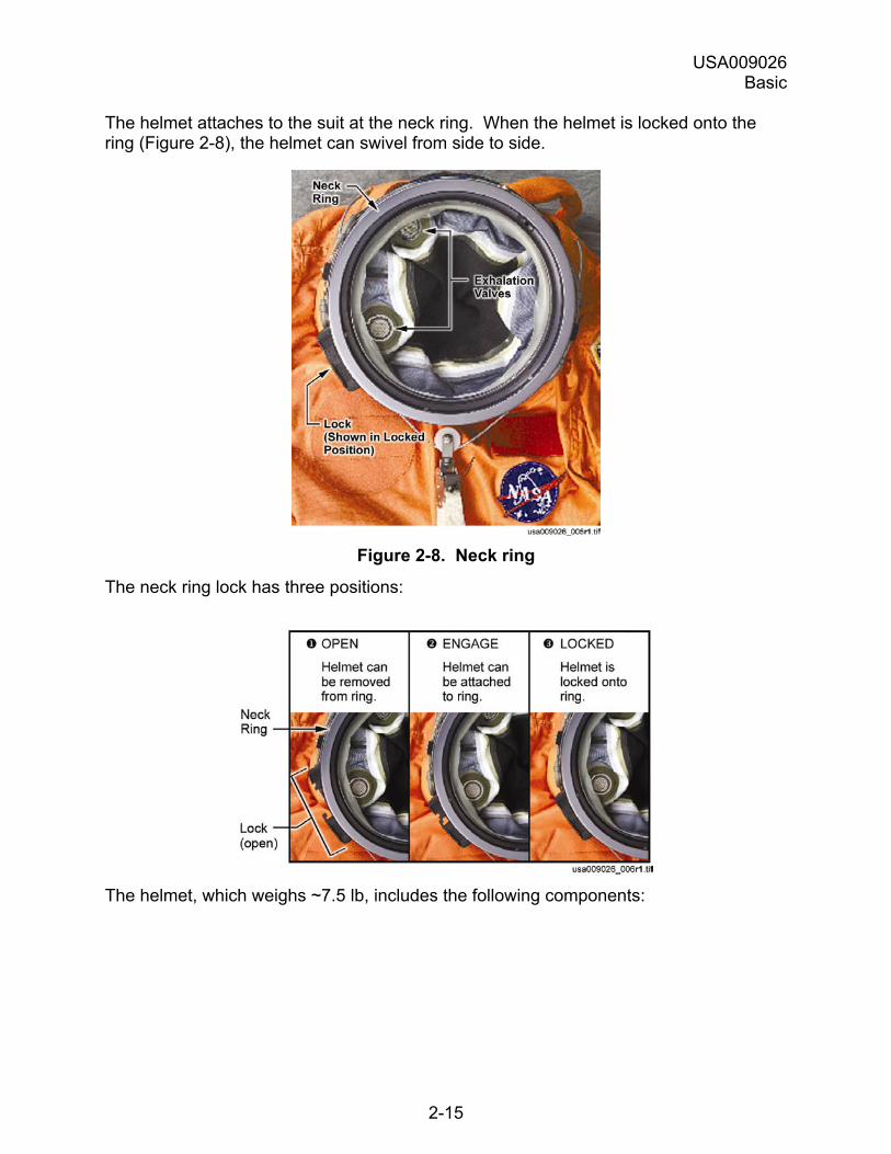
The helmet attaches to the suit at the neck ring. When the helmet is locked onto the ring (Figure 2-8), the helmet can swivel from side to side.
Figure 2-8. Neck ring
The neck ring lock has three positions:
The helmet, which weighs ~7.5 lb, includes the following components:

USA009026 Basic
2-16
2.3.2.1 Pressure Visor
A pressure visor that operates as follows:
a. To CLOSE, release neck dam tabs, grasp white tabs on rim of clear visor, and pull down.
b. To LOCK, pull bailer bar down into bailer bar latch.
c. To UNLOCK/RAISE:
1. Push ribbed locking lever down
2. Squeeze together two buttons on either side of bailer bar latch
3. Manually raise visor
CAUTION
Do not close visor by pulling down on bailer bar. Doing so will damage the
mechanism.
2.3.2.2 Rotating Sun Visor
A tinted sunshade is mounted to the outside of the helmet with a continuous friction hinge.
Can be lowered/raised independently of the clear visor.
2.3.2.3 Comm Cable/Comm Pigtail
The comm cable exiting the back of the helmet is equipped with a quick disconnect for egress/bailout. It connects to the comm pigtail, which in turn connects to the HIU.
An extra pigtail (connected to an extra HIU) is carried on the flight deck. Refer to flight specific crew worn carry on drawing for location.
2.3.2.4 Anti-Suffocation Valve
Located at the lower right rear of the helmet.
Allows ambient air outside the helmet to enter when:
a. Visor is closed.
b. Breathing O2 is not available.
USA009026 Basic
2-17
The anti-suffocation valve opens when pressure inside the helmet is 1.5 in. water (0.054 psi) less than the pressure outside the helmet (as happens when a crewmember inhales with the visor closed and no O2 is being supplied).
Note: The anti-suffocation valve will allow water into the helmet if submerged.
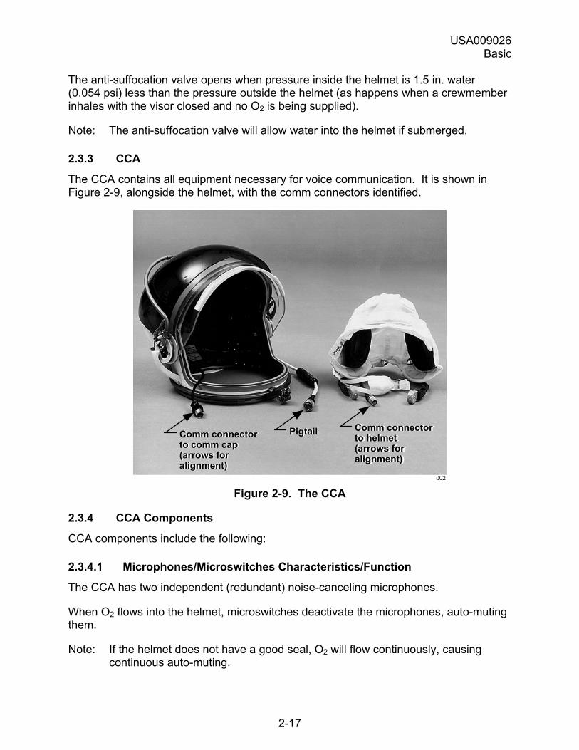
2.3.3 CCA
The CCA contains all equipment necessary for voice communication. It is shown in Figure 2-9, alongside the helmet, with the comm connectors identified.
Comm connectorto comm cap(arrows foralignment)
Comm connectorto comm cap(arrows foralignment)
Comm connectorto helmet(arrows foralignment)
Comm connectorto helmet(arrows foralignment)
PigtailPigtail
002 Figure 2-9. The CCA
2.3.4 CCA Components
CCA components include the following:
2.3.4.1 Microphones/Microswitches Characteristics/Function
The CCA has two independent (redundant) noise-canceling microphones.
When O2 flows into the helmet, microswitches deactivate the microphones, auto-muting them.
Note: If the helmet does not have a good seal, O2 will flow continuously, causing continuous auto-muting.
USA009026 Basic
2-18
2.3.4.2 Earphones Characteristics/Function
The CCA has two independent (redundant) padded, earmuff-type earphones.
2.3.4.3 Connector Characteristics/Function
The comm cap interfaces with the helmet via a connector. See Figure 2-9.
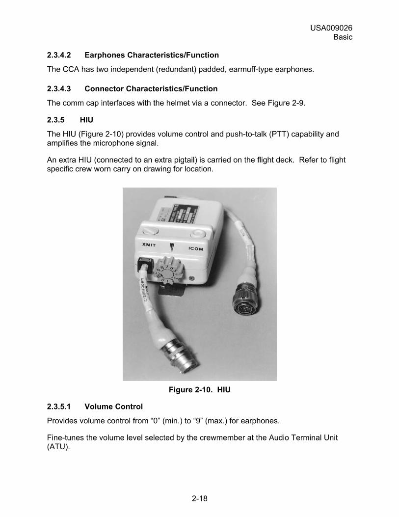
2.3.5 HIU
The HIU (Figure 2-10) provides volume control and push-to-talk (PTT) capability and amplifies the microphone signal.
An extra HIU (connected to an extra pigtail) is carried on the flight deck. Refer to flight specific crew worn carry on drawing for location.
Figure 2-10. HIU
2.3.5.1 Volume Control
Provides volume control from �0� (min.) to �9� (max.) for earphones.
Fine-tunes the volume level selected by the crewmember at the Audio Terminal Unit (ATU).
USA009026 Basic
2-19
2.3.5.2 �XMIT� PTT Button
Provides push-to-talk capability for transmitting on the Air-to-Air (A/A) and Air-to-Ground (A/G) loops.
The top surface of the button has a ridge (or �rib�) across the diameter for easy identification by touch.
2.3.5.3 �ICOM� PTT Button
Provides push-to-talk capability for transmitting on the intercom loops.
The top surface of the button is concave (�like a corpuscle�) for easy identification by touch.
2.3.5.4 Retainer Clip
Allows unit to be attached to crew clothing during on-orbit operations.
2.3.5.5 Preamplifier
Amplifies the signal from comm cap microphones.
2.4 COOLING SYSTEMS
2.4.1 Introduction
Each crewmember is provided with a cooling system. There are two models that utilize thermal electric modules for suit cooling: Individual Cooling Units (ICUs) and Thermal Electric Liquid Cooling Units (TELCUs), also known as �two-person cooling units.�
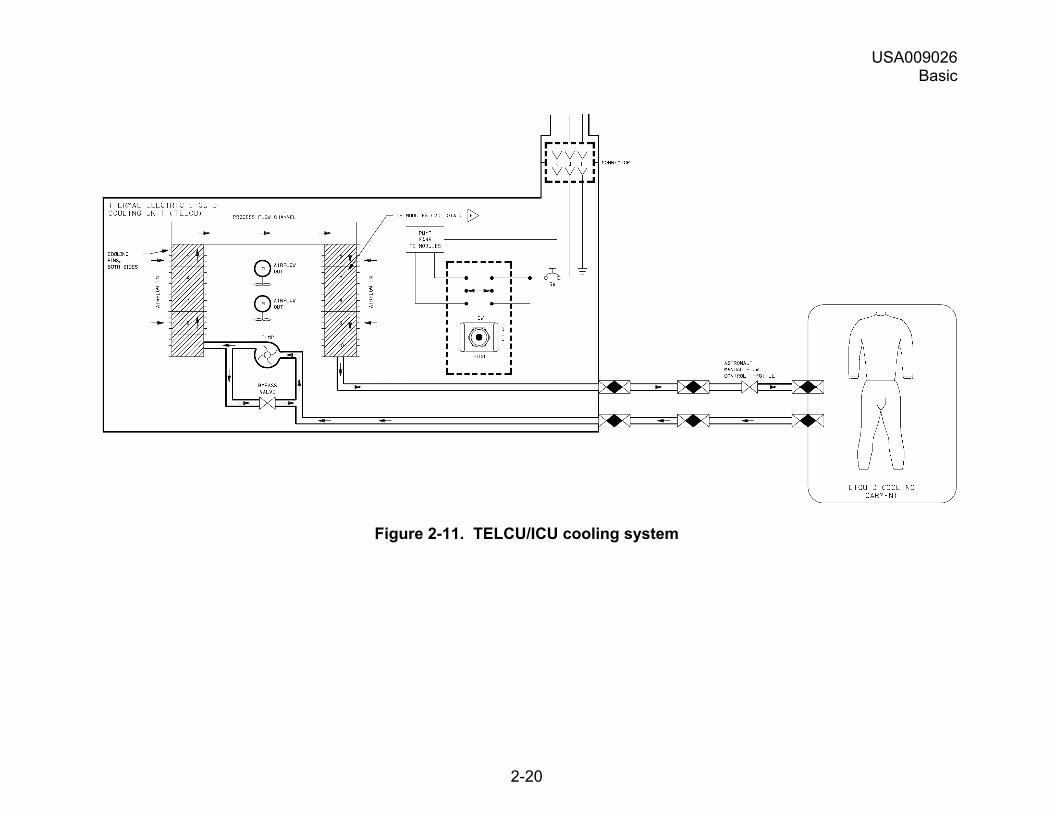
2.4.2 TELCU/ICU Cooling
The two main components of the TELCU/ICU cooling system are:
a. The TELCU/ICU that cools the water flowing through the network of vinyl tubing in the Liquid Cooling Garment (LCG).
b. The two-piece LCG worn by crewmembers as an undergarment.
The TELCU/ICU cooling system is shown in Figure 2-11.
USA009026 Basic
2-20
Figure 2-11. TELCU/ICU cooling system
USA009026 Basic
2-21
The stages in the TELCU/ICU cooling system are as follows:
Stage Action 1 Water from the liquid cooling garment enters the cooling side of the
TELCU/ICU cooling core. 2 Two conductors are connected and a direct current is passed throughout the
circuit. The temperature of one of the conductors decreases and the temperature of the other conductor increases. The cold conductor absorbs heat from its environment, and the hot conductor rejects heat to its environment. A pair of cooling fans aids the process.
3 The TELCU/ICU pump delivers the cooled water through the TELCU/ICU lines to the LCG lines via quick disconnects at the Bioinstrumentation Passthrough (BIP).
4 The cooled water circulates through the vinyl tubing network of the LCG worn by the crewmember.
5 The water becomes warmer during the heat exchange and returns to the TELCU/ICU, where the process starts over.
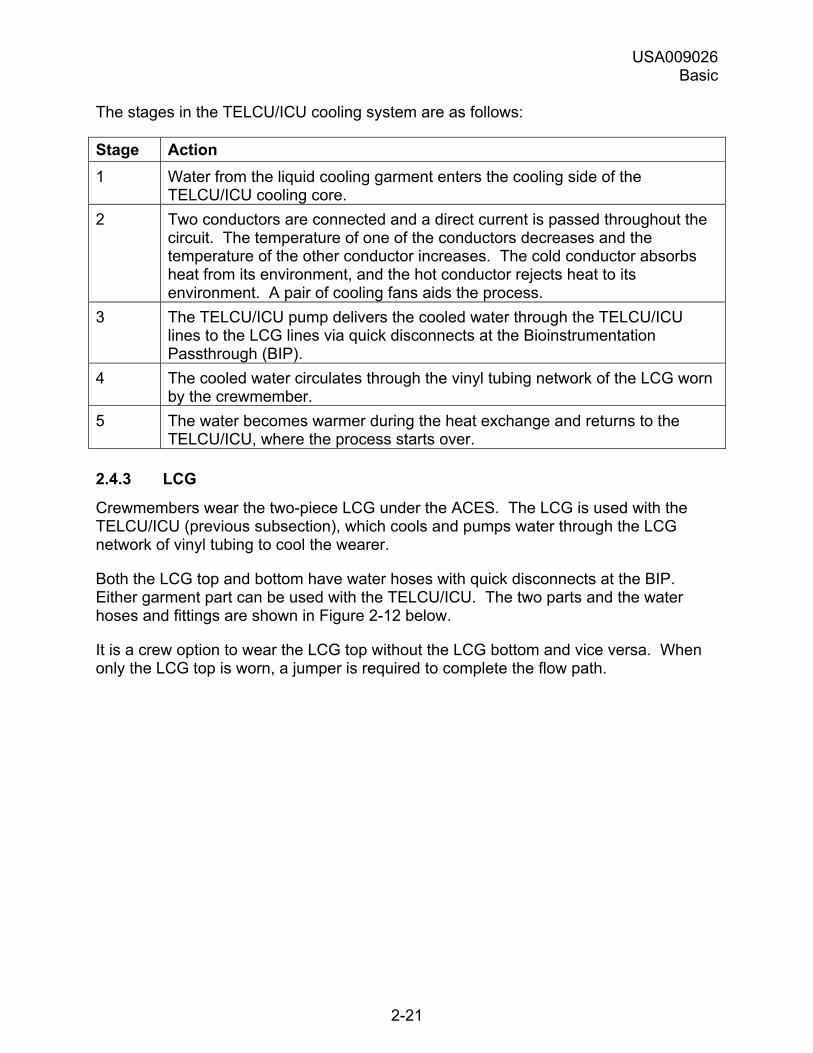
2.4.3 LCG
Crewmembers wear the two-piece LCG under the ACES. The LCG is used with the TELCU/ICU (previous subsection), which cools and pumps water through the LCG network of vinyl tubing to cool the wearer.
Both the LCG top and bottom have water hoses with quick disconnects at the BIP. Either garment part can be used with the TELCU/ICU. The two parts and the water hoses and fittings are shown in Figure 2-12 below.
It is a crew option to wear the LCG top without the LCG bottom and vice versa. When only the LCG top is worn, a jumper is required to complete the flow path.
USA009026 Basic
2-22
Figure 2-12. LCG
2.5 PARACHUTE HARNESS, PERSONAL PARACHUTE ASSEMBLY
2.5.1 Introduction
The parachute harness, which supports the crewmember�s body weight, attaches to the Personal Parachute Assembly (PPA) containing the parachute system. Both the harness and the PPA include survival and rescue gear.
The harness and the PPA are discussed in separate subsections that follow. The rescue and survival gear associated with each system is described in Section 2.6.
2.5.2 Parachute Harness
The parachute harness has:
a. Straps that support the crewmember.
b. Fittings/snaps that attach the harness to the parachute.
USA009026 Basic
2-23
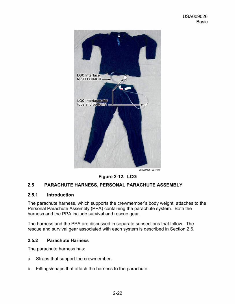
c. Items that may be needed in an emergency:
1. Emergency Oxygen System (EOS)
2. Life Preserver Unit (LPU)
3. Carabiner
4. Emergency drinking water
These elements are shown in Figure 2-13 and on the next page. Harness elements are described in the table that follows (for the rescue and survival gear, refer to Section 2.6).
Figure 2-13. Parachute harness (upper portion)
The parachute harness elements include the following:
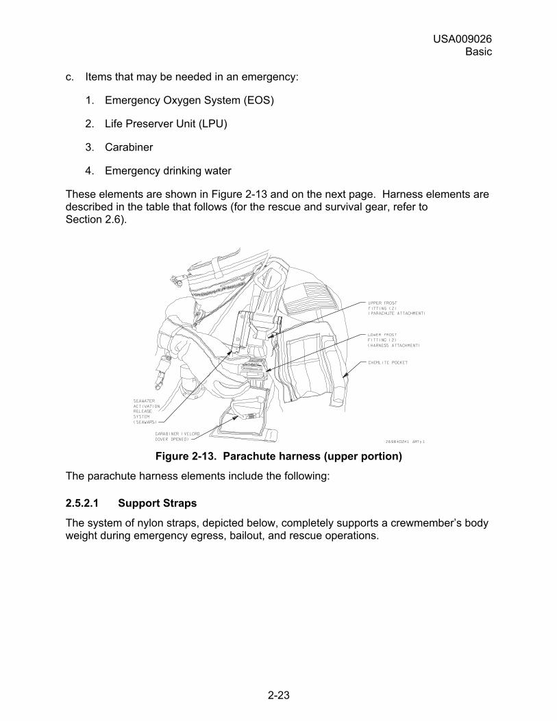
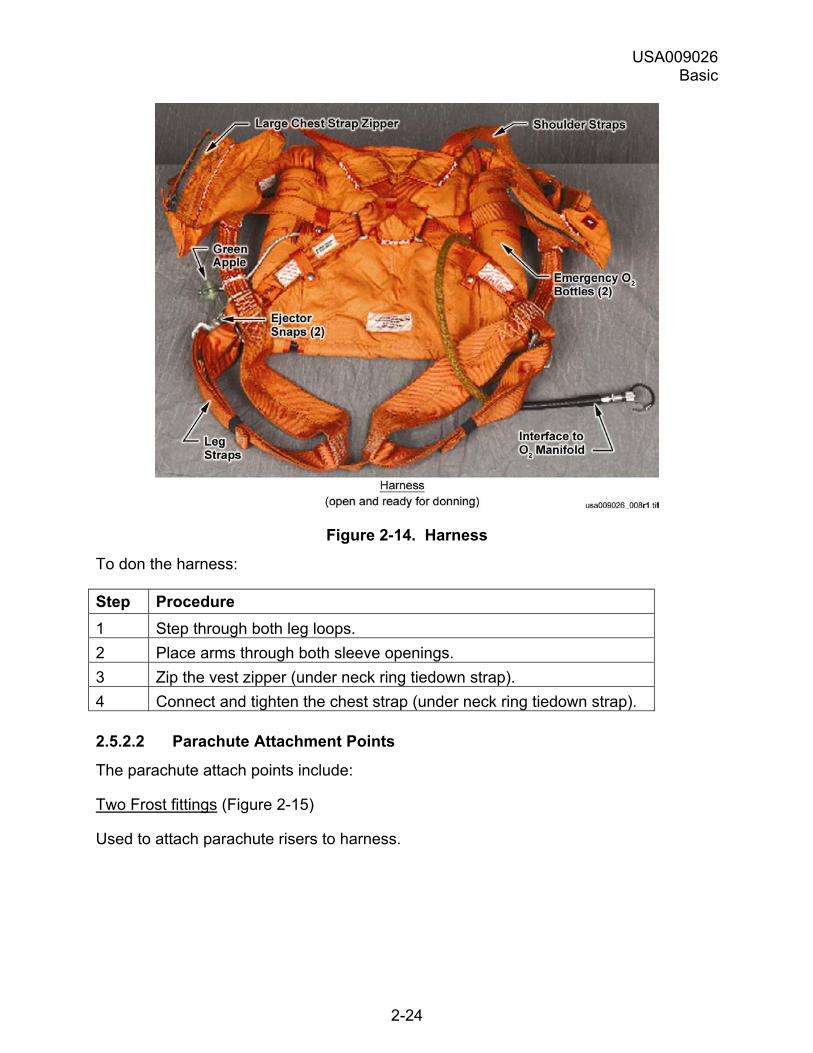
2.5.2.1 Support Straps
The system of nylon straps, depicted below, completely supports a crewmember�s body weight during emergency egress, bailout, and rescue operations.
USA009026 Basic
2-24
Figure 2-14. Harness
To don the harness:
Step Procedure 1 Step through both leg loops. 2 Place arms through both sleeve openings. 3 Zip the vest zipper (under neck ring tiedown strap). 4 Connect and tighten the chest strap (under neck ring tiedown strap).
2.5.2.2 Parachute Attachment Points
The parachute attach points include:
Two Frost fittings (Figure 2-15)
Used to attach parachute risers to harness.
USA009026 Basic
2-25
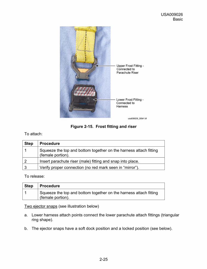
Figure 2-15. Frost fitting and riser
To attach:
Step Procedure 1 Squeeze the top and bottom together on the harness attach fitting
(female portion). 2 Insert parachute riser (male) fitting and snap into place. 3 Verify proper connection (no red mark seen in �mirror�).
To release:
Step Procedure 1 Squeeze the top and bottom together on the harness attach fitting
(female portion).
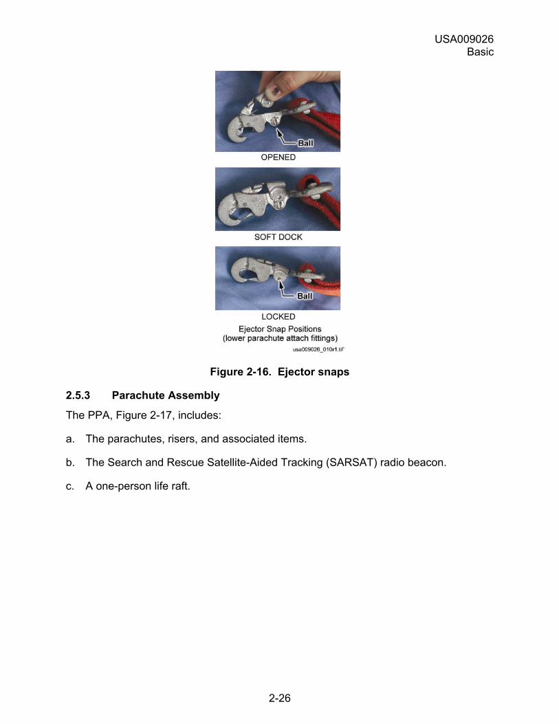
Two ejector snaps (see illustration below)
a. Lower harness attach points connect the lower parachute attach fittings (triangular ring shape).
b. The ejector snaps have a soft dock position and a locked position (see below).
USA009026 Basic
2-26
Figure 2-16. Ejector snaps
2.5.3 Parachute Assembly
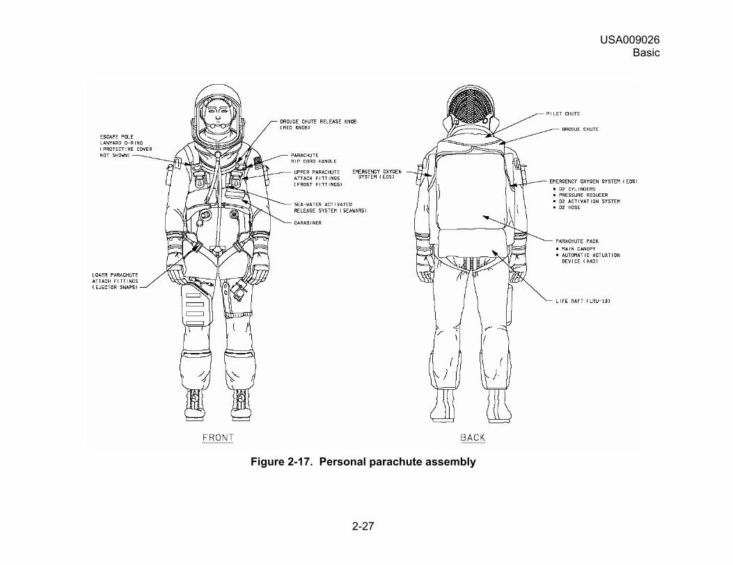
The PPA, Figure 2-17, includes:
a. The parachutes, risers, and associated items.
b. The Search and Rescue Satellite-Aided Tracking (SARSAT) radio beacon.
c. A one-person life raft.
USA009026 Basic
2-27
Figure 2-17. Personal parachute assembly
USA009026 Basic
2-28
The PPA is:
a. Used as a seat back cushion.
b. Placed on the crew seats before ingress.
c. Connected during prelaunch to the parachute harness at four attach points.
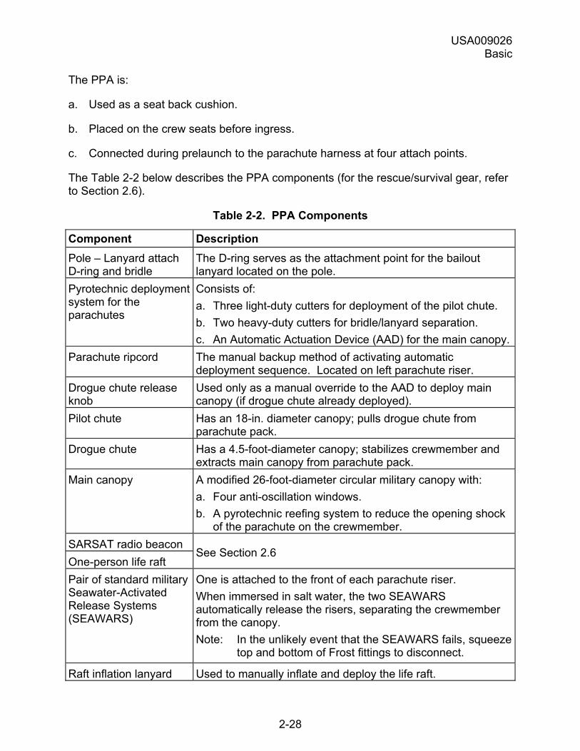
The Table 2-2 below describes the PPA components (for the rescue/survival gear, refer to Section 2.6).
Table 2-2. PPA Components
Component Description Pole � Lanyard attach D-ring and bridle
The D-ring serves as the attachment point for the bailout lanyard located on the pole.
Pyrotechnic deployment system for the parachutes
Consists of: a. Three light-duty cutters for deployment of the pilot chute. b. Two heavy-duty cutters for bridle/lanyard separation. c. An Automatic Actuation Device (AAD) for the main canopy.
Parachute ripcord The manual backup method of activating automatic deployment sequence. Located on left parachute riser.
Drogue chute release knob
Used only as a manual override to the AAD to deploy main canopy (if drogue chute already deployed).
Pilot chute Has an 18-in. diameter canopy; pulls drogue chute from parachute pack.
Drogue chute Has a 4.5-foot-diameter canopy; stabilizes crewmember and extracts main canopy from parachute pack.
Main canopy A modified 26-foot-diameter circular military canopy with: a. Four anti-oscillation windows. b. A pyrotechnic reefing system to reduce the opening shock
of the parachute on the crewmember. SARSAT radio beacon One-person life raft
See Section 2.6
Pair of standard military Seawater-Activated Release Systems (SEAWARS)
One is attached to the front of each parachute riser. When immersed in salt water, the two SEAWARS automatically release the risers, separating the crewmember from the canopy. Note: In the unlikely event that the SEAWARS fails, squeeze
top and bottom of Frost fittings to disconnect.
Raft inflation lanyard Used to manually inflate and deploy the life raft.
USA009026 Basic
2-29
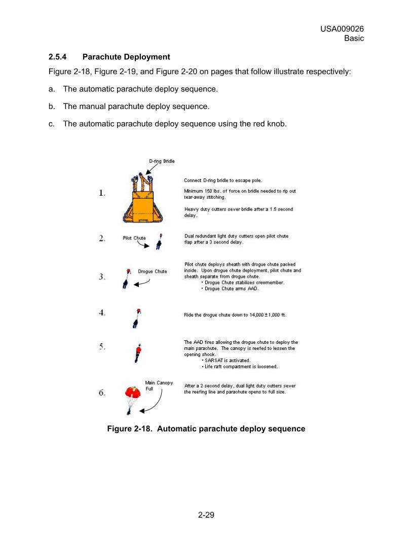
2.5.4 Parachute Deployment
Figure 2-18, Figure 2-19, and Figure 2-20 on pages that follow illustrate respectively:
a. The automatic parachute deploy sequence.
b. The manual parachute deploy sequence.
c. The automatic parachute deploy sequence using the red knob.
Figure 2-18. Automatic parachute deploy sequence
USA009026 Basic
2-30
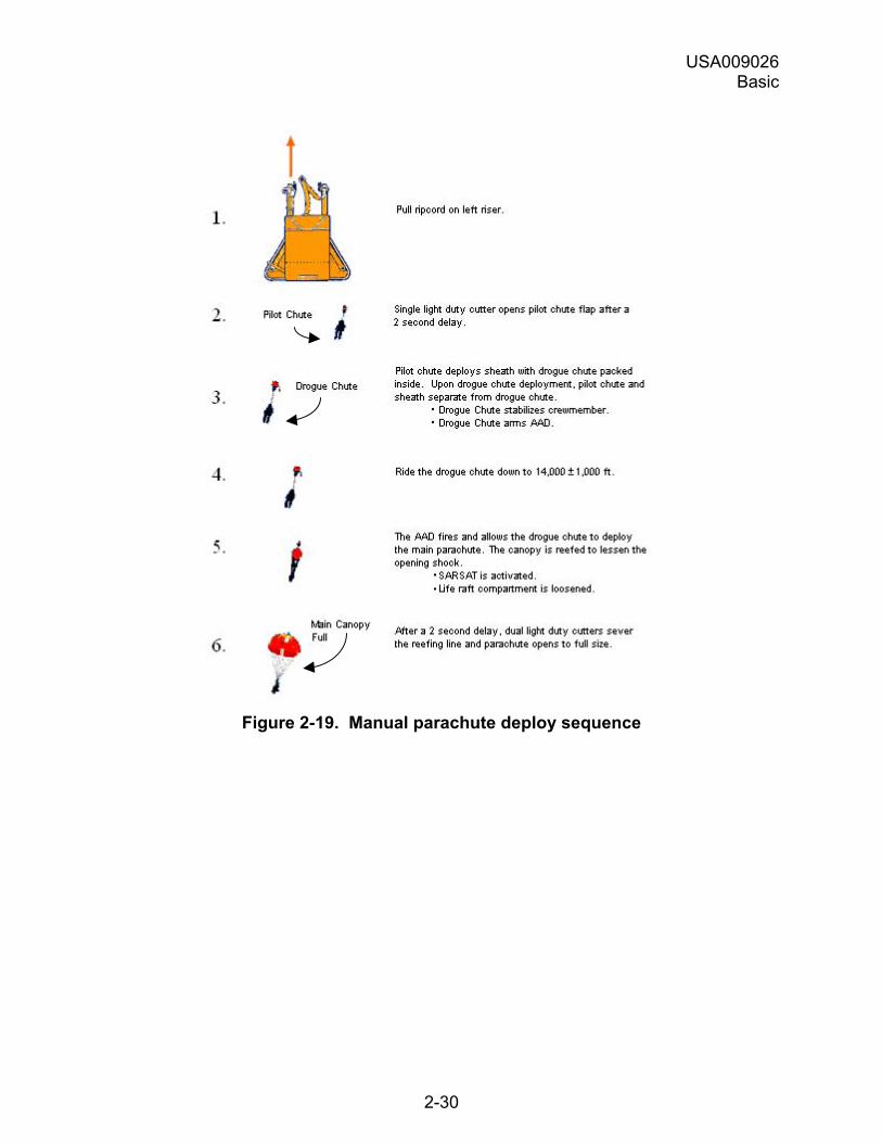
Figure 2-19. Manual parachute deploy sequence
USA009026 Basic
2-31
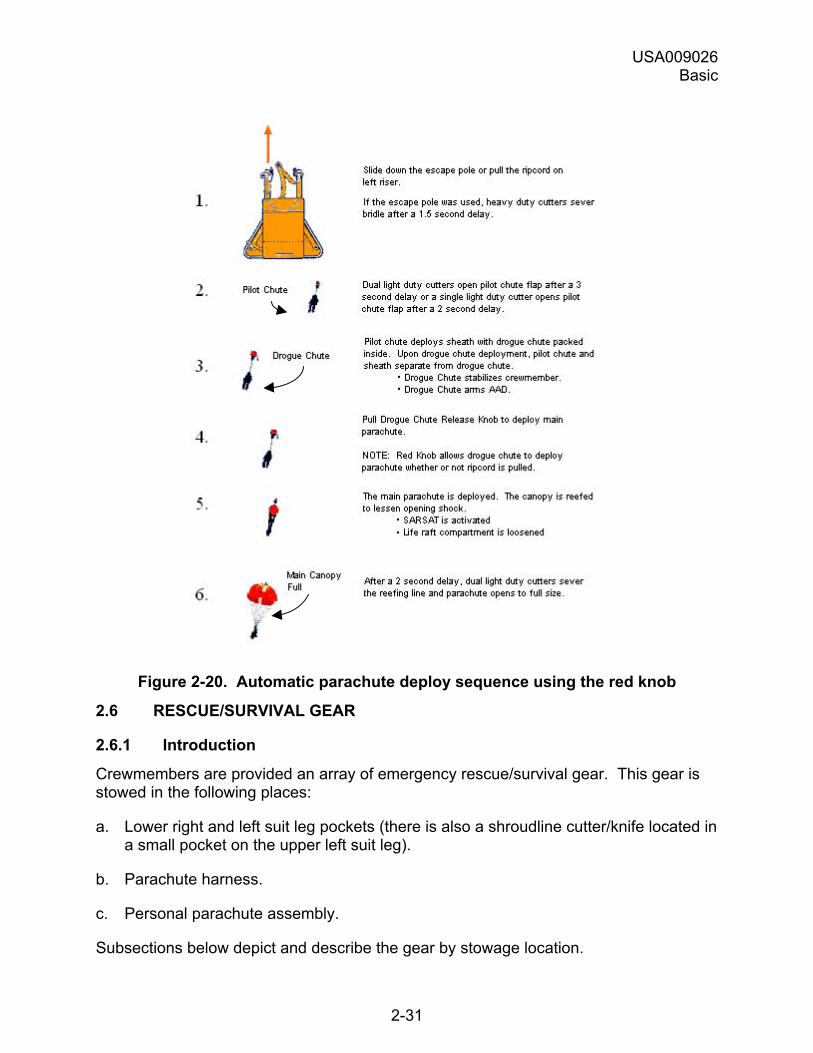
Figure 2-20. Automatic parachute deploy sequence using the red knob
2.6 RESCUE/SURVIVAL GEAR
2.6.1 Introduction
Crewmembers are provided an array of emergency rescue/survival gear. This gear is stowed in the following places:
a. Lower right and left suit leg pockets (there is also a shroudline cutter/knife located in a small pocket on the upper left suit leg).
b. Parachute harness.
c. Personal parachute assembly.
Subsections below depict and describe the gear by stowage location.
USA009026 Basic
2-32
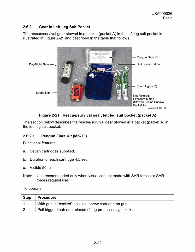
2.6.2 Gear in Left Leg Suit Pocket
The rescue/survival gear stowed in a packet (packet A) in the left leg suit pocket is illustrated in Figure 2-21 and described in the table that follows.
Figure 2-21. Rescue/survival gear, left leg suit pocket (packet A)
The section below describes the rescue/survival gear stowed in a packet (packet A) in the left leg suit pocket.
2.6.2.1 Pengun Flare Kit (MK-70)
Functional features:
a. Seven cartridges supplied.
b. Duration of each cartridge 4.5 sec.
c. Visible 50 mi.
Note: Use recommended only when visual contact made with SAR forces or SAR forces request use.
To operate:
Step Procedure 1 With gun in �cocked� position, screw cartridge on gun. 2 Pull trigger knob and release (firing produces slight kick).
USA009026 Basic
2-33
2.6.2.2 Two Chem Lights
Green 12-hr, Cyalume lightsticks.
To activate, bend to break glass vile and shake.
2.6.2.3 Day/Night Flare and Smoke Signal (MK-124)
Functional features:
a. Red smoke day; red flare night.
b. Duration: ~20 sec day/night.
c. Visibility: 7 mi day; 30 mi night.
d. Use gloves (flare and smoke generate heat).
Note: Use only when visual contact established with SAR forces or as directed by SAR forces.
To operate:
Step Procedure 1 Remove cover. 2 Holding flare away from raft, pull trigger out then down to fire.
Note: If smoke signal begins to flare, quickly dip in water.
2.6.2.4 Strobe Light
a. On/off switch.
b. Battery life 6 to 9 hr continuous operation; 18 hr intermittent.
c. Visible 50 mi.
USA009026 Basic
2-34
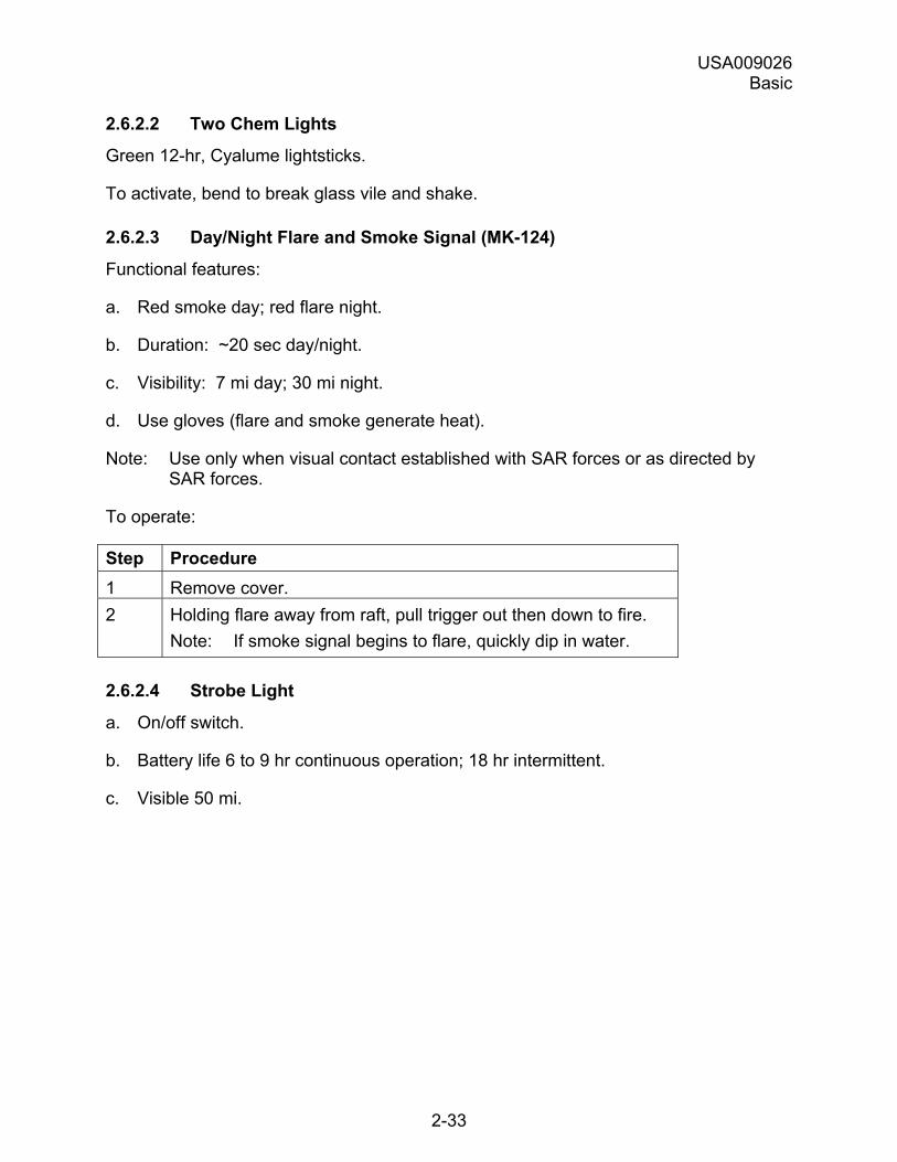
2.6.2.5 Exposure Mitten
Other mitten is in right leg pocket.
Figure 2-22. Exposure mittens
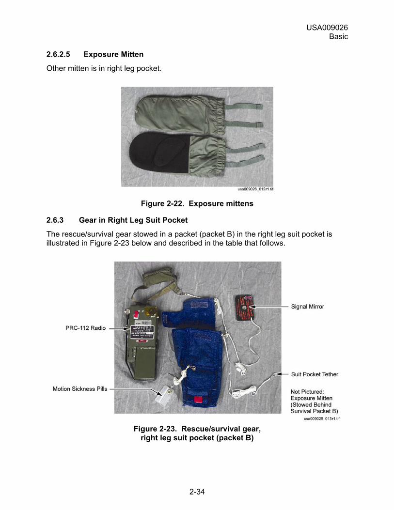
2.6.3 Gear in Right Leg Suit Pocket
The rescue/survival gear stowed in a packet (packet B) in the right leg suit pocket is illustrated in Figure 2-23 below and described in the table that follows.
Figure 2-23. Rescue/survival gear,
right leg suit pocket (packet B)
USA009026 Basic
2-35
The section below describes the rescue/survival gear stowed in a packet (packet B) in the right leg suit pocket:
2.6.3.1 Survival Radio
The radio, a PRC-112, has:
a. Transmit/receive capability.
b. Continuous beacon capability.
Battery life is 24 hr (duty cycle of 10% transmit and 90% receive).
An earphone and spare antenna are in a packet attached to the radio.
To operate the radio, follow the decal on the radio back. The decal procedures are shown below:
PRC-112 Radio Instructions
1. Extend SARSAT telescoping antenna, then disconnect wire antenna
2. Continue SARSAT beaconing
3. Standby for radio contact with SAR forces
4. Follow instructions from SAR forces
5. Return to 282.8 if contact with SAR forces lost
6. Verify SARSAT beacon tones with PRC-112 by momentarily listening to 243.0 (voice) and 121.5 (voice)
Additional Information
121.5 BCN
International emergency frequency (VHF/beacon)
121.5 International emergency frequency (VHF/voice) 243.0 BCN
Military emergency frequency (UHF/beacon)
243.0 Military emergency frequency (UHF/voice), DME supported 282.8 Primary SAR operations frequency (UHF/voice), DME supported A Secondary SAR operations (259.7) frequency (shuttle A/G) (UHF/voice), DME
supported B Backup SAR operations (236.0) frequency (UHF/voice), DME supported
USA009026 Basic
2-36
2.6.3.2 Signal Mirror
Visible 40 mi. Instructions for use displayed on back.
2.6.3.3 Two motion Sickness Pills
0.4 mg Scopolamine, 5 mg Dexedrine in each pill.
2.6.3.4 Exposure Mitten
Other mitten is in left leg pocket.
2.6.4 Shroudline Cutter/Knife
A shroudline cutter/knife is located in a small pocket on the upper left leg of the suit.
2.6.5 Gear, Parachute Harness
The parachute harness (Figure 2-13) includes the following emergency gear:
2.6.5.1 Life Preserver Unit
The LPU, attached to the harness, has the following features:
a. Horseshoe-shaped bladder that fits under the crewmember�s arms and around back.
b. Designed to keep an unconscious crewmember�s head out of the water.
c. Inflates with CO2 using two FLU-8 devices. FLU-8 are water activated or can be manually activated.
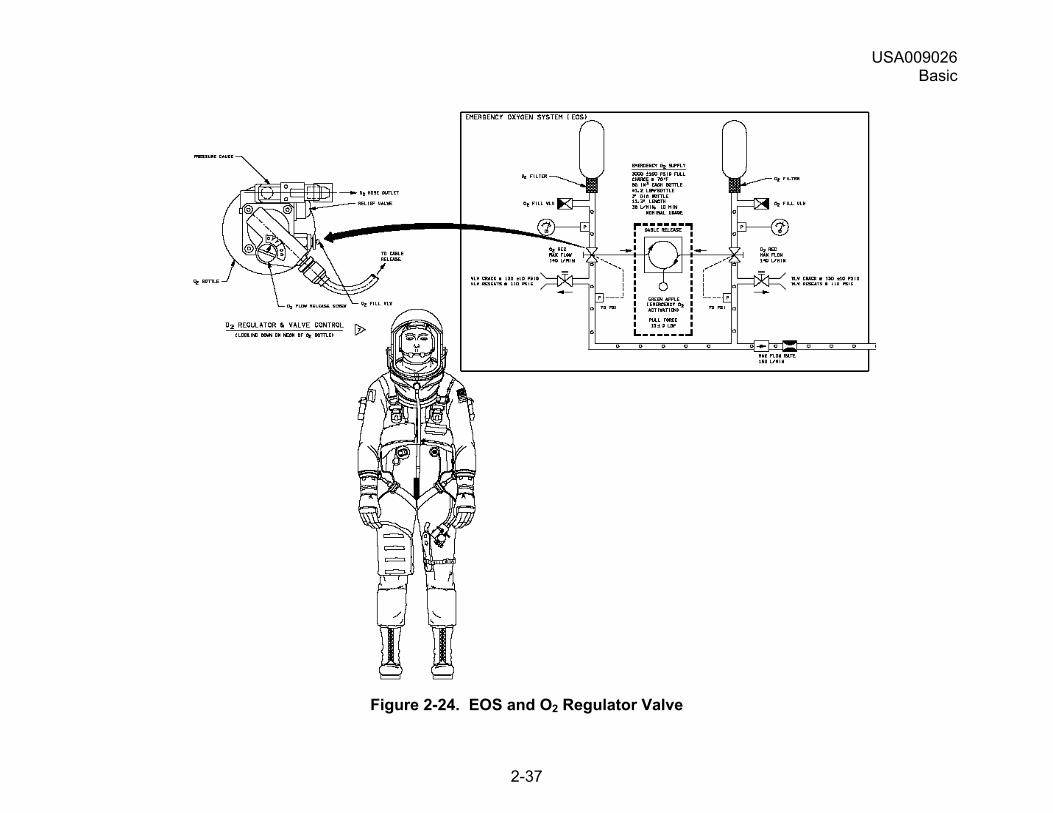
2.6.5.2 Emergency Oxygen System
Consists of two bottles of oxygen for use during emergency egress, which:
a. Are attached to the back of the harness.
b. Contain 120 in3 O2 at 3000 psi (381 liters usable O2).
c. Delivers O2, via reducer valves, at 70 psia.
d. At moderate level of exertion (38 liters/min of use), EOS will last 10 min at sea level and longer at high altitudes.
The figure below gives an overview of the EOS and the detail of the O2 regulator/valve:
USA009026 Basic
2-37
Figure 2-24. EOS and O2 Regulator Valve
USA009026 Basic
2-38
To activate the EOS:
Step Procedure 1 Lower and lock helmet visor.
Note: If helmet visor is opened, O2 will flow continuously into helmet. If orbiter O2 supply is not activated, EOS O2 will flow until bottles are depleted.
2 Pull EOS activation lanyard (�green apple�) on lower right front of harness. Note: There are two �clicks�:
1. The first disconnects the green apple from the snap keeper. 2. The second initiates O2 flow.
2.6.5.3 Carabiner
The carabiner (Figure 2-13), attached to right side of harness above the LPU, can be used to hoist a crewmember.
2.6.5.4 Emergency Drinking Water
The water pack containing emergency drinking water:
a. Is Velcroed to the rear of the harness between the EOS bottles.
b. Is tethered to the harness by a 2-foot tether.
c. Has 2 liters of water contained in 16 packets.
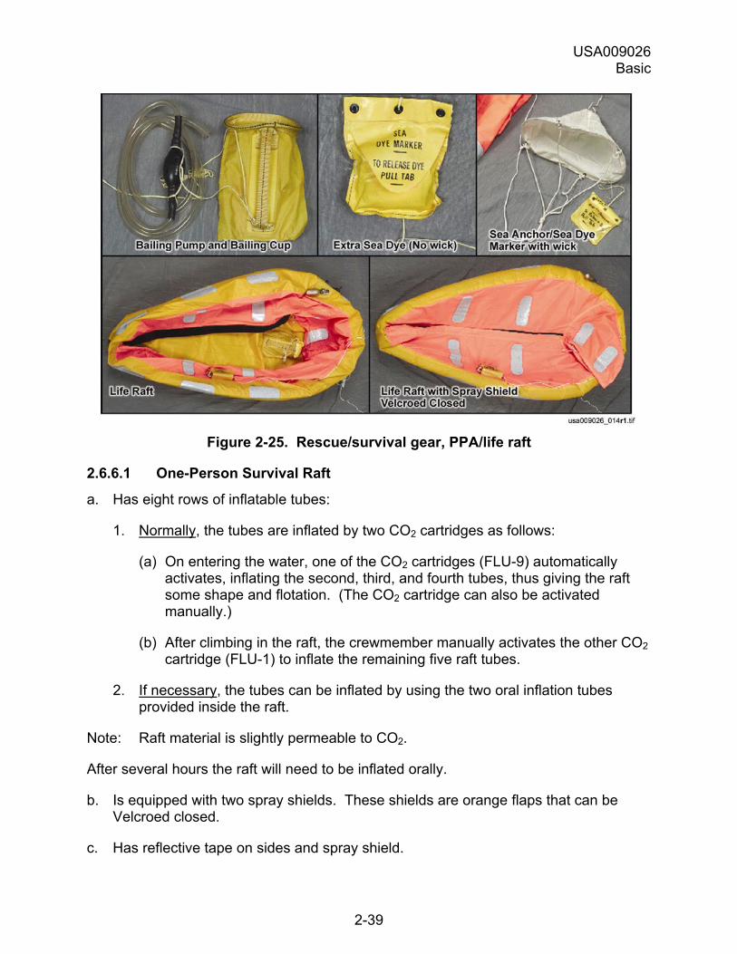
2.6.6 Gear in PPA/Life Raft
The rescue/survival gear stowed in the life raft, which is contained in the PPA, is illustrated in Figure 2-25 below and described in the following section.
USA009026 Basic
2-39
Figure 2-25. Rescue/survival gear, PPA/life raft
2.6.6.1 One-Person Survival Raft
a. Has eight rows of inflatable tubes:
1. Normally, the tubes are inflated by two CO2 cartridges as follows:
(a) On entering the water, one of the CO2 cartridges (FLU-9) automatically activates, inflating the second, third, and fourth tubes, thus giving the raft some shape and flotation. (The CO2 cartridge can also be activated manually.)
(b) After climbing in the raft, the crewmember manually activates the other CO2 cartridge (FLU-1) to inflate the remaining five raft tubes.
2. If necessary, the tubes can be inflated by using the two oral inflation tubes provided inside the raft.
Note: Raft material is slightly permeable to CO2.
After several hours the raft will need to be inflated orally.
b. Is equipped with two spray shields. These shields are orange flaps that can be Velcroed closed.
c. Has reflective tape on sides and spray shield.
USA009026 Basic
2-40
d. Is tethered to PPA remnant (the part that remains on crewmember) by 12-foot Kevlar tether.
e. Has bailing cup, bailing pump, and additional sea dye marker tethered inside the raft on the right side.
2.6.6.2 SARSAT Personal Locator Beacon
a. Flexible antenna loops around the back of the spray shield.
b. Extendable, rigid antenna manually deployed for better signal transmission.
c. On/off switch, battery life approximately 24 hours.
d. Beacon automatically activates upon parachute deployment, transmitting on the following frequencies:
121.5 International emergency 243.0 Military emergency 406.0 Satellite SAR
2.6.6.3 Sea Anchor/Sea Dye Marker
a. Tethered to outside of raft by a 12-foot tether.
b. The anchor is usually allowed to be untied by wave action.
c. Sea dye package that is designed to automatically wick dye when placed in the water.
d. Sea dye produces a green fluorescent slick highly visible by SAR forces.
Note: The dye dissipates quicker in rough conditions.
2.6.6.4 Additional Packet of Sea Dye
a. Tethered to inside of raft on right side.
b. Packet is sealed without wick.
c. Open packet when requested by SAR forces.
USA009026 Basic
2-41
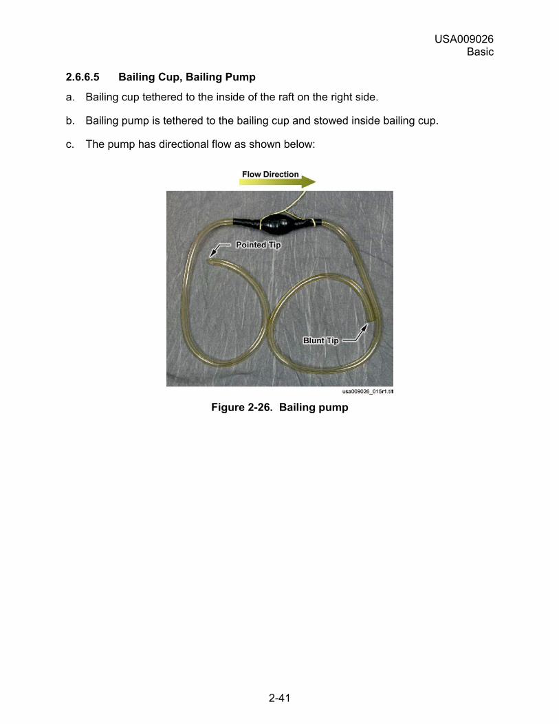
2.6.6.5 Bailing Cup, Bailing Pump
a. Bailing cup tethered to the inside of the raft on the right side.
b. Bailing pump is tethered to the bailing cup and stowed inside bailing cup.
c. The pump has directional flow as shown below:
Figure 2-26. Bailing pump
USA009026 Basic
3-1
3.0 ORBITER HARDWARE
3.1 OVERVIEW
3.1.1 Introduction
Crew escape hardware has been built into the orbiter that facilitates quick and safe crew egress/escape in an emergency. This hardware includes:
a. Crew seats.
b. Emergency egress net (trampoline), a platform for prelaunch egress.
c. The escape pole, for in-flight bailout.
d. The escape slide, for postlanding egress from the side hatch.
e. The Window 8 escape panel, secondary postlanding egress path in the event of total side hatch failure.
f. The descent control devices (Sky Genie), for postlanding egress in the event of complete slide failure.
g. The side hatch pyrotechnic jettison system and cabin vent system.
3.1.2 Purpose
This chapter describes the components, operational features, and operation of orbiter crew escape hardware.
3.1.3 Objectives
After completing this chapter, you will be able to identify:
a. Components of the crew seats
b. Components of the emergency egress net (trampoline).
c. Components of the escape pole and the steps in deploying and using the pole for bailout.
d. Components of the emergency egress slide system and the steps in using the system with:
1. The side hatch on (hatch opened normally).
2. The side hatch off (hatch jettisoned).
e. Components of the Window 8 escape panel and the steps in opening it.
USA009026 Basic
3-2
f. Components of the descent control device (Sky Genie) and the steps in using it postlanding to descend from the orbiter through:
1. The side hatch (primary route).
2. The Window 8 escape panel (secondary route).
g. Components of the side hatch and the steps in opening the hatch normally and by jettisoning.
In This Chapter
Sections describe crew escape orbiter hardware as follows:
Section Page Crew Seats 3-2 Emergency Egress Net (Trampoline) 3-7 Side Hatch 3-12 Window 8 Escape Panel 3-18 Descent Control Device (Sky Genie) 3-27 Escape Pole 3-31 Emergency Egress Slide System 3-34
3.2 CREW SEATS
3.2.1 Description
Two types of seats are provided for crew positioning and restraint during all phases of flight. Each seat accommodates a fully suited crewmember, cooling unit, and FDF stowage bag. The seats can also secure oxygen hoses, communications, and power cables for launch and entry.
USA009026 Basic
3-3
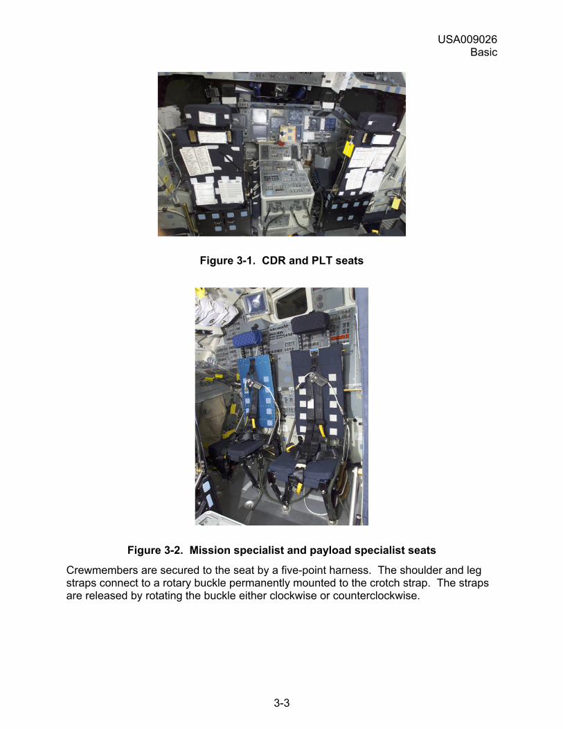
Figure 3-1. CDR and PLT seats
Figure 3-2. Mission specialist and payload specialist seats
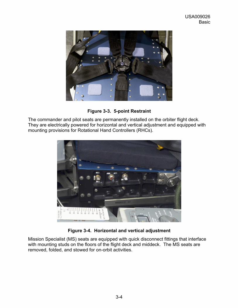
Crewmembers are secured to the seat by a five-point harness. The shoulder and leg straps connect to a rotary buckle permanently mounted to the crotch strap. The straps are released by rotating the buckle either clockwise or counterclockwise.
USA009026 Basic
3-4
Figure 3-3. 5-point Restraint
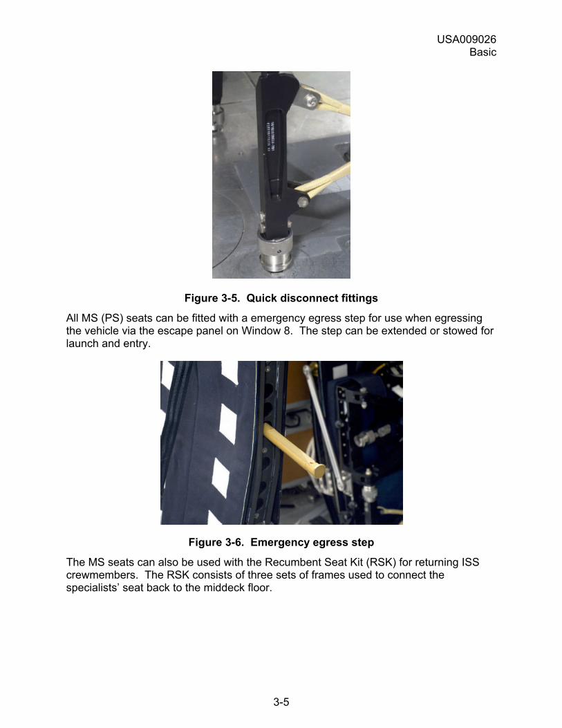
The commander and pilot seats are permanently installed on the orbiter flight deck. They are electrically powered for horizontal and vertical adjustment and equipped with mounting provisions for Rotational Hand Controllers (RHCs).
Figure 3-4. Horizontal and vertical adjustment
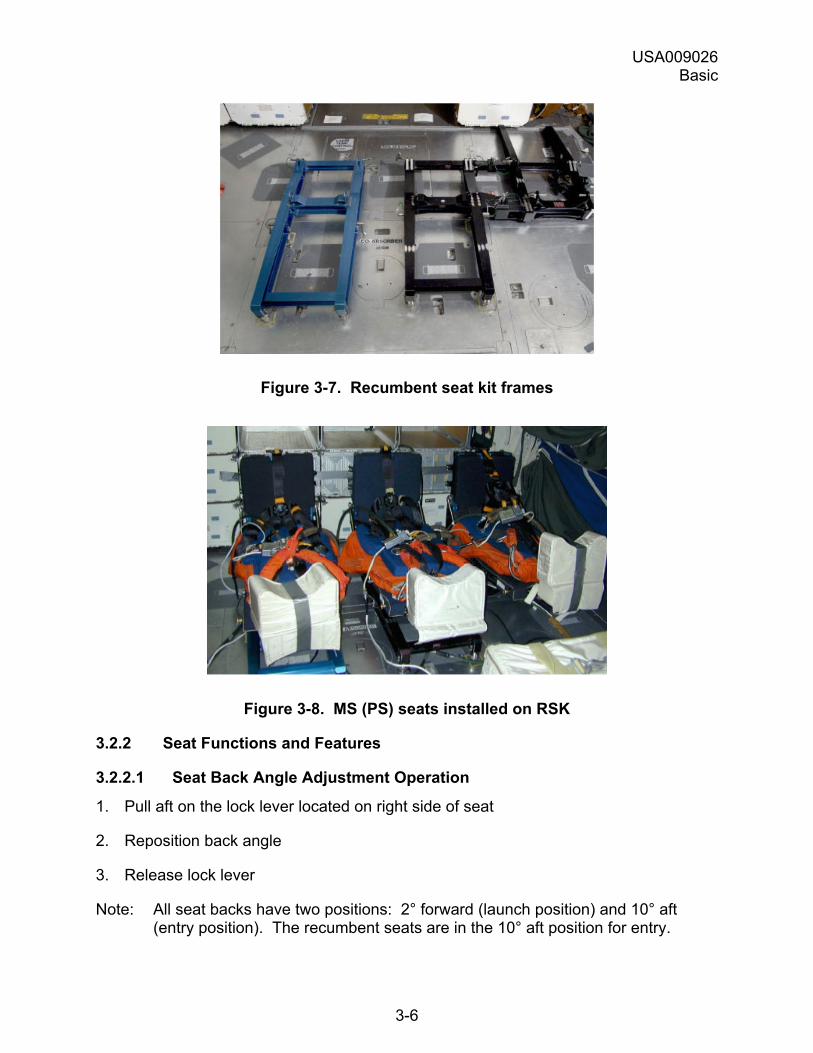
Mission Specialist (MS) seats are equipped with quick disconnect fittings that interface with mounting studs on the floors of the flight deck and middeck. The MS seats are removed, folded, and stowed for on-orbit activities.
USA009026 Basic
3-5
Figure 3-5. Quick disconnect fittings
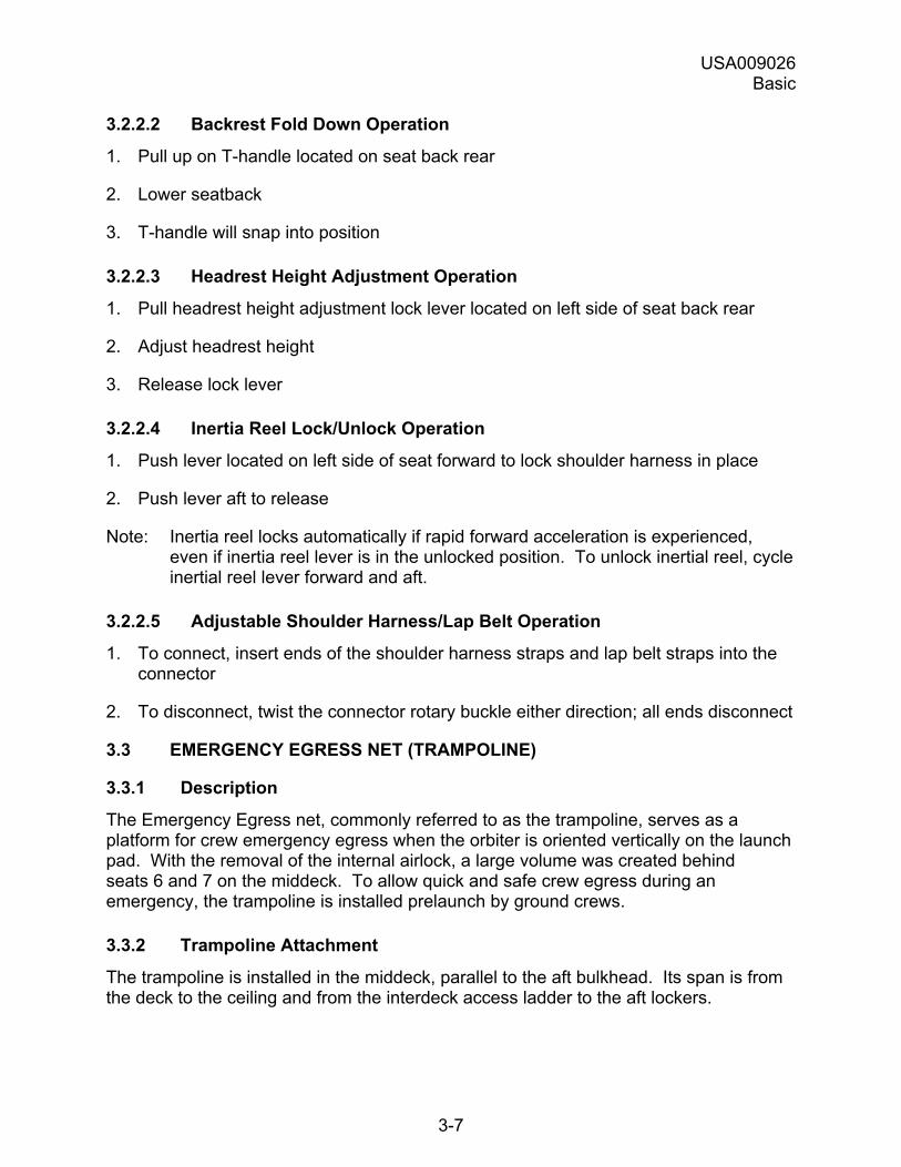
All MS (PS) seats can be fitted with a emergency egress step for use when egressing the vehicle via the escape panel on Window 8. The step can be extended or stowed for launch and entry.
Figure 3-6. Emergency egress step
The MS seats can also be used with the Recumbent Seat Kit (RSK) for returning ISS crewmembers. The RSK consists of three sets of frames used to connect the specialists� seat back to the middeck floor.
USA009026 Basic
3-6
Figure 3-7. Recumbent seat kit frames
Figure 3-8. MS (PS) seats installed on RSK
3.2.2 Seat Functions and Features
3.2.2.1 Seat Back Angle Adjustment Operation
1. Pull aft on the lock lever located on right side of seat
2. Reposition back angle
3. Release lock lever
Note: All seat backs have two positions: 2° forward (launch position) and 10° aft (entry position). The recumbent seats are in the 10° aft position for entry.
USA009026 Basic
3-7
3.2.2.2 Backrest Fold Down Operation
1. Pull up on T-handle located on seat back rear
2. Lower seatback
3. T-handle will snap into position
3.2.2.3 Headrest Height Adjustment Operation
1. Pull headrest height adjustment lock lever located on left side of seat back rear
2. Adjust headrest height
3. Release lock lever
3.2.2.4 Inertia Reel Lock/Unlock Operation
1. Push lever located on left side of seat forward to lock shoulder harness in place
2. Push lever aft to release
Note: Inertia reel locks automatically if rapid forward acceleration is experienced, even if inertia reel lever is in the unlocked position. To unlock inertial reel, cycle inertial reel lever forward and aft.
3.2.2.5 Adjustable Shoulder Harness/Lap Belt Operation
1. To connect, insert ends of the shoulder harness straps and lap belt straps into the connector
2. To disconnect, twist the connector rotary buckle either direction; all ends disconnect
3.3 EMERGENCY EGRESS NET (TRAMPOLINE)
3.3.1 Description
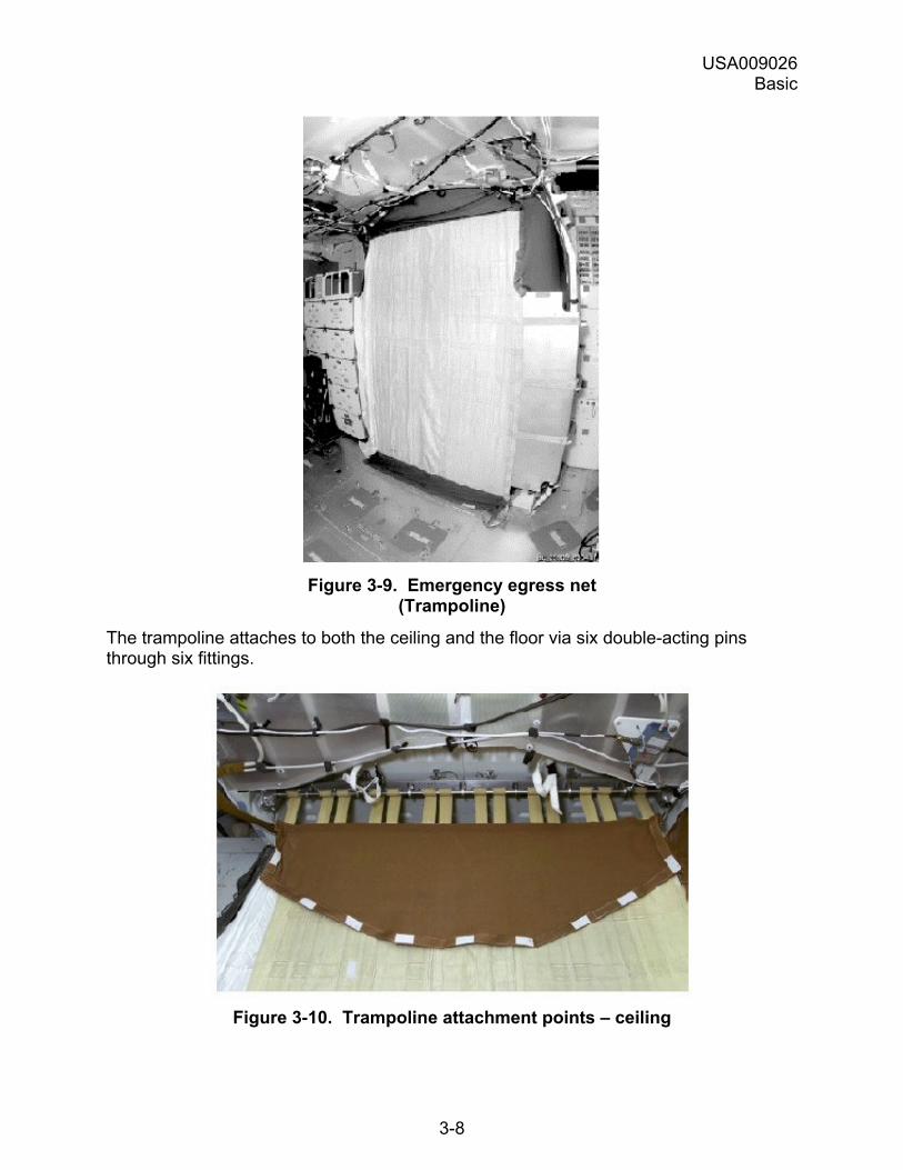
The Emergency Egress net, commonly referred to as the trampoline, serves as a platform for crew emergency egress when the orbiter is oriented vertically on the launch pad. With the removal of the internal airlock, a large volume was created behind seats 6 and 7 on the middeck. To allow quick and safe crew egress during an emergency, the trampoline is installed prelaunch by ground crews.
3.3.2 Trampoline Attachment
The trampoline is installed in the middeck, parallel to the aft bulkhead. Its span is from the deck to the ceiling and from the interdeck access ladder to the aft lockers.
USA009026 Basic
3-8
Figure 3-9. Emergency egress net
(Trampoline)
The trampoline attaches to both the ceiling and the floor via six double-acting pins through six fittings.
Figure 3-10. Trampoline attachment points � ceiling
USA009026 Basic
3-9
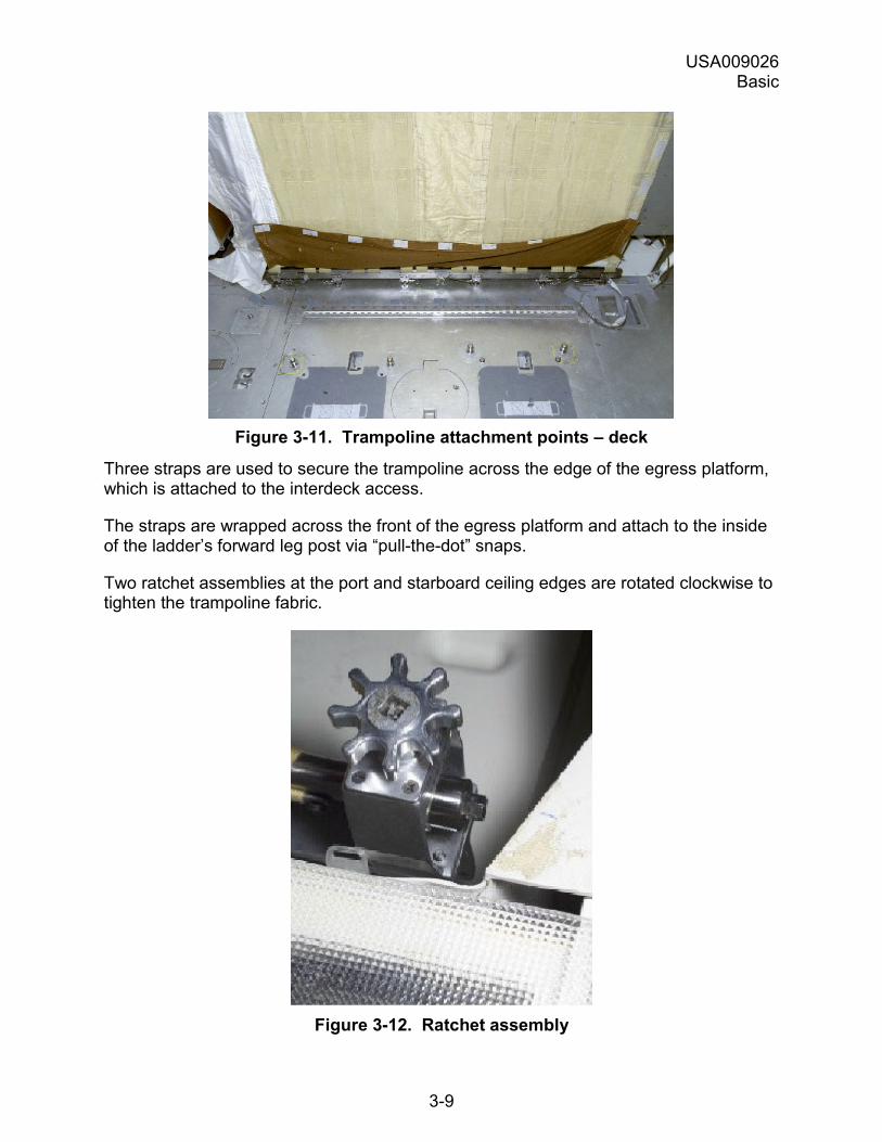
Figure 3-11. Trampoline attachment points � deck
Three straps are used to secure the trampoline across the edge of the egress platform, which is attached to the interdeck access.
The straps are wrapped across the front of the egress platform and attach to the inside of the ladder�s forward leg post via �pull-the-dot� snaps.
Two ratchet assemblies at the port and starboard ceiling edges are rotated clockwise to tighten the trampoline fabric.
Figure 3-12. Ratchet assembly
USA009026 Basic
3-10
3.3.3 Closeout Nets
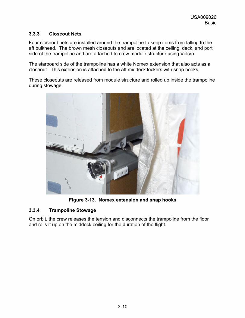
Four closeout nets are installed around the trampoline to keep items from falling to the aft bulkhead. The brown mesh closeouts and are located at the ceiling, deck, and port side of the trampoline and are attached to crew module structure using Velcro.
The starboard side of the trampoline has a white Nomex extension that also acts as a closeout. This extension is attached to the aft middeck lockers with snap hooks.
These closeouts are released from module structure and rolled up inside the trampoline during stowage.
Figure 3-13. Nomex extension and snap hooks
3.3.4 Trampoline Stowage
On orbit, the crew releases the tension and disconnects the trampoline from the floor and rolls it up on the middeck ceiling for the duration of the flight.
USA009026 Basic
3-11
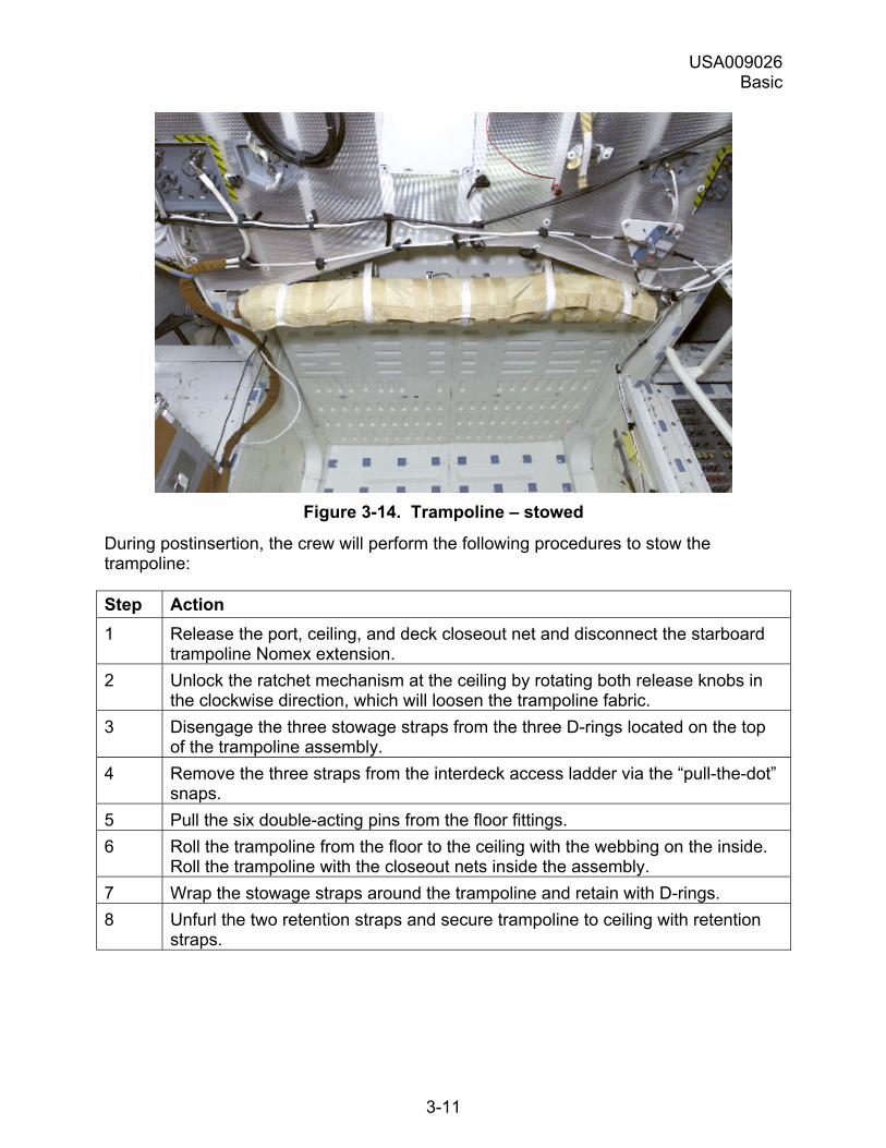
Figure 3-14. Trampoline � stowed
During postinsertion, the crew will perform the following procedures to stow the trampoline:
Step Action 1 Release the port, ceiling, and deck closeout net and disconnect the starboard
trampoline Nomex extension. 2 Unlock the ratchet mechanism at the ceiling by rotating both release knobs in
the clockwise direction, which will loosen the trampoline fabric. 3 Disengage the three stowage straps from the three D-rings located on the top
of the trampoline assembly. 4 Remove the three straps from the interdeck access ladder via the �pull-the-dot�
snaps. 5 Pull the six double-acting pins from the floor fittings. 6 Roll the trampoline from the floor to the ceiling with the webbing on the inside.
Roll the trampoline with the closeout nets inside the assembly. 7 Wrap the stowage straps around the trampoline and retain with D-rings. 8 Unfurl the two retention straps and secure trampoline to ceiling with retention
straps.
USA009026 Basic
3-12
3.4 SIDE HATCH
3.4.1 Introduction
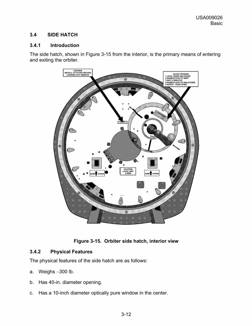
The side hatch, shown in Figure 3-15 from the interior, is the primary means of entering and exiting the orbiter.
Figure 3-15. Orbiter side hatch, interior view
3.4.2 Physical Features
The physical features of the side hatch are as follows:
a. Weighs ∼300 lb.
b. Has 40-in. diameter opening.
c. Has a 10-inch diameter optically pure window in the center.
USA009026 Basic
3-13
d. Is attached to crew cabin structure by hinges and secured closed by 18 hatches.
e. Has two pressure seals.
3.4.3 Functional Features
The functional features of side hatch mechanisms are as follows:
a. Force required to operate the hatch mechanisms:
1. Lock lever: 6 to 13 lbf to unlock.
2. Hatch handle: ~16 lbf to rotate, 25 lbf to overcome vent position detent.
b. A hydraulic attenuator controls the rate of hatch opening.
c. Hatch opens outwardly 90° (down when vehicle is in horizontal position).
3.4.4 Normal Side Hatch Opening
During normal operations, the flight crew does not need to operate the side hatch because:
a. Prelaunch, the closeout crew closes and seals the hatch.
b. Postflight, the convoy crew opens the hatch.
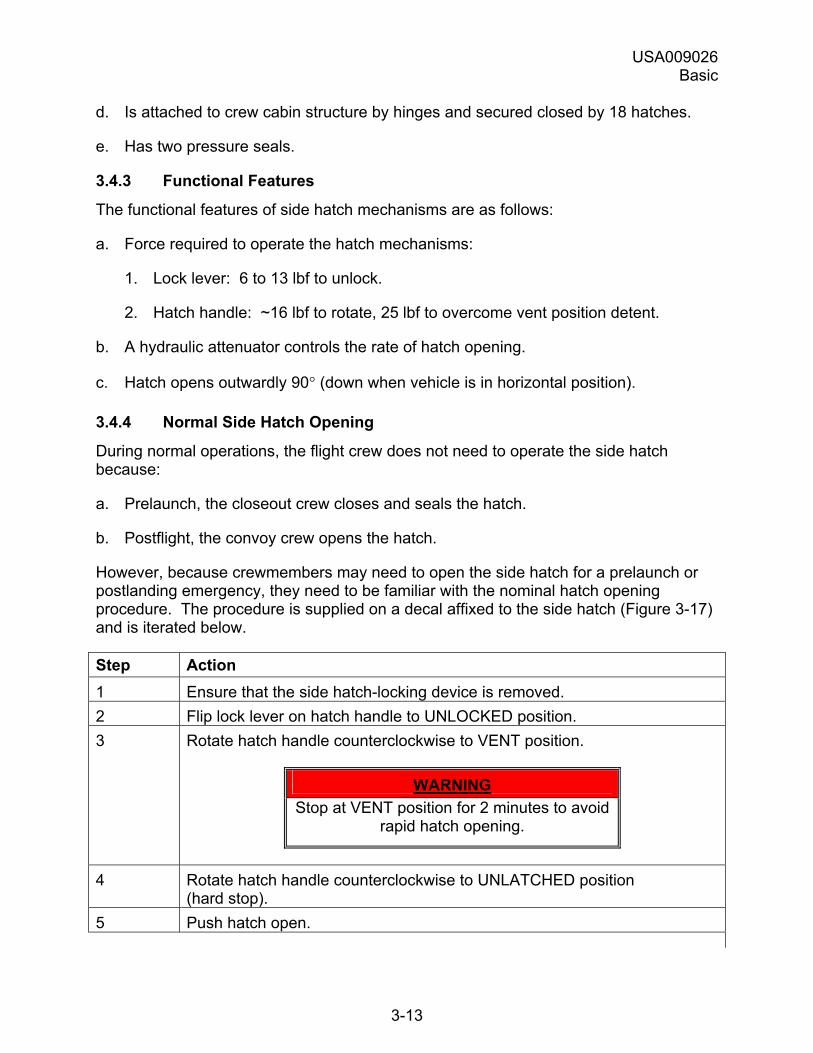
However, because crewmembers may need to open the side hatch for a prelaunch or postlanding emergency, they need to be familiar with the nominal hatch opening procedure. The procedure is supplied on a decal affixed to the side hatch (Figure 3-17) and is iterated below.
Step Action 1 Ensure that the side hatch-locking device is removed. 2 Flip lock lever on hatch handle to UNLOCKED position. 3 Rotate hatch handle counterclockwise to VENT position.
WARNING Stop at VENT position for 2 minutes to avoid
rapid hatch opening.
4 Rotate hatch handle counterclockwise to UNLATCHED position (hard stop).
5 Push hatch open.
USA009026 Basic
3-14
3.4.5 Depress, Hatch Jettison
Both the depressurization and hatch jettison are accomplished through a pyrotechnic system that includes the following components:
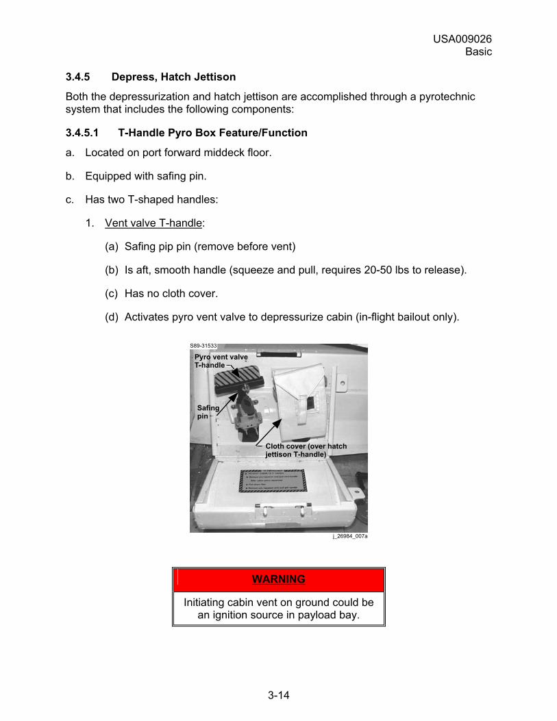
3.4.5.1 T-Handle Pyro Box Feature/Function
a. Located on port forward middeck floor.
b. Equipped with safing pin.
c. Has two T-shaped handles:
1. Vent valve T-handle:
(a) Safing pip pin (remove before vent)
(b) Is aft, smooth handle (squeeze and pull, requires 20-50 lbs to release).
(c) Has no cloth cover.
(d) Activates pyro vent valve to depressurize cabin (in-flight bailout only).
Safingpin
Pyro vent valveT-handle
S89-31533
Cloth cover (over hatchjettison T-handle)
j_26984_007a
WARNING
Initiating cabin vent on ground could be an ignition source in payload bay.
USA009026 Basic
3-15
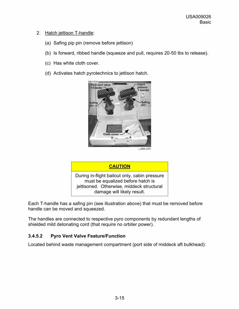
2. Hatch jettison T-handle:
(a) Safing pip pin (remove before jettison)
(b) Is forward, ribbed handle (squeeze and pull, requires 20-50 lbs to release).
(c) Has white cloth cover.
(d) Activates hatch pyrotechnics to jettison hatch.
SafingpinSafingpin
Cloth cover
SafingpinSafingpin
j_26984_007b
S89-31534Pyro vent valveT-handlePyro vent valveT-handle
HatchjettisonT-handle
HatchjettisonT-handle
CAUTION
During in-flight bailout only, cabin pressure must be equalized before hatch is
jettisoned. Otherwise, middeck structural damage will likely result.
Each T-handle has a safing pin (see illustration above) that must be removed before handle can be moved and squeezed.
The handles are connected to respective pyro components by redundant lengths of shielded mild detonating cord (that require no orbiter power).
3.4.5.2 Pyro Vent Valve Feature/Function
Located behind waste management compartment (port side of middeck aft bulkhead):
USA009026 Basic
3-16
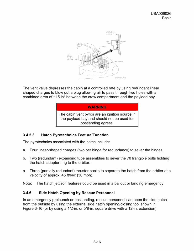
The vent valve depresses the cabin at a controlled rate by using redundant linear shaped charges to blow out a plug allowing air to pass through two holes with a combined area of ~15 in2 between the crew compartment and the payload bay.
WARNING
The cabin vent pyros are an ignition source in the payload bay and should not be used for
postlanding egress.
3.4.5.3 Hatch Pyrotechnics Feature/Function
The pyrotechnics associated with the hatch include:
a. Four linear-shaped charges (two per hinge for redundancy) to sever the hinges.
b. Two (redundant) expanding tube assemblies to sever the 70 frangible bolts holding the hatch adapter ring to the orbiter.
c. Three (partially redundant) thruster packs to separate the hatch from the orbiter at a velocity of approx. 45 ft/sec (30 mph).
Note: The hatch jettison features could be used in a bailout or landing emergency.
3.4.6 Side Hatch Opening by Rescue Personnel
In an emergency prelaunch or postlanding, rescue personnel can open the side hatch from the outside by using the external side hatch opening/closing tool shown in Figure 3-16 (or by using a 1/2-in. or 5/8-in. square drive with a 12-in. extension).
USA009026 Basic
3-17
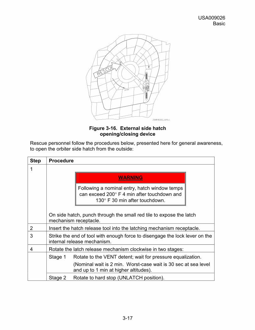
Figure 3-16. External side hatch
opening/closing device
Rescue personnel follow the procedures below, presented here for general awareness, to open the orbiter side hatch from the outside:
Step Procedure 1
WARNING
Following a nominal entry, hatch window temps can exceed 200° F 4 min after touchdown and
130° F 30 min after touchdown.
On side hatch, punch through the small red tile to expose the latch mechanism receptacle.
2 Insert the hatch release tool into the latching mechanism receptacle. 3 Strike the end of tool with enough force to disengage the lock lever on the
internal release mechanism. 4 Rotate the latch release mechanism clockwise in two stages: Stage 1 Rotate to the VENT detent; wait for pressure equalization.
(Nominal wait is 2 min. Worst-case wait is 30 sec at sea level and up to 1 min at higher altitudes).
Stage 2 Rotate to hard stop (UNLATCH position).
USA009026 Basic
3-18
Step Procedure
WARNING
Stand clear when opening the hatch. The side hatch weighs 300 lb. Positive cabin pressure can cause the hatch to initially open rapidly.
5 If necessary, pull or pry the hatch open from the top (hatch opening is attenuated).
3.5 WINDOW 8 ESCAPE PANEL
3.5.1 Introduction
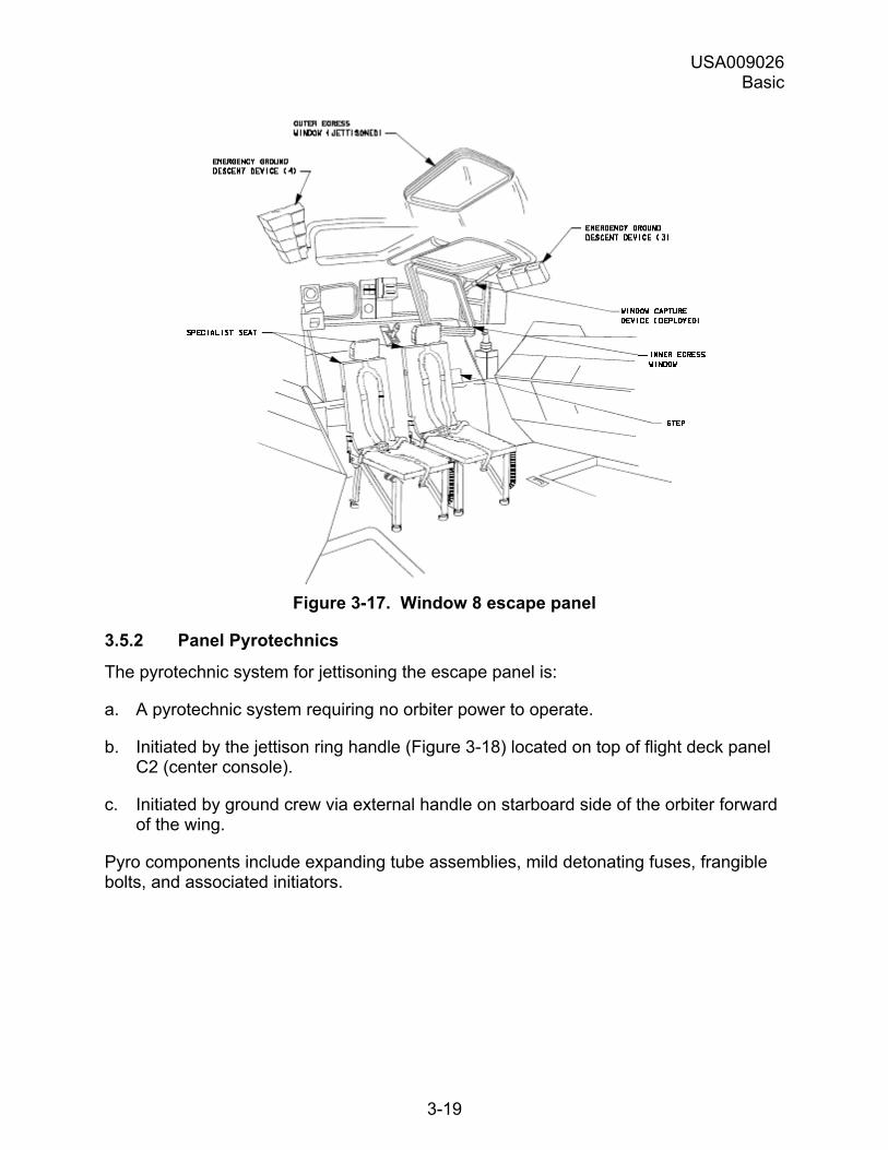
Postlanding, if emergency egress through the side hatch is impossible, the crew uses the secondary route, which is via the Window 8 escape panel (Figure 3-17).
To use this secondary route, crewmembers
a. Jettison the Window 8 escape panel using the panel pyrotechnic system as described in subsection �Escape panel jettison.�
b. Attach to a sky genie (see next section).
c. Climb out Window 8 using MS2�s seat.
d. Descend the starboard side of the orbiter (Can descend on port side, but starboard side is preferable to avoid side hatch pyrotechnics).
USA009026 Basic
3-19
Figure 3-17. Window 8 escape panel
3.5.2 Panel Pyrotechnics
The pyrotechnic system for jettisoning the escape panel is:
a. A pyrotechnic system requiring no orbiter power to operate.
b. Initiated by the jettison ring handle (Figure 3-18) located on top of flight deck panel C2 (center console).
c. Initiated by ground crew via external handle on starboard side of the orbiter forward of the wing.
Pyro components include expanding tube assemblies, mild detonating fuses, frangible bolts, and associated initiators.
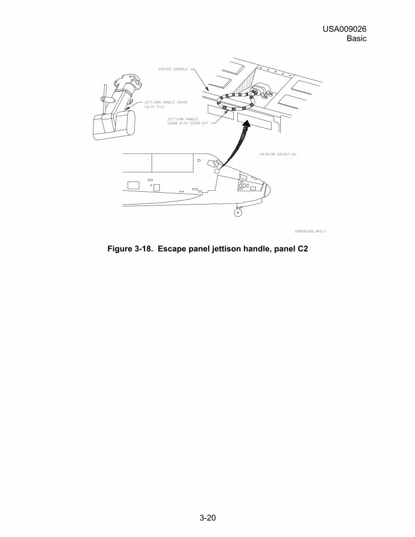
USA009026 Basic
3-20
Figure 3-18. Escape panel jettison handle, panel C2
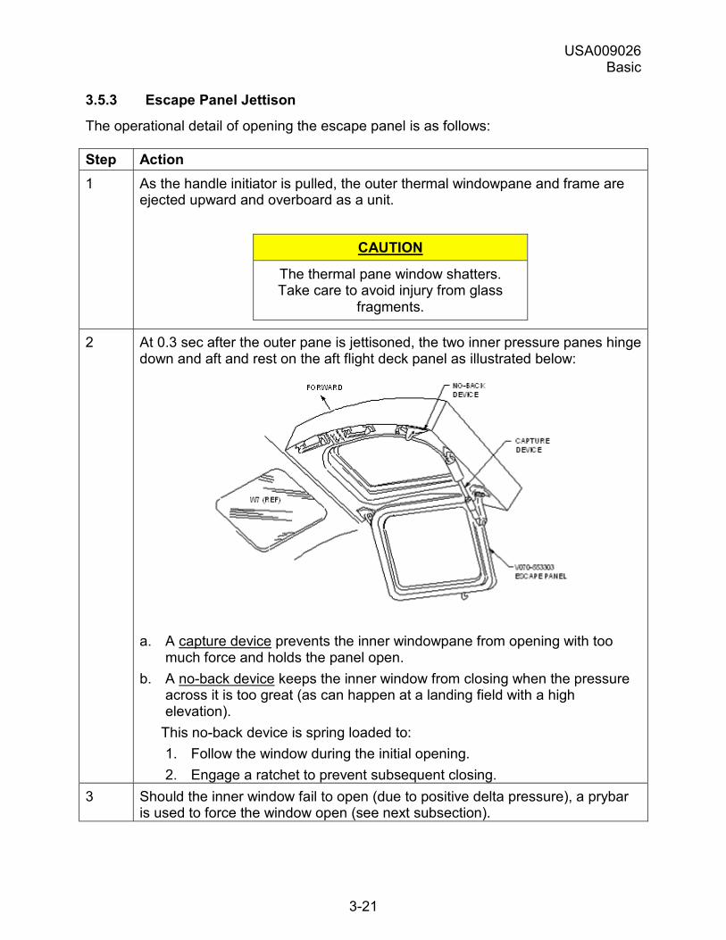
USA009026 Basic
3-21
3.5.3 Escape Panel Jettison
The operational detail of opening the escape panel is as follows:
Step Action 1 As the handle initiator is pulled, the outer thermal windowpane and frame are
ejected upward and overboard as a unit.
CAUTION
The thermal pane window shatters. Take care to avoid injury from glass
fragments.
2 At 0.3 sec after the outer pane is jettisoned, the two inner pressure panes hinge down and aft and rest on the aft flight deck panel as illustrated below:
a. A capture device prevents the inner windowpane from opening with too much force and holds the panel open.
b. A no-back device keeps the inner window from closing when the pressure across it is too great (as can happen at a landing field with a high elevation).
This no-back device is spring loaded to: 1. Follow the window during the initial opening. 2. Engage a ratchet to prevent subsequent closing.
3 Should the inner window fail to open (due to positive delta pressure), a prybar is used to force the window open (see next subsection).
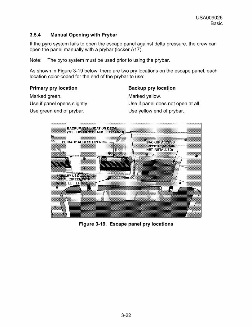
USA009026 Basic
3-22
3.5.4 Manual Opening with Prybar
If the pyro system fails to open the escape panel against delta pressure, the crew can open the panel manually with a prybar (locker A17).
Note: The pyro system must be used prior to using the prybar.
As shown in Figure 3-19 below, there are two pry locations on the escape panel, each location color-coded for the end of the prybar to use:
Primary pry location Backup pry location Marked green. Marked yellow. Use if panel opens slightly. Use if panel does not open at all. Use green end of prybar. Use yellow end of prybar.
Figure 3-19. Escape panel pry locations
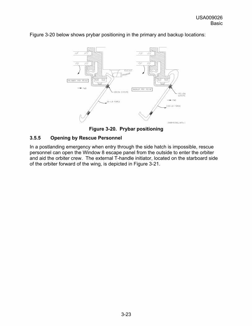
USA009026 Basic
3-23
Figure 3-20 below shows prybar positioning in the primary and backup locations:
Figure 3-20. Prybar positioning
3.5.5 Opening by Rescue Personnel
In a postlanding emergency when entry through the side hatch is impossible, rescue personnel can open the Window 8 escape panel from the outside to enter the orbiter and aid the orbiter crew. The external T-handle initiator, located on the starboard side of the orbiter forward of the wing, is depicted in Figure 3-21.
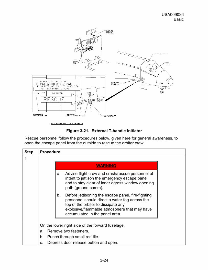
USA009026 Basic
3-24
Figure 3-21. External T-handle initiator
Rescue personnel follow the procedures below, given here for general awareness, to open the escape panel from the outside to rescue the orbiter crew.
Step Procedure 1
WARNING
a. Advise flight crew and crash/rescue personnel of intent to jettison the emergency escape panel and to stay clear of inner egress window opening path (ground comm).
b. Before jettisoning the escape panel, fire-fighting personnel should direct a water fog across the top of the orbiter to dissipate any explosive/flammable atmosphere that may have accumulated in the panel area.
On the lower right side of the forward fuselage: a. Remove two fasteners. b. Punch through small red tile. c. Depress door release button and open.
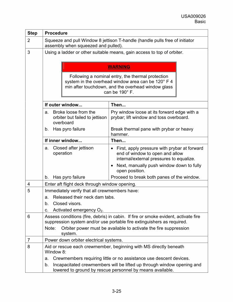
USA009026 Basic
3-25
Step Procedure 2 Squeeze and pull Window 8 jettison T-handle (handle pulls free of initiator
assembly when squeezed and pulled). 3 Using a ladder or other suitable means, gain access to top of orbiter.
WARNING
Following a nominal entry, the thermal protection system in the overhead window area can be 120° F 4 min after touchdown, and the overhead window glass
can be 190° F.
If outer window... Then... a. Broke loose from the
orbiter but failed to jettison overboard
Pry window loose at its forward edge with a prybar; lift window and toss overboard.
b. Has pyro failure Break thermal pane with prybar or heavy hammer.
If inner window... Then... a. Closed after jettison
operation • First, apply pressure with prybar at forward
end of window to open and allow internal/external pressures to equalize.
• Next, manually push window down to fully open position.
b. Has pyro failure Proceed to break both panes of the window. 4 Enter aft flight deck through window opening. 5 Immediately verify that all crewmembers have:
a. Released their neck dam tabs. b. Closed visors. c. Activated emergency O2.
6 Assess conditions (fire, debris) in cabin. If fire or smoke evident, activate fire suppression system and/or use portable fire extinguishers as required. Note: Orbiter power must be available to activate the fire suppression
system. 7 Power down orbiter electrical systems. 8 Aid or rescue each crewmember, beginning with MS directly beneath
Window 8: a. Crewmembers requiring little or no assistance use descent devices. b. Incapacitated crewmembers will be lifted up through window opening and
lowered to ground by rescue personnel by means available.
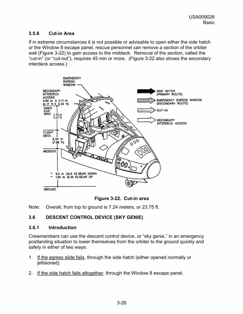
USA009026 Basic
3-26
3.5.6 Cut-in Area
If in extreme circumstances it is not possible or advisable to open either the side hatch or the Window 8 escape panel, rescue personnel can remove a section of the orbiter wall (Figure 3-22) to gain access to the middeck. Removal of the section, called the �cut-in� (or �cut-out�), requires 45 min or more. (Figure 3-22 also shows the secondary interdeck access.)
Figure 3-22. Cut-in area
Note: Overall, from top to ground is 7.24 meters, or 23.75 ft.
3.6 DESCENT CONTROL DEVICE (SKY GENIE)
3.6.1 Introduction
Crewmembers can use the descent control device, or �sky genie,� in an emergency postlanding situation to lower themselves from the orbiter to the ground quickly and safely in either of two ways:
1. If the egress slide fails, through the side hatch (either opened normally or jettisoned).
2. If the side hatch fails altogether, through the Window 8 escape panel.
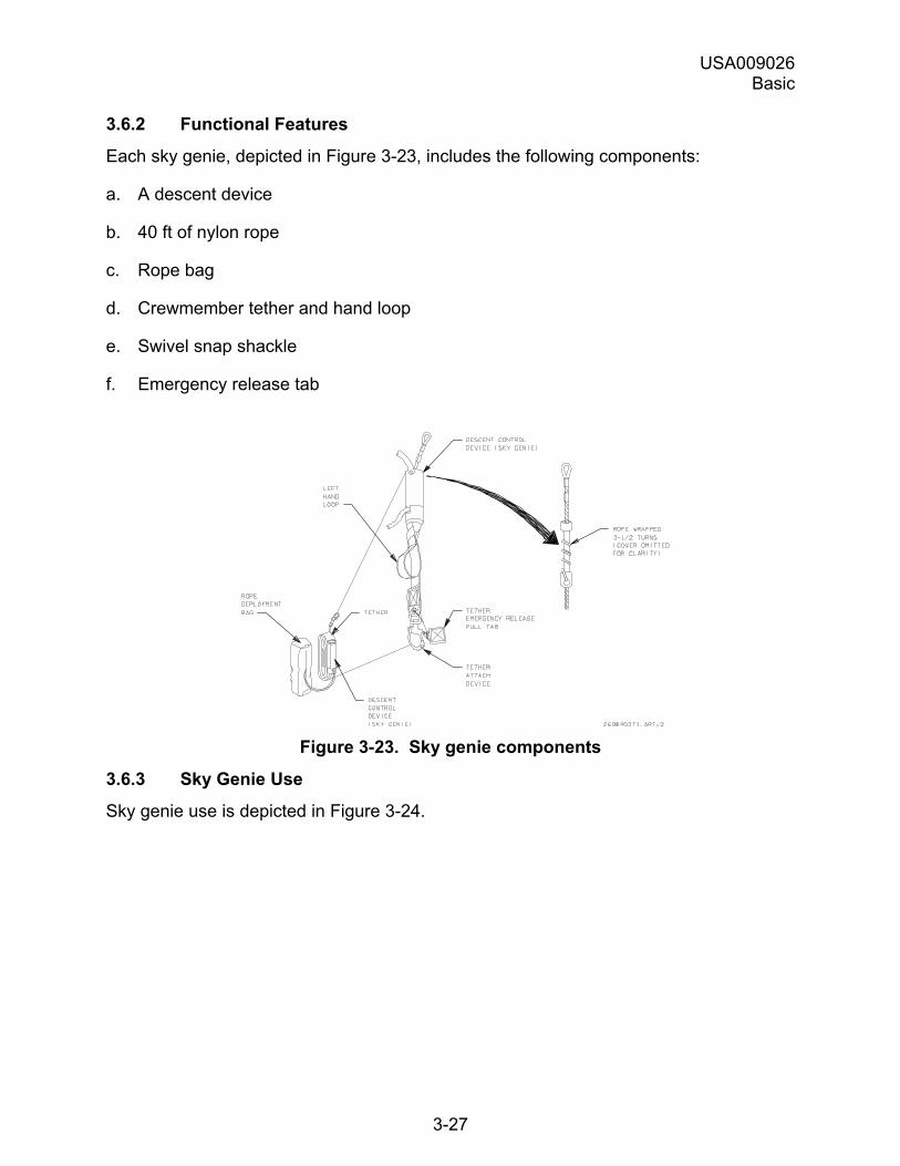
USA009026 Basic
3-27
3.6.2 Functional Features
Each sky genie, depicted in Figure 3-23, includes the following components:
a. A descent device
b. 40 ft of nylon rope
c. Rope bag
d. Crewmember tether and hand loop
e. Swivel snap shackle
f. Emergency release tab
Figure 3-23. Sky genie components
3.6.3 Sky Genie Use
Sky genie use is depicted in Figure 3-24.
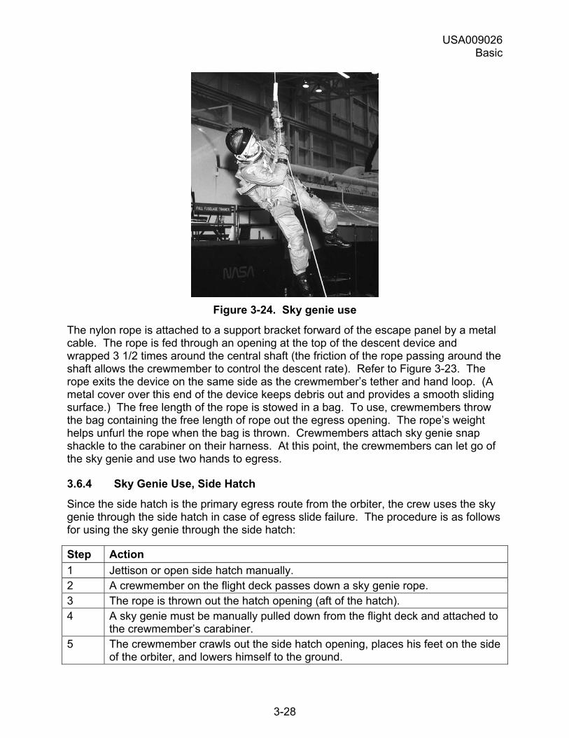
USA009026 Basic
3-28
Figure 3-24. Sky genie use
The nylon rope is attached to a support bracket forward of the escape panel by a metal cable. The rope is fed through an opening at the top of the descent device and wrapped 3 1/2 times around the central shaft (the friction of the rope passing around the shaft allows the crewmember to control the descent rate). Refer to Figure 3-23. The rope exits the device on the same side as the crewmember�s tether and hand loop. (A metal cover over this end of the device keeps debris out and provides a smooth sliding surface.) The free length of the rope is stowed in a bag. To use, crewmembers throw the bag containing the free length of rope out the egress opening. The rope�s weight helps unfurl the rope when the bag is thrown. Crewmembers attach sky genie snap shackle to the carabiner on their harness. At this point, the crewmembers can let go of the sky genie and use two hands to egress.
3.6.4 Sky Genie Use, Side Hatch
Since the side hatch is the primary egress route from the orbiter, the crew uses the sky genie through the side hatch in case of egress slide failure. The procedure is as follows for using the sky genie through the side hatch:
Step Action 1 Jettison or open side hatch manually. 2 A crewmember on the flight deck passes down a sky genie rope. 3 The rope is thrown out the hatch opening (aft of the hatch). 4 A sky genie must be manually pulled down from the flight deck and attached to
the crewmember�s carabiner. 5 The crewmember crawls out the side hatch opening, places his feet on the side
of the orbiter, and lowers himself to the ground.
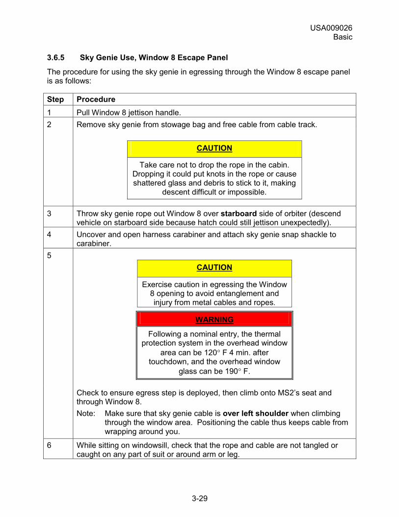
USA009026 Basic
3-29
3.6.5 Sky Genie Use, Window 8 Escape Panel
The procedure for using the sky genie in egressing through the Window 8 escape panel is as follows:
Step Procedure 1 Pull Window 8 jettison handle. 2 Remove sky genie from stowage bag and free cable from cable track.
CAUTION
Take care not to drop the rope in the cabin. Dropping it could put knots in the rope or cause shattered glass and debris to stick to it, making
descent difficult or impossible.
3 Throw sky genie rope out Window 8 over starboard side of orbiter (descend vehicle on starboard side because hatch could still jettison unexpectedly).
4 Uncover and open harness carabiner and attach sky genie snap shackle to carabiner.
5 CAUTION
Exercise caution in egressing the Window 8 opening to avoid entanglement and injury from metal cables and ropes.
WARNING
Following a nominal entry, the thermal protection system in the overhead window
area can be 120° F 4 min. after touchdown, and the overhead window
glass can be 190° F.
Check to ensure egress step is deployed, then climb onto MS2�s seat and through Window 8. Note: Make sure that sky genie cable is over left shoulder when climbing
through the window area. Positioning the cable thus keeps cable from wrapping around you.
6 While sitting on windowsill, check that the rope and cable are not tangled or caught on any part of suit or around arm or leg.
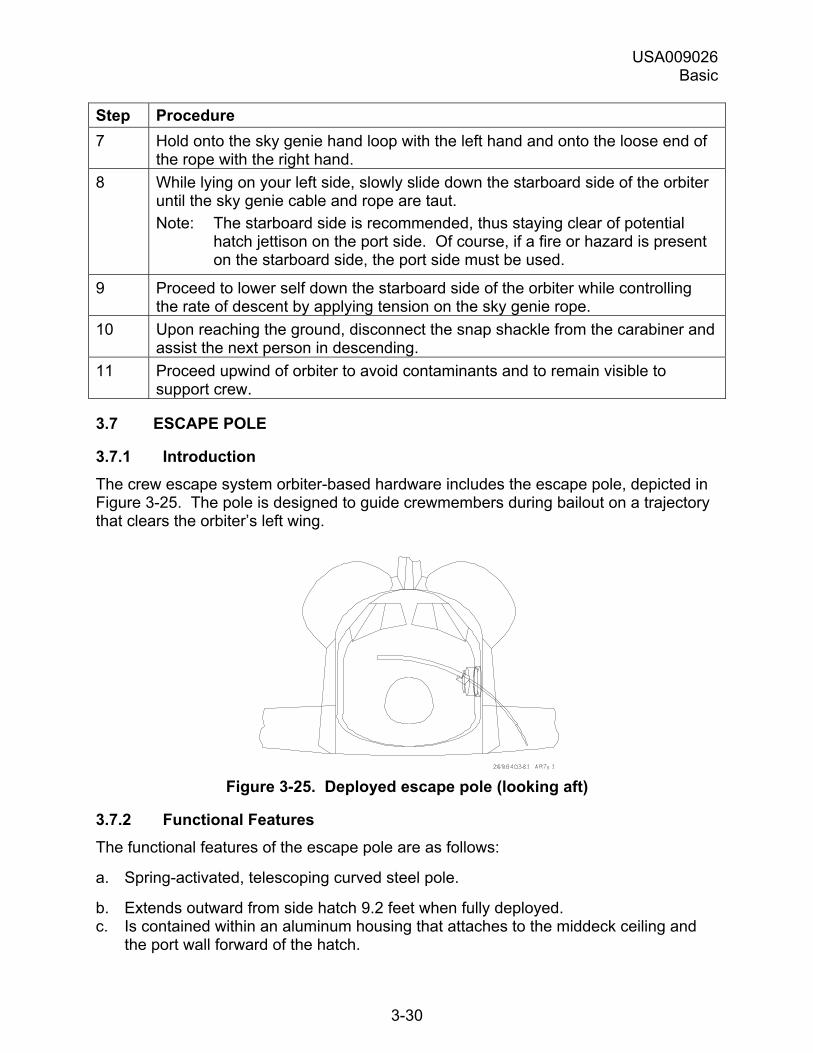
USA009026 Basic
3-30
Step Procedure 7 Hold onto the sky genie hand loop with the left hand and onto the loose end of
the rope with the right hand. 8 While lying on your left side, slowly slide down the starboard side of the orbiter
until the sky genie cable and rope are taut. Note: The starboard side is recommended, thus staying clear of potential
hatch jettison on the port side. Of course, if a fire or hazard is present on the starboard side, the port side must be used.
9 Proceed to lower self down the starboard side of the orbiter while controlling the rate of descent by applying tension on the sky genie rope.
10 Upon reaching the ground, disconnect the snap shackle from the carabiner and assist the next person in descending.
11 Proceed upwind of orbiter to avoid contaminants and to remain visible to support crew.
3.7 ESCAPE POLE
3.7.1 Introduction The crew escape system orbiter-based hardware includes the escape pole, depicted in Figure 3-25. The pole is designed to guide crewmembers during bailout on a trajectory that clears the orbiter�s left wing.
Figure 3-25. Deployed escape pole (looking aft)
3.7.2 Functional Features The functional features of the escape pole are as follows:
a. Spring-activated, telescoping curved steel pole.
b. Extends outward from side hatch 9.2 feet when fully deployed. c. Is contained within an aluminum housing that attaches to the middeck ceiling and
the port wall forward of the hatch.
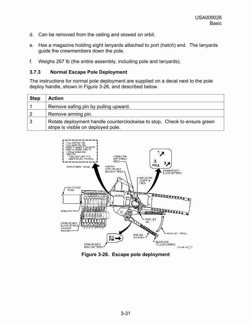
USA009026 Basic
3-31
d. Can be removed from the ceiling and stowed on orbit.
e. Has a magazine holding eight lanyards attached to port (hatch) end. The lanyards guide the crewmembers down the pole.
f. Weighs 267 lb (the entire assembly, including pole and lanyards).
3.7.3 Normal Escape Pole Deployment
The instructions for normal pole deployment are supplied on a decal next to the pole deploy handle, shown in Figure 3-26, and described below.
Step Action 1 Remove safing pin by pulling upward. 2 Remove arming pin. 3 Rotate deployment handle counterclockwise to stop. Check to ensure green
stripe is visible on deployed pole.
Figure 3-26. Escape pole deployment
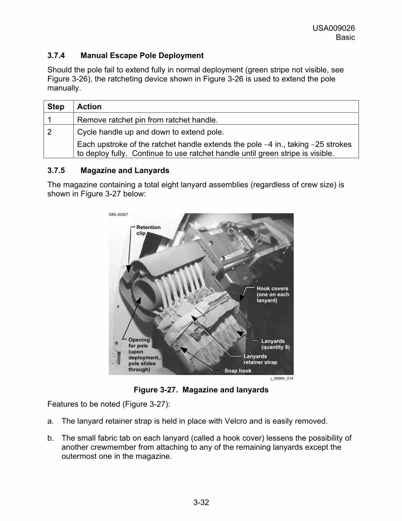
USA009026 Basic
3-32
3.7.4 Manual Escape Pole Deployment
Should the pole fail to extend fully in normal deployment (green stripe not visible, see Figure 3-26), the ratcheting device shown in Figure 3-26 is used to extend the pole manually.
Step Action 1 Remove ratchet pin from ratchet handle. 2 Cycle handle up and down to extend pole.
Each upstroke of the ratchet handle extends the pole ∼4 in., taking ∼25 strokes to deploy fully. Continue to use ratchet handle until green stripe is visible.
3.7.5 Magazine and Lanyards
The magazine containing a total eight lanyard assemblies (regardless of crew size) is shown in Figure 3-27 below:
S88-30067
Retentionclip
Openingfor pole(upondeployment,pole slidesthrough)
Hook covers(one on eachlanyard)
Lanyards(quantity 8)
Lanyardsretainer strap
Snap hookj_26984_014
Figure 3-27. Magazine and lanyards
Features to be noted (Figure 3-27):
a. The lanyard retainer strap is held in place with Velcro and is easily removed.
b. The small fabric tab on each lanyard (called a hook cover) lessens the possibility of another crewmember from attaching to any of the remaining lanyards except the outermost one in the magazine.
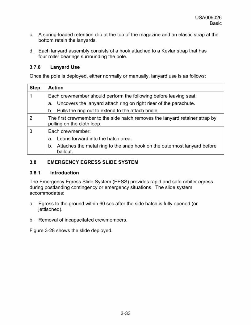
USA009026 Basic
3-33
c. A spring-loaded retention clip at the top of the magazine and an elastic strap at the bottom retain the lanyards.
d. Each lanyard assembly consists of a hook attached to a Kevlar strap that has four roller bearings surrounding the pole.
3.7.6 Lanyard Use
Once the pole is deployed, either normally or manually, lanyard use is as follows:
Step Action 1 Each crewmember should perform the following before leaving seat:
a. Uncovers the lanyard attach ring on right riser of the parachute. b. Pulls the ring out to extend to the attach bridle.
2 The first crewmember to the side hatch removes the lanyard retainer strap by pulling on the cloth loop.
3 Each crewmember: a. Leans forward into the hatch area. b. Attaches the metal ring to the snap hook on the outermost lanyard before
bailout.
3.8 EMERGENCY EGRESS SLIDE SYSTEM
3.8.1 Introduction
The Emergency Egress Slide System (EESS) provides rapid and safe orbiter egress during postlanding contingency or emergency situations. The slide system accommodates:
a. Egress to the ground within 60 sec after the side hatch is fully opened (or jettisoned).
b. Removal of incapacitated crewmembers.
Figure 3-28 shows the slide deployed.
USA009026 Basic
3-34
Figure 3-28. Emergency egress slide deployed
(side hatch opened normally)
3.8.2 Physical Characteristics
The slide system consists of the following components:
3.8.2.1 Inflatable Slide
Constructed of neoprene-coated nylon fabric with a sliding surface of urethane-coated nylon fabric.
Inflated by an argon bottle (see next item) to ~2.75 psig. A vent valve, with adjustment screw, bleeds off pressures greater than 3.0 psig.
Remains functional for at least 6 min after inflation.
3.8.2.2 Pressurized Argon Bottle
Pressurized to 3000 psig; equipped with pressure gauge.
When actuated by pulling the inflation lanyard, argon flows at 400 psi through a hose to an aspirator. The aspirator pulls in ambient air (approximately four times the volume of the argon) to inflate the slide with an air and argon mixture in ~3 sec.
USA009026 Basic
3-35
3.8.2.3 Slide Support Assembly
Consists of two aluminum plates and brackets attached to wall below side hatch.
Inflatable part of the slide is attached to the support assembly by fabric that is attached to the support assembly. The inflatable portion can be detached from the support by pulling on detach lanyard.
Support assembly (with slide attached) is easily removed and attached to hatch.
3.8.2.4 Slide Container
Made of aluminum; equipped with handle for easy removal.
Attached to orbiter floor and port wall below side hatch by four pins.
Equipped with window for viewing argon bottle pressure gauge.
3.8.2.5 Chem Lights
Two high intensity lightsticks are located above the side hatch.
3.8.2.6 Reingress Strap
The crew module can be reingressed by climbing up the slide using the reingress strap, Velcroed on the aft side of the slide.
3.8.3 Slide Deployment
The egress slide can be deployed in two ways:
a. With the hatch opened normally.
b. With the hatch jettisoned.
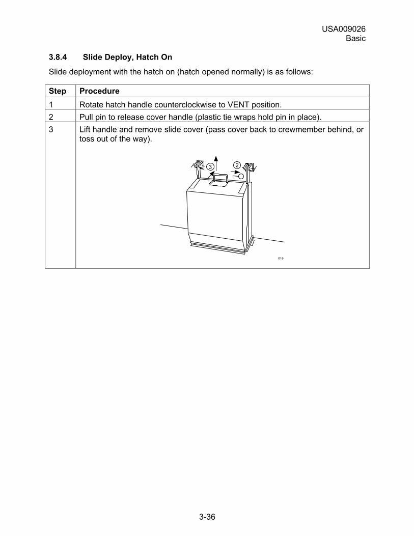
USA009026 Basic
3-36
3.8.4 Slide Deploy, Hatch On
Slide deployment with the hatch on (hatch opened normally) is as follows:
Step Procedure 1 Rotate hatch handle counterclockwise to VENT position. 2 Pull pin to release cover handle (plastic tie wraps hold pin in place). 3 Lift handle and remove slide cover (pass cover back to crewmember behind, or
toss out of the way).
016
23
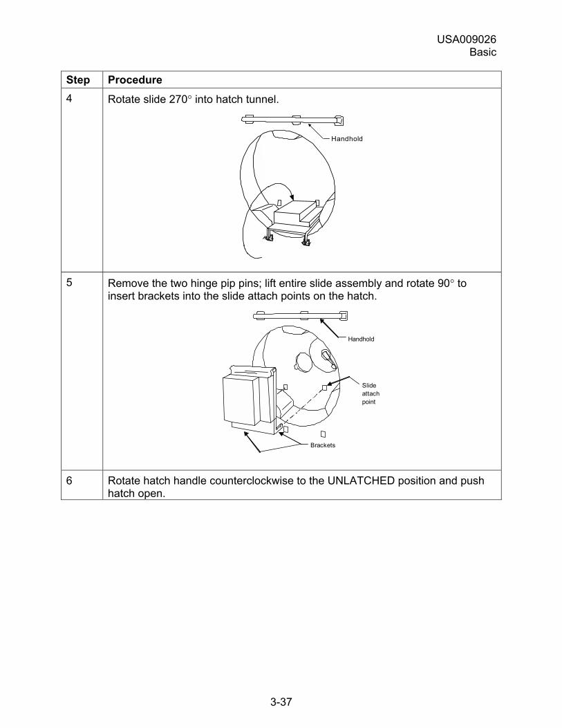
USA009026 Basic
3-37
Step Procedure 4 Rotate slide 270° into hatch tunnel.
H a n d h o l d
5 Remove the two hinge pip pins; lift entire slide assembly and rotate 90° to
insert brackets into the slide attach points on the hatch.
Brackets
Handhold
Slide attachpoint
6 Rotate hatch handle counterclockwise to the UNLATCHED position and push
hatch open.
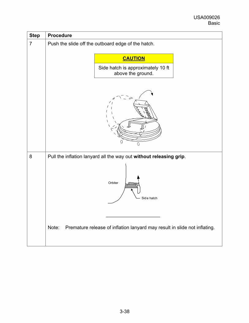
USA009026 Basic
3-38
Step Procedure 7 Push the slide off the outboard edge of the hatch.
CAUTION
Side hatch is approximately 10 ft above the ground.
8 Pull the inflation lanyard all the way out without releasing grip.
Orbiter
Sid e hatch
Note: Premature release of inflation lanyard may result in slide not inflating.
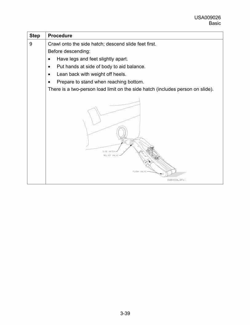
USA009026 Basic
3-39
Step Procedure 9 Crawl onto the side hatch; descend slide feet first.
Before descending: • Have legs and feet slightly apart. • Put hands at side of body to aid balance. • Lean back with weight off heels. • Prepare to stand when reaching bottom. There is a two-person load limit on the side hatch (includes person on slide).
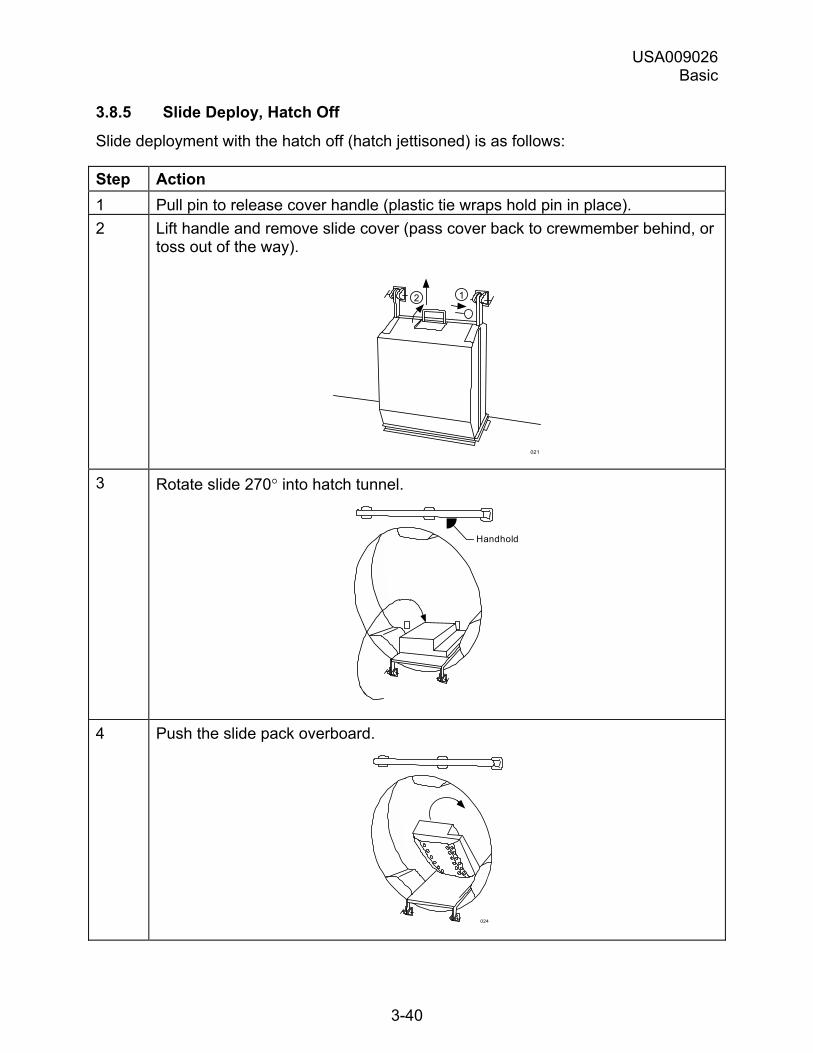
USA009026 Basic
3-40
3.8.5 Slide Deploy, Hatch Off
Slide deployment with the hatch off (hatch jettisoned) is as follows:
Step Action 1 Pull pin to release cover handle (plastic tie wraps hold pin in place). 2 Lift handle and remove slide cover (pass cover back to crewmember behind, or
toss out of the way).
021
12
3 Rotate slide 270° into hatch tunnel.
H a n d h o l d
4 Push the slide pack overboard.
024
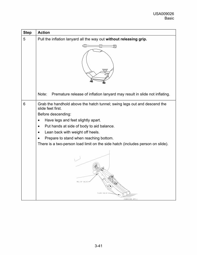
USA009026 Basic
3-41
Step Action 5 Pull the inflation lanyard all the way out without releasing grip.
Note: Premature release of inflation lanyard may result in slide not inflating.
6 Grab the handhold above the hatch tunnel; swing legs out and descend the slide feet first. Before descending: • Have legs and feet slightly apart. • Put hands at side of body to aid balance. • Lean back with weight off heels. • Prepare to stand when reaching bottom. There is a two-person load limit on the side hatch (includes person on slide).
USA009026 Basic
4-1
4.0 NOMINAL CREW SEAT PROCEDURES
4.1 OVERVIEW
4.1.1 Introduction
There are numerous procedures that must be completed during nominal seat ingress/egress. Seat ingress/egress will occur during:
a. Prelaunch
b. Postinsertion
c. Deorbit Prep
d. Postlanding
4.1.2 Purpose
This chapter describes steps and procedures required for nominal seat ingress/egress.
4.1.3 Objectives
After completing this chapter, you will be able to identify:
a. Steps for prelaunch seat ingress.
b. Steps for postinsertion seat egress.
c. Steps for deorbit prep seat ingress.
d. Steps for postlanding seat egress.
In This Chapter
Section describes seat ingress/egress as follows:
Section Page Nominal Seat Ingress/Egress 4-1
4.2 NOMINAL SEAT INGRESS/EGRESS
Nominal seat ingress and egress procedures are defined by the mission phase during which the ingress or the egress occurs.
Ingress and egress during each mission phase are discussed below. For seat/orbiter egress because of a mission scrub, see �Nominal seat/orbiter egress� at the end of the section.
USA009026 Basic
4-2
4.2.1 Prelaunch Seat Ingress
The sequence of events is as follows immediately before and during prelaunch ingress (T � 3:45:00 to T � 1:30:00):
Pre-ingress:
Time Step Action ~ T - 3:45 1 Don flight suits and conducting pressure checks in
the Operations and Checkout (O&C) building suit room.
~ T - 3:15 2 Crew Transport to 195-foot level of the Fixed Service Structure (FSS).
~ T - 2:45 3 In the white room on the Orbiter Access Arm (OAA), the Closeout Crew and the suit technician assist the crew in donning a parachute harness and a CCA (comm cap).
Ingress:
Time Step Action ~ T - 2:25
1 Crewmembers ingress through the orbiter side hatch into the flight deck and middeck to assigned seats in the following order (ingress into the two areas can be at the same time):
Flight Deck CDR (Seat 1) PLT (Seat 2) MS1 (Seat 3) MS2 (Seat 4)
Middeck MS5/PS2 (Seat 7)
MS3 (Seat 5) MS4/PS1 (Seat 6)
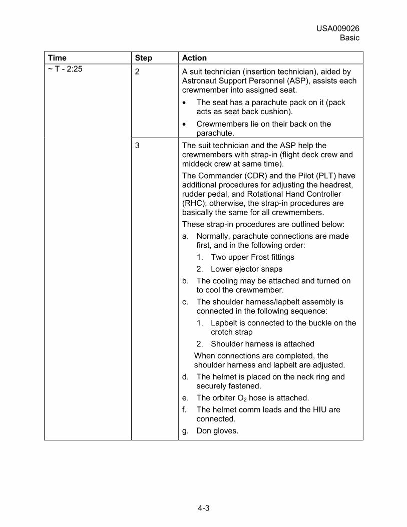
USA009026 Basic
4-3
Time Step Action ~ T - 2:25 2 A suit technician (insertion technician), aided by
Astronaut Support Personnel (ASP), assists each crewmember into assigned seat. • The seat has a parachute pack on it (pack
acts as seat back cushion). • Crewmembers lie on their back on the
parachute. 3 The suit technician and the ASP help the
crewmembers with strap-in (flight deck crew and middeck crew at same time). The Commander (CDR) and the Pilot (PLT) have additional procedures for adjusting the headrest, rudder pedal, and Rotational Hand Controller (RHC); otherwise, the strap-in procedures are basically the same for all crewmembers. These strap-in procedures are outlined below: a. Normally, parachute connections are made
first, and in the following order: 1. Two upper Frost fittings 2. Lower ejector snaps
b. The cooling may be attached and turned on to cool the crewmember.
c. The shoulder harness/lapbelt assembly is connected in the following sequence: 1. Lapbelt is connected to the buckle on the
crotch strap 2. Shoulder harness is attached
When connections are completed, the shoulder harness and lapbelt are adjusted.
d. The helmet is placed on the neck ring and securely fastened.
e. The orbiter O2 hose is attached. f. The helmet comm leads and the HIU are
connected. g. Don gloves.
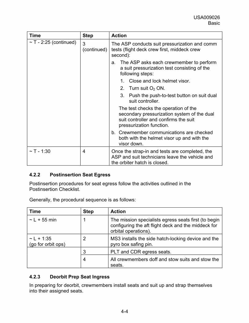
USA009026 Basic
4-4
Time Step Action ~ T - 2:25 (continued) 3
(continued)The ASP conducts suit pressurization and comm tests (flight deck crew first, middeck crew second): a. The ASP asks each crewmember to perform
a suit pressurization test consisting of the following steps: 1. Close and lock helmet visor. 2. Turn suit O2 ON. 3. Push the push-to-test button on suit dual
suit controller. The test checks the operation of the secondary pressurization system of the dual suit controller and confirms the suit pressurization function.
b. Crewmember communications are checked both with the helmet visor up and with the visor down.
~ T - 1:30 4 Once the strap-in and tests are completed, the ASP and suit technicians leave the vehicle and the orbiter hatch is closed.
4.2.2 Postinsertion Seat Egress
Postinsertion procedures for seat egress follow the activities outlined in the Postinsertion Checklist.
Generally, the procedural sequence is as follows:
Time Step Action ~ L + 55 min 1 The mission specialists egress seats first (to begin
configuring the aft flight deck and the middeck for orbital operations).
~ L + 1:35 (go for orbit ops)
2 MS3 installs the side hatch-locking device and the pyro box safing pin.
3 PLT and CDR egress seats. 4 All crewmembers doff and stow suits and stow the
seats.
4.2.3 Deorbit Prep Seat Ingress In preparing for deorbit, crewmembers install seats and suit up and strap themselves into their assigned seats.
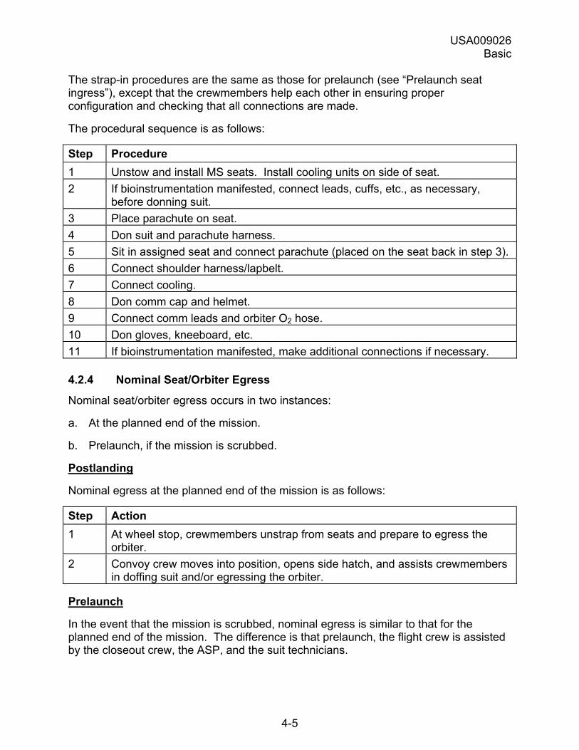
USA009026 Basic
4-5
The strap-in procedures are the same as those for prelaunch (see �Prelaunch seat ingress�), except that the crewmembers help each other in ensuring proper configuration and checking that all connections are made.
The procedural sequence is as follows:
Step Procedure 1 Unstow and install MS seats. Install cooling units on side of seat. 2 If bioinstrumentation manifested, connect leads, cuffs, etc., as necessary,
before donning suit. 3 Place parachute on seat. 4 Don suit and parachute harness. 5 Sit in assigned seat and connect parachute (placed on the seat back in step 3). 6 Connect shoulder harness/lapbelt. 7 Connect cooling. 8 Don comm cap and helmet. 9 Connect comm leads and orbiter O2 hose. 10 Don gloves, kneeboard, etc. 11 If bioinstrumentation manifested, make additional connections if necessary.
4.2.4 Nominal Seat/Orbiter Egress
Nominal seat/orbiter egress occurs in two instances:
a. At the planned end of the mission.
b. Prelaunch, if the mission is scrubbed.
Postlanding
Nominal egress at the planned end of the mission is as follows:
Step Action 1 At wheel stop, crewmembers unstrap from seats and prepare to egress the
orbiter. 2 Convoy crew moves into position, opens side hatch, and assists crewmembers
in doffing suit and/or egressing the orbiter.
Prelaunch
In the event that the mission is scrubbed, nominal egress is similar to that for the planned end of the mission. The difference is that prelaunch, the flight crew is assisted by the closeout crew, the ASP, and the suit technicians.
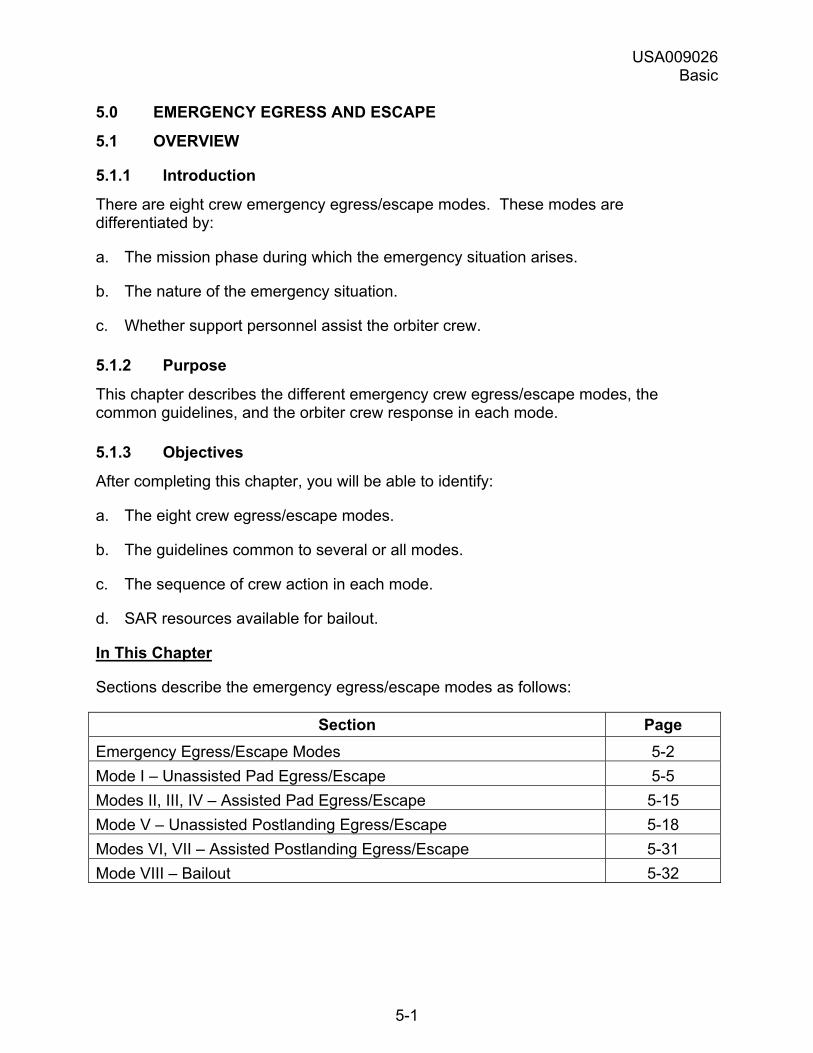
USA009026 Basic
5-1
5.0 EMERGENCY EGRESS AND ESCAPE
5.1 OVERVIEW
5.1.1 Introduction
There are eight crew emergency egress/escape modes. These modes are differentiated by:
a. The mission phase during which the emergency situation arises.
b. The nature of the emergency situation.
c. Whether support personnel assist the orbiter crew.
5.1.2 Purpose
This chapter describes the different emergency crew egress/escape modes, the common guidelines, and the orbiter crew response in each mode.
5.1.3 Objectives
After completing this chapter, you will be able to identify:
a. The eight crew egress/escape modes.
b. The guidelines common to several or all modes.
c. The sequence of crew action in each mode.
d. SAR resources available for bailout.
In This Chapter
Sections describe the emergency egress/escape modes as follows:
Section Page Emergency Egress/Escape Modes 5-2 Mode I � Unassisted Pad Egress/Escape 5-5 Modes II, III, IV � Assisted Pad Egress/Escape 5-15 Mode V � Unassisted Postlanding Egress/Escape 5-18 Modes VI, VII � Assisted Postlanding Egress/Escape 5-31 Mode VIII � Bailout 5-32
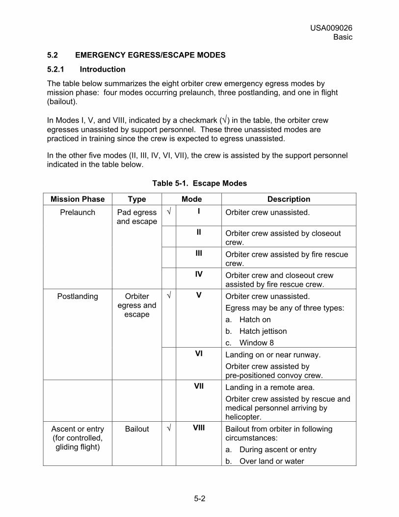
USA009026 Basic
5-2
5.2 EMERGENCY EGRESS/ESCAPE MODES
5.2.1 Introduction
The table below summarizes the eight orbiter crew emergency egress modes by mission phase: four modes occurring prelaunch, three postlanding, and one in flight (bailout).
In Modes I, V, and VIII, indicated by a checkmark (√) in the table, the orbiter crew egresses unassisted by support personnel. These three unassisted modes are practiced in training since the crew is expected to egress unassisted.
In the other five modes (II, III, IV, VI, VII), the crew is assisted by the support personnel indicated in the table below.
Table 5-1. Escape Modes
Mission Phase Type Mode Description Prelaunch Pad egress
and escape √ I Orbiter crew unassisted.
II Orbiter crew assisted by closeout crew.
III Orbiter crew assisted by fire rescue crew.
IV Orbiter crew and closeout crew assisted by fire rescue crew.
Postlanding Orbiter egress and
escape
√ V Orbiter crew unassisted. Egress may be any of three types: a. Hatch on b. Hatch jettison c. Window 8
VI Landing on or near runway. Orbiter crew assisted by pre-positioned convoy crew.
VII Landing in a remote area. Orbiter crew assisted by rescue and medical personnel arriving by helicopter.
Ascent or entry (for controlled, gliding flight)
Bailout √ VIII Bailout from orbiter in following circumstances: a. During ascent or entry b. Over land or water
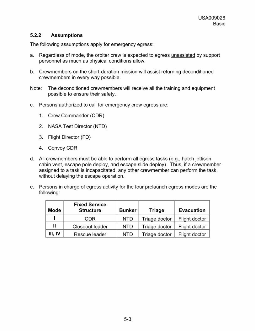
USA009026 Basic
5-3
5.2.2 Assumptions
The following assumptions apply for emergency egress:
a. Regardless of mode, the orbiter crew is expected to egress unassisted by support personnel as much as physical conditions allow.
b. Crewmembers on the short-duration mission will assist returning deconditioned crewmembers in every way possible.
Note: The deconditioned crewmembers will receive all the training and equipment possible to ensure their safety.
c. Persons authorized to call for emergency crew egress are:
1. Crew Commander (CDR)
2. NASA Test Director (NTD)
3. Flight Director (FD)
4. Convoy CDR
d. All crewmembers must be able to perform all egress tasks (e.g., hatch jettison, cabin vent, escape pole deploy, and escape slide deploy). Thus, if a crewmember assigned to a task is incapacitated, any other crewmember can perform the task without delaying the escape operation.
e. Persons in charge of egress activity for the four prelaunch egress modes are the following:
Mode Fixed Service
Structure Bunker Triage Evacuation I CDR NTD Triage doctor Flight doctor II Closeout leader NTD Triage doctor Flight doctor
III, IV Rescue leader NTD Triage doctor Flight doctor
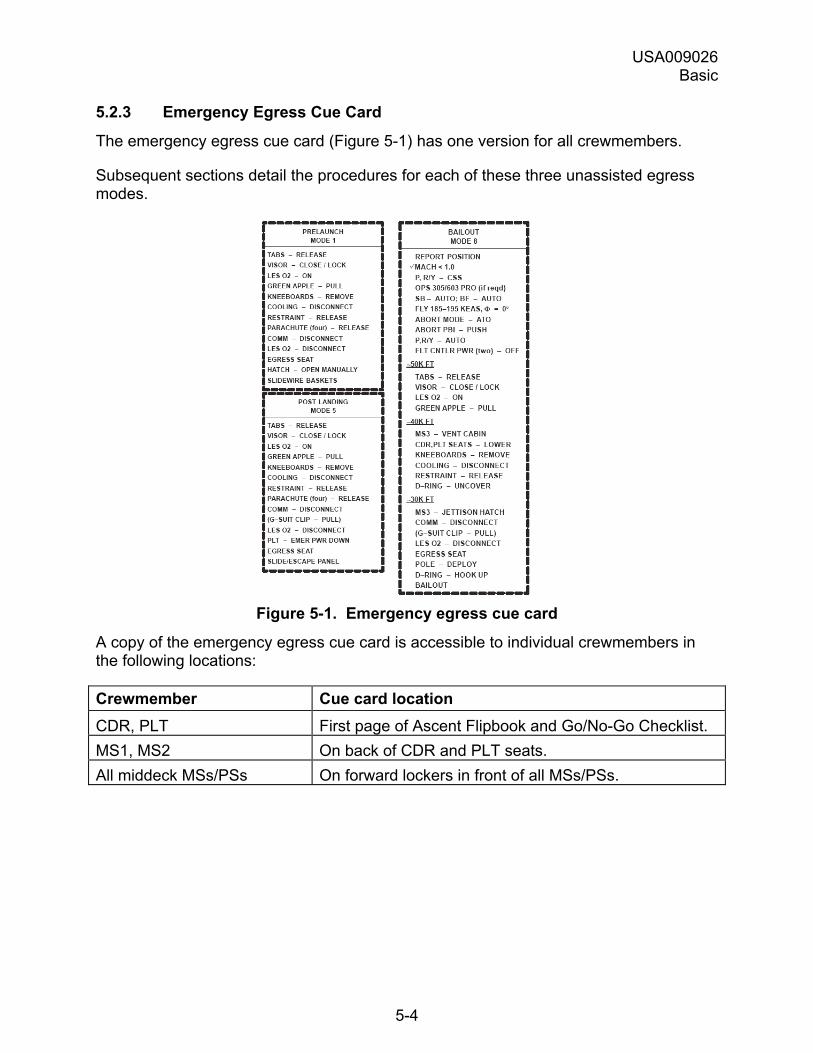
USA009026 Basic
5-4
5.2.3 Emergency Egress Cue Card
The emergency egress cue card (Figure 5-1) has one version for all crewmembers.
Subsequent sections detail the procedures for each of these three unassisted egress modes.
Figure 5-1. Emergency egress cue card
A copy of the emergency egress cue card is accessible to individual crewmembers in the following locations:
Crewmember Cue card location CDR, PLT First page of Ascent Flipbook and Go/No-Go Checklist. MS1, MS2 On back of CDR and PLT seats. All middeck MSs/PSs On forward lockers in front of all MSs/PSs.
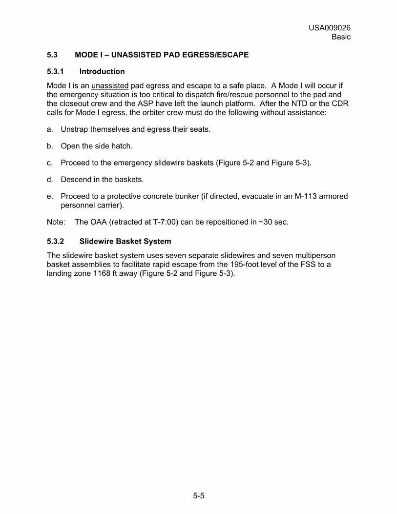
USA009026 Basic
5-5
5.3 MODE I � UNASSISTED PAD EGRESS/ESCAPE
5.3.1 Introduction
Mode I is an unassisted pad egress and escape to a safe place. A Mode I will occur if the emergency situation is too critical to dispatch fire/rescue personnel to the pad and the closeout crew and the ASP have left the launch platform. After the NTD or the CDR calls for Mode I egress, the orbiter crew must do the following without assistance:
a. Unstrap themselves and egress their seats.
b. Open the side hatch.
c. Proceed to the emergency slidewire baskets (Figure 5-2 and Figure 5-3).
d. Descend in the baskets.
e. Proceed to a protective concrete bunker (if directed, evacuate in an M-113 armored personnel carrier).
Note: The OAA (retracted at T-7:00) can be repositioned in ~30 sec.
5.3.2 Slidewire Basket System
The slidewire basket system uses seven separate slidewires and seven multiperson basket assemblies to facilitate rapid escape from the 195-foot level of the FSS to a landing zone 1168 ft away (Figure 5-2 and Figure 5-3).
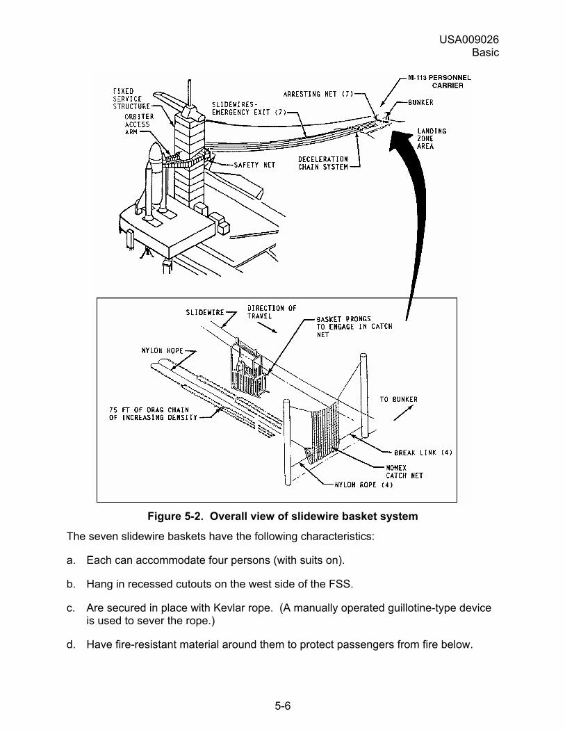
USA009026 Basic
5-6
Figure 5-2. Overall view of slidewire basket system
The seven slidewire baskets have the following characteristics:
a. Each can accommodate four persons (with suits on).
b. Hang in recessed cutouts on the west side of the FSS.
c. Are secured in place with Kevlar rope. (A manually operated guillotine-type device is used to sever the rope.)
d. Have fire-resistant material around them to protect passengers from fire below.
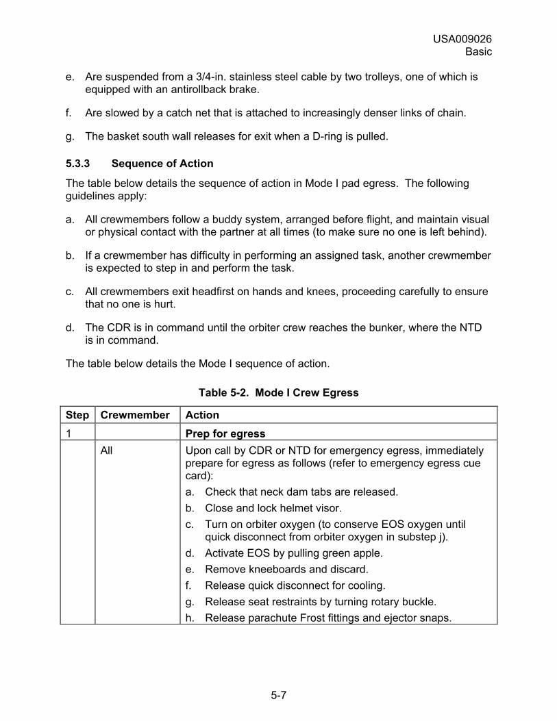
USA009026 Basic
5-7
e. Are suspended from a 3/4-in. stainless steel cable by two trolleys, one of which is equipped with an antirollback brake.
f. Are slowed by a catch net that is attached to increasingly denser links of chain.
g. The basket south wall releases for exit when a D-ring is pulled.
5.3.3 Sequence of Action
The table below details the sequence of action in Mode I pad egress. The following guidelines apply:
a. All crewmembers follow a buddy system, arranged before flight, and maintain visual or physical contact with the partner at all times (to make sure no one is left behind).
b. If a crewmember has difficulty in performing an assigned task, another crewmember is expected to step in and perform the task.
c. All crewmembers exit headfirst on hands and knees, proceeding carefully to ensure that no one is hurt.
d. The CDR is in command until the orbiter crew reaches the bunker, where the NTD is in command.
The table below details the Mode I sequence of action.
Table 5-2. Mode I Crew Egress
Step Crewmember Action 1 Prep for egress All Upon call by CDR or NTD for emergency egress, immediately
prepare for egress as follows (refer to emergency egress cue card): a. Check that neck dam tabs are released. b. Close and lock helmet visor. c. Turn on orbiter oxygen (to conserve EOS oxygen until
quick disconnect from orbiter oxygen in substep j). d. Activate EOS by pulling green apple. e. Remove kneeboards and discard. f. Release quick disconnect for cooling. g. Release seat restraints by turning rotary buckle. h. Release parachute Frost fittings and ejector snaps.
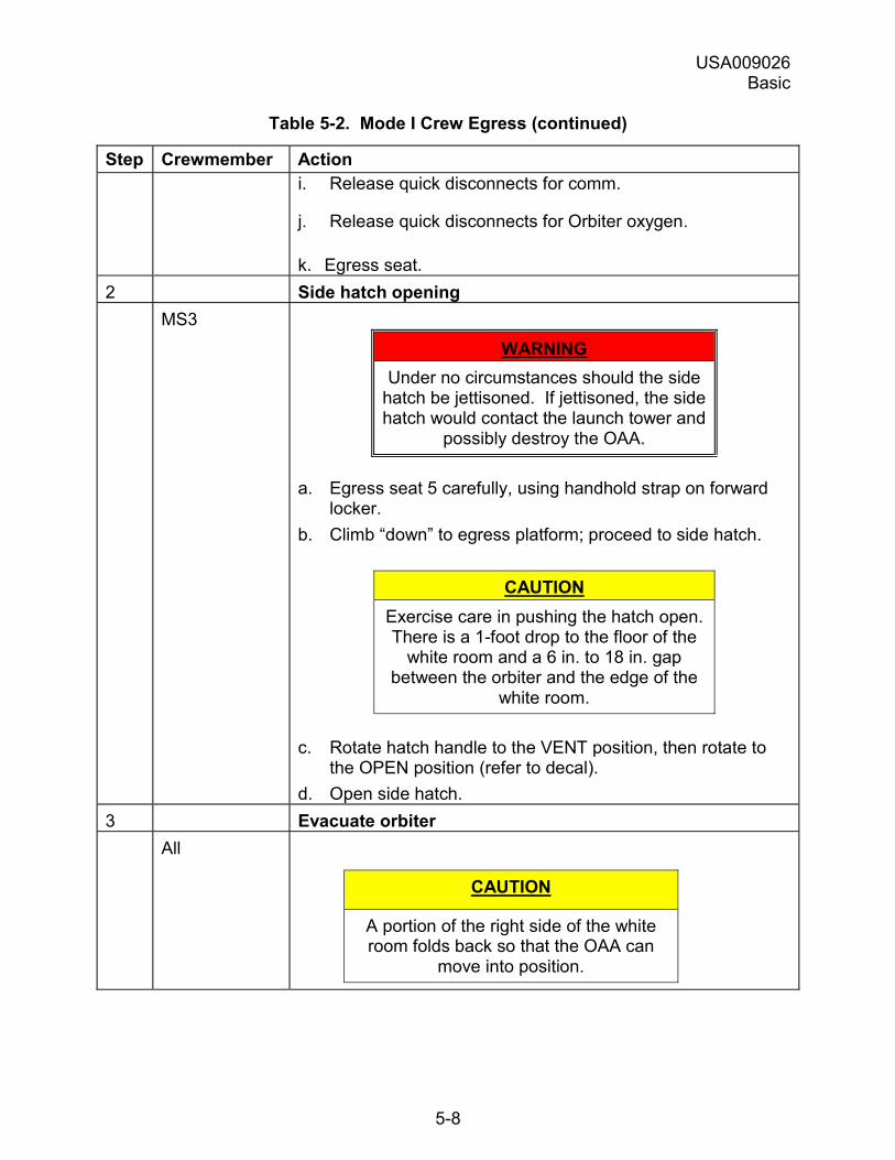
USA009026 Basic
5-8
Table 5-2. Mode I Crew Egress (continued)
Step Crewmember Action i. Release quick disconnects for comm.
j. Release quick disconnects for Orbiter oxygen.
k. Egress seat. 2 Side hatch opening MS3
WARNING Under no circumstances should the side
hatch be jettisoned. If jettisoned, the side hatch would contact the launch tower and
possibly destroy the OAA.
a. Egress seat 5 carefully, using handhold strap on forward locker.
b. Climb �down� to egress platform; proceed to side hatch.
CAUTION Exercise care in pushing the hatch open. There is a 1-foot drop to the floor of the
white room and a 6 in. to 18 in. gap between the orbiter and the edge of the
white room.
c. Rotate hatch handle to the VENT position, then rotate to the OPEN position (refer to decal).
d. Open side hatch. 3 Evacuate orbiter All
CAUTION
A portion of the right side of the white room folds back so that the OAA can
move into position.

USA009026 Basic
5-9
Table 5-2. Mode I Crew Egress (continued)
Step Crewmember Action This creates an unprotected area on that side:
You can fall from this unprotected area if you veer too far right.
All Crawl out side hatch headfirst. 4 Proceed to baskets All Follow marked route (shown below) through the white room
and across the OAA and the FSS to the baskets (which are located in recesses on the west side of the FSS). The primary and alternate routes are as shown below:
Figure 5-3. Primary and alternate routes to baskets
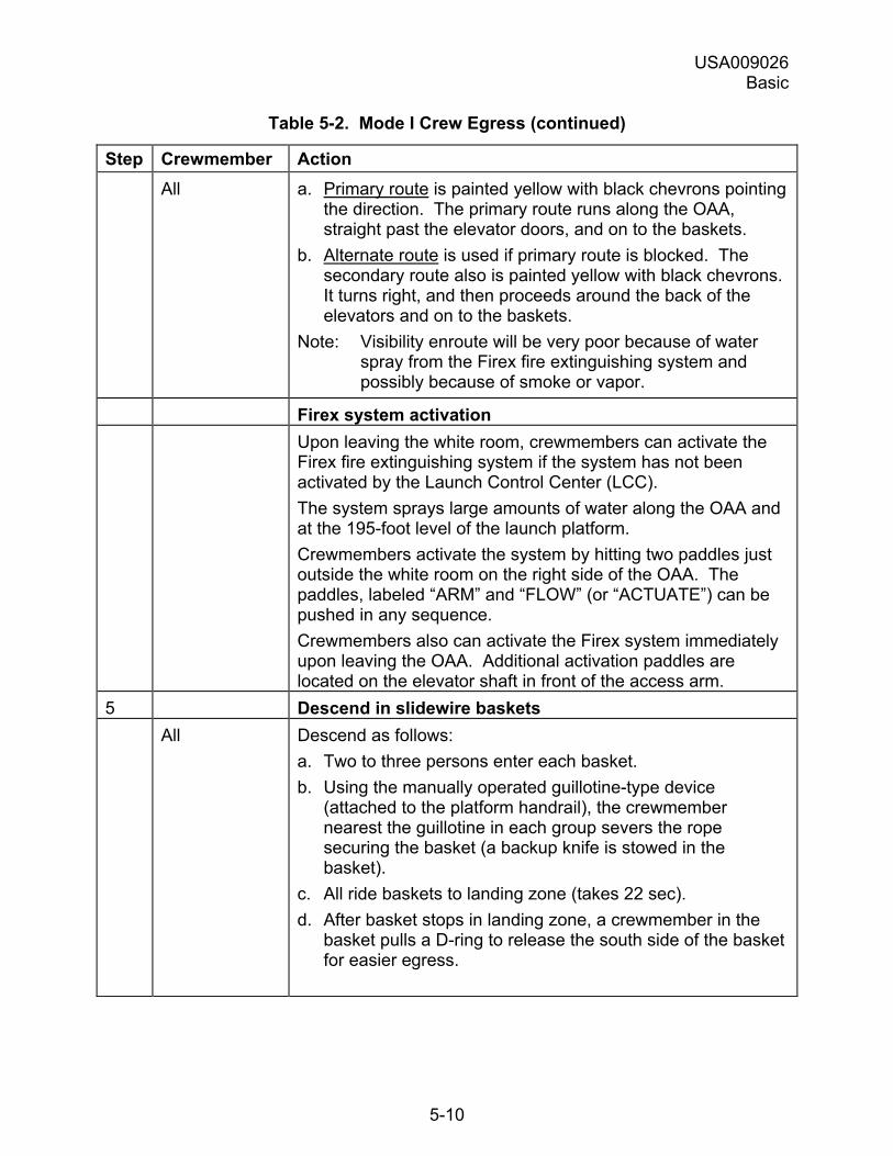
USA009026 Basic
5-10
Table 5-2. Mode I Crew Egress (continued)
Step Crewmember Action All a. Primary route is painted yellow with black chevrons pointing
the direction. The primary route runs along the OAA, straight past the elevator doors, and on to the baskets.
b. Alternate route is used if primary route is blocked. The secondary route also is painted yellow with black chevrons. It turns right, and then proceeds around the back of the elevators and on to the baskets.
Note: Visibility enroute will be very poor because of water spray from the Firex fire extinguishing system and possibly because of smoke or vapor.
Firex system activation Upon leaving the white room, crewmembers can activate the
Firex fire extinguishing system if the system has not been activated by the Launch Control Center (LCC). The system sprays large amounts of water along the OAA and at the 195-foot level of the launch platform. Crewmembers activate the system by hitting two paddles just outside the white room on the right side of the OAA. The paddles, labeled �ARM� and �FLOW� (or �ACTUATE�) can be pushed in any sequence. Crewmembers also can activate the Firex system immediately upon leaving the OAA. Additional activation paddles are located on the elevator shaft in front of the access arm.
5 Descend in slidewire baskets All Descend as follows:
a. Two to three persons enter each basket. b. Using the manually operated guillotine-type device
(attached to the platform handrail), the crewmember nearest the guillotine in each group severs the rope securing the basket (a backup knife is stowed in the basket).
c. All ride baskets to landing zone (takes 22 sec). d. After basket stops in landing zone, a crewmember in the
basket pulls a D-ring to release the south side of the basket for easier egress.
USA009026 Basic
5-11
Table 5-2. Mode I Crew Egress (concluded)
Step Crewmember Action All
CAUTION The baskets tend to rise as each
crewmember exits. Exercise care in jumping out.
CAUTION
To avoid being hit by descending baskets, stay on the cement walkways
enroute to the bunker.
e. Exit basket and go directly to the bunker being sure to stay on cement walkways.
6 In bunker All Follow NTD�s directions whether to:
a. Stay in bunker until rescuers arrive. The bunker has breathing air, water, phone line communications, and medical supplies.
b. Evacuate in M-113 armored personnel carrier (Figure 5.4) to a designated helicopter landing site.
5.3.4 Armored Personnel Carrier
The M-113 armored personnel carrier used to evacuate the orbiter crew and fire rescue personnel from the pad area (Figure 5-4).
The M-113 is located at the bunker and driven to helipad sites considered safe for helicopters to land.
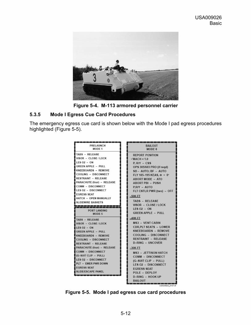
USA009026 Basic
5-12
Figure 5-4. M-113 armored personnel carrier
5.3.5 Mode I Egress Cue Card Procedures
The emergency egress cue card is shown below with the Mode I pad egress procedures highlighted (Figure 5-5).
Figure 5-5. Mode I pad egress cue card procedures
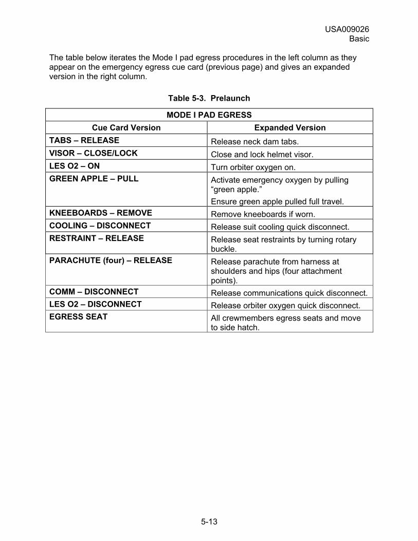
USA009026 Basic
5-13
The table below iterates the Mode I pad egress procedures in the left column as they appear on the emergency egress cue card (previous page) and gives an expanded version in the right column.
Table 5-3. Prelaunch
MODE I PAD EGRESS Cue Card Version Expanded Version
TABS � RELEASE Release neck dam tabs. VISOR � CLOSE/LOCK Close and lock helmet visor. LES O2 � ON Turn orbiter oxygen on. GREEN APPLE � PULL Activate emergency oxygen by pulling
�green apple.� Ensure green apple pulled full travel.
KNEEBOARDS � REMOVE Remove kneeboards if worn. COOLING � DISCONNECT Release suit cooling quick disconnect. RESTRAINT � RELEASE Release seat restraints by turning rotary
buckle. PARACHUTE (four) � RELEASE Release parachute from harness at
shoulders and hips (four attachment points).
COMM � DISCONNECT Release communications quick disconnect. LES O2 � DISCONNECT Release orbiter oxygen quick disconnect. EGRESS SEAT All crewmembers egress seats and move
to side hatch.
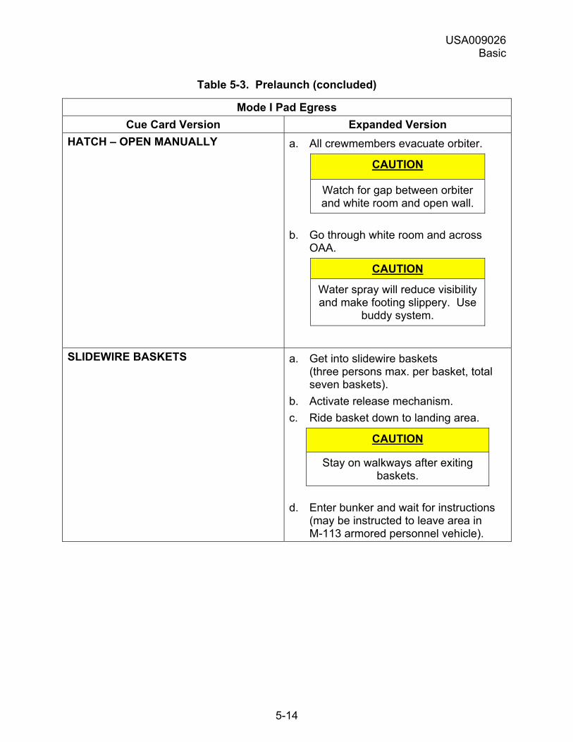
USA009026 Basic
5-14
Table 5-3. Prelaunch (concluded)
Mode I Pad Egress Cue Card Version Expanded Version
HATCH � OPEN MANUALLY a. All crewmembers evacuate orbiter.
CAUTION
Watch for gap between orbiter and white room and open wall.
b. Go through white room and across OAA.
CAUTION
Water spray will reduce visibility and make footing slippery. Use
buddy system.
SLIDEWIRE BASKETS a. Get into slidewire baskets (three persons max. per basket, total seven baskets).
b. Activate release mechanism. c. Ride basket down to landing area.
CAUTION
Stay on walkways after exiting baskets.
d. Enter bunker and wait for instructions (may be instructed to leave area in M-113 armored personnel vehicle).
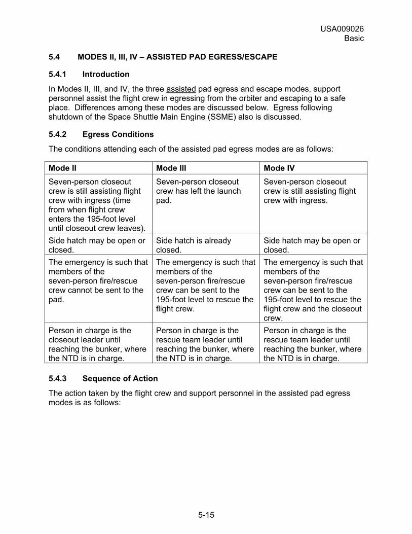
USA009026 Basic
5-15
5.4 MODES II, III, IV � ASSISTED PAD EGRESS/ESCAPE
5.4.1 Introduction
In Modes II, III, and IV, the three assisted pad egress and escape modes, support personnel assist the flight crew in egressing from the orbiter and escaping to a safe place. Differences among these modes are discussed below. Egress following shutdown of the Space Shuttle Main Engine (SSME) also is discussed.
5.4.2 Egress Conditions
The conditions attending each of the assisted pad egress modes are as follows:
Mode II Mode III Mode IV Seven-person closeout crew is still assisting flight crew with ingress (time from when flight crew enters the 195-foot level until closeout crew leaves).
Seven-person closeout crew has left the launch pad.
Seven-person closeout crew is still assisting flight crew with ingress.
Side hatch may be open or closed.
Side hatch is already closed.
Side hatch may be open or closed.
The emergency is such that members of the seven-person fire/rescue crew cannot be sent to the pad.
The emergency is such that members of the seven-person fire/rescue crew can be sent to the 195-foot level to rescue the flight crew.
The emergency is such that members of the seven-person fire/rescue crew can be sent to the 195-foot level to rescue the flight crew and the closeout crew.
Person in charge is the closeout leader until reaching the bunker, where the NTD is in charge.
Person in charge is the rescue team leader until reaching the bunker, where the NTD is in charge.
Person in charge is the rescue team leader until reaching the bunker, where the NTD is in charge.
5.4.3 Sequence of Action
The action taken by the flight crew and support personnel in the assisted pad egress modes is as follows:
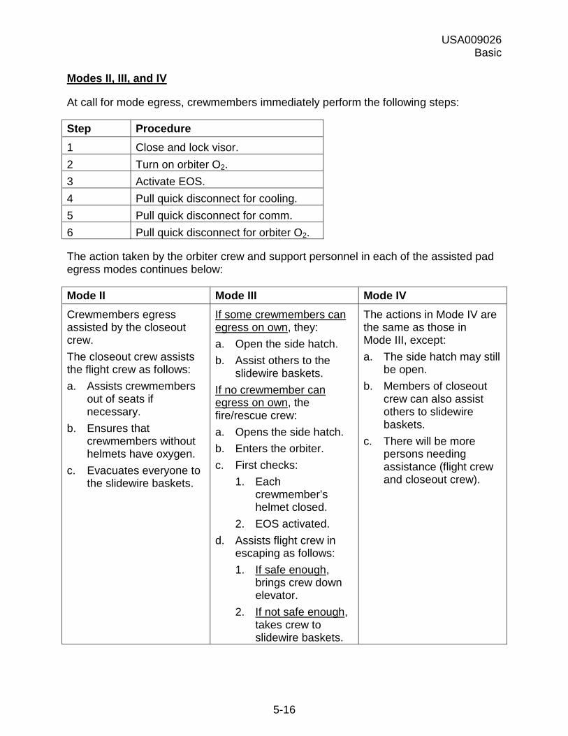
USA009026 Basic
5-16
Modes II, III, and IV
At call for mode egress, crewmembers immediately perform the following steps:
Step Procedure 1 Close and lock visor. 2 Turn on orbiter O2. 3 Activate EOS. 4 Pull quick disconnect for cooling. 5 Pull quick disconnect for comm. 6 Pull quick disconnect for orbiter O2. The action taken by the orbiter crew and support personnel in each of the assisted pad egress modes continues below:
Mode II Mode III Mode IV Crewmembers egress assisted by the closeout crew. The closeout crew assists the flight crew as follows: a. Assists crewmembers
out of seats if necessary.
b. Ensures that crewmembers without helmets have oxygen.
c. Evacuates everyone to the slidewire baskets.
If some crewmembers can egress on own, they: a. Open the side hatch. b. Assist others to the
slidewire baskets. If no crewmember can egress on own, the fire/rescue crew: a. Opens the side hatch. b. Enters the orbiter. c. First checks:
1. Each crewmember’s helmet closed.
2. EOS activated. d. Assists flight crew in
escaping as follows: 1. If safe enough,
brings crew down elevator.
2. If not safe enough, takes crew to slidewire baskets.
The actions in Mode IV are the same as those in Mode III, except: a. The side hatch may still
be open. b. Members of closeout
crew can also assist others to slidewire baskets.
c. There will be more persons needing assistance (flight crew and closeout crew).
USA009026 Basic
5-17
The rest of the action taken is the same as that for Mode I:
a. Descend in baskets.
b. Go to bunker.
c. Follow NTD�s direction whether to stay or evacuate in M-113.
5.4.4 SSME Shutdown
Following a shutdown of the SSME, the NTD receives information from LCC console operators about the status of the system and whether the system has shut down safely.
Once it is determined that the system has shut down safely, the orbiter crew is told that there is a launch scrub and to begin safing the orbiter systems from the flight deck.
Following SSME shutdown, the flight crew situation is as follows:
a. The flight crew does not know immediately whether there is an emergency, and the possibility exists that an emergency with subsequent mode egress could be declared at any time.
b. The flight crew is aware that SSME shutdown has occurred and that the crew will egress.
Crewmembers should immediately prepare to egress the orbiter as follows:
Note: Use the egress cue card as a guideline.
a. Keep visor down and locked with Orbiter O2 � ON.
b. Remove all kneeboards.
c. Disconnect cooling.
d. Release seat restraint.
e. Release all four parachute attachments.
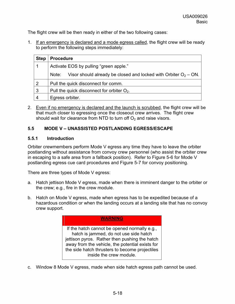
USA009026 Basic
5-18
The flight crew will be then ready in either of the two following cases:
1. If an emergency is declared and a mode egress called, the flight crew will be ready to perform the following steps immediately:
Step Procedure 1 Activate EOS by pulling �green apple.�
Note: Visor should already be closed and locked with Orbiter O2 � ON.
2 Pull the quick disconnect for comm. 3 Pull the quick disconnect for orbiter O2. 4 Egress orbiter.
2. Even if no emergency is declared and the launch is scrubbed, the flight crew will be that much closer to egressing once the closeout crew arrives. The flight crew should wait for clearance from NTD to turn off O2 and raise visors.
5.5 MODE V � UNASSISTED POSTLANDING EGRESS/ESCAPE
5.5.1 Introduction
Orbiter crewmembers perform Mode V egress any time they have to leave the orbiter postlanding without assistance from convoy crew personnel (who assist the orbiter crew in escaping to a safe area from a fallback position). Refer to Figure 5-6 for Mode V postlanding egress cue card procedures and Figure 5-7 for convoy positioning.
There are three types of Mode V egress:
a. Hatch jettison Mode V egress, made when there is imminent danger to the orbiter or the crew; e.g., fire in the crew module.
b. Hatch on Mode V egress, made when egress has to be expedited because of a hazardous condition or when the landing occurs at a landing site that has no convoy crew support.
WARNING
If the hatch cannot be opened normally e.g., hatch is jammed, do not use side hatch
jettison pyros. Rather then pushing the hatch away from the vehicle, the potential exists for the side hatch thrusters to become projectiles
inside the crew module.
c. Window 8 Mode V egress, made when side hatch egress path cannot be used.
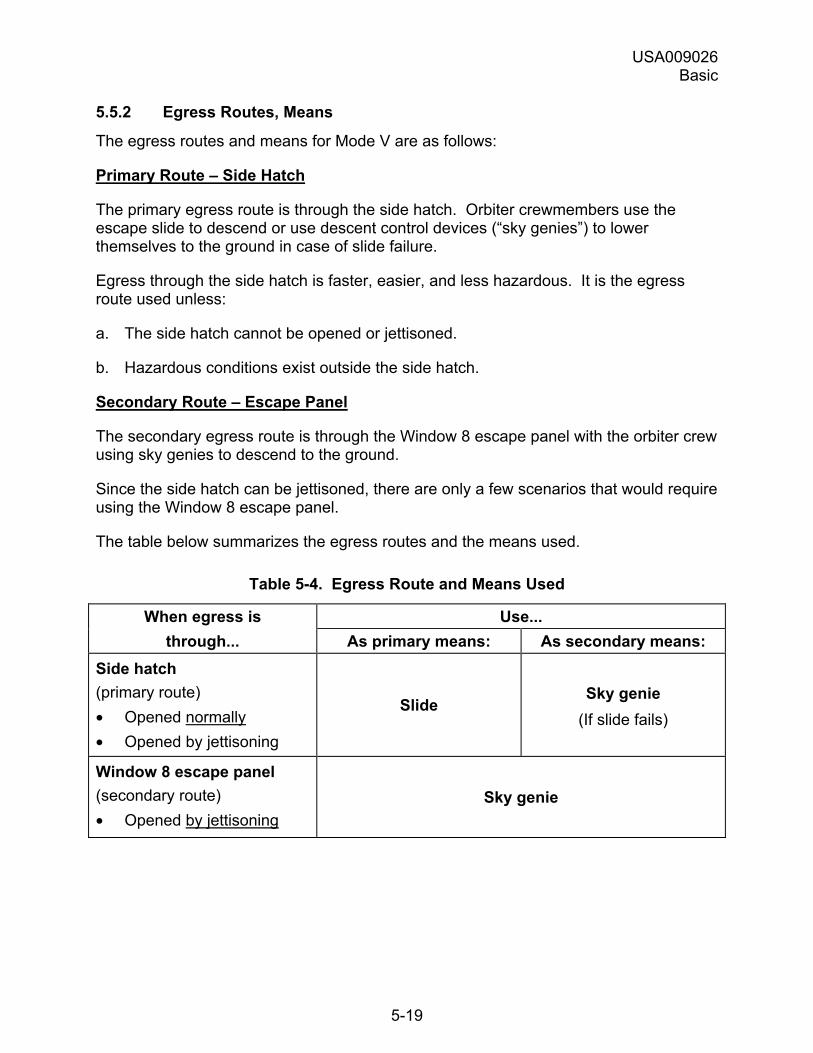
USA009026 Basic
5-19
5.5.2 Egress Routes, Means
The egress routes and means for Mode V are as follows:
Primary Route � Side Hatch
The primary egress route is through the side hatch. Orbiter crewmembers use the escape slide to descend or use descent control devices (�sky genies�) to lower themselves to the ground in case of slide failure.
Egress through the side hatch is faster, easier, and less hazardous. It is the egress route used unless:
a. The side hatch cannot be opened or jettisoned.
b. Hazardous conditions exist outside the side hatch.
Secondary Route � Escape Panel
The secondary egress route is through the Window 8 escape panel with the orbiter crew using sky genies to descend to the ground.
Since the side hatch can be jettisoned, there are only a few scenarios that would require using the Window 8 escape panel.
The table below summarizes the egress routes and the means used.
Table 5-4. Egress Route and Means Used
When egress is Use... through... As primary means: As secondary means:
Side hatch (primary route) • Opened normally • Opened by jettisoning
Slide Sky genie
(If slide fails)
Window 8 escape panel (secondary route) • Opened by jettisoning
Sky genie
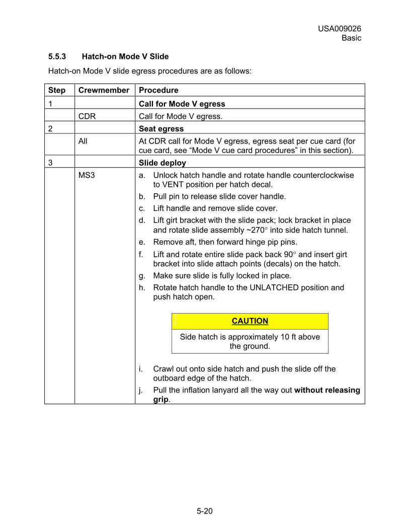
USA009026 Basic
5-20
5.5.3 Hatch-on Mode V Slide
Hatch-on Mode V slide egress procedures are as follows:
Step Crewmember Procedure 1 Call for Mode V egress CDR Call for Mode V egress. 2 Seat egress All At CDR call for Mode V egress, egress seat per cue card (for
cue card, see �Mode V cue card procedures� in this section). 3 Slide deploy MS3
a. Unlock hatch handle and rotate handle counterclockwise to VENT position per hatch decal.
b. Pull pin to release slide cover handle. c. Lift handle and remove slide cover. d. Lift girt bracket with the slide pack; lock bracket in place
and rotate slide assembly ~270° into side hatch tunnel. e. Remove aft, then forward hinge pip pins. f. Lift and rotate entire slide pack back 90° and insert girt
bracket into slide attach points (decals) on the hatch. g. Make sure slide is fully locked in place. h. Rotate hatch handle to the UNLATCHED position and
push hatch open.
CAUTION
Side hatch is approximately 10 ft above the ground.
i. Crawl out onto side hatch and push the slide off the outboard edge of the hatch.
j. Pull the inflation lanyard all the way out without releasing grip.
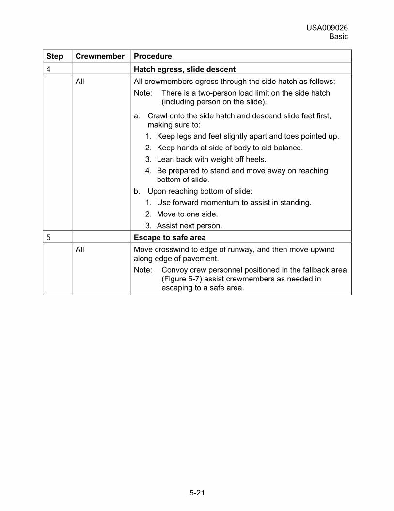
USA009026 Basic
5-21
Step Crewmember Procedure 4 Hatch egress, slide descent All All crewmembers egress through the side hatch as follows:
Note: There is a two-person load limit on the side hatch (including person on the slide).
a. Crawl onto the side hatch and descend slide feet first, making sure to:
1. Keep legs and feet slightly apart and toes pointed up. 2. Keep hands at side of body to aid balance. 3. Lean back with weight off heels. 4. Be prepared to stand and move away on reaching
bottom of slide. b. Upon reaching bottom of slide:
1. Use forward momentum to assist in standing. 2. Move to one side. 3. Assist next person.
5 Escape to safe area All Move crosswind to edge of runway, and then move upwind
along edge of pavement. Note: Convoy crew personnel positioned in the fallback area
(Figure 5-7) assist crewmembers as needed in escaping to a safe area.
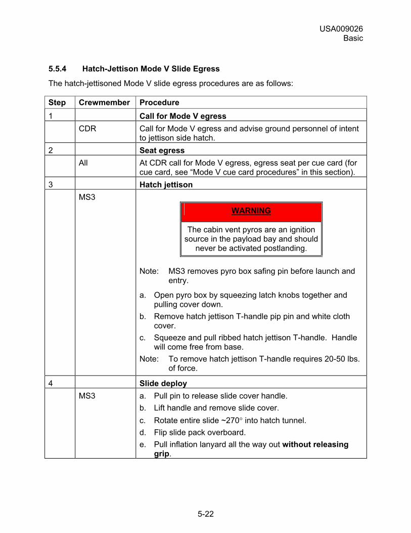
USA009026 Basic
5-22
5.5.4 Hatch-Jettison Mode V Slide Egress
The hatch-jettisoned Mode V slide egress procedures are as follows:
Step Crewmember Procedure 1 Call for Mode V egress CDR Call for Mode V egress and advise ground personnel of intent
to jettison side hatch. 2 Seat egress All At CDR call for Mode V egress, egress seat per cue card (for
cue card, see �Mode V cue card procedures� in this section). 3 Hatch jettison MS3
WARNING
The cabin vent pyros are an ignition source in the payload bay and should
never be activated postlanding.
Note: MS3 removes pyro box safing pin before launch and entry.
a. Open pyro box by squeezing latch knobs together and pulling cover down.
b. Remove hatch jettison T-handle pip pin and white cloth cover.
c. Squeeze and pull ribbed hatch jettison T-handle. Handle will come free from base.
Note: To remove hatch jettison T-handle requires 20-50 lbs. of force.
4 Slide deploy MS3 a. Pull pin to release slide cover handle.
b. Lift handle and remove slide cover. c. Rotate entire slide ~270° into hatch tunnel. d. Flip slide pack overboard. e. Pull inflation lanyard all the way out without releasing
grip.
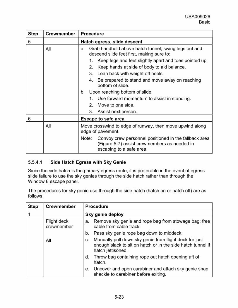
USA009026 Basic
5-23
Step Crewmember Procedure 5 Hatch egress, slide descent All a. Grab handhold above hatch tunnel; swing legs out and
descend slide feet first, making sure to: 1. Keep legs and feet slightly apart and toes pointed up. 2. Keep hands at side of body to aid balance. 3. Lean back with weight off heels. 4. Be prepared to stand and move away on reaching
bottom of slide. b. Upon reaching bottom of slide:
1. Use forward momentum to assist in standing. 2. Move to one side. 3. Assist next person.
6 Escape to safe area All Move crosswind to edge of runway, then move upwind along
edge of pavement. Note: Convoy crew personnel positioned in the fallback area
(Figure 5-7) assist crewmembers as needed in escaping to a safe area.
5.5.4.1 Side Hatch Egress with Sky Genie
Since the side hatch is the primary egress route, it is preferable in the event of egress slide failure to use the sky genies through the side hatch rather than through the Window 8 escape panel.
The procedures for sky genie use through the side hatch (hatch on or hatch off) are as follows:
Step Crewmember Procedure 1 Sky genie deploy Flight deck
crewmember All
a. Remove sky genie and rope bag from stowage bag; free cable from cable track.
b. Pass sky genie rope bag down to middeck. c. Manually pull down sky genie from flight deck for just
enough slack to sit on hatch or in the side hatch tunnel if hatch jettisoned.
d. Throw bag containing rope out hatch opening aft of hatch.
e. Uncover and open carabiner and attach sky genie snap shackle to carabiner before exiting.
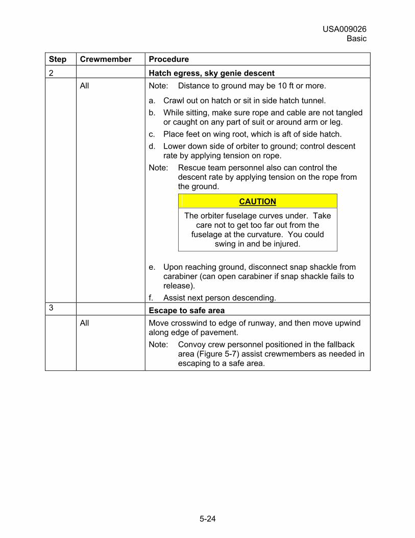
USA009026 Basic
5-24
Step Crewmember Procedure 2 Hatch egress, sky genie descent All Note: Distance to ground may be 10 ft or more.
a. Crawl out on hatch or sit in side hatch tunnel. b. While sitting, make sure rope and cable are not tangled
or caught on any part of suit or around arm or leg. c. Place feet on wing root, which is aft of side hatch. d. Lower down side of orbiter to ground; control descent
rate by applying tension on rope. Note: Rescue team personnel also can control the
descent rate by applying tension on the rope from the ground.
CAUTION The orbiter fuselage curves under. Take
care not to get too far out from the fuselage at the curvature. You could
swing in and be injured.
e. Upon reaching ground, disconnect snap shackle from carabiner (can open carabiner if snap shackle fails to release).
f. Assist next person descending. 3 Escape to safe area All Move crosswind to edge of runway, and then move upwind
along edge of pavement. Note: Convoy crew personnel positioned in the fallback
area (Figure 5-7) assist crewmembers as needed in escaping to a safe area.
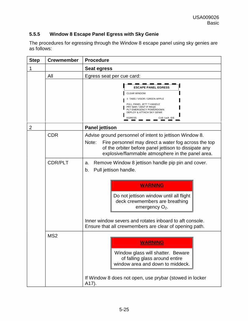
USA009026 Basic
5-25
5.5.5 Window 8 Escape Panel Egress with Sky Genie
The procedures for egressing through the Window 8 escape panel using sky genies are as follows:
Step Crewmember Procedure 1 Seat egress All Egress seat per cue card:
ESCAPE PANEL EGRESS
CLEAR WINDOW
TABS / VISOR / GREEN APPLE PULL PANEL JETT T-HANDLE PRY BAR / VENT IF REQD PLT EMERGENCY POWERDOWN DEPLOY & ATTACH SKY GENIE EGRESS CUE-1a/A, E/E
2 Panel jettison CDR Advise ground personnel of intent to jettison Window 8.
Note: Fire personnel may direct a water fog across the top of the orbiter before panel jettison to dissipate any explosive/flammable atmosphere in the panel area.
CDR/PLT a. Remove Window 8 jettison handle pip pin and cover. b. Pull jettison handle.
WARNING
Do not jettison window until all flight deck crewmembers are breathing
emergency O2.
Inner window severs and rotates inboard to aft console. Ensure that all crewmembers are clear of opening path.
MS2 WARNING
Window glass will shatter. Beware of falling glass around entire
window area and down to middeck.
If Window 8 does not open, use prybar (stowed in locker A17).
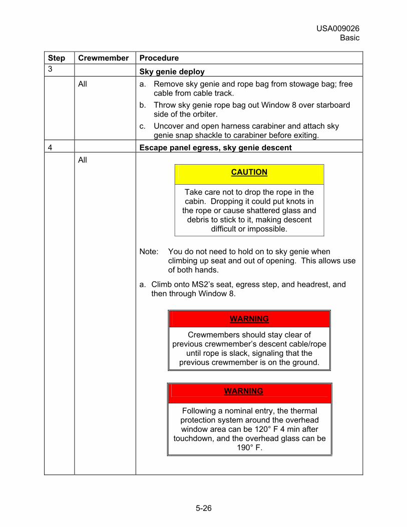
USA009026 Basic
5-26
Step Crewmember Procedure 3 Sky genie deploy All a. Remove sky genie and rope bag from stowage bag; free
cable from cable track. b. Throw sky genie rope bag out Window 8 over starboard
side of the orbiter. c. Uncover and open harness carabiner and attach sky
genie snap shackle to carabiner before exiting. 4 Escape panel egress, sky genie descent All
CAUTION
Take care not to drop the rope in the cabin. Dropping it could put knots in
the rope or cause shattered glass and debris to stick to it, making descent
difficult or impossible.
Note: You do not need to hold on to sky genie when climbing up seat and out of opening. This allows use of both hands.
a. Climb onto MS2�s seat, egress step, and headrest, and then through Window 8.
WARNING
Crewmembers should stay clear of previous crewmember�s descent cable/rope
until rope is slack, signaling that the previous crewmember is on the ground.
WARNING
Following a nominal entry, the thermal protection system around the overhead window area can be 120° F 4 min after
touchdown, and the overhead glass can be 190° F.
USA009026 Basic
5-27
Step Crewmember Procedure b. While sitting on windowsill, make sure rope and cable are
not tangled or caught on any part of suit or around arm or leg.
c. Hold onto sky genie hand loop with left hand and onto loose end of rope with right hand.
d. On your left side, slide down starboard side of orbiter until sky genie cable and rope are taut.
e. Proceed to lower down starboard side of orbiter, controlling descent rate by applying tension on the rope.
Note: Rescue team personnel also can control the descent rate by applying tension on the rope from the ground.
f. Upon reaching ground, disconnect snap shackle from carabiner (can open carabiner if snap shackle fails to release).
g. Assist next person descending. 5 Escape to safe area All Move crosswind to edge of runway, and then move upwind
along edge of pavement. Note: Convoy crew personnel positioned in the fallback
area (Figure 5-7) assist crewmembers as needed in escaping to a safe area.
5.5.6 Mode V Cue Card Procedures
The emergency egress cue card is shown below with the Mode V postlanding egress procedures highlighted (Figure 5-5).
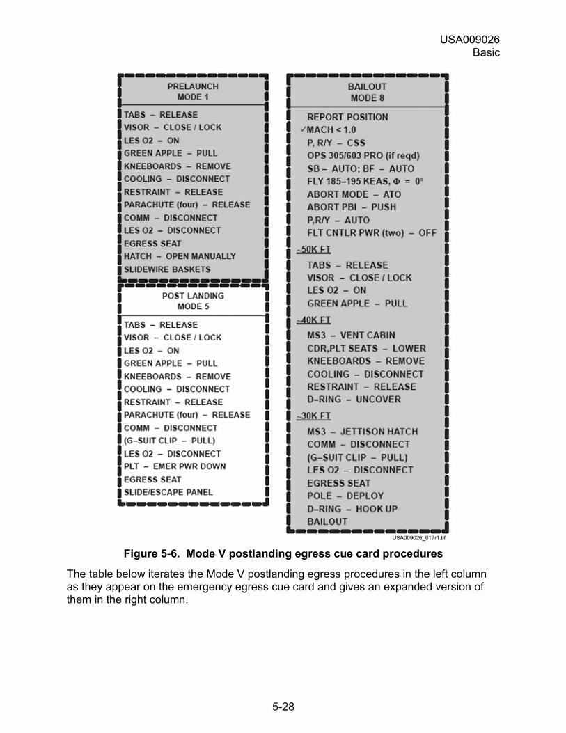
USA009026 Basic
5-28
Figure 5-6. Mode V postlanding egress cue card procedures
The table below iterates the Mode V postlanding egress procedures in the left column as they appear on the emergency egress cue card and gives an expanded version of them in the right column.
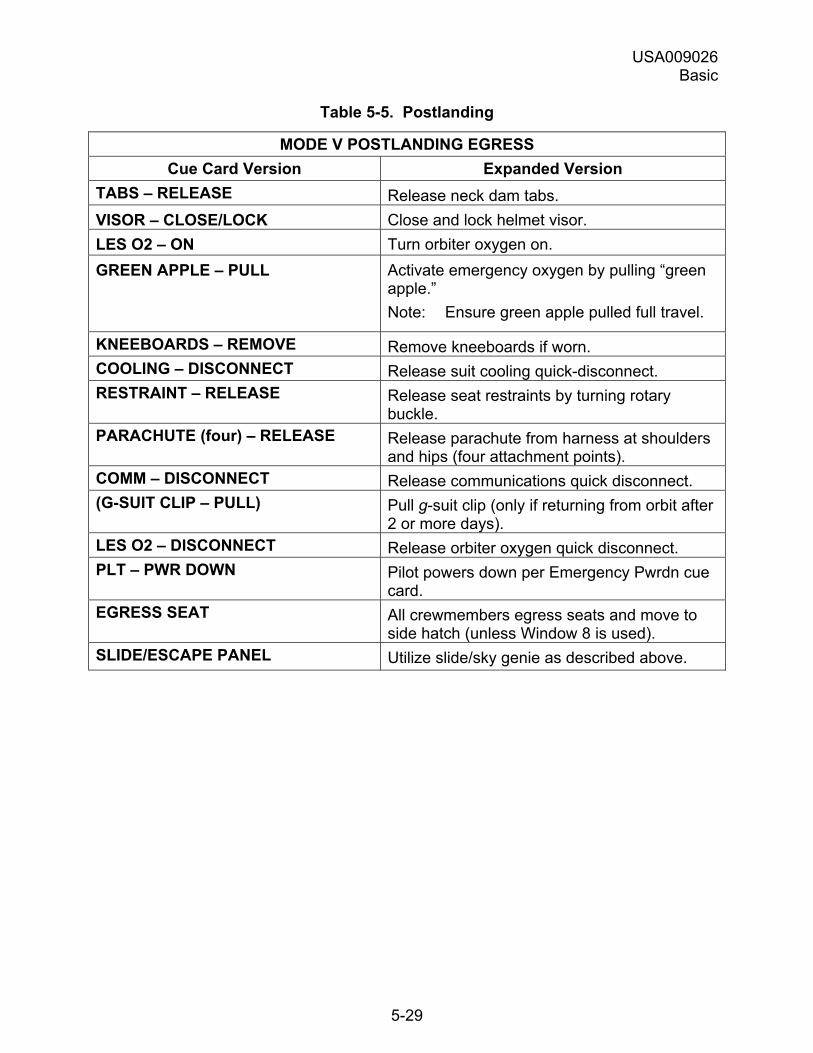
USA009026 Basic
5-29
Table 5-5. Postlanding
MODE V POSTLANDING EGRESS Cue Card Version Expanded Version
TABS � RELEASE Release neck dam tabs. VISOR � CLOSE/LOCK Close and lock helmet visor. LES O2 � ON Turn orbiter oxygen on. GREEN APPLE � PULL Activate emergency oxygen by pulling �green
apple.� Note: Ensure green apple pulled full travel.
KNEEBOARDS � REMOVE Remove kneeboards if worn. COOLING � DISCONNECT Release suit cooling quick-disconnect. RESTRAINT � RELEASE Release seat restraints by turning rotary
buckle. PARACHUTE (four) � RELEASE Release parachute from harness at shoulders
and hips (four attachment points). COMM � DISCONNECT Release communications quick disconnect. (G-SUIT CLIP � PULL) Pull g-suit clip (only if returning from orbit after
2 or more days). LES O2 � DISCONNECT Release orbiter oxygen quick disconnect. PLT � PWR DOWN Pilot powers down per Emergency Pwrdn cue
card. EGRESS SEAT All crewmembers egress seats and move to
side hatch (unless Window 8 is used). SLIDE/ESCAPE PANEL Utilize slide/sky genie as described above.
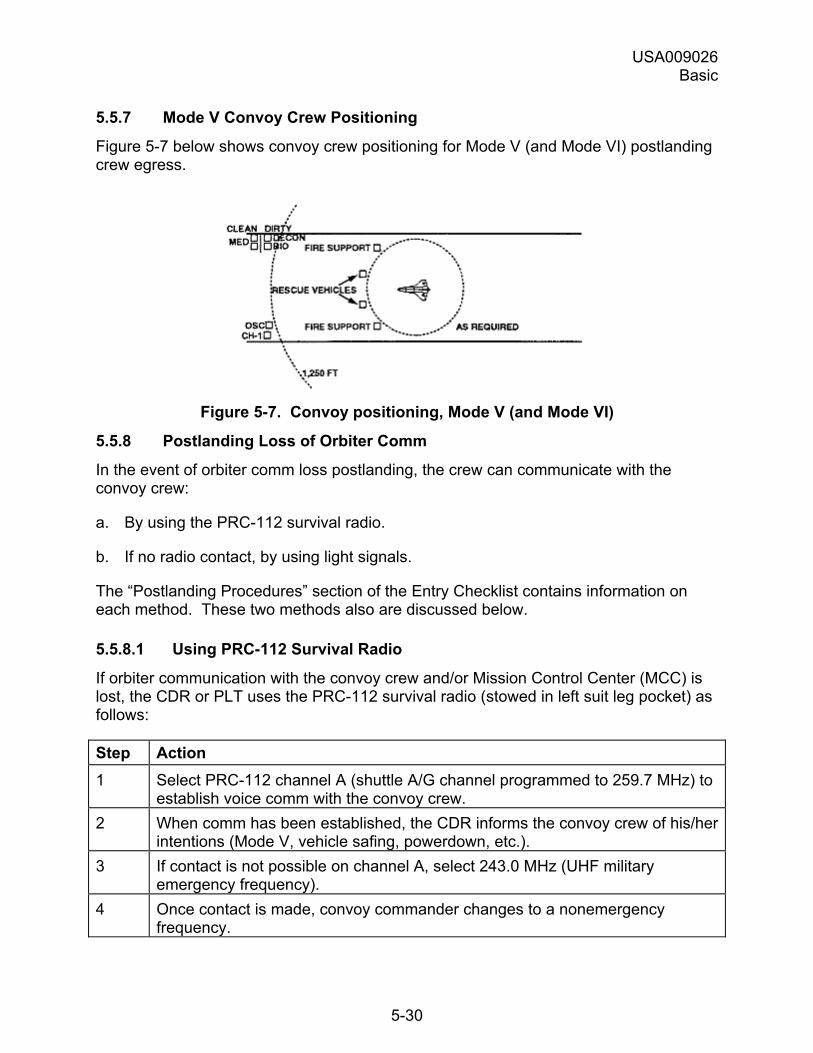
USA009026 Basic
5-30
5.5.7 Mode V Convoy Crew Positioning
Figure 5-7 below shows convoy crew positioning for Mode V (and Mode VI) postlanding crew egress.
Figure 5-7. Convoy positioning, Mode V (and Mode VI)
5.5.8 Postlanding Loss of Orbiter Comm
In the event of orbiter comm loss postlanding, the crew can communicate with the convoy crew:
a. By using the PRC-112 survival radio.
b. If no radio contact, by using light signals.
The �Postlanding Procedures� section of the Entry Checklist contains information on each method. These two methods also are discussed below.
5.5.8.1 Using PRC-112 Survival Radio
If orbiter communication with the convoy crew and/or Mission Control Center (MCC) is lost, the CDR or PLT uses the PRC-112 survival radio (stowed in left suit leg pocket) as follows:
Step Action 1 Select PRC-112 channel A (shuttle A/G channel programmed to 259.7 MHz) to
establish voice comm with the convoy crew. 2 When comm has been established, the CDR informs the convoy crew of his/her
intentions (Mode V, vehicle safing, powerdown, etc.). 3 If contact is not possible on channel A, select 243.0 MHz (UHF military
emergency frequency). 4 Once contact is made, convoy commander changes to a nonemergency
frequency.
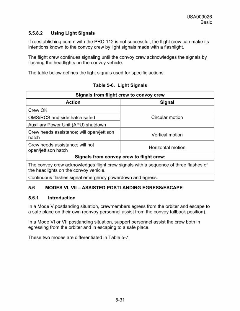
USA009026 Basic
5-31
5.5.8.2 Using Light Signals
If reestablishing comm with the PRC-112 is not successful, the flight crew can make its intentions known to the convoy crew by light signals made with a flashlight.
The flight crew continues signaling until the convoy crew acknowledges the signals by flashing the headlights on the convoy vehicle.
The table below defines the light signals used for specific actions.
Table 5-6. Light Signals
Signals from flight crew to convoy crew Action Signal
Crew OK OMS/RCS and side hatch safed Auxiliary Power Unit (APU) shutdown
Circular motion
Crew needs assistance; will open/jettison hatch Vertical motion
Crew needs assistance; will not open/jettison hatch Horizontal motion
Signals from convoy crew to flight crew: The convoy crew acknowledges flight crew signals with a sequence of three flashes of the headlights on the convoy vehicle. Continuous flashes signal emergency powerdown and egress.
5.6 MODES VI, VII � ASSISTED POSTLANDING EGRESS/ESCAPE
5.6.1 Introduction
In a Mode V postlanding situation, crewmembers egress from the orbiter and escape to a safe place on their own (convoy personnel assist from the convoy fallback position).
In a Mode VI or VII postlanding situation, support personnel assist the crew both in egressing from the orbiter and in escaping to a safe place.
These two modes are differentiated in Table 5-7.
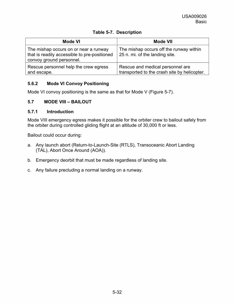
USA009026 Basic
5-32
Table 5-7. Description
Mode VI Mode VII The mishap occurs on or near a runway that is readily accessible to pre-positioned convoy ground personnel.
The mishap occurs off the runway within 25 n. mi. of the landing site.
Rescue personnel help the crew egress and escape.
Rescue and medical personnel are transported to the crash site by helicopter.
5.6.2 Mode VI Convoy Positioning
Mode VI convoy positioning is the same as that for Mode V (Figure 5-7).
5.7 MODE VIII � BAILOUT
5.7.1 Introduction
Mode VIII emergency egress makes it possible for the orbiter crew to bailout safely from the orbiter during controlled gliding flight at an altitude of 30,000 ft or less.
Bailout could occur during:
a. Any launch abort (Return-to-Launch-Site (RTLS), Transoceanic Abort Landing (TAL), Abort Once Around (AOA)).
b. Emergency deorbit that must be made regardless of landing site.
c. Any failure precluding a normal landing on a runway.
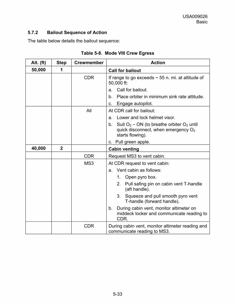
USA009026 Basic
5-33
5.7.2 Bailout Sequence of Action
The table below details the bailout sequence:
Table 5-8. Mode VIII Crew Egress
Alt. (ft) Step Crewmember Action 50,000 1 Call for bailout
CDR If range to go exceeds ~ 55 n. mi. at altitude of 50,000 ft: a. Call for bailout. b. Place orbiter in minimum sink rate attitude. c. Engage autopilot.
All At CDR call for bailout: a. Lower and lock helmet visor. b. Suit O2 � ON (to breathe orbiter O2 until
quick disconnect, when emergency O2 starts flowing).
c. Pull green apple. 40,000 2 Cabin venting
CDR Request MS3 to vent cabin. MS3 At CDR request to vent cabin:
a. Vent cabin as follows: 1. Open pyro box. 2. Pull safing pin on cabin vent T-handle
(aft handle). 3. Squeeze and pull smooth pyro vent
T-handle (forward handle). b. During cabin vent, monitor altimeter on
middeck locker and communicate reading to CDR.
CDR During cabin vent, monitor altimeter reading and communicate reading to MS3.
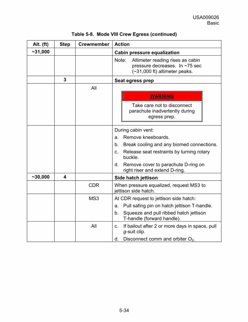
USA009026 Basic
5-34
Table 5-8. Mode VIII Crew Egress (continued)
Alt. (ft) Step Crewmember Action ~31,000 Cabin pressure equalization
Note: Altimeter reading rises as cabin pressure decreases. In ~75 sec (~31,000 ft) altimeter peaks.
3 Seat egress prep All
WARNING
Take care not to disconnect parachute inadvertently during
egress prep.
During cabin vent: a. Remove kneeboards. b. Break cooling and any biomed connections. c. Release seat restraints by turning rotary
buckle. d. Remove cover to parachute D-ring on
right riser and extend D-ring. ~30,000 4 Side hatch jettison
CDR When pressure equalized, request MS3 to jettison side hatch.
MS3 At CDR request to jettison side hatch: a. Pull safing pin on hatch jettison T-handle. b. Squeeze and pull ribbed hatch jettison
T-handle (forward handle). All c. If bailout after 2 or more days in space, pull
g-suit clip. d. Disconnect comm and orbiter O2.
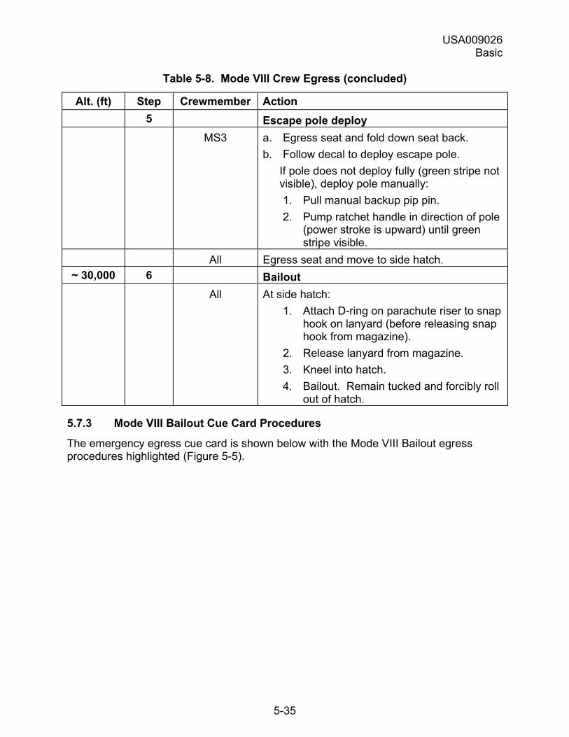
USA009026 Basic
5-35
Table 5-8. Mode VIII Crew Egress (concluded)
Alt. (ft) Step Crewmember Action 5 Escape pole deploy MS3 a. Egress seat and fold down seat back.
b. Follow decal to deploy escape pole. If pole does not deploy fully (green stripe not visible), deploy pole manually: 1. Pull manual backup pip pin. 2. Pump ratchet handle in direction of pole
(power stroke is upward) until green stripe visible.
All Egress seat and move to side hatch. ~ 30,000 6 Bailout
All At side hatch: 1. Attach D-ring on parachute riser to snap
hook on lanyard (before releasing snap hook from magazine).
2. Release lanyard from magazine. 3. Kneel into hatch. 4. Bailout. Remain tucked and forcibly roll
out of hatch.
5.7.3 Mode VIII Bailout Cue Card Procedures
The emergency egress cue card is shown below with the Mode VIII Bailout egress procedures highlighted (Figure 5-5).
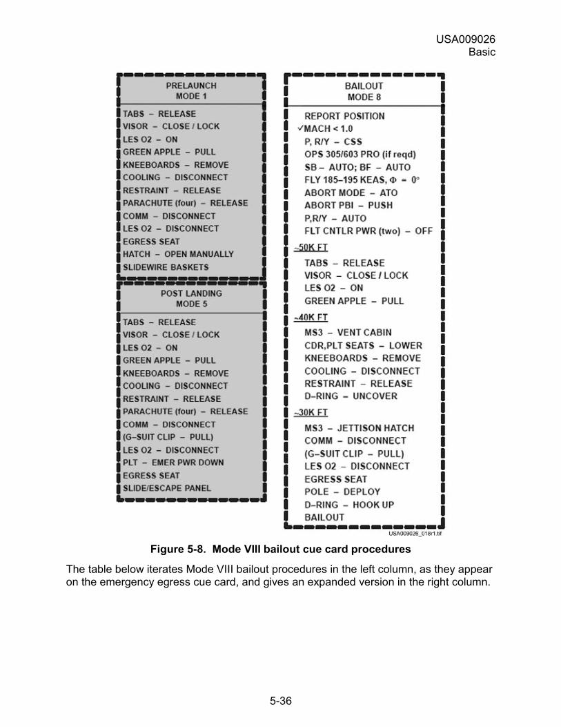
USA009026 Basic
5-36
Figure 5-8. Mode VIII bailout cue card procedures
The table below iterates Mode VIII bailout procedures in the left column, as they appear on the emergency egress cue card, and gives an expanded version in the right column.
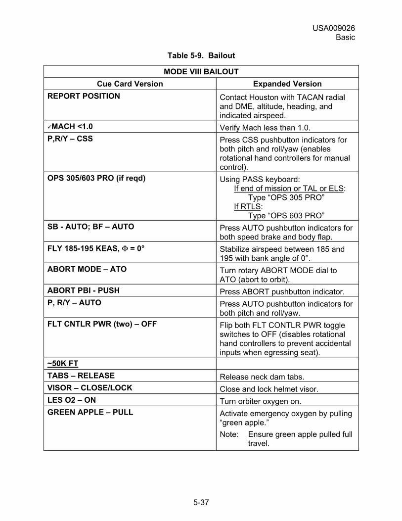
USA009026 Basic
5-37
Table 5-9. Bailout
MODE VIII BAILOUT Cue Card Version Expanded Version
REPORT POSITION Contact Houston with TACAN radial and DME, altitude, heading, and indicated airspeed.
!MACH <1.0 Verify Mach less than 1.0. P,R/Y � CSS Press CSS pushbutton indicators for
both pitch and roll/yaw (enables rotational hand controllers for manual control).
OPS 305/603 PRO (if reqd) Using PASS keyboard: If end of mission or TAL or ELS:
Type �OPS 305 PRO� If RTLS:
Type �OPS 603 PRO� SB - AUTO; BF � AUTO Press AUTO pushbutton indicators for
both speed brake and body flap. FLY 185-195 KEAS, Φ = 0° Stabilize airspeed between 185 and
195 with bank angle of 0°. ABORT MODE � ATO Turn rotary ABORT MODE dial to
ATO (abort to orbit). ABORT PBI - PUSH Press ABORT pushbutton indicator. P, R/Y � AUTO Press AUTO pushbutton indicators for
both pitch and roll/yaw. FLT CNTLR PWR (two) � OFF Flip both FLT CONTLR PWR toggle
switches to OFF (disables rotational hand controllers to prevent accidental inputs when egressing seat).
~50K FT TABS � RELEASE Release neck dam tabs. VISOR � CLOSE/LOCK Close and lock helmet visor. LES O2 � ON Turn orbiter oxygen on. GREEN APPLE � PULL Activate emergency oxygen by pulling
�green apple.� Note: Ensure green apple pulled full
travel.
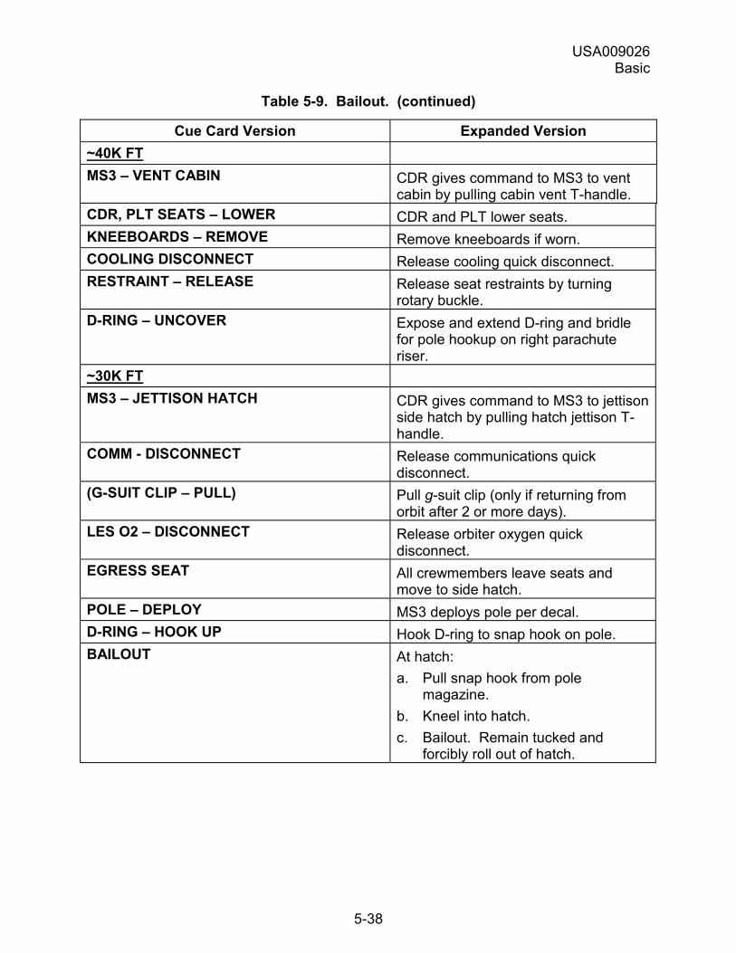
USA009026 Basic
5-38
Table 5-9. Bailout. (continued)
Cue Card Version Expanded Version ~40K FT MS3 � VENT CABIN CDR gives command to MS3 to vent
cabin by pulling cabin vent T-handle. CDR, PLT SEATS � LOWER CDR and PLT lower seats. KNEEBOARDS � REMOVE Remove kneeboards if worn. COOLING DISCONNECT Release cooling quick disconnect. RESTRAINT � RELEASE Release seat restraints by turning
rotary buckle. D-RING � UNCOVER Expose and extend D-ring and bridle
for pole hookup on right parachute riser.
~30K FT MS3 � JETTISON HATCH CDR gives command to MS3 to jettison
side hatch by pulling hatch jettison T-handle.
COMM - DISCONNECT Release communications quick disconnect.
(G-SUIT CLIP � PULL) Pull g-suit clip (only if returning from orbit after 2 or more days).
LES O2 � DISCONNECT Release orbiter oxygen quick disconnect.
EGRESS SEAT All crewmembers leave seats and move to side hatch.
POLE � DEPLOY MS3 deploys pole per decal. D-RING � HOOK UP Hook D-ring to snap hook on pole. BAILOUT At hatch:
a. Pull snap hook from pole magazine.
b. Kneel into hatch. c. Bailout. Remain tucked and
forcibly roll out of hatch.
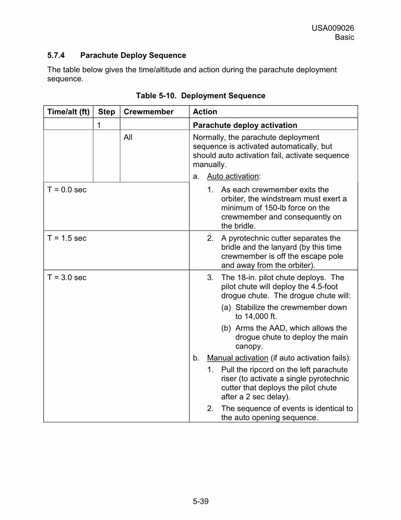
USA009026 Basic
5-39
5.7.4 Parachute Deploy Sequence
The table below gives the time/altitude and action during the parachute deployment sequence.
Table 5-10. Deployment Sequence
Time/alt (ft) Step Crewmember Action 1 Parachute deploy activation All Normally, the parachute deployment
sequence is activated automatically, but should auto activation fail, activate sequence manually. a. Auto activation:
T = 0.0 sec 1. As each crewmember exits the orbiter, the windstream must exert a minimum of 150-lb force on the crewmember and consequently on the bridle.
T = 1.5 sec 2. A pyrotechnic cutter separates the bridle and the lanyard (by this time crewmember is off the escape pole and away from the orbiter).
T = 3.0 sec 3. The 18-in. pilot chute deploys. The pilot chute will deploy the 4.5-foot drogue chute. The drogue chute will: (a) Stabilize the crewmember down
to 14,000 ft. (b) Arms the AAD, which allows the
drogue chute to deploy the main canopy.
b. Manual activation (if auto activation fails): 1. Pull the ripcord on the left parachute
riser (to activate a single pyrotechnic cutter that deploys the pilot chute after a 2 sec delay).
2. The sequence of events is identical to the auto opening sequence.
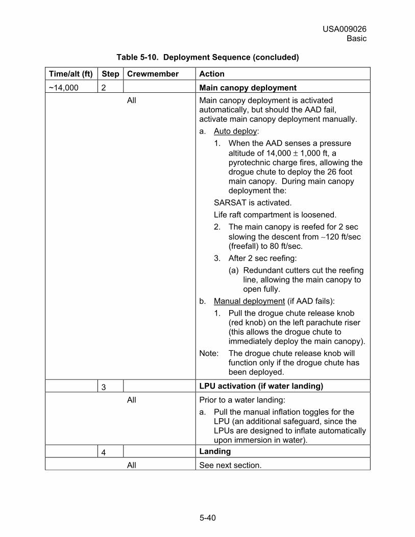
USA009026 Basic
5-40
Table 5-10. Deployment Sequence (concluded)
Time/alt (ft) Step Crewmember Action ~14,000 2 Main canopy deployment All Main canopy deployment is activated
automatically, but should the AAD fail, activate main canopy deployment manually. a. Auto deploy:
1. When the AAD senses a pressure altitude of 14,000 ± 1,000 ft, a pyrotechnic charge fires, allowing the drogue chute to deploy the 26 foot main canopy. During main canopy deployment the:
SARSAT is activated. Life raft compartment is loosened. 2. The main canopy is reefed for 2 sec
slowing the descent from ∼120 ft/sec (freefall) to 80 ft/sec.
3. After 2 sec reefing: (a) Redundant cutters cut the reefing
line, allowing the main canopy to open fully.
b. Manual deployment (if AAD fails): 1. Pull the drogue chute release knob
(red knob) on the left parachute riser (this allows the drogue chute to immediately deploy the main canopy).
Note: The drogue chute release knob will function only if the drogue chute has been deployed.
3 LPU activation (if water landing) All Prior to a water landing:
a. Pull the manual inflation toggles for the LPU (an additional safeguard, since the LPUs are designed to inflate automatically upon immersion in water).
4 Landing All See next section.
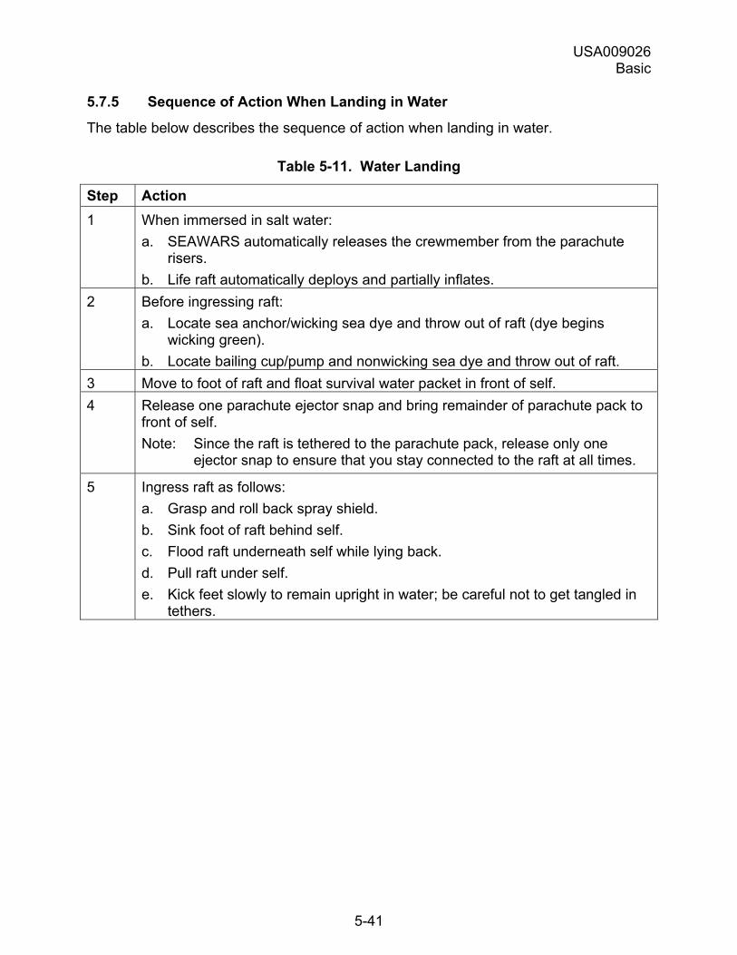
USA009026 Basic
5-41
5.7.5 Sequence of Action When Landing in Water
The table below describes the sequence of action when landing in water.
Table 5-11. Water Landing
Step Action 1 When immersed in salt water:
a. SEAWARS automatically releases the crewmember from the parachute risers.
b. Life raft automatically deploys and partially inflates. 2 Before ingressing raft:
a. Locate sea anchor/wicking sea dye and throw out of raft (dye begins wicking green).
b. Locate bailing cup/pump and nonwicking sea dye and throw out of raft. 3 Move to foot of raft and float survival water packet in front of self. 4 Release one parachute ejector snap and bring remainder of parachute pack to
front of self. Note: Since the raft is tethered to the parachute pack, release only one
ejector snap to ensure that you stay connected to the raft at all times.
5 Ingress raft as follows: a. Grasp and roll back spray shield. b. Sink foot of raft behind self. c. Flood raft underneath self while lying back. d. Pull raft under self. e. Kick feet slowly to remain upright in water; be careful not to get tangled in
tethers.
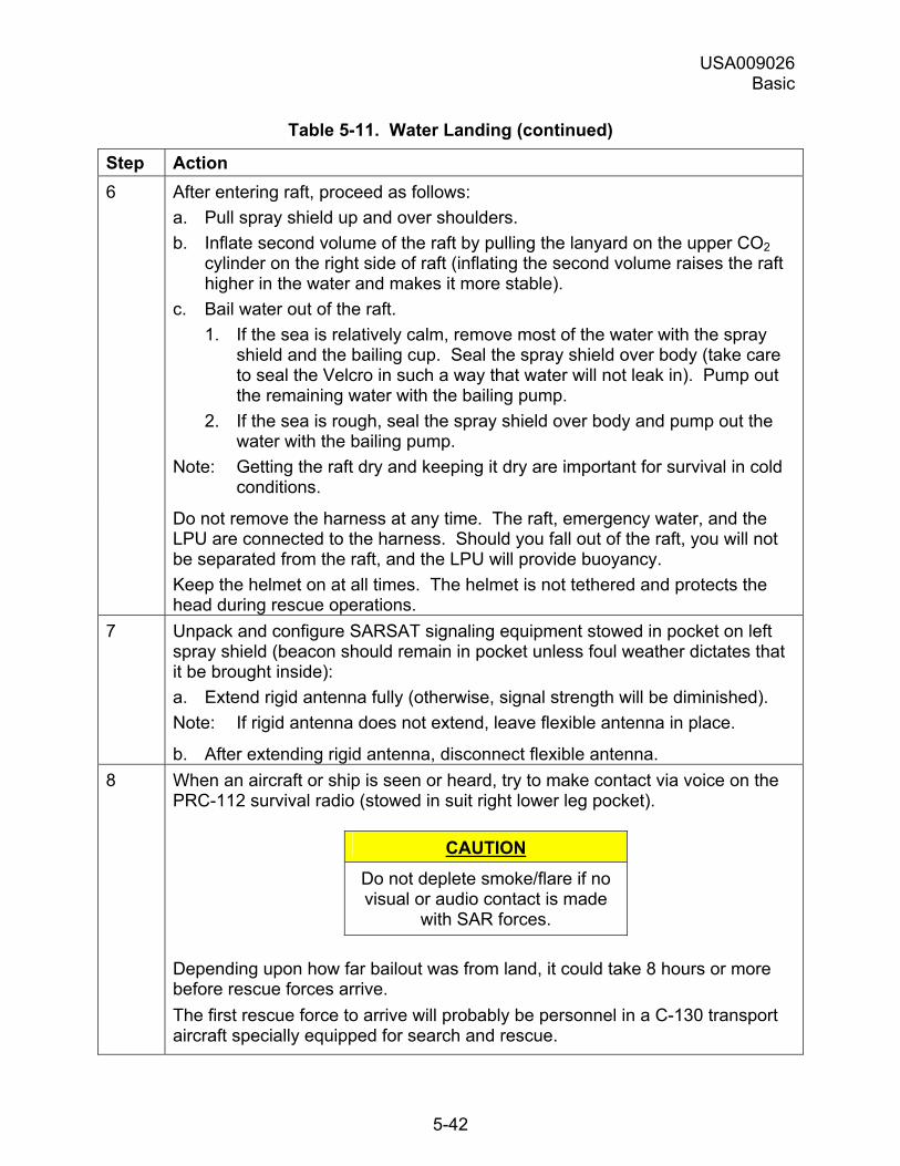
USA009026 Basic
5-42
Table 5-11. Water Landing (continued)
Step Action 6 After entering raft, proceed as follows:
a. Pull spray shield up and over shoulders. b. Inflate second volume of the raft by pulling the lanyard on the upper CO2
cylinder on the right side of raft (inflating the second volume raises the raft higher in the water and makes it more stable).
c. Bail water out of the raft. 1. If the sea is relatively calm, remove most of the water with the spray
shield and the bailing cup. Seal the spray shield over body (take care to seal the Velcro in such a way that water will not leak in). Pump out the remaining water with the bailing pump.
2. If the sea is rough, seal the spray shield over body and pump out the water with the bailing pump.
Note: Getting the raft dry and keeping it dry are important for survival in cold conditions.
Do not remove the harness at any time. The raft, emergency water, and the LPU are connected to the harness. Should you fall out of the raft, you will not be separated from the raft, and the LPU will provide buoyancy. Keep the helmet on at all times. The helmet is not tethered and protects the head during rescue operations.
7 Unpack and configure SARSAT signaling equipment stowed in pocket on left spray shield (beacon should remain in pocket unless foul weather dictates that it be brought inside): a. Extend rigid antenna fully (otherwise, signal strength will be diminished). Note: If rigid antenna does not extend, leave flexible antenna in place.
b. After extending rigid antenna, disconnect flexible antenna. 8 When an aircraft or ship is seen or heard, try to make contact via voice on the
PRC-112 survival radio (stowed in suit right lower leg pocket).
CAUTION Do not deplete smoke/flare if no visual or audio contact is made
with SAR forces.
Depending upon how far bailout was from land, it could take 8 hours or more before rescue forces arrive. The first rescue force to arrive will probably be personnel in a C-130 transport aircraft specially equipped for search and rescue.
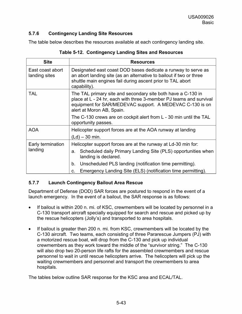
USA009026 Basic
5-43
5.7.6 Contingency Landing Site Resources
The table below describes the resources available at each contingency landing site.
Table 5-12. Contingency Landing Sites and Resources
Site Resources East coast abort landing sites
Designated east coast DOD bases dedicate a runway to serve as an abort landing site (as an alternative to bailout if two or three shuttle main engines fail during ascent prior to TAL abort capability).
TAL The TAL primary site and secondary site both have a C-130 in place at L - 24 hr, each with three 3-member PJ teams and survival equipment for SAR/MEDEVAC support. A MEDEVAC C-130 is on alert at Moron AB, Spain. The C-130 crews are on cockpit alert from L - 30 min until the TAL opportunity passes.
AOA Helicopter support forces are at the AOA runway at landing (Ld) � 30 min.
Early termination landing
Helicopter support forces are at the runway at Ld-30 min for: a. Scheduled daily Primary Landing Site (PLS) opportunities when
landing is declared. b. Unscheduled PLS landing (notification time permitting). c. Emergency Landing Site (ELS) (notification time permitting).
5.7.7 Launch Contingency Bailout Area Rescue
Department of Defense (DOD) SAR forces are postured to respond in the event of a launch emergency. In the event of a bailout, the SAR response is as follows:
• If bailout is within 200 n. mi. of KSC, crewmembers will be located by personnel in a C-130 transport aircraft specially equipped for search and rescue and picked up by the rescue helicopters (Jolly�s) and transported to area hospitals.
• If bailout is greater then 200 n. mi. from KSC, crewmembers will be located by the C-130 aircraft. Two teams, each consisting of three Pararescue Jumpers (PJ) with a motorized rescue boat, will drop from the C-130 and pick up individual crewmembers as they work toward the middle of the �survivor string.� The C-130 will also drop two 20-person life rafts for the assembled crewmembers and rescue personnel to wait in until rescue helicopters arrive. The helicopters will pick up the waiting crewmembers and personnel and transport the crewmembers to area hospitals.
The tables below outline SAR response for the KSC area and ECAL/TAL.
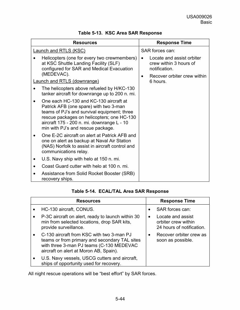
USA009026 Basic
5-44
Table 5-13. KSC Area SAR Response
Resources Response Time Launch and RTLS (KSC) • Helicopters (one for every two crewmembers)
at KSC Shuttle Landing Facility (SLF) configured for SAR and Medical Evacuation (MEDEVAC).
Launch and RTLS (downrange) • The helicopters above refueled by H/KC-130
tanker aircraft for downrange up to 200 n. mi. • One each HC-130 and KC-130 aircraft at
Patrick AFB (one spare) with two 3-man teams of PJ�s and survival equipment; three rescue packages on helicopters; one HC-130 aircraft 175 - 200 n. mi. downrange L - 10 min with PJ�s and rescue package.
• One E-2C aircraft on alert at Patrick AFB and one on alert as backup at Naval Air Station (NAS) Norfolk to assist in aircraft control and communications relay.
• U.S. Navy ship with helo at 150 n. mi. • Coast Guard cutter with helo at 100 n. mi. • Assistance from Solid Rocket Booster (SRB)
recovery ships.
SAR forces can: • Locate and assist orbiter
crew within 3 hours of notification.
• Recover orbiter crew within 6 hours.
Table 5-14. ECAL/TAL Area SAR Response
Resources Response Time
• HC-130 aircraft, CONUS. • P-3C aircraft on alert, ready to launch within 30
min from selected locations, drop SAR kits, provide surveillance.
• C-130 aircraft from KSC with two 3-man PJ teams or from primary and secondary TAL sites with three 3-man PJ teams (C-130 MEDEVAC aircraft on alert at Moron AB, Spain).
• U.S. Navy vessels, USCG cutters and aircraft, ships of opportunity used for recovery.
• SAR forces can: • Locate and assist
orbiter crew within 24 hours of notification.
• Recover orbiter crew as soon as possible.
All night rescue operations will be �best effort� by SAR forces.
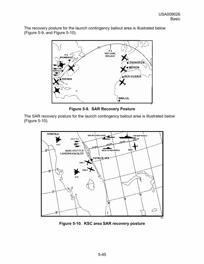
USA009026 Basic
5-45
The recovery posture for the launch contingency bailout area is illustrated below (Figure 5-9, and Figure 5-10).
Figure 5-9. SAR Recovery Posture
The SAR recovery posture for the launch contingency bailout area is illustrated below (Figure 5-10).
Figure 5-10. KSC area SAR recovery posture
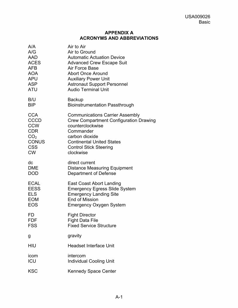
USA009026 Basic
A-1
APPENDIX A ACRONYMS AND ABBREVIATIONS
A/A Air to Air A/G Air to Ground AAD Automatic Actuation Device ACES Advanced Crew Escape Suit AFB Air Force Base AOA Abort Once Around APU Auxiliary Power Unit ASP Astronaut Support Personnel ATU Audio Terminal Unit
B/U Backup BIP Bioinstrumentation Passthrough
CCA Communications Carrier Assembly CCCD Crew Compartment Configuration Drawing CCW counterclockwise CDR Commander CO2 carbon dioxide CONUS Continental United States CSS Control Stick Steering CW clockwise
dc direct current DME Distance Measuring Equipment DOD Department of Defense
ECAL East Coast Abort Landing EESS Emergency Egress Slide System ELS Emergency Landing Site EOM End of Mission EOS Emergency Oxygen System
FD Fight Director FDF Fight Data File FSS Fixed Service Structure
g gravity
HIU Headset Interface Unit
icom intercom ICU Individual Cooling Unit
KSC Kennedy Space Center
USA009026 Basic
A-2
LCC Launch Control Center LCG Liquid Cooling Garment Ld landing LPU Life Preserver Unit LWS Lightweight Seat
MAR Middeck Accommodations Rack MCC Mission Control Center MEDEVAC Medical Evacuation MS Mission Specialist
n. mi. nautical mile NAS Naval Air Station NASA National Aeronautics and Space Administration NTD NASA Test Director
O2 oxygen O&C Operations and Checkout OAA Orbiter Access Arm
PBI Push Button Indicator PJ Pararescue Jumper PLS Primary Landing Site PLT Pilot PPA Personal Parachute Assembly PS Payload Specialist PSCS Personal Suit Cooling System psi pounds per square inch psia pounds per square inch absolute psig pounds per square inch gauge PTT Push to Talk
QD Quick Disconnect
RHC Rotational Hand Controller RSK Recumbent Seat Kit RTLS Return to Launch Site
S seat SAR Search and Rescue SARSAT Search and Rescue Satellite-Aided Tracking SEAWARS Seawater Activated Release System SLF Shuttle Landing Facility SRB Solid Rocket Booster SSME Space Shuttle Main Engine
USA009026 Basic
A-3
T time TACAN Tactical Air Navigation TAL Transatlantic Abort Landing TELCU Thermal Electric Liquid Cooling Unit
UHF Ultrahigh Frequency USCG United States Coast Guard USN United States Navy
V dc volts dc VLHS Very Lightweight Headset
w/helo with helicopter
xmit transmit
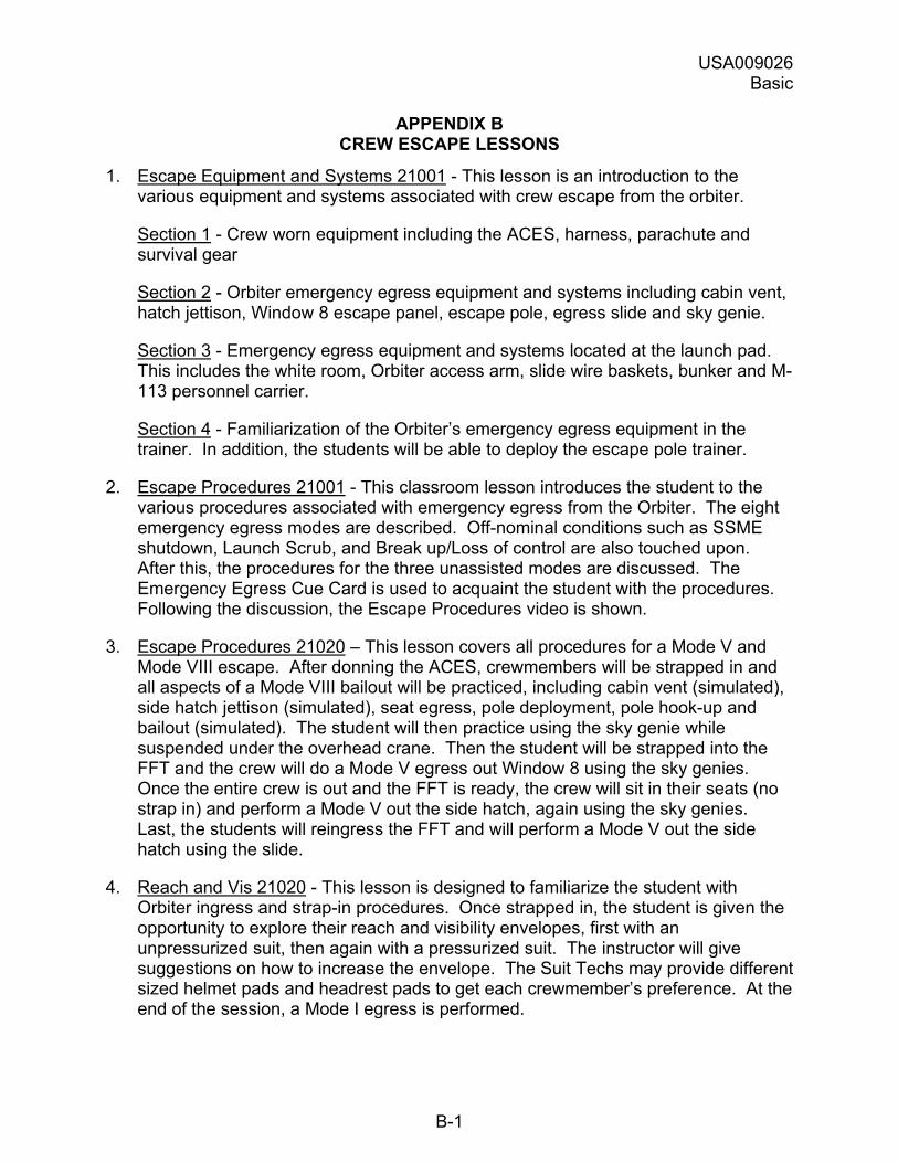
USA009026 Basic
B-1
APPENDIX B CREW ESCAPE LESSONS
1. Escape Equipment and Systems 21001 - This lesson is an introduction to the various equipment and systems associated with crew escape from the orbiter.
Section 1 - Crew worn equipment including the ACES, harness, parachute and survival gear
Section 2 - Orbiter emergency egress equipment and systems including cabin vent, hatch jettison, Window 8 escape panel, escape pole, egress slide and sky genie.
Section 3 - Emergency egress equipment and systems located at the launch pad. This includes the white room, Orbiter access arm, slide wire baskets, bunker and M-113 personnel carrier.
Section 4 - Familiarization of the Orbiter�s emergency egress equipment in the trainer. In addition, the students will be able to deploy the escape pole trainer.
2. Escape Procedures 21001 - This classroom lesson introduces the student to the various procedures associated with emergency egress from the Orbiter. The eight emergency egress modes are described. Off-nominal conditions such as SSME shutdown, Launch Scrub, and Break up/Loss of control are also touched upon. After this, the procedures for the three unassisted modes are discussed. The Emergency Egress Cue Card is used to acquaint the student with the procedures. Following the discussion, the Escape Procedures video is shown.
3. Escape Procedures 21020 � This lesson covers all procedures for a Mode V and Mode VIII escape. After donning the ACES, crewmembers will be strapped in and all aspects of a Mode VIII bailout will be practiced, including cabin vent (simulated), side hatch jettison (simulated), seat egress, pole deployment, pole hook-up and bailout (simulated). The student will then practice using the sky genie while suspended under the overhead crane. Then the student will be strapped into the FFT and the crew will do a Mode V egress out Window 8 using the sky genies. Once the entire crew is out and the FFT is ready, the crew will sit in their seats (no strap in) and perform a Mode V out the side hatch, again using the sky genies. Last, the students will reingress the FFT and will perform a Mode V out the side hatch using the slide.
4. Reach and Vis 21020 - This lesson is designed to familiarize the student with Orbiter ingress and strap-in procedures. Once strapped in, the student is given the opportunity to explore their reach and visibility envelopes, first with an unpressurized suit, then again with a pressurized suit. The instructor will give suggestions on how to increase the envelope. The Suit Techs may provide different sized helmet pads and headrest pads to get each crewmember�s preference. At the end of the session, a Mode I egress is performed.
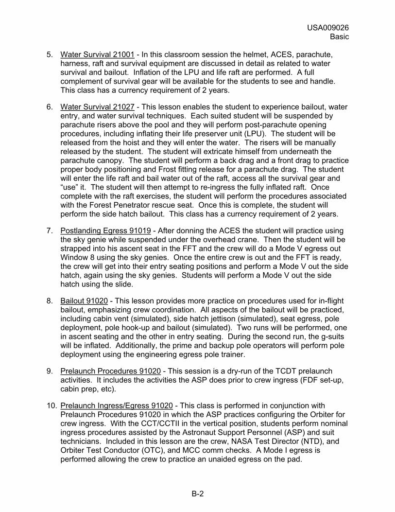
USA009026 Basic
B-2
5. Water Survival 21001 - In this classroom session the helmet, ACES, parachute, harness, raft and survival equipment are discussed in detail as related to water survival and bailout. Inflation of the LPU and life raft are performed. A full complement of survival gear will be available for the students to see and handle. This class has a currency requirement of 2 years.
6. Water Survival 21027 - This lesson enables the student to experience bailout, water entry, and water survival techniques. Each suited student will be suspended by parachute risers above the pool and they will perform post-parachute opening procedures, including inflating their life preserver unit (LPU). The student will be released from the hoist and they will enter the water. The risers will be manually released by the student. The student will extricate himself from underneath the parachute canopy. The student will perform a back drag and a front drag to practice proper body positioning and Frost fitting release for a parachute drag. The student will enter the life raft and bail water out of the raft, access all the survival gear and �use� it. The student will then attempt to re-ingress the fully inflated raft. Once complete with the raft exercises, the student will perform the procedures associated with the Forest Penetrator rescue seat. Once this is complete, the student will perform the side hatch bailout. This class has a currency requirement of 2 years.
7. Postlanding Egress 91019 - After donning the ACES the student will practice using the sky genie while suspended under the overhead crane. Then the student will be strapped into his ascent seat in the FFT and the crew will do a Mode V egress out Window 8 using the sky genies. Once the entire crew is out and the FFT is ready, the crew will get into their entry seating positions and perform a Mode V out the side hatch, again using the sky genies. Students will perform a Mode V out the side hatch using the slide.
8. Bailout 91020 - This lesson provides more practice on procedures used for in-flight bailout, emphasizing crew coordination. All aspects of the bailout will be practiced, including cabin vent (simulated), side hatch jettison (simulated), seat egress, pole deployment, pole hook-up and bailout (simulated). Two runs will be performed, one in ascent seating and the other in entry seating. During the second run, the g-suits will be inflated. Additionally, the prime and backup pole operators will perform pole deployment using the engineering egress pole trainer.
9. Prelaunch Procedures 91020 - This session is a dry-run of the TCDT prelaunch activities. It includes the activities the ASP does prior to crew ingress (FDF set-up, cabin prep, etc).
10. Prelaunch Ingress/Egress 91020 - This class is performed in conjunction with Prelaunch Procedures 91020 in which the ASP practices configuring the Orbiter for crew ingress. With the CCT/CCTII in the vertical position, students perform nominal ingress procedures assisted by the Astronaut Support Personnel (ASP) and suit technicians. Included in this lesson are the crew, NASA Test Director (NTD), and Orbiter Test Conductor (OTC), and MCC comm checks. A Mode I egress is performed allowing the crew to practice an unaided egress on the pad.

USA009026 Basic
B-3
11. Escape Refresher 41020 - This classroom lesson reviews the various procedures associated with emergency egress from the Orbiter. Off-nominal conditions such as SSME shutdown, Launch scrub, and Break up/Loss of Control are also touched on. The procedures for the three unassisted modes are discussed. The Emergency Egress Cue Card is used to review the procedures. The Escape Procedures video is shown. Prybar ops are reviewed in the CCT.
DOCUMENT NUMBER: USA009026Basic
TITLE: Crew Escape Systems 21002
NASA-JSC
AC Engle, J. CA4 Hanley, R. (6) CB Rominger, K Ivins, M DA8 DA8 Library DF52 Jason, J. Shimp, J. DX Prince, A. DX3 Crew Escape (25) EC Ellis, W. EC5 Chhipwadia, K. (10) EP5 Brown, C. MV Wood, D. MV5 Sauser, B. SD2 Billica, R (10)
NASA-KSC
USK-170 Arnold, P.(3) USK-155 Parks, B. USK-155 Clark, K
BOEING/DOWNEY
AD60 Shartz, I. (4)
UNITED SPACE ALLIANCE
H10H-115 HEI-SFOC USH-121G SFOC Technical Library (2)
DOD MANNED SPACE FLIGHT SUPPORT OFFICE
1201 Edward H. White II St. (10) Patrick AFB, FL 32925-3239 (84)